WO2023157608A1 - Support system - Google Patents
Support system Download PDFInfo
- Publication number
- WO2023157608A1 WO2023157608A1 PCT/JP2023/002612 JP2023002612W WO2023157608A1 WO 2023157608 A1 WO2023157608 A1 WO 2023157608A1 JP 2023002612 W JP2023002612 W JP 2023002612W WO 2023157608 A1 WO2023157608 A1 WO 2023157608A1
- Authority
- WO
- WIPO (PCT)
- Prior art keywords
- lighting
- output
- negative pressure
- charging
- segments
- Prior art date
Links
- 238000001514 detection method Methods 0.000 claims description 17
- 230000005611 electricity Effects 0.000 claims description 6
- 238000012913 prioritisation Methods 0.000 abstract 1
- 230000001172 regenerating effect Effects 0.000 description 8
- 238000002485 combustion reaction Methods 0.000 description 4
- 238000010586 diagram Methods 0.000 description 4
- 230000000694 effects Effects 0.000 description 4
- 230000015654 memory Effects 0.000 description 2
- 241000156302 Porcine hemagglutinating encephalomyelitis virus Species 0.000 description 1
- 230000002093 peripheral effect Effects 0.000 description 1
Images


Classifications
-
- B—PERFORMING OPERATIONS; TRANSPORTING
- B60—VEHICLES IN GENERAL
- B60L—PROPULSION OF ELECTRICALLY-PROPELLED VEHICLES; SUPPLYING ELECTRIC POWER FOR AUXILIARY EQUIPMENT OF ELECTRICALLY-PROPELLED VEHICLES; ELECTRODYNAMIC BRAKE SYSTEMS FOR VEHICLES IN GENERAL; MAGNETIC SUSPENSION OR LEVITATION FOR VEHICLES; MONITORING OPERATING VARIABLES OF ELECTRICALLY-PROPELLED VEHICLES; ELECTRIC SAFETY DEVICES FOR ELECTRICALLY-PROPELLED VEHICLES
- B60L50/00—Electric propulsion with power supplied within the vehicle
- B60L50/10—Electric propulsion with power supplied within the vehicle using propulsion power supplied by engine-driven generators, e.g. generators driven by combustion engines
- B60L50/16—Electric propulsion with power supplied within the vehicle using propulsion power supplied by engine-driven generators, e.g. generators driven by combustion engines with provision for separate direct mechanical propulsion
-
- B—PERFORMING OPERATIONS; TRANSPORTING
- B60—VEHICLES IN GENERAL
- B60L—PROPULSION OF ELECTRICALLY-PROPELLED VEHICLES; SUPPLYING ELECTRIC POWER FOR AUXILIARY EQUIPMENT OF ELECTRICALLY-PROPELLED VEHICLES; ELECTRODYNAMIC BRAKE SYSTEMS FOR VEHICLES IN GENERAL; MAGNETIC SUSPENSION OR LEVITATION FOR VEHICLES; MONITORING OPERATING VARIABLES OF ELECTRICALLY-PROPELLED VEHICLES; ELECTRIC SAFETY DEVICES FOR ELECTRICALLY-PROPELLED VEHICLES
- B60L50/00—Electric propulsion with power supplied within the vehicle
- B60L50/50—Electric propulsion with power supplied within the vehicle using propulsion power supplied by batteries or fuel cells
- B60L50/60—Electric propulsion with power supplied within the vehicle using propulsion power supplied by batteries or fuel cells using power supplied by batteries
-
- B—PERFORMING OPERATIONS; TRANSPORTING
- B60—VEHICLES IN GENERAL
- B60L—PROPULSION OF ELECTRICALLY-PROPELLED VEHICLES; SUPPLYING ELECTRIC POWER FOR AUXILIARY EQUIPMENT OF ELECTRICALLY-PROPELLED VEHICLES; ELECTRODYNAMIC BRAKE SYSTEMS FOR VEHICLES IN GENERAL; MAGNETIC SUSPENSION OR LEVITATION FOR VEHICLES; MONITORING OPERATING VARIABLES OF ELECTRICALLY-PROPELLED VEHICLES; ELECTRIC SAFETY DEVICES FOR ELECTRICALLY-PROPELLED VEHICLES
- B60L58/00—Methods or circuit arrangements for monitoring or controlling batteries or fuel cells, specially adapted for electric vehicles
- B60L58/10—Methods or circuit arrangements for monitoring or controlling batteries or fuel cells, specially adapted for electric vehicles for monitoring or controlling batteries
- B60L58/12—Methods or circuit arrangements for monitoring or controlling batteries or fuel cells, specially adapted for electric vehicles for monitoring or controlling batteries responding to state of charge [SoC]
-
- B—PERFORMING OPERATIONS; TRANSPORTING
- B60—VEHICLES IN GENERAL
- B60T—VEHICLE BRAKE CONTROL SYSTEMS OR PARTS THEREOF; BRAKE CONTROL SYSTEMS OR PARTS THEREOF, IN GENERAL; ARRANGEMENT OF BRAKING ELEMENTS ON VEHICLES IN GENERAL; PORTABLE DEVICES FOR PREVENTING UNWANTED MOVEMENT OF VEHICLES; VEHICLE MODIFICATIONS TO FACILITATE COOLING OF BRAKES
- B60T17/00—Component parts, details, or accessories of power brake systems not covered by groups B60T8/00, B60T13/00 or B60T15/00, or presenting other characteristic features
-
- B—PERFORMING OPERATIONS; TRANSPORTING
- B60—VEHICLES IN GENERAL
- B60W—CONJOINT CONTROL OF VEHICLE SUB-UNITS OF DIFFERENT TYPE OR DIFFERENT FUNCTION; CONTROL SYSTEMS SPECIALLY ADAPTED FOR HYBRID VEHICLES; ROAD VEHICLE DRIVE CONTROL SYSTEMS FOR PURPOSES NOT RELATED TO THE CONTROL OF A PARTICULAR SUB-UNIT
- B60W10/00—Conjoint control of vehicle sub-units of different type or different function
-
- B—PERFORMING OPERATIONS; TRANSPORTING
- B60—VEHICLES IN GENERAL
- B60W—CONJOINT CONTROL OF VEHICLE SUB-UNITS OF DIFFERENT TYPE OR DIFFERENT FUNCTION; CONTROL SYSTEMS SPECIALLY ADAPTED FOR HYBRID VEHICLES; ROAD VEHICLE DRIVE CONTROL SYSTEMS FOR PURPOSES NOT RELATED TO THE CONTROL OF A PARTICULAR SUB-UNIT
- B60W20/00—Control systems specially adapted for hybrid vehicles
Definitions
- This disclosure relates to a support system that supports continuation of EV driving of a hybrid vehicle.
- Patent Literature 1 discloses a vehicle control device for a vehicle that uses an internal combustion engine and a driving motor that receives electric power from a power storage device and generates vehicle driving force as power sources.
- a vehicle control device includes a detection unit for detecting the remaining capacity of the power storage device, a first mode for giving priority to motor running using the drive motor while the internal combustion engine is stopped, and a first mode for determining the remaining capacity of the power storage device. any one of a second mode for forcibly prioritizing hybrid driving using an internal combustion engine and a drive motor regardless of the selected driving mode when the driving mode is lower than the 1 threshold. and a control for selecting the
- the vehicle disclosed in Patent Document 1 is provided with a display device for displaying the remaining capacity.
- the display device displays which stage of the remaining capacity is in a plurality of stages depending on whether or not each of the plurality of segments that can be lit corresponding to the lower limit value to the upper limit value of the remaining capacity is lit.
- At least one embodiment of the present invention aims to provide a support system capable of supporting continuation of EV driving.
- the support system is capable of selecting an EV priority mode in which EV driving with the engine stopped is prioritized over engine driving with the engine running. Therefore, even when the EV priority mode is selected, if the charging rate of the drive battery is equal to or less than a predetermined charging threshold, or if the output requested by the user is equal to or greater than a predetermined output threshold,
- a system for supporting continuation of EV driving of a hybrid vehicle whose engine is started, comprising an EV priority mode selection device for selecting the EV priority mode, a charging rate detection device for detecting the charging rate, and the requested output.
- the segment with the smallest number among the number of charging lights and the number of output lights is lit.
- EV driving can be continued by avoiding abrupt accelerator pedal operation and prioritizing regenerative brake operation over brake pedal operation while watching the number) (EV driving continuation support).
- a charge mode selection device that enables selection of a charge mode for charging a drive battery with electricity generated by the engine is provided, and the number of lighting
- the instruction unit instructs the display device to light up the segments corresponding to the charging lighting number when the charging mode is selected.
- the lighting of the EV display allows the user to recognize that the EV running is possible, and the turning off of the EV display allows the user to recognize that the EV running is impossible (engine running).
- engine running the driving battery is charged with electricity generated by the engine in order to return from engine driving to EV driving, and the driving battery is being charged by regenerative braking.
- the user can be urged to avoid abrupt accelerator pedal operation and give priority to regenerative brake operation over brake pedal operation.
- the EV display is switched from off to on, so that the user can visually recognize the timing of returning from the engine running to the EV running.
- the support system when the negative pressure of the brake booster becomes equal to or lower than a predetermined negative pressure threshold, and a maximum negative pressure stored in the brake booster so that the negative pressure corresponds to the lighting number of the plurality of segments.
- a negative pressure lighting number determining unit that determines the number of negative pressure lighting corresponding to the negative pressure assigned to the plurality of segments, the lighting number instructing unit comprising: When the EV priority mode is selected, the display device is instructed to light the segment having the smallest number among the number of charging lighting, the number of negative pressure lighting, or the number of output lighting.
- the segment with the smallest number among the number of charging lights, the number of negative pressure lights, or the number of output lights is lit.
- EV driving can be continued by avoiding abrupt accelerator pedal operation while watching the number of lights on (number of lights off) and prioritizing regenerative brake operation over brake pedal operation.
- the user can visually recognize the charging rate of the driving battery and how much time is left until the engine starts.
- EV driving can be continued (EV driving continuation support).
- the vehicle on which the support system according to the first embodiment is installed is a hybrid vehicle that uses an engine and a motor as power sources, and is divided into engine running in which the engine is running and EV running in which the engine is stopped. It is possible.
- a hybrid vehicle is, for example, a plug-in hybrid vehicle (PHEV, PHV) that can be charged from an external power source by external charging or that can externally supply power to an external device, but is not limited to a plug-in hybrid vehicle.
- the hybrid vehicle according to the first embodiment is capable of selecting an EV priority mode in which EV driving is prioritized over engine driving, and even if the EV priority mode is selected,
- the charging rate (SOC (State Of Charge)) of the driving battery is equal to or less than a predetermined charge threshold
- the negative pressure of the brake booster is equal to or less than a predetermined negative pressure threshold
- the output requested by the user is a predetermined output It is configured to start the engine when the threshold value is exceeded.
- the charging rate of the driving battery is equal to or higher than a predetermined engine stop charge threshold
- the negative pressure of the brake booster is equal to or higher than a predetermined engine stop negative pressure threshold
- the engine is stopped when the output requested by the user falls below the output threshold.
- the engine stop charging threshold is arbitrarily set within a range between the maximum charging rate of the drive battery and the charging threshold
- the engine stop negative pressure threshold is the maximum negative pressure stored in the brake booster and below the negative pressure threshold. It is set arbitrarily within the above range.
- the EV priority mode selection device 10 is composed of, for example, an EV mode selector switch 26 provided at a position adjacent to the selector lever 24, and the EV priority mode is selected by selecting the EV priority mode.
- the charging rate detection device 12 is configured by, for example, a battery management system (not shown) provided in the drive battery.
- the negative pressure detection device 16 is composed of, for example, a pressure sensor 28 provided in the brake booster 14 .
- the required output detection device 18 is composed of, for example, an accelerator pedal position sensor 32 that detects the depression amount of the accelerator pedal 30 .
- the display device 22 is configured by, for example, a multi-information display 34 provided within the meter.
- the display control device 20 includes, for example, a processor (not shown) composed of an arithmetic unit, registers for storing instructions and information, peripheral circuits, etc., memories such as ROM (Read Only Memory) and RAM (Random Access Memory). (not shown) and an input/output interface (not shown).
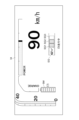
- the display device 22 displays, for example, an SOC meter SM that displays the charging rate of the driving battery, and when the EV priority mode is selected, a plurality of segments SG1 to Although SG3 is displayed side by side with the SOC meter SM, the display of the SOC meter SM is optional and not essential.
- the display control device 20 has a charge lighting number determination section 36 , a negative pressure lighting number determination section 38 , an output lighting number determination section 40 , and a lighting number instruction section 42 .
- a plurality of segments SG1 to SG3 are assigned charging rates ranging from the maximum charging rate of the driving battery to the charging threshold at which the engine is started, and the charge lighting number determination unit 36 determines the number of lighting corresponding to the charging rate of the driving battery. (Hereinafter, “the number of charging lights" is determined.
- a required output ranging from an output that can be output with the engine stopped to an output threshold value at which the engine starts is assigned.
- a lighting number hereinafter referred to as "output lighting number" corresponding to the difference between the output that can be output and the required output is determined.
- the number-of-lighting instruction unit 42 determines the number of charging lights determined by the number-of-charge-lighting determination unit 36 and the number of negative-pressure lighting determined by the negative-voltage-lighting-number determination unit 38.
- the display device 22 is instructed to light the segments SG1 to SG3 having the smallest number among the number of voltage lighting or the number of output lighting determined by the output lighting number determination unit 40 .
- the charging lighting number determining section 36 determines the charging lighting number corresponding to the charging rate of the driving battery (step S13).
- the negative pressure lighting number determination unit 38 determines the negative pressure lighting number corresponding to the negative pressure of the brake booster 14 based on the negative pressure of the brake booster 14 detected by the negative pressure detection device 16 (step S14). ).
- the output lighting number determining unit 40 calculates the difference between the output that can be output with the engine stopped and the user's required output. The output lighting number corresponding to the difference is determined (step S15).
- the number-of-lighting instruction unit 42 determines the number of charging lighting determined by the number-of-charge lighting determining unit 36, the number of negative-pressure lighting determined by the number-of-negative-pressure lighting determining unit 38, or the output determined by the output lighting determining unit.
- the display device 22 is instructed to light the segments SG1 to SG3 with the smallest number among the lighting numbers (step S16). As a result, the display device 22 lights up the number of segments SG1 to SG3 indicated by the lighting number indicating section 42 (display control device 20). Thereafter, steps S13 to S17 are repeated until the EV priority mode is canceled by the EV priority mode selection device 10 (the EV priority mode is turned OFF).
- step S17 when the EV priority mode is canceled (EV priority mode is turned OFF) by the EV priority mode selection device 10 (step S17: Yes), a plurality of segments displayed on the display device 22 according to the instruction from the display control device 20 SG1 to SG4 are hidden until the EV priority mode is selected again (step S18).
- the driving battery may be charged by the regenerative braking operation. While the vehicle is running, the charge lighting number determination unit 36 may be restricted so as not to increase the charging lighting number. When the EV priority mode is selected and EV driving is disabled (engine driving), electricity charged in the driving battery may be consumed by operating the accelerator pedal. While the vehicle is running, the charge lighting number determination unit 36 may be restricted so as not to decrease the charging lighting number. Similarly, the negative pressure of the brake booster 14 may be consumed by operating the brake pedal, but during engine running, the negative pressure lighting number determination unit 38 may limit the negative pressure lighting number so as not to decrease. .
- the display device 22 when the EV priority mode is selected and the EV traveling is possible, the display device 22 displays the "EV traveling In addition to displaying the characters "medium", the characters "waiting" may be displayed according to an instruction from the display control device 20 when the EV running is disabled. Further, in the support system 1B according to the second embodiment, when the EV priority mode mode is selected and EV travel is possible, the display device 22 is arranged in line according to an instruction from the display control device 20.
- the lighting color of the plurality of segments SG1 to SG3 is set to one lighting color (for example, green), when the EV traveling is impossible, the plurality of segments SG1 to SG3 arranged in a row according to an instruction from the display control device 20
- the lighting color of SG3 may be another lighting color (for example, orange).
- Other configurations are the same as those of the support system 1A according to the first embodiment.
- step S23 it is determined whether EV driving is possible (step S23). Then, EV driving is possible (step S23: Yes), that is, when the charging rate of the driving battery exceeds the charging threshold, the negative pressure of the brake booster 14 exceeds the negative pressure threshold, and the output requested by the user is below the output threshold. If so, the EV display EG is turned on (step S24). On the other hand, EV driving is impossible (step S23: No), that is, when the charging rate of the drive battery is equal to or less than the charge threshold, the negative pressure of the brake booster 14 is equal to or less than the negative pressure threshold, or the output requested by the user is equal to or greater than the output threshold. , the EV display EG is extinguished (step S25). Thereafter, steps S23 to S26 are repeated until the EV priority mode is canceled by the EV priority mode selection device 10 (the EV priority mode is turned OFF).
- step S26 when the EV priority mode is canceled (EV priority mode is turned OFF) by the EV priority mode selection device 10 (step S26: Yes), the EV display EG displayed on the display device 22 according to the instruction from the display control device 20 is hidden until the EV priority mode is selected again (step S27).
- Other operations are the same as those of the support system 1A according to the first embodiment.
- the support system 1C according to the third embodiment includes a charge mode selection device 44 that enables selection of a charge mode for charging the drive battery with electricity generated by the engine.
- the charge mode selection device 44 is composed of, for example, an EV mode selector switch 26 provided adjacent to the selector lever 24 .
- the number-of-lighting instruction unit 42 when the charge mode selection device 44 selects the charge mode, determines the number of segments SG1 to The display device 22 is instructed to turn on SG3.
- Other configurations are the same as those of the support system 1A or 1B according to the first or second embodiment.
- the charging lighting number determining section 36 determines the charging lighting number corresponding to the charging rate of the driving battery (step S33).
- the number-of-lighting instruction unit 42 instructs the display device 22 to turn on the number of charging lighting determined by the number-of-charging lighting determining unit 36 (step S34).
- the display device 22 lights up the number of segments SG1 to SG3 indicated by the lighting number indicating section 42 (display control device 20).
- steps S33 to S35 are repeated until the charge mode selection device 44 cancels the charge mode (the charge mode is turned OFF) (step S35: Yes).
- the charge mode selection device 44 when the charge mode is canceled (the charge mode is turned off) by the charge mode selection device 44, the charge mode is selected again for the plurality of segments SG1 to SG3 displayed on the display device 22 according to the instruction from the display control device 20. hidden until Other operations are the same as those of the support system 1A or 1B according to the first or second embodiment.
- the plurality of segments SG1 to SG4 are composed of four segments SG1 to SG4 arranged in a row on the left and right, and the driving battery It includes segment SG4 for displaying full charge, which lights up when the charging rate is equal to or higher than a predetermined full charging rate.
- the full charge rate is a charge rate at which the vehicle is fully charged, is equal to or less than the maximum charge rate, and is assigned to the three segments SG1 to SG3 from the left of the four segments SG1 to SG4 arranged horizontally.
- a charging rate equal to or higher than the minimum charging rate assigned to at least the third segment SG3 is set.
- the segment SG4 for displaying the full charge is the first segment SG4 from the right when the four segments SG1 to SG4 arranged in a line from left to right are formed.
- Other configurations are the same as those of any one of the support systems 1A, 1B, and 1C according to the first to third embodiments.
- the charge mode is selected by the charge mode selection device 44, and the charging rate of the drive battery detected by the charging rate detection device 12 becomes more than full charge due to the operation of the engine.
- the full charge display segment SG4 lights up.
- the user can visually recognize whether the charging rate of the driving battery is equal to or higher than the full charging rate.
- 1A, 1B, 1C, 1D support system 10 EV priority mode selection device 12 charging rate detection device 14 brake booster 16 negative pressure detection device 18 required output detection device 20 display control device 22 display device 24 selector lever 26 EV mode selector switch 28 pressure Sensor 30 Accelerator pedal 32 Accelerator pedal position sensor 34 Multi-information display 36 Charge lighting number determination unit 38 Negative pressure lighting number determination unit 40 Output lighting number determination unit 42 Lighting number instruction unit 44 Charge mode selection device SG1 to SG3, SG4 Segment SM SOC Meter EG EV display
Abstract
A display control device in this support system comprises: a charge light-up number determination unit that, where a state of charge from the maximum state of charge of a driving battery to a charging threshold is divided into a plurality of segments, determines a charge light-up number that corresponds to the state of charge; an output light-up number determination unit that, where a requested output from an output that can be output to an output threshold is divided into a plurality of segments, determines an output light-up number that corresponds to a difference; and a light-up number instruction unit that, if an EV prioritization mode is selected, instructs a display device to light up the segments of the smaller number between the charge light-up number and the output light-up number.
Description
本開示は、ハイブリッド自動車のEV走行の継続を支援する支援システムに関する。
This disclosure relates to a support system that supports continuation of EV driving of a hybrid vehicle.
特許文献1には、内燃機関と、蓄電装置から電力の供給を受けて車両駆動力を発生させる駆動用モータとを動力源とする車両の車両用制御装置が開示されている。かかる車両用制御装置は、蓄電装置の残容量を検出するための検出部と、内燃機関を停止させた状態で駆動用モータを用いるモータ走行を優先するための第1モードと、残容量が第1閾値よりも低下した場合に、選択中の走行モードに関係なく内燃機関と駆動用モータとを用いたハイブリッド走行を強制的に優先するための第2モードとのうちのいずれか一つの走行モードを選択するための制御部とを含んでいる。
Patent Literature 1 discloses a vehicle control device for a vehicle that uses an internal combustion engine and a driving motor that receives electric power from a power storage device and generates vehicle driving force as power sources. Such a vehicle control device includes a detection unit for detecting the remaining capacity of the power storage device, a first mode for giving priority to motor running using the drive motor while the internal combustion engine is stopped, and a first mode for determining the remaining capacity of the power storage device. any one of a second mode for forcibly prioritizing hybrid driving using an internal combustion engine and a drive motor regardless of the selected driving mode when the driving mode is lower than the 1 threshold. and a control for selecting the
また、特許文献1に開示された車両には、残容量を表示するための表示装置が設けられている。表示装置は、残容量の下限値から上限値までに対応した、点灯可能な複数のセグメントの各々の点灯の有無によって、残容量が複数の段階のうちのいずれの段階であるかを表示する。
In addition, the vehicle disclosed in Patent Document 1 is provided with a display device for displaying the remaining capacity. The display device displays which stage of the remaining capacity is in a plurality of stages depending on whether or not each of the plurality of segments that can be lit corresponding to the lower limit value to the upper limit value of the remaining capacity is lit.
ところで、ユーザの要求出力が予め定められた閾値(出力閾値)以上となった場合には蓄電装置の残容量に余裕があっても内燃機関が始動し、モータ走行(EV走行)を継続することができない。
By the way, when the output requested by the user exceeds a predetermined threshold value (output threshold value), the internal combustion engine is started even if there is a margin in the remaining capacity of the power storage device, and the motor running (EV running) is continued. can't
したがって、残容量の下限値から上限値までに対応した、点灯可能な複数のセグメントの各々の点灯の有無によって、残容量が複数の段階のうちのいずれの段階であるかを表示するだけではEV走行の継続を支援することができない(EV走行距離を延ばすことができない)。
Therefore, it is not enough to simply display which stage of the remaining capacity is in a plurality of stages depending on whether or not each of the plurality of segments that can be lit corresponding to the lower limit value to the upper limit value of the remaining capacity is lit. Continuation of driving cannot be supported (EV driving distance cannot be extended).
上述の事情に鑑みて、本発明の少なくとも一実施形態は、EV走行の継続を支援することができる支援システムを提供することを目的とする。
In view of the circumstances described above, at least one embodiment of the present invention aims to provide a support system capable of supporting continuation of EV driving.
(1)本発明の少なくとも一実施形態に係る支援システムは、エンジンを運転した状態で走行するエンジン走行よりも前記エンジンを停止した状態で走行するEV走行を優先するEV優先モードが選択可能であって、前記EV優先モードが選択されている場合であっても、駆動用バッテリの充電率が予め定められた充電閾値以下、又はユーザの要求出力が予め定められた出力閾値以上となった場合に前記エンジンを始動するハイブリッド自動車のEV走行の継続を支援システムであって、前記EV優先モードを選択するためのEV優先モード選択装置と、前記充電率を検出する充電率検出装置と、前記要求出力を検出する要求出力検出装置と、表示制御装置と、前記EV優先モードが選択された場合に、前記表示制御装置からの指示により、一列に並んだ複数のセグメントを表示する表示装置と、を備え、前記表示制御装置は、前記充電率が前記複数のセグメントの点灯数に対応するように、前記駆動用バッテリの最大充電率から前記充電閾値に至る前記充電率が前記複数のセグメントに割り当てられ、前記充電率に対応する充電点灯数を決定する充電点灯数決定部と前記エンジンを停止した状態で出力可能な出力と前記要求出力との差分が前記複数のセグメントの点灯数に対応するように、前記出力可能な出力から前記出力閾値に至る前記要求出力が前記複数のセグメントに割り当てられ、前記差分に対応する出力点灯数を決定する出力点灯数決定部と、前記EV優先モードが選択された場合に、前記充電点灯数、又は前記出力点灯数のうち、最も数が少ない数のセグメントを点灯するように前記表示装置に指示する点灯数指示部とを有する。
(1) The support system according to at least one embodiment of the present invention is capable of selecting an EV priority mode in which EV driving with the engine stopped is prioritized over engine driving with the engine running. Therefore, even when the EV priority mode is selected, if the charging rate of the drive battery is equal to or less than a predetermined charging threshold, or if the output requested by the user is equal to or greater than a predetermined output threshold, A system for supporting continuation of EV driving of a hybrid vehicle whose engine is started, comprising an EV priority mode selection device for selecting the EV priority mode, a charging rate detection device for detecting the charging rate, and the requested output. a display control device; and a display device for displaying a plurality of segments arranged in a line according to an instruction from the display control device when the EV priority mode is selected. the display control device assigns the charging rate from the maximum charging rate of the drive battery to the charging threshold to the plurality of segments so that the charging rate corresponds to the number of lights of the plurality of segments; A charge lighting number determination unit that determines the charging lighting number corresponding to the charging rate, and the difference between the output that can be output with the engine stopped and the required output corresponds to the lighting number of the plurality of segments, When the required output from the output that can be output to the output threshold is assigned to the plurality of segments, and an output lighting number determination unit that determines the output lighting number corresponding to the difference, and the EV priority mode is selected. and a number-of-lighting instructing unit that instructs the display device to light the segment with the smallest number of the number of lights for charging or the number of lights for output.
上記(1)の構成によれば、EV優先モードが選択された場合に、充電点灯数、又は出力点灯数のうち、最も数が少ない数のセグメントを点灯するので、ユーザはセグメント点灯数(消灯数)を見ながら急激なアクセルペダル操作を避けて、ブレーキペダル操作よりも回生ブレーキ操作を優先することで、EV走行の継続を図ることができる(EV走行の継続支援)。
According to the configuration (1) above, when the EV priority mode is selected, the segment with the smallest number among the number of charging lights and the number of output lights is lit. EV driving can be continued by avoiding abrupt accelerator pedal operation and prioritizing regenerative brake operation over brake pedal operation while watching the number) (EV driving continuation support).
(2)幾つかの実施形態では、上記(1)の構成において、前記エンジンにより発電された電気を駆動用バッテリに充電するチャージモードの選択を可能にするチャージモード選択装置を備え、前記点灯数指示部は、前記チャージモードが選択された場合に、前記充電点灯数のセグメントを点灯するように前記表示装置に指示する。
(2) In some embodiments, in the configuration of (1) above, a charge mode selection device that enables selection of a charge mode for charging a drive battery with electricity generated by the engine is provided, and the number of lighting The instruction unit instructs the display device to light up the segments corresponding to the charging lighting number when the charging mode is selected.
上記(2)の構成によれば、チャージモードが選択された場合に、充電点灯数のセグメントを点灯することで、駆動用バッテリの充電率をユーザに視覚的に認識させることができる。
According to the above configuration (2), when the charge mode is selected, by lighting the segments for the number of charging lights, the user can be made to visually recognize the charging rate of the driving battery.
(3)幾つかの実施形態では、上記(1)又は(2)の構成において、前記EV優先モードが選択された場合であって、前記EV走行が可能な場合に、前記表示装置は、前記表示制御装置からの指示により、EV表示を点灯する一方、前記EV走行が不能な場合に、前記表示制御装置からの指示により、前記EV表示を消灯する。
(3) In some embodiments, in the configuration (1) or (2) above, when the EV priority mode is selected and the EV travel is possible, the display device displays the The EV display is turned on according to an instruction from the display control device, and the EV display is turned off according to an instruction from the display control device when the EV running is disabled.
上記(3)の構成によれば、EV表示の点灯によりEV走行が可能であることをユーザに認識させ、EV表示の消灯によりEV走行が不能であること(エンジン走行すること)をユーザに認識させることができる。また、EV表示の消灯により、エンジン走行からEV走行への復帰のためにエンジンにより発電された電気が駆動用バッテリに充電されていること、及び、回生ブレーキによって駆動用バッテリが充電されていることをユーザに認識させることができる。これにより、エンジン走行からEV走行に復帰するために、ユーザは急激なアクセルペダル操作を避けて、ブレーキペダル操作よりも回生ブレーキ操作を優先するように促すことができる。また、エンジン走行からEV走行に復帰するとEV表示が消灯から点灯に移行するので、ユーザはエンジン走行からEV走行に復帰するタイミングを視覚的に認識することができる。
According to the above configuration (3), the lighting of the EV display allows the user to recognize that the EV running is possible, and the turning off of the EV display allows the user to recognize that the EV running is impossible (engine running). can be made In addition, when the EV display is turned off, the driving battery is charged with electricity generated by the engine in order to return from engine driving to EV driving, and the driving battery is being charged by regenerative braking. can be recognized by the user. As a result, in order to return from engine running to EV running, the user can be urged to avoid abrupt accelerator pedal operation and give priority to regenerative brake operation over brake pedal operation. Further, when the engine running is returned to the EV running, the EV display is switched from off to on, so that the user can visually recognize the timing of returning from the engine running to the EV running.
(4)幾つかの実施形態では、上記(1)から(3)のいずれか一つの構成において、前記複数のセグメントは、前記駆動用バッテリの充電率が予め定めた満充電率以上の場合に点灯する満充電表示用のセグメントを含む。
(4) In some embodiments, in the configuration of any one of (1) to (3) above, the plurality of segments are connected when the charging rate of the driving battery is equal to or higher than a predetermined full charging rate. Includes segment for full charge indicator that lights up.
上記(4)の構成によれば、駆動用バッテリの充電率が満充電率以上であるか否かをユーザに視覚的に認識させることができる。
According to the above configuration (4), it is possible for the user to visually recognize whether or not the charging rate of the drive battery is equal to or higher than the full charging rate.
(5)幾つかの実施形態では、上記(1)から(5)のいずれか一つの構成において、前記支援システムは、ブレーキブースタの負圧が予め定められた負圧閾値以下となった場合に、前記エンジンを始動する支援システムであって、前記負圧を検出する負圧検出装置と、前記負圧が前記複数のセグメントの点灯数に対応するように、前記ブレーキブースタに蓄えられる最大負圧から前記負圧閾値に至る前記負圧が前記複数のセグメントに割り当てられ、前記負圧に対応する負圧点灯数を決定する負圧点灯数決定部と、を備え、前記点灯数指示部は、前記EV優先モードが選択された場合に、前記充電点灯数、前記負圧点灯数、又は前記出力点灯数のうち、最も数が少ない数のセグメントを点灯するように前記表示装置に指示する。
(5) In some embodiments, in the configuration of any one of (1) to (5) above, the support system, when the negative pressure of the brake booster becomes equal to or lower than a predetermined negative pressure threshold, and a maximum negative pressure stored in the brake booster so that the negative pressure corresponds to the lighting number of the plurality of segments. a negative pressure lighting number determining unit that determines the number of negative pressure lighting corresponding to the negative pressure assigned to the plurality of segments, the lighting number instructing unit comprising: When the EV priority mode is selected, the display device is instructed to light the segment having the smallest number among the number of charging lighting, the number of negative pressure lighting, or the number of output lighting.
上記(5)の構成によれば、EV優先モードが選択された場合に、充電点灯数、負圧点灯数又は出力点灯数のうち、最も数が少ない数のセグメントを点灯するので、ユーザはセグメント点灯数(消灯数)を見ながら急激なアクセルペダル操作を避けて、ブレーキペダル操作よりも回生ブレーキ操作を優先することで、EV走行の継続を図ることができる。
According to the above configuration (5), when the EV priority mode is selected, the segment with the smallest number among the number of charging lights, the number of negative pressure lights, or the number of output lights is lit. EV driving can be continued by avoiding abrupt accelerator pedal operation while watching the number of lights on (number of lights off) and prioritizing regenerative brake operation over brake pedal operation.
(6)幾つかの実施形態では、上記(1)から(5)のいずれか一つの構成において、前記表示装置は、前記駆動用バッテリの充電率を表示するSOCメータを表示する。
(6) In some embodiments, in the configuration of any one of (1) to (5) above, the display device displays an SOC meter that displays the charging rate of the drive battery.
上記(6)の構成によれば、駆動用バッテリの充電率と、エンジンの始動までにどれくらいの余裕があるかをユーザに視覚的に認識させることができる。
According to the above configuration (6), the user can visually recognize the charging rate of the driving battery and how much time is left until the engine starts.
本発明の少なくとも一実施形態によれば、EV走行の継続を図ることができる(EV走行の継続支援)。
According to at least one embodiment of the present invention, EV driving can be continued (EV driving continuation support).
以下、添付図面を参照して本発明の幾つかの実施形態について説明する。ただし、実施形態として記載されている又は図面に示されている構成部品の寸法、材質、形状、その相対的配置等は、本発明の範囲をこれに限定する趣旨ではなく、単なる説明例にすぎない。
Several embodiments of the present invention will be described below with reference to the accompanying drawings. However, the dimensions, materials, shapes, relative arrangements, etc. of the components described as embodiments or shown in the drawings are not intended to limit the scope of the present invention, and are merely illustrative examples. do not have.
[実施形態1]
[ハイブリッド自動車の概要]
実施形態1に係る支援システムが搭載される自動車は、エンジン及びモータを動力源とするハイブリッド自動車であって、エンジンを運転状態で走行するエンジン走行とエンジンを停止した状態で走行するEV走行とが可能である。ハイブリッド自動車は、例えば、外部充電によって外部電源から充電可能、もしくは外部機器への外部給電可能なプラグインハイブリッド自動車(PHEV,PHV)であるが、プラグインハイブリッド自動車に限定されるものではない。 [Embodiment 1]
[Overview of hybrid vehicle]
The vehicle on which the support system according to the first embodiment is installed is a hybrid vehicle that uses an engine and a motor as power sources, and is divided into engine running in which the engine is running and EV running in which the engine is stopped. It is possible. A hybrid vehicle is, for example, a plug-in hybrid vehicle (PHEV, PHV) that can be charged from an external power source by external charging or that can externally supply power to an external device, but is not limited to a plug-in hybrid vehicle.
また、実施形態1に係るハイブリッド自動車は、エンジン走行よりもEV走行を優先するEV優先モードを選択するEV優先モードが選択可能であって、EV優先モードが選択されている場合であっても、駆動用バッテリの充電率(SOC(State Of Charge))が予め定められた充電閾値以下、ブレーキブースタの負圧が予め定められた負圧閾値以下、又は、ユーザの要求出力が予め定められた出力閾値以上となった場合にエンジンを始動するように構成されている。
Further, the hybrid vehicle according to the first embodiment is capable of selecting an EV priority mode in which EV driving is prioritized over engine driving, and even if the EV priority mode is selected, The charging rate (SOC (State Of Charge)) of the driving battery is equal to or less than a predetermined charge threshold, the negative pressure of the brake booster is equal to or less than a predetermined negative pressure threshold, or the output requested by the user is a predetermined output It is configured to start the engine when the threshold value is exceeded.
また、実施形態1に係るハイブリッド自動車は、エンジンが始動した場合に、駆動用バッテリの充電率が予め定めたエンジン停止充電閾値以上、ブレーキブースタの負圧が予め定めたエンジン停止負圧閾値以上、及びユーザの要求出力が出力閾値以下となった場合にエンジンを停止するように構成されている。エンジン停止充電閾値は、駆動用バッテリの最大充電率以下であって充電閾値以上の範囲で任意に設定され、エンジン停止負圧閾値は、ブレーキブースタに蓄えられる最大負圧以下であって負圧閾値以上の範囲で任意に設定される。
Further, in the hybrid vehicle according to the first embodiment, when the engine is started, the charging rate of the driving battery is equal to or higher than a predetermined engine stop charge threshold, the negative pressure of the brake booster is equal to or higher than a predetermined engine stop negative pressure threshold, and the engine is stopped when the output requested by the user falls below the output threshold. The engine stop charging threshold is arbitrarily set within a range between the maximum charging rate of the drive battery and the charging threshold, and the engine stop negative pressure threshold is the maximum negative pressure stored in the brake booster and below the negative pressure threshold. It is set arbitrarily within the above range.
[支援システムの構成]
実施形態1に係る支援システム1Aは、EV走行の継続を支援するシステムであって、図1に示すように、EV優先モードを選択するためのEV優先モード選択装置10、駆動用バッテリの充電率を検出する充電率検出装置12、ブレーキブースタ14の負圧を検出する負圧検出装置16、ユーザの要求出力を検出する要求出力検出装置18、表示制御装置20、及びEV優先モードが選択された場合に、表示制御装置20からの指示により、一列に並んだ複数のセグメントSG1~SG3を表示する表示装置22を備えている。 [Configuration of support system]
Asupport system 1A according to the first embodiment is a system for supporting continuation of EV travel, and as shown in FIG. , the negative pressure detection device 16 that detects the negative pressure of the brake booster 14, the requested output detection device 18 that detects the user's requested output, the display control device 20, and the EV priority mode are selected. In this case, a display device 22 is provided for displaying a plurality of segments SG1 to SG3 arranged in a line according to an instruction from the display control device 20. FIG.
実施形態1に係る支援システム1Aは、EV走行の継続を支援するシステムであって、図1に示すように、EV優先モードを選択するためのEV優先モード選択装置10、駆動用バッテリの充電率を検出する充電率検出装置12、ブレーキブースタ14の負圧を検出する負圧検出装置16、ユーザの要求出力を検出する要求出力検出装置18、表示制御装置20、及びEV優先モードが選択された場合に、表示制御装置20からの指示により、一列に並んだ複数のセグメントSG1~SG3を表示する表示装置22を備えている。 [Configuration of support system]
A
EV優先モード選択装置10は、例えば、セレクタレバー24と隣り合う位置に設けられたEVモードセレクタスイッチ26により構成され、EVプライオリティモードを選択することによって、EV優先モードが選択される。充電率検出装置12は、例えば、駆動用バッテリに設けられたバッテリマネージメントシステム(図示せず)によって構成される。負圧検出装置16は、例えば、ブレーキブースタ14に設けられた圧力センサ28によって構成される。要求出力検出装置18は、例えば、アクセルペダル30の踏み込み量を検出するアクセルペダルポジションセンサ32によって構成される。表示装置22は、例えば、メータ内に設けられたマルチインフォメーションディスプレイ34によって構成される。表示制御装置20は、例えば、演算装置、命令や情報を格納するレジスタ、及び周辺回路等から構成されるプロセッサ(図示せず)、ROM(Read Only Memory)、RAM(Random Acsess Memory)等のメモリ(図示せず)、及び入出力インタフェース(図示せず)によって構成される。図2に示すように、表示装置22には、例えば、駆動用バッテリの充電率を表示するSOCメータSMが表示され、EV優先モードが選択された場合に、一列に並んだ複数のセグメントSG1~SG3がSOCメータSMと横並びに表示されるが、SOCメータSMの表示は必須ではなく任意である。また、一列に並んだ複数のセグメントSG1~SG3は、例えば、左右に並んだ3つのセグメントSG1~SG3で構成されるが、複数のセグメントSG1~SG3の数は3つに限られるものではない。
The EV priority mode selection device 10 is composed of, for example, an EV mode selector switch 26 provided at a position adjacent to the selector lever 24, and the EV priority mode is selected by selecting the EV priority mode. The charging rate detection device 12 is configured by, for example, a battery management system (not shown) provided in the drive battery. The negative pressure detection device 16 is composed of, for example, a pressure sensor 28 provided in the brake booster 14 . The required output detection device 18 is composed of, for example, an accelerator pedal position sensor 32 that detects the depression amount of the accelerator pedal 30 . The display device 22 is configured by, for example, a multi-information display 34 provided within the meter. The display control device 20 includes, for example, a processor (not shown) composed of an arithmetic unit, registers for storing instructions and information, peripheral circuits, etc., memories such as ROM (Read Only Memory) and RAM (Random Access Memory). (not shown) and an input/output interface (not shown). As shown in FIG. 2, the display device 22 displays, for example, an SOC meter SM that displays the charging rate of the driving battery, and when the EV priority mode is selected, a plurality of segments SG1 to Although SG3 is displayed side by side with the SOC meter SM, the display of the SOC meter SM is optional and not essential. Further, the plurality of segments SG1 to SG3 arranged in a row is composed of, for example, three segments SG1 to SG3 arranged in a horizontal line, but the number of the plurality of segments SG1 to SG3 is not limited to three.
[表示制御装置20の詳細構成]
図1に示すように、表示制御装置20は、充電点灯数決定部36、負圧点灯数決定部38、出力点灯数決定部40、及び点灯数指示部42を有している。 [Detailed Configuration of Display Control Device 20]
As shown in FIG. 1 , thedisplay control device 20 has a charge lighting number determination section 36 , a negative pressure lighting number determination section 38 , an output lighting number determination section 40 , and a lighting number instruction section 42 .
図1に示すように、表示制御装置20は、充電点灯数決定部36、負圧点灯数決定部38、出力点灯数決定部40、及び点灯数指示部42を有している。 [Detailed Configuration of Display Control Device 20]
As shown in FIG. 1 , the
複数のセグメントSG1~SG3には、駆動用バッテリの最大充電率からエンジンが始動する充電閾値に至る充電率が割り当てられ、充電点灯数決定部36は、駆動用バッテリの充電率に対応する点灯数(以下「充電点灯数という」を決定する。
A plurality of segments SG1 to SG3 are assigned charging rates ranging from the maximum charging rate of the driving battery to the charging threshold at which the engine is started, and the charge lighting number determination unit 36 determines the number of lighting corresponding to the charging rate of the driving battery. (Hereinafter, "the number of charging lights" is determined.
また、複数のセグメントSG1~SG3には、ブレーキブースタ14に蓄えられる最大負圧からエンジンが始動する負圧閾値に至る負圧が割り当てられ、負圧点灯数決定部38は、ブレーキブースタ14の負圧に対応する点灯数(以下「負圧点灯数」という)を決定する。
Negative pressure ranging from the maximum negative pressure stored in the brake booster 14 to the negative pressure threshold at which the engine is started is assigned to the plurality of segments SG1 to SG3. The number of lights corresponding to the pressure (hereinafter referred to as "the number of negative pressure lights") is determined.
また、複数のセグメントSG1~SG3には、エンジンを停止した状態で出力可能な出力からエンジンが始動する出力閾値に至る要求出力が割り当てられ、出力点灯数決定部40は、エンジンを停止した状態で出力可能な出力と要求出力との差分に対応する点灯数(以下「出力点灯数」という)を決定する。
In addition, to the plurality of segments SG1 to SG3, a required output ranging from an output that can be output with the engine stopped to an output threshold value at which the engine starts is assigned. A lighting number (hereinafter referred to as "output lighting number") corresponding to the difference between the output that can be output and the required output is determined.
点灯数指示部42は、EV優先モード選択装置10によってEV優先モードが選択された場合に、充電点灯数決定部36で決定された充電点灯数、負圧点灯数決定部38で決定された負圧点灯数、又は出力点灯数決定部40で決定された出力点灯数のうち、最も数が少ない数のセグメントSG1~SG3を点灯するように表示装置22に指示する。
When the EV priority mode is selected by the EV priority mode selection device 10, the number-of-lighting instruction unit 42 determines the number of charging lights determined by the number-of-charge-lighting determination unit 36 and the number of negative-pressure lighting determined by the negative-voltage-lighting-number determination unit 38. The display device 22 is instructed to light the segments SG1 to SG3 having the smallest number among the number of voltage lighting or the number of output lighting determined by the output lighting number determination unit 40 .
[支援システム1Aの動作]
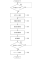
図3に示すように、実施形態1に係る支援システム1Aでは、EV優先モード選択装置10によってEV優先モードが選択(EV優先モードON)される(ステップS11:Yes)と、表示制御装置20からの指示により、表示装置22に一列に並んだ複数のセグメントSG1~SG3を表示する(ステップS12)。 [Operation ofsupport system 1A]
As shown in FIG. 3, in thesupport system 1A according to the first embodiment, when the EV priority mode is selected (EV priority mode ON) by the EV priority mode selection device 10 (step S11: Yes), the display control device 20 , a plurality of segments SG1 to SG3 arranged in a row are displayed on the display device 22 (step S12).
図3に示すように、実施形態1に係る支援システム1Aでは、EV優先モード選択装置10によってEV優先モードが選択(EV優先モードON)される(ステップS11:Yes)と、表示制御装置20からの指示により、表示装置22に一列に並んだ複数のセグメントSG1~SG3を表示する(ステップS12)。 [Operation of
As shown in FIG. 3, in the
次に、充電点灯数決定部36が、充電率検出部で検出された駆動用バッテリの充電率に基づいて、駆動用バッテリの充電率に対応する充電点灯数を決定するステップS13)。次に、負圧点灯数決定部38が、負圧検出装置16で検出されたブレーキブースタ14の負圧に基づいて、ブレーキブースタ14の負圧に対応する負圧点灯数を決定する(ステップS14)。次に、出力点灯数決定部40が、要求出力検出装置18で検出されたユーザの要求出力に基づいて、エンジンを停止した状態で出力可能な出力とユーザの要求出力の差分を算出し、この差分に対応する出力点灯数を決定する(ステップS15)。
Next, based on the charging rate of the driving battery detected by the charging rate detecting section, the charging lighting number determining section 36 determines the charging lighting number corresponding to the charging rate of the driving battery (step S13). Next, the negative pressure lighting number determination unit 38 determines the negative pressure lighting number corresponding to the negative pressure of the brake booster 14 based on the negative pressure of the brake booster 14 detected by the negative pressure detection device 16 (step S14). ). Next, based on the user's required output detected by the required output detection device 18, the output lighting number determining unit 40 calculates the difference between the output that can be output with the engine stopped and the user's required output. The output lighting number corresponding to the difference is determined (step S15).
次に、点灯数指示部42が、充電点灯数決定部36で決定された充電点灯数、負圧点灯数決定部38で決定された負圧点灯数、又は出力点灯決定部で決定された出力点灯数のうち、最も数が少ない数のセグメントSG1~SG3を点灯するように表示装置22に指示する(ステップS16)。これにより、表示装置22は、点灯数指示部42(表示制御装置20)に指示された数のセグメントSG1~SG3を点灯する。以下、EV優先モード選択装置10によってEV優先モードが解消(EV優先モードがOFF)されるまで、ステップS13からステップS17を繰り返す。
Next, the number-of-lighting instruction unit 42 determines the number of charging lighting determined by the number-of-charge lighting determining unit 36, the number of negative-pressure lighting determined by the number-of-negative-pressure lighting determining unit 38, or the output determined by the output lighting determining unit. The display device 22 is instructed to light the segments SG1 to SG3 with the smallest number among the lighting numbers (step S16). As a result, the display device 22 lights up the number of segments SG1 to SG3 indicated by the lighting number indicating section 42 (display control device 20). Thereafter, steps S13 to S17 are repeated until the EV priority mode is canceled by the EV priority mode selection device 10 (the EV priority mode is turned OFF).
一方、EV優先モード選択装置10によってEV優先モードが解消(EV優先モードがOFF)される(ステップS17:Yes)と、表示制御装置20からの指示により、表示装置22に表示された複数のセグメントSG1~SG4は再びEV優先モードが選択されるまで非表示となる(ステップS18)。
On the other hand, when the EV priority mode is canceled (EV priority mode is turned OFF) by the EV priority mode selection device 10 (step S17: Yes), a plurality of segments displayed on the display device 22 according to the instruction from the display control device 20 SG1 to SG4 are hidden until the EV priority mode is selected again (step S18).
尚、実施形態1に係る支援システム1Aでは、EV優先モードが選択された場合であって、EV走行が可能な場合には、回生ブレーキ操作によって駆動用バッテリが充電されることがあるが、EV走行中は、充電点灯数決定部36が充電点灯数を増加させないように制限してもよい。また、EV優先モードが選択された場合であって、EV走行が不能な場合(エンジン走行する)には、アクセルペダル操作によって駆動用バッテリに充電された電気が消費されることがあるが、エンジン走行中は、充電点灯数決定部36が充電点灯数を減少させないように制限してもよい。同様に、ブレーキペダル操作によってブレーキブースタ14の負圧が消費されたりすることがあるが、エンジン走行中は、負圧点灯数決定部38が負圧点灯数を減少させないように制限してもよい。
In the support system 1A according to the first embodiment, when the EV priority mode is selected and EV travel is possible, the driving battery may be charged by the regenerative braking operation. While the vehicle is running, the charge lighting number determination unit 36 may be restricted so as not to increase the charging lighting number. When the EV priority mode is selected and EV driving is disabled (engine driving), electricity charged in the driving battery may be consumed by operating the accelerator pedal. While the vehicle is running, the charge lighting number determination unit 36 may be restricted so as not to decrease the charging lighting number. Similarly, the negative pressure of the brake booster 14 may be consumed by operating the brake pedal, but during engine running, the negative pressure lighting number determination unit 38 may limit the negative pressure lighting number so as not to decrease. .
[支援システム1Aの効果]
実施形態1に係る支援システム1Aによれば、EV優先モードが選択された場合に、充電点灯数、負圧点灯数、又は出力点灯数のうち、最も少ない数のセグメントSG1~SG3を点灯するので、ユーザはセグメント点灯数(消灯数)を見ながら急激なアクセルペダル操作を避けて、ブレーキペダル操作よりも回生ブレーキ操作を優先することで、EV走行の継続を図ることができる(EV走行の継続支援)。 [Effect ofsupport system 1A]
According to thesupport system 1A according to the first embodiment, when the EV priority mode is selected, the smallest number of the segments SG1 to SG3 out of the number of charging lights, the number of negative pressure lights, or the number of output lights is lit. , the user can continue EV driving by avoiding sudden accelerator pedal operation while watching the number of segments lit (number of lights off) and prioritizing regenerative brake operation over brake pedal operation. support).
実施形態1に係る支援システム1Aによれば、EV優先モードが選択された場合に、充電点灯数、負圧点灯数、又は出力点灯数のうち、最も少ない数のセグメントSG1~SG3を点灯するので、ユーザはセグメント点灯数(消灯数)を見ながら急激なアクセルペダル操作を避けて、ブレーキペダル操作よりも回生ブレーキ操作を優先することで、EV走行の継続を図ることができる(EV走行の継続支援)。 [Effect of
According to the
[実施形態2]
[支援システムの構成]
実施形態2に係る支援システム1B(図1参照)では、EV優先モードが選択された場合であって、EV走行が可能な場合に、表示装置22は、表示制御装置20からの指示により、EV表示EGを点灯する一方、EV走行が不能な場合に、表示制御装置20からの指示により、EV表示EGを消灯する。図2に示すように、EV表示EGは、例えば、「EV」の文字を縁取ったものであり、EV表示EGを点灯した場合にEVの文字を塗りつぶして光るように構成される。また、実施形態2に係る支援システム1Bは、EV優先モードモードが選択された場合であって、EV走行が可能な場合に、表示装置22は、表示制御装置20からの指示により、「EV走行中」の文字を表示する一方、EV走行が不能な場合に、表示制御装置20からの指示により、「待機中」の文字を表示してもよい。また、実施形態2に係る支援システム1Bは、EV優先モードモードが選択された場合であって、EV走行が可能な場合に、表示装置22は、表示制御装置20からの指示により、一列に並んだ複数のセグメントSG1~SG3の点灯色を一の点灯色(例えば、緑色)とする一方、EV走行が不能な場合に、表示制御装置20からの指示により、一列に並んだ複数のセグメントSG1~SG3の点灯色を他の一の点灯色(例えば、橙色)としてもよい。他の構成は、実施形態1に係る支援システム1Aと同じである。 [Embodiment 2]
[Configuration of support system]
In thesupport system 1B (see FIG. 1) according to the second embodiment, when the EV priority mode is selected and EV travel is possible, the display device 22 is instructed by the display control device 20 to display the EV While the display EG is turned on, the EV display EG is turned off according to an instruction from the display control device 20 when the EV running is disabled. As shown in FIG. 2, the EV display EG is, for example, a framed character of "EV", and is configured to glow while the EV character is painted out when the EV display EG is turned on. Further, in the support system 1B according to the second embodiment, when the EV priority mode is selected and the EV traveling is possible, the display device 22 displays the "EV traveling In addition to displaying the characters "medium", the characters "waiting" may be displayed according to an instruction from the display control device 20 when the EV running is disabled. Further, in the support system 1B according to the second embodiment, when the EV priority mode mode is selected and EV travel is possible, the display device 22 is arranged in line according to an instruction from the display control device 20. While the lighting color of the plurality of segments SG1 to SG3 is set to one lighting color (for example, green), when the EV traveling is impossible, the plurality of segments SG1 to SG3 arranged in a row according to an instruction from the display control device 20 The lighting color of SG3 may be another lighting color (for example, orange). Other configurations are the same as those of the support system 1A according to the first embodiment.
[支援システムの構成]
実施形態2に係る支援システム1B(図1参照)では、EV優先モードが選択された場合であって、EV走行が可能な場合に、表示装置22は、表示制御装置20からの指示により、EV表示EGを点灯する一方、EV走行が不能な場合に、表示制御装置20からの指示により、EV表示EGを消灯する。図2に示すように、EV表示EGは、例えば、「EV」の文字を縁取ったものであり、EV表示EGを点灯した場合にEVの文字を塗りつぶして光るように構成される。また、実施形態2に係る支援システム1Bは、EV優先モードモードが選択された場合であって、EV走行が可能な場合に、表示装置22は、表示制御装置20からの指示により、「EV走行中」の文字を表示する一方、EV走行が不能な場合に、表示制御装置20からの指示により、「待機中」の文字を表示してもよい。また、実施形態2に係る支援システム1Bは、EV優先モードモードが選択された場合であって、EV走行が可能な場合に、表示装置22は、表示制御装置20からの指示により、一列に並んだ複数のセグメントSG1~SG3の点灯色を一の点灯色(例えば、緑色)とする一方、EV走行が不能な場合に、表示制御装置20からの指示により、一列に並んだ複数のセグメントSG1~SG3の点灯色を他の一の点灯色(例えば、橙色)としてもよい。他の構成は、実施形態1に係る支援システム1Aと同じである。 [Embodiment 2]
[Configuration of support system]
In the
[支援システム1Bの動作]
図4に示すように、実施形態2に係る支援システム1Bでは、EV優先モード選択装置10によってEV優先モードが選択(EV優先モードON)される(ステップS21:Yes)と、表示制御装置20からの指示により、表示装置22にEV表示EGを表示する(ステップS22)。 [Operation ofsupport system 1B]
As shown in FIG. 4, in thesupport system 1B according to the second embodiment, when the EV priority mode is selected (EV priority mode ON) by the EV priority mode selection device 10 (step S21: Yes), the display control device 20 , the EV display EG is displayed on the display device 22 (step S22).
図4に示すように、実施形態2に係る支援システム1Bでは、EV優先モード選択装置10によってEV優先モードが選択(EV優先モードON)される(ステップS21:Yes)と、表示制御装置20からの指示により、表示装置22にEV表示EGを表示する(ステップS22)。 [Operation of
As shown in FIG. 4, in the
次に、EV走行が可能であるか否かが判断される(ステップS23)。そして、EV走行が可能である(ステップS23:Yes)、すなわち、駆動用バッテリの充電率が充電閾値超、ブレーキブースタ14の負圧が負圧閾値超、及びユーザの要求出力が出力閾値未満の場合に、EV表示EGを点灯する(ステップS24)。一方、EV走行が不能である(ステップS23:No)、すなわち、駆動バッテリの充電率が充電閾値以下、ブレーキブースタ14の負圧が負圧閾値以下、又はユーザの要求出力が出力閾値以上の場合、EV表示EGを消灯する(ステップS25)。以下、EV優先モード選択装置10によってEV優先モードが解消(EV優先モードがOFF)されるまで、ステップS23からステップS26を繰り返す。
Next, it is determined whether EV driving is possible (step S23). Then, EV driving is possible (step S23: Yes), that is, when the charging rate of the driving battery exceeds the charging threshold, the negative pressure of the brake booster 14 exceeds the negative pressure threshold, and the output requested by the user is below the output threshold. If so, the EV display EG is turned on (step S24). On the other hand, EV driving is impossible (step S23: No), that is, when the charging rate of the drive battery is equal to or less than the charge threshold, the negative pressure of the brake booster 14 is equal to or less than the negative pressure threshold, or the output requested by the user is equal to or greater than the output threshold. , the EV display EG is extinguished (step S25). Thereafter, steps S23 to S26 are repeated until the EV priority mode is canceled by the EV priority mode selection device 10 (the EV priority mode is turned OFF).
一方、EV優先モード選択装置10によってEV優先モードが解消(EV優先モードがOFF)される(ステップS26:Yes)と、表示制御装置20からの指示により、表示装置22に表示されたEV表示EGは再びEV優先モードが選択されるまで非表示となる(ステップS27)。他の動作は、実施形態1に係る支援システム1Aと同じである。
On the other hand, when the EV priority mode is canceled (EV priority mode is turned OFF) by the EV priority mode selection device 10 (step S26: Yes), the EV display EG displayed on the display device 22 according to the instruction from the display control device 20 is hidden until the EV priority mode is selected again (step S27). Other operations are the same as those of the support system 1A according to the first embodiment.
[支援システム1Bの効果]
実施形態2に係る支援システム1Bによれば、EV表示EGの点灯によりEV走行が可能であることをユーザに認識させ、EV表示EGの消灯によりEV走行が不能であること(エンジン走行をすること)をユーザに認識させることができる。また、EV表示EGの消灯により、エンジン走行からEV走行への復帰のためにエンジンにより発電された電気が駆動用バッテリに充電されていること、及び、回生ブレーキによって駆動用バッテリが充電されていることをユーザに認識させることができる。これにより、エンジン走行からEV走行に復帰するために、ユーザは急激なアクセルペダル操作を避けて、ブレーキペダル操作よりも回生ブレーキ操作を優先するように促すことができる。また、エンジン走行からEV走行に復帰するとEV表示EGが消灯から点灯に移行するので、ユーザはエンジン走行からEV走行に復帰するタイミングを視覚的に認識することができる。 [Effect ofsupport system 1B]
According to thesupport system 1B according to the second embodiment, the lighting of the EV display EG makes the user aware that the EV driving is possible, and the turning off of the EV display EG indicates that the EV driving is not possible (engine driving). ) can be recognized by the user. When the EV display EG is turned off, the driving battery is charged with electricity generated by the engine for returning from the engine driving to the EV driving, and the driving battery is charged by the regenerative braking. The user can be made to recognize that. As a result, in order to return from engine running to EV running, the user can be urged to avoid abrupt accelerator pedal operation and give priority to regenerative brake operation over brake pedal operation. Further, when the engine running is returned to the EV running, the EV display EG is switched from off to on, so that the user can visually recognize the timing of returning from the engine running to the EV running.
実施形態2に係る支援システム1Bによれば、EV表示EGの点灯によりEV走行が可能であることをユーザに認識させ、EV表示EGの消灯によりEV走行が不能であること(エンジン走行をすること)をユーザに認識させることができる。また、EV表示EGの消灯により、エンジン走行からEV走行への復帰のためにエンジンにより発電された電気が駆動用バッテリに充電されていること、及び、回生ブレーキによって駆動用バッテリが充電されていることをユーザに認識させることができる。これにより、エンジン走行からEV走行に復帰するために、ユーザは急激なアクセルペダル操作を避けて、ブレーキペダル操作よりも回生ブレーキ操作を優先するように促すことができる。また、エンジン走行からEV走行に復帰するとEV表示EGが消灯から点灯に移行するので、ユーザはエンジン走行からEV走行に復帰するタイミングを視覚的に認識することができる。 [Effect of
According to the
[実施形態3]
[支援システムの構成]
図5に示すように、実施形態3に係る支援システム1Cは、エンジンにより発電された電気を駆動用バッテリに充電するチャージモードの選択を可能にするチャージモード選択装置44を備えている。チャージモード選択装置44は、例えば、セレクタレバー24と隣り合う位置に設けられたEVモードセレクタスイッチ26により構成される。また、実施形態3に係る支援システム1Cでは、点灯数指示部42は、チャージモード選択装置44でチャージモードが選択された場合に、充電点灯数決定部36が決定した充電点灯数のセグメントSG1~SG3を点灯するように表示装置22に指示する。他の構成は、実施形態1又は2に係る支援システム1A又は1Bと同じである。 [Embodiment 3]
[Configuration of support system]
As shown in FIG. 5, thesupport system 1C according to the third embodiment includes a charge mode selection device 44 that enables selection of a charge mode for charging the drive battery with electricity generated by the engine. The charge mode selection device 44 is composed of, for example, an EV mode selector switch 26 provided adjacent to the selector lever 24 . Further, in the support system 1C according to the third embodiment, the number-of-lighting instruction unit 42, when the charge mode selection device 44 selects the charge mode, determines the number of segments SG1 to The display device 22 is instructed to turn on SG3. Other configurations are the same as those of the support system 1A or 1B according to the first or second embodiment.
[支援システムの構成]
図5に示すように、実施形態3に係る支援システム1Cは、エンジンにより発電された電気を駆動用バッテリに充電するチャージモードの選択を可能にするチャージモード選択装置44を備えている。チャージモード選択装置44は、例えば、セレクタレバー24と隣り合う位置に設けられたEVモードセレクタスイッチ26により構成される。また、実施形態3に係る支援システム1Cでは、点灯数指示部42は、チャージモード選択装置44でチャージモードが選択された場合に、充電点灯数決定部36が決定した充電点灯数のセグメントSG1~SG3を点灯するように表示装置22に指示する。他の構成は、実施形態1又は2に係る支援システム1A又は1Bと同じである。 [Embodiment 3]
[Configuration of support system]
As shown in FIG. 5, the
[支援システム1Cの動作]
図6に示すように、実施形態3に係る支援システム1Cでは、チャージモード選択装置44によってチャージモードが選択(チャージモードON)される(ステップA31:Yes)と、表示制御装置20からの指示により、表示装置22に一列に並んだ複数のセグメントSG1~SG3を表示する(ステップS32:Yes)。 [Operation ofsupport system 1C]
As shown in FIG. 6, in thesupport system 1C according to the third embodiment, when the charge mode is selected (charge mode ON) by the charge mode selection device 44 (step A31: Yes), an instruction from the display control device 20 , a plurality of segments SG1 to SG3 arranged in a row are displayed on the display device 22 (step S32: Yes).
図6に示すように、実施形態3に係る支援システム1Cでは、チャージモード選択装置44によってチャージモードが選択(チャージモードON)される(ステップA31:Yes)と、表示制御装置20からの指示により、表示装置22に一列に並んだ複数のセグメントSG1~SG3を表示する(ステップS32:Yes)。 [Operation of
As shown in FIG. 6, in the
次に、充電点灯数決定部36が、充電率検出部で検出された駆動用バッテリの充電率に基づいて、駆動用バッテリの充電率に対応する充電点灯数を決定する(ステップS33)。次に、点灯数指示部42が、充電点灯数決定部36で決定された充電点灯数を点灯するように表示装置22に指示する(ステップS34)。これにより、表示装置22は、点灯数指示部42(表示制御装置20)に指示された数のセグメントSG1~SG3を点灯する。以下、チャージモード選択装置44によってチャージモードが解消(チャージモードがOFF)されるステップS35:Yes)まで、ステップS33からステップS35を繰り返す。
Next, based on the charging rate of the driving battery detected by the charging rate detecting section, the charging lighting number determining section 36 determines the charging lighting number corresponding to the charging rate of the driving battery (step S33). Next, the number-of-lighting instruction unit 42 instructs the display device 22 to turn on the number of charging lighting determined by the number-of-charging lighting determining unit 36 (step S34). As a result, the display device 22 lights up the number of segments SG1 to SG3 indicated by the lighting number indicating section 42 (display control device 20). Thereafter, steps S33 to S35 are repeated until the charge mode selection device 44 cancels the charge mode (the charge mode is turned OFF) (step S35: Yes).
一方、チャージモード選択装置44によってチャージモードが解消(チャージモードがOFF)されると、表示制御装置20からの指示により、表示装置22に表示された複数のセグメントSG1~SG3は再びチャージモードが選択されるまで非表示となる。他の動作は、実施形態1又は2に係る支援システム1A又は1Bと同じである。
On the other hand, when the charge mode is canceled (the charge mode is turned off) by the charge mode selection device 44, the charge mode is selected again for the plurality of segments SG1 to SG3 displayed on the display device 22 according to the instruction from the display control device 20. hidden until Other operations are the same as those of the support system 1A or 1B according to the first or second embodiment.
[支援システム1Cの効果]
実施形態3に係る支援システム1Cによれば、チャージモードが選択された場合に、充電点灯数のセグメントSG1~SG3を点灯するので、駆動用バッテリの充電率をユーザに視覚的に認識させることができる。 [Effect ofsupport system 1C]
According to thesupport system 1C according to the third embodiment, when the charge mode is selected, the segments SG1 to SG3 of the charging lighting number are lit, so that the user can visually recognize the charging rate of the driving battery. can.
実施形態3に係る支援システム1Cによれば、チャージモードが選択された場合に、充電点灯数のセグメントSG1~SG3を点灯するので、駆動用バッテリの充電率をユーザに視覚的に認識させることができる。 [Effect of
According to the
[実施形態4]
[支援システムの構成]
図7に示すように、実施形態4に係る支援システム1D(図5参照)では、複数のセグメントSG1~SG4は、左右に一列に並んだ4つのセグメントSG1~SG4によって構成され、駆動用バッテリの充電率が予め定めた満充電率以上の場合に点灯する満充電表示用のセグメントSG4を含む。満充電率は、満充電とされる充電率であり、最大充電率以下であって、左右に並んだ4つのセグメントSG1~SG4のうち左側から3つのセグメントSG1~SG3に充電率が割り当てられる場合に、少なくとも3つ目のセグメントSG3に割り当てられる最低充電率以上の充電率が設定される。満充電表示用のセグメントSG4は、左右に一列に並んだ4つのセグメントSG1~SG4で構成される場合に、右側から1つ目のセグメントSG4である。他の構成については、実施形態1から3に係る支援システム1A,1B,1Cのいずれかの構成と同じである。 [Embodiment 4]
[Configuration of support system]
As shown in FIG. 7, in thesupport system 1D (see FIG. 5) according to the fourth embodiment, the plurality of segments SG1 to SG4 are composed of four segments SG1 to SG4 arranged in a row on the left and right, and the driving battery It includes segment SG4 for displaying full charge, which lights up when the charging rate is equal to or higher than a predetermined full charging rate. The full charge rate is a charge rate at which the vehicle is fully charged, is equal to or less than the maximum charge rate, and is assigned to the three segments SG1 to SG3 from the left of the four segments SG1 to SG4 arranged horizontally. , a charging rate equal to or higher than the minimum charging rate assigned to at least the third segment SG3 is set. The segment SG4 for displaying the full charge is the first segment SG4 from the right when the four segments SG1 to SG4 arranged in a line from left to right are formed. Other configurations are the same as those of any one of the support systems 1A, 1B, and 1C according to the first to third embodiments.
[支援システムの構成]
図7に示すように、実施形態4に係る支援システム1D(図5参照)では、複数のセグメントSG1~SG4は、左右に一列に並んだ4つのセグメントSG1~SG4によって構成され、駆動用バッテリの充電率が予め定めた満充電率以上の場合に点灯する満充電表示用のセグメントSG4を含む。満充電率は、満充電とされる充電率であり、最大充電率以下であって、左右に並んだ4つのセグメントSG1~SG4のうち左側から3つのセグメントSG1~SG3に充電率が割り当てられる場合に、少なくとも3つ目のセグメントSG3に割り当てられる最低充電率以上の充電率が設定される。満充電表示用のセグメントSG4は、左右に一列に並んだ4つのセグメントSG1~SG4で構成される場合に、右側から1つ目のセグメントSG4である。他の構成については、実施形態1から3に係る支援システム1A,1B,1Cのいずれかの構成と同じである。 [Embodiment 4]
[Configuration of support system]
As shown in FIG. 7, in the
[支援システム1Dの動作]
実施形態4に係る支援システム1Dでは、例えば、チャージモード選択装置44によってチャージモードが選択され、エンジンの運転によって充電率検出装置12で検出された駆動用バッテリの充電率が満充電以上となった場合に、表示制御装置20からの指示により、満充電表示用のセグメントSG4が点灯する。 [Operation ofsupport system 1D]
In thesupport system 1D according to the fourth embodiment, for example, the charge mode is selected by the charge mode selection device 44, and the charging rate of the drive battery detected by the charging rate detection device 12 becomes more than full charge due to the operation of the engine. In this case, according to an instruction from the display control device 20, the full charge display segment SG4 lights up.
実施形態4に係る支援システム1Dでは、例えば、チャージモード選択装置44によってチャージモードが選択され、エンジンの運転によって充電率検出装置12で検出された駆動用バッテリの充電率が満充電以上となった場合に、表示制御装置20からの指示により、満充電表示用のセグメントSG4が点灯する。 [Operation of
In the
また、例えば、ハイブリッド自動車がプラグインハイブリッド自動車である場合に、外部充電によって外部電源から駆動用バッテリが充電され、充電率検出装置12で検出された駆動用バッテリの充電率が満充電以上となった場合に、表示制御装置20からの指示により、満充電表示用のセグメントSG4が点灯する。他の動作については、実施形態1から3に係る支援システム1A,1B,1Cのいずれかの動作と同じである。
Further, for example, when the hybrid vehicle is a plug-in hybrid vehicle, the driving battery is charged from the external power supply by external charging, and the charging rate of the driving battery detected by the charging rate detection device 12 becomes more than full charge. In this case, according to an instruction from the display control device 20, the segment SG4 for displaying full charge is lit. Other operations are the same as those of any one of the support systems 1A, 1B, and 1C according to the first to third embodiments.
[支援システム1Dの効果]
実施形態に4に係る支援システム1Dによれば、駆動用バッテリの充電率が満充電率以上であるか否かをユーザに視覚的に認識させることができる。 [Effect ofsupport system 1D]
According to thesupport system 1D according to the fourth embodiment, the user can visually recognize whether the charging rate of the driving battery is equal to or higher than the full charging rate.
実施形態に4に係る支援システム1Dによれば、駆動用バッテリの充電率が満充電率以上であるか否かをユーザに視覚的に認識させることができる。 [Effect of
According to the
1A,1B,1C,1D 支援システム
10 EV優先モード選択装置
12 充電率検出装置
14 ブレーキブースタ
16 負圧検出装置
18 要求出力検出装置
20 表示制御装置
22 表示装置
24 セレクタレバー
26 EVモードセレクタスイッチ
28 圧力センサ
30 アクセルペダル
32 アクセルペダルポジションセンサ
34 マルチインフォメーションディスプレイ
36 充電点灯数決定部
38 負圧点灯数決定部
40 出力点灯数決定部
42 点灯数指示部
44 チャージモード選択装置
SG1~SG3,SG4 セグメント
SM SOCメータ
EG EV表示 1A, 1B, 1C,1D support system 10 EV priority mode selection device 12 charging rate detection device 14 brake booster 16 negative pressure detection device 18 required output detection device 20 display control device 22 display device 24 selector lever 26 EV mode selector switch 28 pressure Sensor 30 Accelerator pedal 32 Accelerator pedal position sensor 34 Multi-information display 36 Charge lighting number determination unit 38 Negative pressure lighting number determination unit 40 Output lighting number determination unit 42 Lighting number instruction unit 44 Charge mode selection device SG1 to SG3, SG4 Segment SM SOC Meter EG EV display
10 EV優先モード選択装置
12 充電率検出装置
14 ブレーキブースタ
16 負圧検出装置
18 要求出力検出装置
20 表示制御装置
22 表示装置
24 セレクタレバー
26 EVモードセレクタスイッチ
28 圧力センサ
30 アクセルペダル
32 アクセルペダルポジションセンサ
34 マルチインフォメーションディスプレイ
36 充電点灯数決定部
38 負圧点灯数決定部
40 出力点灯数決定部
42 点灯数指示部
44 チャージモード選択装置
SG1~SG3,SG4 セグメント
SM SOCメータ
EG EV表示 1A, 1B, 1C,
Claims (6)
- エンジンを運転した状態で走行するエンジン走行よりも前記エンジンを停止した状態で走行するEV走行を優先するEV優先モードが選択可能であって、
前記EV優先モードが選択されている場合であっても、駆動用バッテリの充電率が予め定められた充電閾値以下、又はユーザの要求出力が予め定められた出力閾値以上となった場合に前記エンジンを始動するハイブリッド自動車のEV走行の継続を支援する支援システムであって、
前記EV優先モードを選択するためのEV優先モード選択装置と、
前記充電率を検出する充電率検出装置と、
前記要求出力を検出する要求出力検出装置と、
表示制御装置と、
前記EV優先モードが選択された場合に、前記表示制御装置からの指示により、一列に並んだ複数のセグメントを表示する表示装置と、
を備え、
前記表示制御装置は、
前記充電率が前記複数のセグメントの点灯数に対応するように、前記駆動用バッテリの最大充電率から前記充電閾値に至る前記充電率が前記複数のセグメントに割り当てられ、前記充電率に対応する充電点灯数を決定する充電点灯数決定部と、
前記エンジンを停止した状態で出力可能な出力と前記要求出力との差分が前記複数のセグメントの点灯数に対応するように、前記出力可能な出力から前記出力閾値に至る前記要求出力が前記複数のセグメントに割り当てられ、前記差分に対応する出力点灯数を決定する出力点灯数決定部と、
前記EV優先モードが選択された場合に、前記充電点灯数、又は前記出力点灯数のうち、最も数が少ない数のセグメントを点灯するように前記表示装置に指示する点灯数指示部と
を有する、支援システム。 It is possible to select an EV priority mode that prioritizes EV running with the engine stopped over engine running with the engine running,
Even when the EV priority mode is selected, if the charging rate of the driving battery is equal to or less than a predetermined charging threshold, or if the output requested by the user is equal to or greater than a predetermined output threshold, the engine A support system for supporting continuation of EV driving of a hybrid vehicle that starts
an EV priority mode selection device for selecting the EV priority mode;
a charging rate detection device that detects the charging rate;
a required output detection device for detecting the required output;
a display controller;
a display device that displays a plurality of segments arranged in a line according to an instruction from the display control device when the EV priority mode is selected;
with
The display control device is
The charging rate from the maximum charging rate of the driving battery to the charging threshold is assigned to the plurality of segments so that the charging rate corresponds to the number of lighting of the plurality of segments, and charging corresponding to the charging rate is performed. a charge lighting number determination unit that determines the number of lights;
The required output from the possible output to the output threshold is such that the difference between the output that can be output with the engine stopped and the required output corresponds to the lighting number of the plurality of segments. an output lighting number determination unit that is assigned to a segment and determines an output lighting number corresponding to the difference;
a lighting number instruction unit that instructs the display device to light the segment with the smallest number of the charging lighting number or the output lighting number when the EV priority mode is selected; support system. - 前記エンジンにより発電された電気を駆動用バッテリに充電するチャージモードの選択を可能にするチャージモード選択装置を備え、
前記点灯数指示部は、前記チャージモードが選択された場合に、前記充電点灯数のセグメントを点灯するように前記表示装置に指示する、
請求項1に記載の支援システム。 a charge mode selection device that enables selection of a charge mode for charging a drive battery with electricity generated by the engine;
The number-of-lighting instruction unit instructs the display device to light the segment of the number of charging lighting when the charge mode is selected.
The assistance system of claim 1. - 前記EV優先モードが選択された場合であって、前記EV走行が可能な場合に、前記表示装置は、前記表示制御装置からの指示により、EV表示を点灯する一方、前記EV走行が不能な場合に、前記表示制御装置からの指示により、前記EV表示を消灯する、
請求項1に記載の支援システム。 When the EV priority mode is selected and the EV travel is possible, the display device turns on the EV display according to an instruction from the display control device, and when the EV travel is not possible. and extinguishing the EV display according to an instruction from the display control device.
The assistance system of claim 1. - 前記複数のセグメントは、前記駆動用バッテリの充電率が予め定めた満充電率以上の場合に点灯する満充電表示用のセグメントを含む、請求項1に記載の支援システム。 The support system according to claim 1, wherein the plurality of segments include a full-charge display segment that lights up when the charging rate of the drive battery is equal to or higher than a predetermined full charging rate.
- 前記支援システムは、ブレーキブースタの負圧が予め定められた負圧閾値以下となった場合に、前記エンジンを始動する支援システムであって、
前記負圧を検出する負圧検出装置と、
前記負圧が前記複数のセグメントの点灯数に対応するように、前記ブレーキブースタに蓄えられる最大負圧から前記負圧閾値に至る前記負圧が前記複数のセグメントに割り当てられ、前記負圧に対応する負圧点灯数を決定する負圧点灯数決定部と、
を備え、
前記点灯数指示部は、前記EV優先モードが選択された場合に、前記充電点灯数、前記負圧点灯数、又は前記出力点灯数のうち、最も数が少ない数のセグメントを点灯するように前記表示装置に指示する、請求項1に記載の支援システム。 The support system is a support system that starts the engine when the negative pressure of the brake booster becomes equal to or lower than a predetermined negative pressure threshold,
a negative pressure detection device that detects the negative pressure;
The negative pressure ranging from the maximum negative pressure stored in the brake booster to the negative pressure threshold is assigned to the plurality of segments so that the negative pressure corresponds to the number of lighting of the plurality of segments, and corresponds to the negative pressure. a negative pressure lighting number determination unit that determines the number of negative pressure lighting to be performed;
with
When the EV priority mode is selected, the number-of-lighting instructing unit lights the segment having the smallest number among the number of charging lighting, the number of negative-pressure lighting, and the number of output lighting. 3. The assistance system of claim 1, instructing a display device. - 前記表示装置は、前記駆動用バッテリの充電率を表示するSOCメータを表示する、
請求項1から5のいずれか一項に記載の支援システム。 The display device displays an SOC meter that displays the charging rate of the driving battery.
Support system according to any one of claims 1 to 5.
Applications Claiming Priority (2)
| Application Number | Priority Date | Filing Date | Title |
|---|---|---|---|
| JP2022021209 | 2022-02-15 | ||
| JP2022-021209 | 2022-02-15 |
Publications (1)
| Publication Number | Publication Date |
|---|---|
| WO2023157608A1 true WO2023157608A1 (en) | 2023-08-24 |
Family
ID=87578369
Family Applications (1)
| Application Number | Title | Priority Date | Filing Date |
|---|---|---|---|
| PCT/JP2023/002612 WO2023157608A1 (en) | 2022-02-15 | 2023-01-27 | Support system |
Country Status (1)
| Country | Link |
|---|---|
| WO (1) | WO2023157608A1 (en) |
Citations (5)
| Publication number | Priority date | Publication date | Assignee | Title |
|---|---|---|---|---|
| JPH07194013A (en) * | 1993-12-25 | 1995-07-28 | Nippondenso Co Ltd | Full-charging request output apparatus of electric vehicle |
| JP2013154717A (en) * | 2012-01-27 | 2013-08-15 | Toyota Motor Corp | Display device of hybrid vehicle |
| JP2014113830A (en) * | 2012-12-06 | 2014-06-26 | Denso Corp | Vehicular drive force control device |
| JP2017185965A (en) * | 2016-04-08 | 2017-10-12 | 三菱自動車工業株式会社 | Drive support device |
| JP2019170136A (en) * | 2018-03-26 | 2019-10-03 | 三菱自動車工業株式会社 | Charge control device |
-
2023
- 2023-01-27 WO PCT/JP2023/002612 patent/WO2023157608A1/en active Search and Examination
Patent Citations (5)
| Publication number | Priority date | Publication date | Assignee | Title |
|---|---|---|---|---|
| JPH07194013A (en) * | 1993-12-25 | 1995-07-28 | Nippondenso Co Ltd | Full-charging request output apparatus of electric vehicle |
| JP2013154717A (en) * | 2012-01-27 | 2013-08-15 | Toyota Motor Corp | Display device of hybrid vehicle |
| JP2014113830A (en) * | 2012-12-06 | 2014-06-26 | Denso Corp | Vehicular drive force control device |
| JP2017185965A (en) * | 2016-04-08 | 2017-10-12 | 三菱自動車工業株式会社 | Drive support device |
| JP2019170136A (en) * | 2018-03-26 | 2019-10-03 | 三菱自動車工業株式会社 | Charge control device |
Similar Documents
| Publication | Publication Date | Title |
|---|---|---|
| US9211796B2 (en) | In-vehicle controller | |
| JP5429197B2 (en) | Vehicle control device | |
| US9895993B2 (en) | State of charge indicator of hybrid vehicle | |
| JP5086201B2 (en) | Eco driving support device and method | |
| JP5896081B2 (en) | CHARGE CONTROL DEVICE, VEHICLE CONTROL DEVICE, VEHICLE, CHARGE CONTROL METHOD, AND VEHICLE CONTROL METHOD | |
| JP5161996B2 (en) | Method and apparatus for controlling battery pulse heating mode of traction battery in hybrid vehicle | |
| US9199590B2 (en) | Vehicle control device, vehicle, and vehicle control method | |
| JP2008137543A (en) | Vehicle, and its control method | |
| JPH08154307A (en) | Limited fuel use hybrid electric vehicle | |
| WO2023157608A1 (en) | Support system | |
| JP6891974B2 (en) | Hybrid vehicle control method and hybrid vehicle control device | |
| JP2010167836A (en) | Economical-drive assist device | |
| JP2009038900A (en) | Reporting device of regenerative energy amount | |
| KR20210088792A (en) | Method and appratus for controling mild hybrid electric vehicle | |
| JP6145998B2 (en) | Control device for hybrid vehicle | |
| JP7327520B2 (en) | Vehicle battery operation mode display device | |
| US11440409B2 (en) | Vehicle system and hybrid vehicle | |
| JP2010111135A (en) | Method and device for controlling hybrid vehicle | |
| JP2016028198A (en) | Vehicle control device, vehicle, and vehicle control method | |
| JP6634986B2 (en) | Travel control device | |
| JP2008086086A (en) | Cooling fan controller and vehicle equipped with the cooling fan controller | |
| US11673568B2 (en) | Hybrid electric vehicle and engine start information display method therefor | |
| US20230373343A1 (en) | Vehicle and control method thereof | |
| US20230058534A1 (en) | Vehicle battery control device | |
| JP2010254076A (en) | Drive control system |
Legal Events
| Date | Code | Title | Description |
|---|---|---|---|
| 121 | Ep: the epo has been informed by wipo that ep was designated in this application |
Ref document number: 23756136 Country of ref document: EP Kind code of ref document: A1 |
|
| DPE1 | Request for preliminary examination filed after expiration of 19th month from priority date (pct application filed from 20040101) |