EP4480352A1 - Vorrichtung für den lufteinlass von gekühlten schaukästen zum sammeln von partikeln, objekten und flüssigkeiten - Google Patents
Vorrichtung für den lufteinlass von gekühlten schaukästen zum sammeln von partikeln, objekten und flüssigkeiten Download PDFInfo
- Publication number
- EP4480352A1 EP4480352A1 EP24182683.3A EP24182683A EP4480352A1 EP 4480352 A1 EP4480352 A1 EP 4480352A1 EP 24182683 A EP24182683 A EP 24182683A EP 4480352 A1 EP4480352 A1 EP 4480352A1
- Authority
- EP
- European Patent Office
- Prior art keywords
- housing
- air
- cabinet
- liquids
- objects
- Prior art date
- Legal status (The legal status is an assumption and is not a legal conclusion. Google has not performed a legal analysis and makes no representation as to the accuracy of the status listed.)
- Pending
Links
Images






Classifications
-
- A—HUMAN NECESSITIES
- A47—FURNITURE; DOMESTIC ARTICLES OR APPLIANCES; COFFEE MILLS; SPICE MILLS; SUCTION CLEANERS IN GENERAL
- A47F—SPECIAL FURNITURE, FITTINGS, OR ACCESSORIES FOR SHOPS, STOREHOUSES, BARS, RESTAURANTS OR THE LIKE; PAYING COUNTERS
- A47F3/00—Show cases or show cabinets
- A47F3/04—Show cases or show cabinets air-conditioned, refrigerated
- A47F3/0439—Cases or cabinets of the open type
- A47F3/0443—Cases or cabinets of the open type with forced air circulation
- A47F3/0447—Cases or cabinets of the open type with forced air circulation with air curtains
-
- A—HUMAN NECESSITIES
- A47—FURNITURE; DOMESTIC ARTICLES OR APPLIANCES; COFFEE MILLS; SPICE MILLS; SUCTION CLEANERS IN GENERAL
- A47F—SPECIAL FURNITURE, FITTINGS, OR ACCESSORIES FOR SHOPS, STOREHOUSES, BARS, RESTAURANTS OR THE LIKE; PAYING COUNTERS
- A47F3/00—Show cases or show cabinets
- A47F3/04—Show cases or show cabinets air-conditioned, refrigerated
- A47F3/0439—Cases or cabinets of the open type
- A47F3/0469—Details, e.g. night covers
-
- F—MECHANICAL ENGINEERING; LIGHTING; HEATING; WEAPONS; BLASTING
- F25—REFRIGERATION OR COOLING; COMBINED HEATING AND REFRIGERATION SYSTEMS; HEAT PUMP SYSTEMS; MANUFACTURE OR STORAGE OF ICE; LIQUEFACTION SOLIDIFICATION OF GASES
- F25D—REFRIGERATORS; COLD ROOMS; ICE-BOXES; COOLING OR FREEZING APPARATUS NOT OTHERWISE PROVIDED FOR
- F25D17/00—Arrangements for circulating cooling fluids; Arrangements for circulating gas, e.g. air, within refrigerated spaces
- F25D17/04—Arrangements for circulating cooling fluids; Arrangements for circulating gas, e.g. air, within refrigerated spaces for circulating air, e.g. by convection
- F25D17/042—Air treating means within refrigerated spaces
-
- F—MECHANICAL ENGINEERING; LIGHTING; HEATING; WEAPONS; BLASTING
- F25—REFRIGERATION OR COOLING; COMBINED HEATING AND REFRIGERATION SYSTEMS; HEAT PUMP SYSTEMS; MANUFACTURE OR STORAGE OF ICE; LIQUEFACTION SOLIDIFICATION OF GASES
- F25D—REFRIGERATORS; COLD ROOMS; ICE-BOXES; COOLING OR FREEZING APPARATUS NOT OTHERWISE PROVIDED FOR
- F25D17/00—Arrangements for circulating cooling fluids; Arrangements for circulating gas, e.g. air, within refrigerated spaces
- F25D17/04—Arrangements for circulating cooling fluids; Arrangements for circulating gas, e.g. air, within refrigerated spaces for circulating air, e.g. by convection
- F25D17/06—Arrangements for circulating cooling fluids; Arrangements for circulating gas, e.g. air, within refrigerated spaces for circulating air, e.g. by convection by forced circulation
- F25D17/08—Arrangements for circulating cooling fluids; Arrangements for circulating gas, e.g. air, within refrigerated spaces for circulating air, e.g. by convection by forced circulation using ducts
-
- A—HUMAN NECESSITIES
- A47—FURNITURE; DOMESTIC ARTICLES OR APPLIANCES; COFFEE MILLS; SPICE MILLS; SUCTION CLEANERS IN GENERAL
- A47F—SPECIAL FURNITURE, FITTINGS, OR ACCESSORIES FOR SHOPS, STOREHOUSES, BARS, RESTAURANTS OR THE LIKE; PAYING COUNTERS
- A47F3/00—Show cases or show cabinets
- A47F3/04—Show cases or show cabinets air-conditioned, refrigerated
- A47F3/0478—Control or safety arrangements
-
- F—MECHANICAL ENGINEERING; LIGHTING; HEATING; WEAPONS; BLASTING
- F25—REFRIGERATION OR COOLING; COMBINED HEATING AND REFRIGERATION SYSTEMS; HEAT PUMP SYSTEMS; MANUFACTURE OR STORAGE OF ICE; LIQUEFACTION SOLIDIFICATION OF GASES
- F25D—REFRIGERATORS; COLD ROOMS; ICE-BOXES; COOLING OR FREEZING APPARATUS NOT OTHERWISE PROVIDED FOR
- F25D2317/00—Details or arrangements for circulating cooling fluids; Details or arrangements for circulating gas, e.g. air, within refrigerated spaces, not provided for in other groups of this subclass
- F25D2317/04—Treating air flowing to refrigeration compartments
-
- F—MECHANICAL ENGINEERING; LIGHTING; HEATING; WEAPONS; BLASTING
- F25—REFRIGERATION OR COOLING; COMBINED HEATING AND REFRIGERATION SYSTEMS; HEAT PUMP SYSTEMS; MANUFACTURE OR STORAGE OF ICE; LIQUEFACTION SOLIDIFICATION OF GASES
- F25D—REFRIGERATORS; COLD ROOMS; ICE-BOXES; COOLING OR FREEZING APPARATUS NOT OTHERWISE PROVIDED FOR
- F25D2317/00—Details or arrangements for circulating cooling fluids; Details or arrangements for circulating gas, e.g. air, within refrigerated spaces, not provided for in other groups of this subclass
- F25D2317/06—Details or arrangements for circulating cooling fluids; Details or arrangements for circulating gas, e.g. air, within refrigerated spaces, not provided for in other groups of this subclass with forced air circulation
- F25D2317/067—Details or arrangements for circulating cooling fluids; Details or arrangements for circulating gas, e.g. air, within refrigerated spaces, not provided for in other groups of this subclass with forced air circulation characterised by air ducts
- F25D2317/0671—Inlet ducts
Definitions
- This invention relates to the field of refrigerated display cabinets.
- a device implemented in a refrigerated display cabinet to collect one or more of particulates, objects, and liquids.
- the device comprises a housing defining a shape of the device and comprising one or more inlets, wherein the housing is adapted to be fitted at an air inlet of the cabinet; and an air filter configured with a first wall of the housing, wherein the housing has a predefined dimension corresponding to the air inlet such that upon fitting the device at the air inlet, the air filter faces an airflow duct associated with a refrigeration system of the cabinet and the one or more inlets face a conservation space and/or an air curtain associated with the cabinet.
- a meshed grid is provided on the outlet to allow removal or discharge of the collected liquids from the housing and further restrict discharge of the collected object and particulates through the outlet.
- At least one wall of the housing comprises a handle and a locking mechanism is configured with the removable wall and the housing, wherein the locking mechanism in a locked position allows users to carry the device using the handle, and wherein the locking mechanism in an unlocked position allows the users to separate the at least one wall from the housing.
- the air filter is removably fitted to the first wall of the housing.
- the device comprises an inclined member extending across a width of the housing and positioned below the air filter within the housing such that a predefined gap remains between a free end of the inclined member and a second wall, opposite to the air filter or the first wall, of the housing.
- the device comprises an inclined member comprising perforations, which extends across a width of the housing and is inclined at a predefined angle from a horizontal plane in a downward direction or an upward direction within the housing.
- the inclined member is inclined at a predefined angle from a horizontal plane in a downward direction to facilitate automated movement of the received object and liquids towards the bottom end of the housing through the gap and/or the perforations such that the received object and liquids are collected and secured at the bottom end of the housing beneath the inclined member.
- the one or more inlets are configured at a top end of the housing and have a predefined size based on a size of the objects to be allowed to be collected within the device.
- the device comprises one or more first sensors configured with the housing to monitor one or more of the presence, weight, volume, and level of the objects and/or the liquids collected within the housing, wherein the one or more first sensors comprise one or more of an optical sensor, a weight sensor, and a proximity sensor.
- the device comprises one or more second sensors configured with the air filter to monitor a health of the air filter or the level of particulates collected in the air filter, wherein the one or more second sensors comprise one or more of a pressure sensor, a particulate sensor, a contaminant sensor, and a volatile organic compound sensor.
- the device comprises one or more third sensors configured within the housing to check the occurrence of one or more chemical reactions within the housing.
- control unit is adapted to be operatively coupled to one or more mobile devices, and a remote monitoring system associated with users of the cabinet, and/or a controller and a display device associated with the cabinet.
- the device comprises a level indicator configured to indicate a level of the liquids collected within the housing.
- the refrigerated display cabinet "cabinet” may include an airflow channel or duct extending from an air inlet at the bottom front side of the cabinet to an air outlet at the top front side of the cabinet via a rear side of the cabinet. Further, a refrigeration unit comprising an evaporator/heat exchanger, a fan, and other components may be disposed of in the duct to cool the air while flowing through the duct. The cool air leaving the evaporator/heat exchanger may be delivered into a conservation space of the cabinet to keep the conservation space and the associated stored products cool.
- the cool air may be discharged through the air outlet at the top front of the cabinet to provide a flow of cold air that may be again received by the air inlet at the bottom front of the cabinet, thereby creating a cold recirculating air curtain flowing in front of the cabinet which may keep the conservation space thermally isolated from ambient.
- dust and pollution may also flow within the duct through the air inlet along with the recirculating air which may contaminate the air, and the conservation space and may also affect the operation of the components disposed of within the duct.
- objects such as solid materials comprising vegetables, fruits, product tags, bottle caps, and wrappers, and liquids such as spilled beverages, and condensate, and other objects such as semi-solid/semi-liquid material comprising yogurt, mayonnaise, but not limited to the like, from the conservation space may also enter the duct through the air inlet.
- object used in the specification relates to any solid and semi-solid or semi-liquid material.
- This invention overcomes the drawbacks, shortcomings, and limitations associated with existing cabinets by providing a device that may be easily installed at the air inlet associated with the airflow channel/duct of the cabinet to restrict the entry of particulates, objects, and/or liquid within the duct (airflow channel), which may further supply clean filtered air within the duct and allow easier collection, removal, and cleaning of the particulates, objects, and liquid from the device.
- the cabinet 100 may include a case 102 comprising one or more shelves 104-1 to 104-N (collectively referred to as shelves 104, herein) extending between the back walls 102-1, 102-2 of case 102, thereby forming a conservation space 106 to support and store products or goods therewithin.
- the cabinet 100 may further include an airflow channel or duct 108 extending from an air inlet 114-1 (also referred to as return air inlet) at the bottom front side of cabinet 100 to an air outlet 114-2 (also referred to as a discharge air outlet) at the top front side of cabinet 100 via a rear side of cabinet 100.
- the duct 108 may include a bottom airflow 108-1 extending from the air inlet 114-1 at the bottom front side to the bottom rear side of cabinet 100, a rear airflow zone 108-2 extending on the rear side of the cabinet 100 from the bottom rear side to a top rear side of the cabinet 100 and fluidically connected to the bottom airflow zone 108-1, and a top airflow zone 108-3 extending from the top rear side to the air outlet 114-2 at the top front side of the cabinet and fluidically connected the rear airflow zone 108-3.
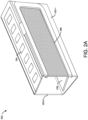
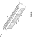
- the device 200 may include a housing 202 defining the shape of the device 200, which may be adapted to be fitted at the air inlet 114-1 of the cabinet.
- the device 200 may include one or more inlets or openings 204 at a top end and/or top rear end and/or top front end of the housing 202 which may have a predefined size based on the size of the objects to be allowed to be collected within the device 200 or to be restricted from entering the device 200.
- the device 200 may include the air filter 206 configured with a first wall 202-1 of the housing 202. A portion of the first wall 202-1 may be removed to form a frame to accommodate the air filter 206 thereon.
- multiple cut-outs may be formed on the first wall 202-1 to fit multiple air filters 206 to the housing 202.
- the air filter 206 may be removably fitted to the first wall 202-1 of the housing 202, however, in other embodiments, the air filter 206 may be fixedly integrated into the first wall 202-1 of the housing 202.
- the filter 206 may clean/filter the incoming air (received through the air inlet 114-1) and may further supply clean filtered air within the duct 108 for further cooling by a refrigeration or cooling system.
- the housing 202 may have a predefined dimension corresponding to the shape and size of the air inlet 114-1 at the bottom front of the cabinet 100 such that upon fitting the device 200 at the air inlet 114-1, the air filter 206 may face the duct 108 and the inlets 204 of the device 200 may face the conservation space 106 and/or an air curtain area 118 associated with the cabinet 100. Further, the size of the device 200 may be small enough to be cleaned in any commercial or industrial dish-washer. The device 200 may receive and collect the objects and/or liquids spilled from the conservation space 106 within the housing 202 via the inlets 204.
- the device 200 may further allow the inflow of air associated with the air curtain 118 within the housing 202 via the inlets 204, and supply the air into the duct 108 via the air filter 206 to filter particulates from the air and correspondingly supply filtered air into the duct 108.
- multiple devices 200 may be installed sequentially at the air inlet 114-1 of the cabinet 100 to cover an entire length of the air inlet 114-1 and such that the air filter 206 of each device 200 may face the duct 108 and the inlets 204 of the devices 200 may face the conservation space 106 and/or an air curtain area 118 associated with the cabinet 100.
- the device 200 may include an inclined member 208 extending across the width of the housing 202 and positioned below the air filter 206 within the housing 202 such that a predefined gap (G) remains between a free end of the inclined member 208 and a second wall 202-2, opposite to the air filter 206 or the first wall 202-1, of the housing 202.
- the member 208 may be inclined at a predefined angle from a horizontal plane in a downward direction to facilitate automated movement of the received object and liquids towards the bottom end of the housing 202 through the gap G such that the received object and liquids are collected and secured at the bottom end of the housing 202 under the inclined member 208, without any interaction with the air filter 206.
- the inclined member 208 may isolate the received/incoming air from the object and/or liquids that are collected at the bottom end of the housing 202 and/or further facilitate the received air to flow through the air filter 206 into the duct 108.
- the device 200 may include an inclined member comprising perforations.
- the inclined member may extend across a width of the housing 202 and is positioned below the air filter 206 within the housing 202, with or without any gap between the inclined member and the walls 202-1, 202-2 of the housing 202.
- the inclined member may be inclined at a predefined angle from a horizontal plane in a downward direction and/or an upward direction, to facilitate automated movement of the received object and liquids towards the bottom end of the housing 202 through the perforations such that the received object and liquids are collected and secured at the bottom end of the housing 202 under the inclined member 208, without any interaction with the air filter 206.
- the device 200 may include an outlet that allows the removal or discharge of the collected particulates, objects, and/or liquids from the housing 202.
- the particulates, objects, and liquids discharged from the device may be transferred to a collector tray 122 that may be positioned below the device 200.
- a meshed grid may be provided on the outlet to facilitate the removal or discharge of the collected liquids from the housing 202 while restricting the discharge of the collected object and/or particulates from the housing 202.
- the housing 202 may include an over-flow hole that may be provided at least below a bottom end of the air filter 206. This may prevent any interaction of the collected liquid with the air filter 206 in an event of overflow within the device 200.
- the cabinet 100 may be an open-type cabinet 100 (without any doors) as shown in FIG. 1A where an aerothermodynamic barrier may be created in front of cabinet 100 by a recirculating air curtain 118 extending between the air outlet 114-2 and the air inlet 114-1 which may keep the conservation space 106 and the environment thermally isolated.
- the cabinet 100 may be a door-type cabinet 100 as shown in FIG. 1B that may include multiple doors 120 (collectively referred to as doors, herein) movably coupled to the front of case 102.
- the doors 120 may be adapted to move between an open position and a closed position.
- the doors 120 and/or the aerothermodynamic barrier created in front of the cabinet 100 by a recirculating air curtain 118 may keep the conservation space 106 and the environment thermally isolated.
- the air inlet 114-1 of the duct 108 may be at a region between the front end of the bottommost shelf 104-N and the rear side of the doors 120.
- the device 200 may be fitted in the air inlet 114-1 such that the air filter 206 of the device 200 may face the duct 108 and the inlets 204 of the device 200 may face the conservation space 106 and/or the air curtain 118 formed between the shelves 104 and the doors 120.
- the device 200 may be configured at the air inlet 114-1 under the RAG of the cabinet 100.
- the device 200 may be integrated with the RAG of the cabinet 100, and all such embodiments are within the scope of this invention which is as defined in the appended claims.
- the refrigeration system may further include an evaporator comprising a heat exchanger 110 operable to enable heat exchange between the cool refrigerant and incoming clean air stream supplied by the device 200 to cool the air to a predefined temperature, which may be supplied to the conservation space 106 and/or create the cool air curtain 118 in front of the shelves 104.
- an evaporator comprising a heat exchanger 110 operable to enable heat exchange between the cool refrigerant and incoming clean air stream supplied by the device 200 to cool the air to a predefined temperature, which may be supplied to the conservation space 106 and/or create the cool air curtain 118 in front of the shelves 104.
- the refrigeration system may include a fan 112 that may be positioned adjacent (upstream or downstream) to the heat exchanger 110 within duct 108.
- the fan 112 may be configured to facilitate the inflow of air within duct 108 through the device 200 at the inlet 114-1 or RAG where the air may get filtered and pass through the heat exchanger 110 that may cool the filtered air and pump out the cool filtered air from the air outlet 114-2 or DAG of the cabinet 100.
- the cool filtered air pumped out by the DAG or air outlet 114-2 may be received by the RAG or air inlet 114-1 (on the bottom front side of cabinet 100) to create a curtain 118 of cool air in front of the shelves 104 or behind the doors 120 of the cabinet 100, which acts as an aerothermodynamic barrier between the conservation space 106 and environment.
- the second section of duct 108 on the rear side of cabinet 100 may include perforated wall panels (PWP) 116 behind the shelves 104, which may discharge a portion of the cool filtered air, passing through duct 108, into the conservation space 106 to maintain the predefined temperature within the cabinet 100.
- PWP perforated wall panels
- the bottom airflow zone 108-1 of duct 108 may act as a return air duct that may extend substantially along a horizontal axis and is formed below the lowest shelf of cabinet 100.
- the bottom airflow zone 108-1 or the rear airflow zone 108-2 may house the fan 112 that may be configured to suck air from the conservation space 106 through the device 200 located at the air inlet 114-1 or RAG into the bottom airflow zone 108-1 where the filter 206 of the device 200 may clean the air by collecting particulates and deliver clean air to the evaporator/heat exchanger 110 where it is cooled.
- the device 200 may further prevent the objects or liquids/spillage of the conservation space 106 from falling into duct 108 or bottom airflow zone 108-1, which may later be removed from the device 200.
- At least one wall of the housing 202 may be removable from the housing 202 to provide access to the interior of the device 200 and/or facilitate cleaning of the device 200 interior.
- the housing 202 may comprise a handle 210, and a locking mechanism 212 configured between the housing 202 and the removable wall of the device 200.
- the locking mechanism 212 in a locked position may keep the removable wall attached to the housing 202 and may allow users to remove the device 200 from the air inlet 114-1 and easily carry the device 200 using the handle 210.
- the locking mechanism 212 in an unlocked position may allow the users to separate the wall from the housing 202 to access the interior of the device 200 and further facilitate the cleaning of the interior of the device 200.
- the device 200 may be configured with a self-cleaning system (not shown) that may automatically clean the filter 206 and/or the interior of the device 200.
- the self-cleaning system may include one or more nozzles fluidically connected to a cleaning fluid source via a pump.
- the fluid source may store cleaning fluids selected from water, air, liquid soap, and the like.
- the self-cleaning system upon actuation, may be configured to supply, through the nozzles, a stream of cleaning fluid over the air filter 206 and/or interior walls of the housing 202 to facilitate the cleaning of the air filter 206 and/or interior of the device 200.
- any collected fluid or dirt left in the housing 202 after the cleaning of the device 200 may be discharged out of the device 200 into the collector (when the device 200 is fitted in the cabinet 100) or outside (when the device 200 is removed from the cabinet 100) through the outlet provided at the bottom of the housing 202.
- the device 200 may include one or more first sensors configured within and/or outside the housing 202 to monitor one or more of the presence, weight, volume, and level of the objects and/or the liquids collected within the housing 202.
- the first sensors may comprise one or more of an optical sensor, a weight sensor, a proximity sensor, and the like.
- the device 200 may comprise one or more second sensors configured with the air filter 206 to monitor the health of the air filter 206 or the level of particulates or the concentration of contaminants collected in the air filter 206.
- the second sensors may comprise one or more of a pressure sensor, a particulate sensor, a contaminant sensor, a volatile organic compound sensor, and the like.
- the device 200 may comprise one or more third sensors configured within the housing 202 to detect/check the occurrence of one or more chemical reactions within the housing 202, which may generally occur due to the degradation or interaction between the collected objects, and liquids.
- the third sensors may be chemical sensors comprising one or more of thermal sensors, mass sensors, electrochemical sensors, optical sensors, and the like.
- the device 200 may comprise a control unit in communication with the first sensors, the second sensors, the third sensors, and the self-cleaning system.
- the control unit may comprise a processor coupled to a memory storing instructions executable by the processor.
- the control unit may be configured with a communication module known in the art to communicatively couple the device 200 to one or more mobile devices and/or a remote monitoring system of the users associated with the cabinet, and/or a controller and/or a display device associated with the cabinet where the device 200 is installed.
- the users may be owner, maintenance contracts, and the like associated with the cabinet.
- the control unit may be configured to receive the data collected by the first sensors, the second sensors, and/or the third sensors in real time and also store the collected data in a cloud database.
- the control unit may be configured to generate and transmit a first set of alert signals to the mobile devices of users, and/or the controller and the display device 200 of the cabinet when the weight, volume, and/or level of the objects and/or the liquids collected within the housing 202 exceeds the first predefined values.
- the control unit may be configured to generate and transmit a second set of alert signals to the mobile devices of users, and/or the controller and the display device of the cabinet 100 upon detection of the occurrence of the chemical reactions within the housing 202.
- the control unit may be configured to actuate the self-cleaning system to clean the air filter 206 when the level of particulates collected in the air filter 206 exceeds a second predefined value. Further, the control unit may be configured to actuate the self-cleaning system to clean the interior of the device 200 when the level of objects and/or liquids collected in the housing 202 exceeds the first predefined values and/or when the occurrence of a chemical reaction is detected within the device 200.
- the device 200 may include a level indicator to indicate the level of liquids or objects collected within the device 200.
- the level indicator may be visible to users from the outside of the device 200 and/or cabinet 100. This may allow users to empty and clean the device 200 before their level exceed the first predefined values.
- the level indicator may be a mechanical indicator configured within the device 200 which may provide a visual indication about the level of the collected liquids and objects from outside of the device 200.
- the level indicator may involve the first sensors that may monitor the level of the collected liquids and objects within the device 200 and correspondingly actuate the control unit to display the monitored level on the mobile devices of the user and/or the display device associated with the cabinet.
- this invention overcomes the drawbacks, shortcomings, and limitations associated with existing cabinets by providing a device that may be easily installed at the air inlet associated with the airflow channel/duct of the cabinet to restrict the entry of particulates, objects, and/or liquid within the duct. Moreover, the device may supply clean filtered air within the duct and further allow easier collection and removal of the particulates, objects, and liquid from the device. In addition, the device is also equipped with a self-cleaning system that may clean the interior of the device either upon manual actuation by users or when the level/weight of the collected liquid or objects exceeds a threshold level, or upon detection of the occurrence of chemical reactions within the device. This may help keep the device clean and hygienic. Further, the device may monitor the health of the air filter and may further clean the filters using the self-cleaning system and/or alert users about replacement or cleaning the filters.
Landscapes
- Engineering & Computer Science (AREA)
- Physics & Mathematics (AREA)
- Thermal Sciences (AREA)
- Chemical & Material Sciences (AREA)
- Combustion & Propulsion (AREA)
- Mechanical Engineering (AREA)
- General Engineering & Computer Science (AREA)
- Cold Air Circulating Systems And Constructional Details In Refrigerators (AREA)
Applications Claiming Priority (1)
| Application Number | Priority Date | Filing Date | Title |
|---|---|---|---|
| US202363508943P | 2023-06-19 | 2023-06-19 |
Publications (1)
| Publication Number | Publication Date |
|---|---|
| EP4480352A1 true EP4480352A1 (de) | 2024-12-25 |
Family
ID=91582058
Family Applications (1)
| Application Number | Title | Priority Date | Filing Date |
|---|---|---|---|
| EP24182683.3A Pending EP4480352A1 (de) | 2023-06-19 | 2024-06-17 | Vorrichtung für den lufteinlass von gekühlten schaukästen zum sammeln von partikeln, objekten und flüssigkeiten |
Country Status (2)
| Country | Link |
|---|---|
| US (1) | US20240415298A1 (de) |
| EP (1) | EP4480352A1 (de) |
Citations (3)
| Publication number | Priority date | Publication date | Assignee | Title |
|---|---|---|---|---|
| JPH0791807A (ja) * | 1993-09-21 | 1995-04-07 | Sanyo Electric Co Ltd | ショーケース |
| JP2005034304A (ja) * | 2003-07-18 | 2005-02-10 | Sanden Corp | ショーケース |
| JP2017131369A (ja) * | 2016-01-27 | 2017-08-03 | 東芝キヤリア株式会社 | オープンショーケース |
Family Cites Families (6)
| Publication number | Priority date | Publication date | Assignee | Title |
|---|---|---|---|---|
| JP2004245569A (ja) * | 2003-01-22 | 2004-09-02 | Nakano Refrigerators Co Ltd | 冷凍機内蔵型ショーケース |
| KR101813030B1 (ko) * | 2010-12-29 | 2017-12-28 | 엘지전자 주식회사 | 냉장고 |
| US20120291458A1 (en) * | 2011-05-18 | 2012-11-22 | Seibert Roy E | Apparatus and Method for Inhibiting the Growth of Microbiological Organisms in Commercial Icemakers and Coolers |
| KR102575475B1 (ko) * | 2018-04-17 | 2023-09-07 | 서울바이오시스 주식회사 | 공기 정화 모듈 및 이를 포함하는 냉장고 |
| JP7361292B2 (ja) * | 2019-03-29 | 2023-10-16 | 株式会社コーワ | フィルター清掃装置及びショーケース |
| CN111318090B (zh) * | 2020-03-06 | 2021-07-20 | 黑龙江建筑职业技术学院 | 一种制冷设备空气过滤装置的自清洗结构 |
-
2024
- 2024-06-10 US US18/738,114 patent/US20240415298A1/en active Pending
- 2024-06-17 EP EP24182683.3A patent/EP4480352A1/de active Pending
Patent Citations (3)
| Publication number | Priority date | Publication date | Assignee | Title |
|---|---|---|---|---|
| JPH0791807A (ja) * | 1993-09-21 | 1995-04-07 | Sanyo Electric Co Ltd | ショーケース |
| JP2005034304A (ja) * | 2003-07-18 | 2005-02-10 | Sanden Corp | ショーケース |
| JP2017131369A (ja) * | 2016-01-27 | 2017-08-03 | 東芝キヤリア株式会社 | オープンショーケース |
Also Published As
| Publication number | Publication date |
|---|---|
| US20240415298A1 (en) | 2024-12-19 |
Similar Documents
| Publication | Publication Date | Title |
|---|---|---|
| CN107615315B (zh) | 用于食物吧布置设备的监视和控制系统及食物吧布置设备 | |
| RU2667870C2 (ru) | Полка с воздуховодом для прилавка-витрины с открытой передней частью (варианты) | |
| CN101160078A (zh) | 模块化制冷盒 | |
| EP1570772B1 (de) | Verkaufskühlmöbel mit einem Reinigungszugang | |
| EP3205950B1 (de) | Klimagerät mit kondensatsammelvorrichtung | |
| GB2295222A (en) | Refrigerated display case | |
| JP6755929B2 (ja) | オープンショーケース | |
| EP4480352A1 (de) | Vorrichtung für den lufteinlass von gekühlten schaukästen zum sammeln von partikeln, objekten und flüssigkeiten | |
| US7600388B2 (en) | Refrigerator with an air filter/freshener system | |
| JP4960797B2 (ja) | 冷凍冷蔵倉庫用のラック及びエアカーテン装置の運転方法 | |
| CN101179965A (zh) | 冷藏商品柜的底板组件 | |
| US4603557A (en) | Refrigerated-goods display case | |
| EP2071259A2 (de) | Filter | |
| EP3699521A1 (de) | Eintrittskühlschrank | |
| WO2014191034A1 (en) | Refrigerated sales furniture | |
| EP3699526B1 (de) | Eintrittskühlschrank | |
| JP2005009836A (ja) | 貯蔵庫 | |
| JP2018068836A (ja) | リーチイン型の貯蔵庫 | |
| EP3792181B1 (de) | Verwaltung des kondensatabflusses in einem kühlluftkanal | |
| JP2715363B2 (ja) | エアカーテン式冷蔵ショーケース | |
| JP2017131369A (ja) | オープンショーケース | |
| EP2194819B1 (de) | Kühlverkaufsmöbel | |
| US20040007948A1 (en) | Goods display cabinet | |
| JP2013205005A (ja) | ショーケースの清掃装置 | |
| JP6055693B2 (ja) | 貯蔵庫 |
Legal Events
| Date | Code | Title | Description |
|---|---|---|---|
| PUAI | Public reference made under article 153(3) epc to a published international application that has entered the european phase |
Free format text: ORIGINAL CODE: 0009012 |
|
| STAA | Information on the status of an ep patent application or granted ep patent |
Free format text: STATUS: THE APPLICATION HAS BEEN PUBLISHED |
|
| AK | Designated contracting states |
Kind code of ref document: A1 Designated state(s): AL AT BE BG CH CY CZ DE DK EE ES FI FR GB GR HR HU IE IS IT LI LT LU LV MC ME MK MT NL NO PL PT RO RS SE SI SK SM TR |
|
| STAA | Information on the status of an ep patent application or granted ep patent |
Free format text: STATUS: REQUEST FOR EXAMINATION WAS MADE |
|
| 17P | Request for examination filed |
Effective date: 20250624 |
|
| GRAP | Despatch of communication of intention to grant a patent |
Free format text: ORIGINAL CODE: EPIDOSNIGR1 |
|
| STAA | Information on the status of an ep patent application or granted ep patent |
Free format text: STATUS: GRANT OF PATENT IS INTENDED |
|
| RIC1 | Information provided on ipc code assigned before grant |
Ipc: A47F 3/04 20060101AFI20251030BHEP Ipc: B01D 45/08 20060101ALN20251030BHEP |
|
| RIC1 | Information provided on ipc code assigned before grant |
Ipc: A47F 3/04 20060101AFI20251103BHEP Ipc: B01D 45/08 20060101ALN20251103BHEP |
|
| INTG | Intention to grant announced |
Effective date: 20251113 |
|
| GRAJ | Information related to disapproval of communication of intention to grant by the applicant or resumption of examination proceedings by the epo deleted |
Free format text: ORIGINAL CODE: EPIDOSDIGR1 |
|
| STAA | Information on the status of an ep patent application or granted ep patent |
Free format text: STATUS: REQUEST FOR EXAMINATION WAS MADE |
|
| GRAP | Despatch of communication of intention to grant a patent |
Free format text: ORIGINAL CODE: EPIDOSNIGR1 |
|
| STAA | Information on the status of an ep patent application or granted ep patent |
Free format text: STATUS: GRANT OF PATENT IS INTENDED |
|
| INTC | Intention to grant announced (deleted) | ||
| RIC1 | Information provided on ipc code assigned before grant |
Ipc: A47F 3/04 20060101AFI20260319BHEP Ipc: B01D 45/08 20060101ALN20260319BHEP |