EP4478086A1 - Informationsverarbeitungsvorrichtung, steuerungsverfahren, programm und speichermedium - Google Patents
Informationsverarbeitungsvorrichtung, steuerungsverfahren, programm und speichermedium Download PDFInfo
- Publication number
- EP4478086A1 EP4478086A1 EP22925891.8A EP22925891A EP4478086A1 EP 4478086 A1 EP4478086 A1 EP 4478086A1 EP 22925891 A EP22925891 A EP 22925891A EP 4478086 A1 EP4478086 A1 EP 4478086A1
- Authority
- EP
- European Patent Office
- Prior art keywords
- point cloud
- cloud information
- fluctuation
- point
- information processing
- Prior art date
- Legal status (The legal status is an assumption and is not a legal conclusion. Google has not performed a legal analysis and makes no representation as to the accuracy of the status listed.)
- Pending
Links
Images


Classifications
-
- G—PHYSICS
- G01—MEASURING; TESTING
- G01S—RADIO DIRECTION-FINDING; RADIO NAVIGATION; DETERMINING DISTANCE OR VELOCITY BY USE OF RADIO WAVES; LOCATING OR PRESENCE-DETECTING BY USE OF THE REFLECTION OR RERADIATION OF RADIO WAVES; ANALOGOUS ARRANGEMENTS USING OTHER WAVES
- G01S7/00—Details of systems according to groups G01S13/00, G01S15/00, G01S17/00
- G01S7/48—Details of systems according to groups G01S13/00, G01S15/00, G01S17/00 of systems according to group G01S17/00
- G01S7/497—Means for monitoring or calibrating
-
- G—PHYSICS
- G01—MEASURING; TESTING
- G01S—RADIO DIRECTION-FINDING; RADIO NAVIGATION; DETERMINING DISTANCE OR VELOCITY BY USE OF RADIO WAVES; LOCATING OR PRESENCE-DETECTING BY USE OF THE REFLECTION OR RERADIATION OF RADIO WAVES; ANALOGOUS ARRANGEMENTS USING OTHER WAVES
- G01S17/00—Systems using the reflection or reradiation of electromagnetic waves other than radio waves, e.g. lidar systems
- G01S17/88—Lidar systems specially adapted for specific applications
- G01S17/89—Lidar systems specially adapted for specific applications for mapping or imaging
-
- G—PHYSICS
- G01—MEASURING; TESTING
- G01S—RADIO DIRECTION-FINDING; RADIO NAVIGATION; DETERMINING DISTANCE OR VELOCITY BY USE OF RADIO WAVES; LOCATING OR PRESENCE-DETECTING BY USE OF THE REFLECTION OR RERADIATION OF RADIO WAVES; ANALOGOUS ARRANGEMENTS USING OTHER WAVES
- G01S17/00—Systems using the reflection or reradiation of electromagnetic waves other than radio waves, e.g. lidar systems
- G01S17/02—Systems using the reflection of electromagnetic waves other than radio waves
- G01S17/06—Systems determining position data of a target
- G01S17/08—Systems determining position data of a target for measuring distance only
- G01S17/10—Systems determining position data of a target for measuring distance only using transmission of interrupted, pulse-modulated waves
-
- G—PHYSICS
- G01—MEASURING; TESTING
- G01S—RADIO DIRECTION-FINDING; RADIO NAVIGATION; DETERMINING DISTANCE OR VELOCITY BY USE OF RADIO WAVES; LOCATING OR PRESENCE-DETECTING BY USE OF THE REFLECTION OR RERADIATION OF RADIO WAVES; ANALOGOUS ARRANGEMENTS USING OTHER WAVES
- G01S17/00—Systems using the reflection or reradiation of electromagnetic waves other than radio waves, e.g. lidar systems
- G01S17/02—Systems using the reflection of electromagnetic waves other than radio waves
- G01S17/06—Systems determining position data of a target
- G01S17/42—Simultaneous measurement of distance and other co-ordinates
-
- G—PHYSICS
- G01—MEASURING; TESTING
- G01S—RADIO DIRECTION-FINDING; RADIO NAVIGATION; DETERMINING DISTANCE OR VELOCITY BY USE OF RADIO WAVES; LOCATING OR PRESENCE-DETECTING BY USE OF THE REFLECTION OR RERADIATION OF RADIO WAVES; ANALOGOUS ARRANGEMENTS USING OTHER WAVES
- G01S17/00—Systems using the reflection or reradiation of electromagnetic waves other than radio waves, e.g. lidar systems
- G01S17/86—Combinations of lidar systems with systems other than lidar, radar or sonar, e.g. with direction finders
-
- G—PHYSICS
- G01—MEASURING; TESTING
- G01S—RADIO DIRECTION-FINDING; RADIO NAVIGATION; DETERMINING DISTANCE OR VELOCITY BY USE OF RADIO WAVES; LOCATING OR PRESENCE-DETECTING BY USE OF THE REFLECTION OR RERADIATION OF RADIO WAVES; ANALOGOUS ARRANGEMENTS USING OTHER WAVES
- G01S17/00—Systems using the reflection or reradiation of electromagnetic waves other than radio waves, e.g. lidar systems
- G01S17/88—Lidar systems specially adapted for specific applications
- G01S17/93—Lidar systems specially adapted for specific applications for anti-collision purposes
- G01S17/931—Lidar systems specially adapted for specific applications for anti-collision purposes of land vehicles
-
- G—PHYSICS
- G01—MEASURING; TESTING
- G01S—RADIO DIRECTION-FINDING; RADIO NAVIGATION; DETERMINING DISTANCE OR VELOCITY BY USE OF RADIO WAVES; LOCATING OR PRESENCE-DETECTING BY USE OF THE REFLECTION OR RERADIATION OF RADIO WAVES; ANALOGOUS ARRANGEMENTS USING OTHER WAVES
- G01S7/00—Details of systems according to groups G01S13/00, G01S15/00, G01S17/00
- G01S7/48—Details of systems according to groups G01S13/00, G01S15/00, G01S17/00 of systems according to group G01S17/00
- G01S7/4808—Evaluating distance, position or velocity data
-
- G—PHYSICS
- G01—MEASURING; TESTING
- G01S—RADIO DIRECTION-FINDING; RADIO NAVIGATION; DETERMINING DISTANCE OR VELOCITY BY USE OF RADIO WAVES; LOCATING OR PRESENCE-DETECTING BY USE OF THE REFLECTION OR RERADIATION OF RADIO WAVES; ANALOGOUS ARRANGEMENTS USING OTHER WAVES
- G01S7/00—Details of systems according to groups G01S13/00, G01S15/00, G01S17/00
- G01S7/48—Details of systems according to groups G01S13/00, G01S15/00, G01S17/00 of systems according to group G01S17/00
- G01S7/481—Constructional features, e.g. arrangements of optical elements
- G01S7/4817—Constructional features, e.g. arrangements of optical elements relating to scanning
-
- G—PHYSICS
- G01—MEASURING; TESTING
- G01S—RADIO DIRECTION-FINDING; RADIO NAVIGATION; DETERMINING DISTANCE OR VELOCITY BY USE OF RADIO WAVES; LOCATING OR PRESENCE-DETECTING BY USE OF THE REFLECTION OR RERADIATION OF RADIO WAVES; ANALOGOUS ARRANGEMENTS USING OTHER WAVES
- G01S7/00—Details of systems according to groups G01S13/00, G01S15/00, G01S17/00
- G01S7/48—Details of systems according to groups G01S13/00, G01S15/00, G01S17/00 of systems according to group G01S17/00
- G01S7/497—Means for monitoring or calibrating
- G01S7/4972—Alignment of sensor
Definitions
- Patent Literature 1 discloses a forward vehicle recognition device for detecting the distance to the forward vehicle and the inclination by changing the lighting pattern for the projecting a patterned light based on the detection state of the patterned light.
- Patent Literature 1 JP 2008-082750A
- the above-described issue is an example of the issues which the present disclosure has been made to solve, and it is an example object of the present invention to provide an information processing device, a control method, a program, and a storage medium storing a program capable of suitably processing the point cloud information outputted by a measurement device even when there is a fluctuation in the measurement device.
- One invention is an information processing device including: an acquisition means configured to acquire point cloud information, which is a set of data representing a point measured for each measurement direction by a measurement device;
- Another invention is a control method executed by a computer, the control method including:
- Still another invention is a program causing a computer to:
- the information processing device includes: an acquisition means configured to acquire point cloud information, which is a set of data representing a point measured for each measurement direction by a measurement device; a detection means configured to detect a predetermined degree or more of fluctuation in the measurement device; and a processing means configured to determine, based on whether the fluctuation is detected or not, a search range for searching for a point of second point cloud information which corresponds to each point of first point cloud information, wherein the first point cloud information is the point cloud information obtained at a current processing time and the second point cloud information is the point cloud information obtained at a preceding processing time.
- the information processing device can suitably set the search range having an accurate correspondence between the first point cloud information corresponding to the current processing time and the second point cloud information corresponding to the preceding processing time.
- the processing means upon detecting the fluctuation, is configured to expand the search range in a direction in which the fluctuation occurred. According to this aspect, the information processing device can set the search range having an accurate correspondence between the first point cloud information and the second point cloud information, based on the direction in which the fluctuation occurred.
- the detection means is configured to detect the fluctuation in at least one of a pitch direction, a yaw direction and/or a roll direction of the measurement device.
- the information processing device can set the search range in accordance with the fluctuation in the pitch direction, the yaw direction, or the roll direction of the measurement device.
- the processing means is configured to detect the direction of the fluctuation among positive directions or negative directions of the pitch direction, the yaw direction, or the roll direction, and expand the search range in a direction opposite to the detected direction.
- the information processing device can expand the search range in a necessary direction when the fluctuation is detected.
- the detection means is configured to detect the fluctuation based on the first point cloud information and the second point cloud information. In a preferred embodiment, the detection means is configured to detect the fluctuation based on a matching result between the first point cloud information and the second point cloud information based on ground points which are the points representing a ground. In another preferred embodiment, the detection means is configured to detect the fluctuation based on a matching result between the first point cloud information and the second point cloud information based on the points representing measurement distances equal to or longer than a predetermined distance. With these aspects, the information processing device can preferably detect the fluctuation of the measurement device.
- the detection means is configured to detect the fluctuation based on a detection signal outputted by a sensor, which is provided in the measurement device or a moving object in which the measurement device is provided.
- the information processing device can preferably detect the fluctuation of the measurement device.
- a control method executed by an information processing device including: acquiring point cloud information, which is a set of data representing a point measured for each measurement direction by a measurement device; detecting a predetermined degree or more of fluctuation in the measurement device; and determining, based on whether the fluctuation is detected or not, a search range for searching for a point of second point cloud information which corresponds to each point of first point cloud information, wherein the first point cloud information is the point cloud information obtained at a current processing time and the second point cloud information is the point cloud information obtained at a preceding processing time.
- the information processing device can suitably set the search range having an accurate correspondence between the first point cloud information corresponding to the current processing time and the second point cloud information corresponding to the preceding processing time.
- a program causing a computer to: acquire point cloud information, which is a set of data representing a point measured for each measurement direction by a measurement device; detect a predetermined degree or more of fluctuation in the measurement device; and determine, based on whether the fluctuation is detected or not, a search range for searching for a point of second point cloud information which corresponds to each point of first point cloud information, wherein the first point cloud information is the point cloud information obtained at a current processing time and the second point cloud information is the point cloud information obtained at a preceding processing time.
- the computer can suitably set the search range having an accurate correspondence between the first point cloud information corresponding to the current processing time and the second point cloud information corresponding to the preceding processing time.
- the program is stored in a storage medium.
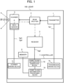
- FIG. 1 shows a schematic configuration of a lidar 100 according to the first embodiment.
- the lidar 100 is, for example, mounted on a vehicle that performs driving support such as autonomous driving.
- the lidar 100 radiates the laser light with respect to a predetermined angle range in the horizontal and vertical directions, and by receiving the returned light (also referred to as "reflected light") which is the laser light reflected at an object, the lidar 100 discretely measures the distance from the lidar 100 to the object and generates point cloud information indicating three-dimensional positions of the object.
- the lidar 100 mainly includes a transmitter 1, a receiver 2, a beam splitter 3, a scanner 5, a piezo sensor 6, a controller 7, and a memory 8.
- the transmitter 1 is a light source configured to emit a pulsed laser light toward the beam splitter 3.
- the transmitter 1 includes an infrared laser emitting element.
- the transmitter 1 is driven based on the driving signal "Sg1" supplied from the controller 7.
- the receiver 2 is, for example, an avalanche photodiode (Avalanche Photo-Diode), and generates a detection signal "Sg2" corresponding to the amount of received light, and supplies the generated detection signal Sg2 to the controller 7.
- avalanche photodiode Avalanche Photo-Diode
- the beam splitter 3 is transparent to the pulsed laser light emitted from the transmission unit 1. In contrast, the beam splitter 3 reflects the light reflected by the scanner 5 toward the receiver 2.
- the scanner 5 is, for example, a mirror (MEMS mirror) according to an electrostatic drive system, based on the driving signal "Sg3" supplied from the controller 7, the inclination (i.e., the optical scanning angle) of the scanner 5 is changed within a predetermined range. Then, the scanner 5 reflects the laser light, which passed through the beam splitter 3, toward the outside of the lidar 100, and reflects the reflected light incident from the outside of the lidar 100 toward the beam splitter 3. Further, a point, or its measurement data, measured through irradiation with the laser light within the measurement range of the lidar 100 is also referred to as "measured point".
- the scanner 5 is also provided with the piezo sensor 6.
- the piezo sensor 6 detects the strain caused by the stress of the torsion bar which supports the mirror part of the scanner 5.
- the piezo sensor 6 supplies the generated detection signal "Sg4" to the controller 7.
- the detection signal Sg4 is used to detect the orientation of the scanners 5.
- the memory 8 is configured by various volatile memories such as a RAM (Random Access Memory), a ROM (Read Only Memory), a flash memory, and a non-volatile memory.
- the memory 8 stores a program which is necessary for the controller 7 to execute a predetermined process.
- the memory 8 stores various parameters referred to by the controller 7. Further, the memory 8 stores point cloud information equivalent to a predetermined number of latest frames generated by the controller 7.
- the controller 7 includes various processors such as a CPU (Central Processing Unit) and a GPU (Graphics Processing Unit).
- the controller 7 executes a program stored in the memory 8 to execute a predetermined process.
- the controller 7 is an example of a computer for executing a program.
- the controller 7 is not limited to be implemented by software using a program, it may be implemented by any combination of hardware, firmware, software and/or the like.
- the controller 7 may also be a user-programmable integrated-circuit, such as a FPGA (Field-Programmable Gate Array) and a microcontroller, an ASSP (Application Specific Standard Produce) and an ASIC (Application Specific Integrated Circuit).
- FPGA Field-Programmable Gate Array
- ASSP Application Specific Standard Produce
- ASIC Application Specific Integrated Circuit
- the controller 7 functionally includes a transmission driving block 70, a scanner driving block 71, a point cloud information generation block 72, and a point cloud information processing block 73.
- the transmission driving block 70 outputs a driving signal Sg1 for driving the transmitter 1.
- the driving signal Sg1 includes information regarding a light emission time of the laser light emitting element included in the transmitter 1 and information for controlling the emission intensity of the laser light emitting element. Based on the driving signal Sg1, the transmission driving block 70 controls the emission intensity of the laser light emitting element included in the transmitter 1.
- the scanner driving block 71 outputs a driving signal Sg3 for driving the scanner 5.
- the driving signal Sg3 includes a horizontal driving signal corresponding to the resonant frequency of the scanner 5 and a vertical driving signal for vertical scanning.
- the scanner driving block 71 also detects the scan angle of the scanner 5 (i.e., the emission direction of the laser light) by monitoring the detection signal Sg4 outputted from the piezo sensor 6.
- the point cloud information generation block 72 Based on the detection signal Sg2 supplied from the receiver 2, the point cloud information generation block 72 generates point cloud information indicative of, with respect to each measurement direction (i.e., emitting direction of the laser light), a distance (measurement distance) from the lidar 100, which is a reference point, to an object irradiated with the laser light. In this case, the point cloud information generation block 72 calculates, as the time of flight (Time of Flight) of the light, the time from the emission of the laser light to the detection of the reflected light by the receiver 2.
- the time of flight Time of Flight
- the point cloud information generation block 72 generates point cloud information which indicates a set of points each corresponding to a combination of: the measurement distance in accordance with the calculated time of flight; and the emitting direction (measurement direction) of the laser light received as the reflected light by the receiver 2. Then, the point cloud information generation block 72 supplies the generated point cloud information to the point cloud information processing block 73.
- point cloud information obtained in one cycle of the scanning for all measured points is also referred to as a frame of point cloud information.
- the point cloud information can be regarded as an image, wherein each pixel of the image corresponds to each measurement direction and the pixel value of the each pixel is set as the measurement distance in the each measurement direction.
- pixels arranged in the vertical direction correspond to different emitting directions of the laser light in the elevation / depression angle and pixels arranged in the horizontal direction correspond to different emitting directions of the laser light in the horizontal angle. Then, the coordinate value, in the three-dimensional coordinate system with reference to the lidar 100, of each pixel is obtained based on a combination of the corresponding emitting direction and measurement distance.
- the point cloud information processing block 73 removes noise data (false alarm data) generated by erroneously detecting an object in the point cloud information.
- noise data false alarm data
- any measured point corresponding to data generated by detecting an existing object is referred to as "valid point”
- any measured point i.e., the measured point corresponding to the noise data which is not a valid point
- the point cloud information processing block 73 searches for measured points having a correspondence between the frame (also referred to as "current frame”) of the point cloud information obtained at the current processing time and a frame (also referred to as "past frame”) of the point cloud information obtained in the past, and determine whether or not each measured point is a valid point, based on the search result.
- the point cloud information processing block 73 expands the target range (search range) of search, thereby to accurately make the determination as to the valid points regardless of the presence or absence of the positional fluctuation of the lidar 100.
- the current frame is an example of the "first point cloud information”
- the past frame is an example of the "second point cloud information”.
- the point cloud information processing block 73 is an example of "acquisition means", “detection means” and “processing means”.
- the lidar 100 from which the point cloud information processing block 73 is excluded is an example of the "measurement device”.
- the point cloud information processing block 73 may add, to the point cloud information, flag information indicating whether or not each measured point is a valid point, instead of removing the noise data from the point cloud information. Further, the point cloud information processing block 73 may supplies the processed point cloud information to an external device existing outside the lidar 100 or to any other processing block in the lidar 100 for performing obstacle detection or the like. In the former case, for example, the point cloud information may be outputted to a device (also referred to as "driving support device") configured to control the driving support such as autonomous driving of a vehicle. In this case, for example, based on the point cloud information, the control of the vehicle may be performed so as to avoid at least the obstacle points.
- the driving support device may be an ECU (Electronic Control Unit) of the vehicle, or may be a vehicle-mounted device such as a car navigation device electrically connected to the vehicle.
- the point cloud information processing block 73 stores each frame of the point cloud information in the memory 8 in association with the time information indicating the processing time for each frame.
- the lidar 100 is not limited to a scan type lidar configured to scan the field of view with a laser light, and it may be a flash type lidar configured to generate three-dimensional data by diffusively radiating a laser light to the field of view of two-dimensional array structure sensor.
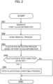
- FIG. 2 is an example of a flowchart illustrating a procedure of the process (point cloud information process) related to the point cloud information.
- the lidar 100 repeatedly executes the point cloud information process for each cycle of generating a frame of the point cloud information.
- the point cloud information generation block 72 Based on the detection signal Sg2, the point cloud information generation block 72 generates point cloud information (step S01). In this instance, the point cloud information generation block 72 generates the current frame of the point cloud information on the basis of the detection signal Sg2 generated during one-cycle scanning in the target area of scanning by the lidar 100.
- the point cloud information processing block 73 executes the noise removal process which is a process of removing the noise data from the point cloud information generated at step S01 (step S02).
- the point cloud information processing block 73 determines whether or not each measured point in the current frame is a valid point. For example, for each valid point in the past frame, the point cloud information processing block 73 sets a range (also referred to as "search range") for searching for measured points having a correspondence between the current frame and the past frame. Then, the point cloud information processing block 73 searches for such measured point(s) in the current frame that the difference in the measurement distance between the each valid point and the measured point is equal to or smaller than a predetermined distance difference.
- the point cloud information processing block 73 sets, as a valid point, any measured point in the current frame having a similar measurement distance to a predetermined number or more of the valid points in the past frame, while setting any other measured point as an invalid point.
- the search range herein i.e., which corresponds to the normal search range described below
- the search range is set without consideration of the fluctuation of the lidar 100 in the pitch direction.
- some measured points could be determined to be invalid points although they are actually valid points. Such measured points will be corrected to be valid points through pitch fluctuation compatible process to be described later.
- the point cloud information processing block 73 may perform any noise removal processing based on the current frame of the point cloud information, without using a past frame of the point cloud information. For example, the point cloud information processing block 73 may determine that any measured point, at which the intensity of the reflection light received by the receiving unit 2 is smaller than a predetermined threshold value, is a valid point. In another example, the point cloud information processing block 73 may apply a clustering method based on Euclidean distance to the measured points according to their measurement distances, and then determines that any measured point belonging to a cluster having less than a predetermined number of elements is an invalid point.
- the point cloud information processing block 73 executes the fluctuation detection process, which is the process of detecting the fluctuation in the pitch direction of the lidar 100, based on the point cloud information (step S03).
- the point cloud information processing block 73 accurately detects the fluctuation if the lidar 100 fluctuates in the pitch direction due to the passage of the vehicle through a bump or a step or the like.
- the point cloud information processing block 73 Upon detecting the fluctuation in the pitch direction through the fluctuation detection process (step S04; Yes), the point cloud information processing block 73 executes the pitch fluctuation compatible process that is a determination process as to the valid points on the assumption that there is a fluctuation in the pitch direction of the lidar 100 (step S05). In this case, the point cloud information processing block 73 sets a search range for searching for a measured point having a correspondence between the current frame and the past frame, and then, based on the search result in the search range, sets a part of the measured points, which were determined to be invalid points at step S02, to be valid points. On the other hand, if the fluctuation in the pitch direction is not detected through the fluctuation detection process (step S04; No), the point cloud information processing block 73 terminates the process of the flowchart.
- the point cloud information processing block 73 performs matching (registration) between the valid points in the past frame (e.g., the past frame at the preceding processing time) and the valid points in the current frame determined to be valid points in the noise removal process. Then, based on the result of the matching (registration result), upon determining that the variation width (i.e., the number of horizontal scanning lines, or, the shifted number of pixels in the vertical direction when the point cloud information is regarded as an image) in the pitch direction from the past frame is equal to or larger than a predetermined width, the point cloud information processing block 73 determines that there is a fluctuation in the pitch direction of the lidar 100.
- the variation width i.e., the number of horizontal scanning lines, or, the shifted number of pixels in the vertical direction when the point cloud information is regarded as an image
- the point cloud information processing block 73 may determine matching target (registration target) to be any one of the following: every valid point; measured points (referred to as "ground points") representing the ground; clusters generated based on clustering of valid points; or measured points corresponding to a detected object when an object detection process (instance segmentation, etc.) has been performed.
- the point cloud information processing block 73 may perform matching of the matching target based on an arbitrary matching method (optimization method) and calculate the above-described variation width.
- the point cloud information processing block 73 estimates a plane representing the ground based on the valid points determined in the noise removal process at step S02, and then determines valid points, which exist at positions higher than a predetermined threshold value from the plane, to be obstacle points while determining the other valid points as the ground points. Then, the point cloud information processing block 73 calculates the variation width between the ground points in the current frame and the ground points in the past frame.
- the point cloud information processing block 73 may use the entire field of view of the lidar 100 as the target space of the matching described above, or may uses a space apart therefrom by a predetermined distance or more. Generally, when there is a fluctuation in the pitch direction of the lidar 100, the above-described variation width in the pitch direction increases with increasing distance to an object. Therefore, for example, the point cloud information processing block 73 may apply the matching to valid points (or cluster or object) which satisfies a condition that the measurement distance is equal to or larger than a predetermined distance.
- the point cloud information processing block 73 may detect the fluctuation in the pitch direction of the lidar 100 on the basis of the result of the tracking. In this case, the point cloud information processing block 73 predicts the position of the object or the cluster in the current frame from the past frame. Then, upon detecting that the deviation width in the pitch direction between the predicted position and the actual position in the current frame is equal to or longer than a predetermined width, the point cloud information processing block 73 determines that there is a fluctuation in the pitch direction of the lidar 100.
- the point cloud information processing block 73 upon detecting a fluctuation in the fluctuation detection process, searches for measured points in the current frame which correspond to valid points in the past frame, based on the longitudinally-enlarged search range corresponding to the pitch direction in which the fluctuation occurs. Thus, even when there is a fluctuation in the pitch direction of the lidar 100 due to bump or steps passed through by the vehicle, the point cloud information processing block 73 searches for the measured points having a correspondence between the past frame and the current frame, to thereby make an accurate determination as to the valid points.
- FIG. 3A illustrates an example of a search range (also referred to as "normal search range") in which the pitch fluctuation is not considered.
- the points Pi and Pi1 to Pi6 in FIG. 3A are measured points represented in a virtual two-dimensional plane facing the lidar 100.
- the point cloud information processing block 73 sets a normal search range in performing the noise removal process at step S02, and searches for measured points in the current frame which correspond to valid points in the past frame. Specifically, the point cloud information processing block 73 sets every valid point of the past frame as an attention point Pi in order and sets the normal search area for the set target point Pi. Then, the point cloud information processing block 73 compares the measured distance of each point Pi1 to Pi6 in the current frame that exist in the normal search range with the measured distance of the attention point Pi in the past frame. Then, the point cloud information processing block 73 sets, as a valid point, any measured point in the current frame having a similar measurement distance to a predetermined number of valid points in the past frame while setting any other measured point in the current frame as an invalid point.
- the points Pi1 to Pi6 within the normal search range have similar measurement directions in the horizontal direction and the vertical direction to the measurement direction of the attention point Pi.
- the point Pi2 and point Pi3 exist on the left and right one-line above the attention point Pi and the point Pi6 exists at the same position two-line above the attention point Pi.
- the point Pi1 and point Pi4 exists on the left and right one-line below the attention point Pi and the point Pi5 exists at the same position two-lines below the attention point Pi.
- FIG. 3B illustrates an example of a search range (also referred to as "existing fluctuation search range") which is set when a fluctuation is detected in the fluctuation detection process.
- the point cloud information processing block 73 sets the existing fluctuation search range obtained by expanding the normal search range in the vertical direction, which corresponds to the pitch direction in which the fluctuation regarding the lidar 100 occurs.
- the existing fluctuation search range is set to a range including not only the normal search range but also the points Pi8 and Pi9 three-lines above the attention point Pi, the point Pi12 four-lines above the attention point Pi, the points Pi7 and Pi 10 three-lines below the attention point Pi, and the point Pi11 four-lines below the attention point Pi.
- the point cloud information processing block 73 sets every valid point of the past frame as the attention point Pi in order, and searches for such a measured point, in the current frame, that the difference in the measurement distance between the measured point and the attention point of the past frame is equal to or smaller than a predetermined distance difference. Then, as a result of the above search, the point cloud information processing block 73 sets, as a valid point, a measured point (specifically, a point determined to be an invalid point in the noise removal process) in the current frame which satisfies the condition that the difference in the measurement distance between the measured point and the attention point of the past frame is equal to or smaller than the predetermined distance difference.
- a measured point specifically, a point determined to be an invalid point in the noise removal process
- the point cloud information processing block 73 may perform the above-described pitch fluctuation compatible process using the past frame corresponding to the preceding processing time which is one frame before the current frame, or may perform the above-described pitch fluctuation compatible process using multiple past frames corresponding to multiple processing times. In this case, the point cloud information processing block 73 may set, as a valid point, a measured point in the current frame corresponding to any one valid point in the past frames.
- the point cloud information processing block 73 upon detecting the fluctuation in the fluctuation detection process, performs the pitch fluctuation compatible process based on the existing fluctuation search range whose vertical direction corresponding to the fluctuating pitch direction is enlarged from the normal search range.
- the point cloud information processing block 73 accurately searches for measured points having a correspondence between the past frame and the current frame to thereby accurately make the determination as to the valid points.
- the point cloud information processing block 73 may set the existing fluctuation search range in accordance with whether the direction of the fluctuation is the positive direction of the pitch direction (e.g., the direction in which the elevation angle increases) or the negative direction (the direction in which the depression angle increases), i.e., in accordance with the temporal change of the fluctuation. For example, upon detecting that the lidar 100 has shifted in the direction in which the elevation angle increases, the point cloud information processing block 73 sets the existing fluctuation search range obtained by enlarging the normal search range downward since each object moves relatively downward in the current frame.
- the point cloud information processing block 73 sets the existing fluctuation search range obtained by enlarging the normal search range upward since each object moves relatively upward in the current frame. In this way, the point cloud information processing block 73 sets the existing fluctuation search range obtained by expanding the normal search range in the opposite direction to the direction of the fluctuation (in this case, either the positive direction or the negative direction of the pitch direction). Thus, it is possible to set the search range according to the fluctuation of the lidar 100.
- the point cloud information processing block 73 may detect the fluctuation of the lidar 100 in the yaw direction or the roll direction in addition to or instead of the process for detecting the fluctuation in the pitch direction of the lidar 100. In this case, upon detecting the fluctuation, the point cloud information processing block 73 executes the same process as in the pitch fluctuation compatible process using the past frame and the current frame on the basis of the existing fluctuation search range obtained by expanding the search range in the direction according to the direction of the detected fluctuation. Thus, even when the fluctuation of the lidar 100 other than the pitch direction occurs, the point cloud information processing block 73 can accurately determine the valid points in the current frame.
- the search range described above is not used only for the determination as to presence or absence of a counterpart of the valid point in the past frame in the noise removal process.
- the point cloud information processing block 73 may expand the search range in accordance with the fluctuation of the lidar 100 when the search range is used in object detection (including tracking).
- the point cloud information processing block 73 sets a search range based on a predicted position of the target object or the cluster to be tracked in the current frame, on the basis of a detection result of the target object in the past frame using an arbitrary tracking technique, and searches for the target object within the search range in the current frame.
- the point cloud information processing block 73 expands the search range (existing fluctuation search range) to be larger than the normal search range.
- the point cloud information processing block 73 can appropriately execute the tracking even when the fluctuation occurs in the lidar 100 due to the passage of the vehicle through bumps or steps.
- FIG. 4 illustrates a schematic configuration of a lidar 100A according to the second embodiment.
- the lidar 100A is different from the lidar 100 according to the first embodiment in that the lidar 100A performs the fluctuation detection process based on information outputted by the sensor 9, which is one or more sensors provided in the lidar 100A or the vehicle equipped with the lidar 100A.
- the same components of the lidar 100A as the lidar 100 according to the first embodiment are appropriately denoted by the same reference numerals, and a description thereof will be omitted.
- the sensor 9 is one or more sensors provided in the lidar 100A or the vehicle equipped with the lidar 100A, and detects the fluctuation of the vehicle or the lidar 100A.
- the sensor 9 may include an acceleration sensor, or may include any other sensor that is intended for vibration detection.
- the sensor 9 supplies the detection signal Sg5 to the point cloud information processing block 73.
- the point cloud information processing block 73 executes the fluctuation detection process that is a process of detecting a predetermined degree or more of fluctuation in the pitch direction of the lidar 100A. For example, upon determining that the degree of the vibration indicated by the detection signal Sg5 is equal to or larger than a predetermined degree, the point cloud information processing block 73 detects that the lidar 100A fluctuates in the pitch direction. Then, upon detecting a fluctuation in the fluctuation detection process, the point cloud information processing block 73 performs the noise removal process using the existing fluctuation search range. In contrast, if a fluctuation is not detected in the fluctuation detection process, the point cloud information processing block 73 performs a noise removal process using the normal search range.
- the fluctuation detection process is a process of detecting a predetermined degree or more of fluctuation in the pitch direction of the lidar 100A. For example, upon determining that the degree of the vibration indicated by the detection signal Sg5 is equal to or larger than a predetermined degree, the point cloud information processing block 73 detect
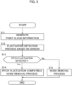
- FIG. 5 is an example of a flowchart illustrating a procedure of the point cloud information process according to the second embodiment.
- the lidar 100A repeatedly executes the point cloud information process at each cycle of generating a frame of point cloud information.
- the point cloud information generation block 72 generates point cloud information based on the detection signal Sg2 (step S 11).
- the point cloud information processing block 73 executes the fluctuation detection process based on the detection signal Sg5 outputted by the sensor 9 (step S 12).
- the point cloud information processing block 73 accurately detects the fluctuation when the lidar 100 fluctuates in the pitch direction due to the passage of the vehicle through bumps or steps or the like.
- the point cloud information processing block 73 Upon detecting the fluctuation in the pitch direction through the fluctuation detection process (step S13;Yes), the point cloud information processing block 73 executes the pitch fluctuation compatible noise removal process that is the removal process of the noise data based on the past frame and the current frame on the assumption that there is a fluctuation in the pitch direction (step S14). In this case, the point cloud information processing block 73 sets the existing fluctuation search range with respect to each valid point in the past frame, and searches for any measured point in the current frame which satisfies the condition that the difference in the measurement distance is equal to or smaller than a predetermined distance.
- the point cloud information processing block 73 sets, as a valid point, a measured point in the current frame having similar measurement distance to a predetermined or more of measured points in the past frame while setting any other measured point as an invalid point. Further, the point cloud information processing block 73 also performs the process of setting, as an invalid point, any measured point for which the intensity of the reflected light received by the receiving unit 2 is less than a predetermined threshold value, and the process of setting, as an invalid point, any measured point which belongs to a cluster, generated through clustering of measured points, in which the number of elements is equal to or smaller than a predetermined threshold value.
- the point cloud information processing block 73 executes the normal noise removal process (step S15). In this instance, the point cloud information processing block 73 executes the same noise removal process as the process at step S02 according to the first embodiment.
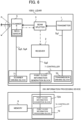
- FIG. 6 is a configuration diagram of a lidar system according to the third embodiment.
- a device separate from the lidar 100X is equipped with the function corresponding to the point cloud information processing block 73 of the controller 7.
- the same components in the third embodiment as in the first embodiment or the second embodiment are appropriately denoted by the same reference numerals as in the first embodiment or the second embodiment, and a description thereof will be omitted.
- the lidar system according to the third embodiment includes a lidar 100X and an information processing device 200.
- the lidar 100X supplies the point cloud information generated by the point cloud information generation block 72 to the information processing device 200.
- the information processing device 200 includes a controller 7A and a memory 8.
- the memory 8 stores the data required for the controller 7A to execute the process.
- the controller 7A functionally includes a point cloud information acquisition block 72A and a point cloud information processing block 73.
- the point cloud information acquisition block 72A receives the point cloud information generated by the point cloud information generation block 72 of the lidar 100X, and supplies the received point cloud information to the point cloud information processing block 73.
- the point cloud information processing block 73 performs the same process as the process, which is executed by the point cloud information processing block 73 according to the above-described embodiments on the point cloud information supplied from the point cloud information acquisition block 72A.
- the information processing device 200 may be realized by a driving support device.
- the parameter information necessary for processing may be stored by another device having a memory that can be referenced by the information processing device 200.
- the configuration according to this modification also enables the information processing device 200 to accurately execute the noise removal of the point cloud information generated by the lidar 100X.
- the controller 7 of the lidar 100 according to the first embodiment or the second embodiment or the controller 7A of the information processing device 200 according to the third embodiment functions as the information processing device according to the present invention, and functionally includes an acquisition means, a detection means, and a processing means.
- the acquisition means is configured to acquire point cloud information which is a set of data representing a point measured by a measurement device for each measurement direction.
- the detection means is configured to detect a predetermined degree of fluctuation in the measurement device.
- the processing means is configured to determine, based on whether the fluctuation is detected or not, a search range for searching for a corresponding point of the point cloud information obtained at the preceding processing time, wherein the corresponding point corresponds to each point of the point cloud information obtained at the current processing time.
- the program is stored by any type of a non-transitory computer-readable medium (non-transitory computer readable medium) and can be supplied to a control unit or the like that is a computer.
- the non-transitory computer-readable medium include any type of a tangible storage medium.
- non-transitory computer readable medium examples include a magnetic storage medium (e.g., a flexible disk, a magnetic tape, a hard disk drive), a magnetic-optical storage medium (e.g., a magnetic optical disk), CD-ROM (Read Only Memory), CD-R, CD-R/W, a solid-state memory (e.g., a mask ROM, a PROM (Programmable ROM), an EPROM (Erasable PROM), a flash ROM, a RAM (Random Access Memory)).
- a magnetic storage medium e.g., a flexible disk, a magnetic tape, a hard disk drive
- a magnetic-optical storage medium e.g., a magnetic optical disk
- CD-ROM Read Only Memory
- CD-R Compact Only Memory
- CD-R/W examples of the non-transitory computer readable medium
- solid-state memory e.g., a mask ROM, a PROM (Programmable ROM), an EPROM (Erasable
Landscapes
- Engineering & Computer Science (AREA)
- Physics & Mathematics (AREA)
- Radar, Positioning & Navigation (AREA)
- Remote Sensing (AREA)
- Computer Networks & Wireless Communication (AREA)
- General Physics & Mathematics (AREA)
- Electromagnetism (AREA)
- Optical Radar Systems And Details Thereof (AREA)
Applications Claiming Priority (1)
| Application Number | Priority Date | Filing Date | Title |
|---|---|---|---|
| PCT/JP2022/005352 WO2023152870A1 (ja) | 2022-02-10 | 2022-02-10 | 情報処理装置、制御方法、プログラム及び記憶媒体 |
Publications (2)
| Publication Number | Publication Date |
|---|---|
| EP4478086A1 true EP4478086A1 (de) | 2024-12-18 |
| EP4478086A4 EP4478086A4 (de) | 2025-11-26 |
Family
ID=87563953
Family Applications (1)
| Application Number | Title | Priority Date | Filing Date |
|---|---|---|---|
| EP22925891.8A Pending EP4478086A4 (de) | 2022-02-10 | 2022-02-10 | Informationsverarbeitungsvorrichtung, steuerungsverfahren, programm und speichermedium |
Country Status (5)
| Country | Link |
|---|---|
| US (1) | US20250110240A1 (de) |
| EP (1) | EP4478086A4 (de) |
| JP (2) | JP7717199B2 (de) |
| CN (1) | CN118696246A (de) |
| WO (1) | WO2023152870A1 (de) |
Family Cites Families (8)
| Publication number | Priority date | Publication date | Assignee | Title |
|---|---|---|---|---|
| JP2008082750A (ja) | 2006-09-26 | 2008-04-10 | Toyota Motor Corp | 前方車両認識装置 |
| DE102011054852B4 (de) | 2011-07-30 | 2024-05-16 | Götting KG | Verfahren zur Erfassung und Bewertung einer Ebene |
| JP6354556B2 (ja) * | 2014-12-10 | 2018-07-11 | 株式会社デンソー | 位置推定装置、位置推定方法、位置推定プログラム |
| CN106530380B (zh) * | 2016-09-20 | 2019-02-26 | 长安大学 | 一种基于三维激光雷达的地面点云分割方法 |
| US10254762B2 (en) | 2017-03-29 | 2019-04-09 | Luminar Technologies, Inc. | Compensating for the vibration of the vehicle |
| US11300958B2 (en) | 2017-07-13 | 2022-04-12 | Waymo Llc | Sensor adjustment based on vehicle motion |
| JP7206127B2 (ja) * | 2019-02-20 | 2023-01-17 | 株式会社Ihiエアロスペース | 画像センサの情報補正方法及び移動体 |
| JP7477139B2 (ja) * | 2020-02-19 | 2024-05-01 | 北陽電機株式会社 | 物体検出装置、物体検出システム、物体検出プログラムおよび物体検出方法 |
-
2022
- 2022-02-10 CN CN202280090616.5A patent/CN118696246A/zh active Pending
- 2022-02-10 EP EP22925891.8A patent/EP4478086A4/de active Pending
- 2022-02-10 JP JP2023579952A patent/JP7717199B2/ja active Active
- 2022-02-10 US US18/835,981 patent/US20250110240A1/en active Pending
- 2022-02-10 WO PCT/JP2022/005352 patent/WO2023152870A1/ja not_active Ceased
-
2025
- 2025-07-22 JP JP2025122416A patent/JP2025157476A/ja active Pending
Also Published As
| Publication number | Publication date |
|---|---|
| EP4478086A4 (de) | 2025-11-26 |
| JP7717199B2 (ja) | 2025-08-01 |
| WO2023152870A1 (ja) | 2023-08-17 |
| JPWO2023152870A1 (de) | 2023-08-17 |
| CN118696246A (zh) | 2024-09-24 |
| US20250110240A1 (en) | 2025-04-03 |
| JP2025157476A (ja) | 2025-10-15 |
Similar Documents
| Publication | Publication Date | Title |
|---|---|---|
| US11961306B2 (en) | Object detection device | |
| US8810445B2 (en) | Method and apparatus for recognizing presence of objects | |
| US10908257B2 (en) | Signal processing apparatus, signal processing method, and program | |
| JP5267592B2 (ja) | 物体認識装置 | |
| JP7214888B2 (ja) | レーダ電力制御方法および装置 | |
| WO2019082700A1 (ja) | 制御装置、制御方法、プログラム及び記憶媒体 | |
| JP2016133341A (ja) | 物体検出装置、センシング装置、移動体装置及び物体検出方法 | |
| JP6645254B2 (ja) | 物体認識装置 | |
| CN114730014B (zh) | 物体识别装置和物体识别方法 | |
| US20230065210A1 (en) | Optical distance measuring device | |
| JP7763369B2 (ja) | 情報処理装置、情報処理方法、プログラム及び記憶媒体 | |
| JP2022139739A (ja) | 情報処理装置、情報処理方法、プログラム及び記憶媒体 | |
| EP3767326B1 (de) | Sensorsteuerungsvorrichtung | |
| JP2004184331A (ja) | 車両用物体認識装置 | |
| US20220404499A1 (en) | Distance measurement apparatus | |
| JP5556317B2 (ja) | 物体認識装置 | |
| EP4478086A1 (de) | Informationsverarbeitungsvorrichtung, steuerungsverfahren, programm und speichermedium | |
| EP4478331A1 (de) | Informationsverarbeitungsvorrichtung, steuerungsverfahren, programm und speichermedium | |
| JP2023064482A (ja) | 情報処理装置、制御方法、プログラム及び記憶媒体 | |
| JP6390459B2 (ja) | 光軸ずれ検出装置 | |
| US20230311897A1 (en) | Automotive sensing system and gating camera | |
| JP2022135351A (ja) | 情報処理装置、情報処理方法、プログラム及び記憶媒体 | |
| JP7607425B2 (ja) | 情報処理装置、制御方法、プログラム及び記憶媒体 | |
| WO2022186103A1 (ja) | 情報処理装置、情報処理方法、プログラム及び記憶媒体 | |
| US20240410996A1 (en) | Ranging device and ranging method |
Legal Events
| Date | Code | Title | Description |
|---|---|---|---|
| STAA | Information on the status of an ep patent application or granted ep patent |
Free format text: STATUS: THE INTERNATIONAL PUBLICATION HAS BEEN MADE |
|
| PUAI | Public reference made under article 153(3) epc to a published international application that has entered the european phase |
Free format text: ORIGINAL CODE: 0009012 |
|
| STAA | Information on the status of an ep patent application or granted ep patent |
Free format text: STATUS: REQUEST FOR EXAMINATION WAS MADE |
|
| 17P | Request for examination filed |
Effective date: 20240729 |
|
| AK | Designated contracting states |
Kind code of ref document: A1 Designated state(s): AL AT BE BG CH CY CZ DE DK EE ES FI FR GB GR HR HU IE IS IT LI LT LU LV MC MK MT NL NO PL PT RO RS SE SI SK SM TR |
|
| DAV | Request for validation of the european patent (deleted) | ||
| DAX | Request for extension of the european patent (deleted) | ||
| REG | Reference to a national code |
Ref country code: DE Ref legal event code: R079 Free format text: PREVIOUS MAIN CLASS: G01S0007497000 Ipc: G01S0007480000 |
|
| A4 | Supplementary search report drawn up and despatched |
Effective date: 20251029 |
|
| RIC1 | Information provided on ipc code assigned before grant |
Ipc: G01S 7/48 20060101AFI20251023BHEP Ipc: G01S 7/481 20060101ALI20251023BHEP Ipc: G01S 7/497 20060101ALI20251023BHEP Ipc: G01S 17/10 20200101ALI20251023BHEP Ipc: G01S 17/42 20060101ALI20251023BHEP Ipc: G01S 17/86 20200101ALI20251023BHEP Ipc: G01S 17/89 20200101ALI20251023BHEP Ipc: G01S 17/931 20200101ALI20251023BHEP |