EP4477940A1 - Procédé de fonctionnement de réservoirs de gaz - Google Patents
Procédé de fonctionnement de réservoirs de gaz Download PDFInfo
- Publication number
- EP4477940A1 EP4477940A1 EP23179742.4A EP23179742A EP4477940A1 EP 4477940 A1 EP4477940 A1 EP 4477940A1 EP 23179742 A EP23179742 A EP 23179742A EP 4477940 A1 EP4477940 A1 EP 4477940A1
- Authority
- EP
- European Patent Office
- Prior art keywords
- pressure vessel
- fuel
- temperature
- pressure
- volume
- Prior art date
- Legal status (The legal status is an assumption and is not a legal conclusion. Google has not performed a legal analysis and makes no representation as to the accuracy of the status listed.)
- Granted
Links
Images

Classifications
-
- F—MECHANICAL ENGINEERING; LIGHTING; HEATING; WEAPONS; BLASTING
- F17—STORING OR DISTRIBUTING GASES OR LIQUIDS
- F17C—VESSELS FOR CONTAINING OR STORING COMPRESSED, LIQUEFIED OR SOLIDIFIED GASES; FIXED-CAPACITY GAS-HOLDERS; FILLING VESSELS WITH, OR DISCHARGING FROM VESSELS, COMPRESSED, LIQUEFIED, OR SOLIDIFIED GASES
- F17C5/00—Methods or apparatus for filling containers with liquefied, solidified, or compressed gases under pressures
- F17C5/002—Automated filling apparatus
- F17C5/007—Automated filling apparatus for individual gas tanks or containers, e.g. in vehicles
-
- F—MECHANICAL ENGINEERING; LIGHTING; HEATING; WEAPONS; BLASTING
- F17—STORING OR DISTRIBUTING GASES OR LIQUIDS
- F17C—VESSELS FOR CONTAINING OR STORING COMPRESSED, LIQUEFIED OR SOLIDIFIED GASES; FIXED-CAPACITY GAS-HOLDERS; FILLING VESSELS WITH, OR DISCHARGING FROM VESSELS, COMPRESSED, LIQUEFIED, OR SOLIDIFIED GASES
- F17C13/00—Details of vessels or of the filling or discharging of vessels
- F17C13/02—Special adaptations of indicating, measuring, or monitoring equipment
- F17C13/026—Special adaptations of indicating, measuring, or monitoring equipment having the temperature as the parameter
-
- F—MECHANICAL ENGINEERING; LIGHTING; HEATING; WEAPONS; BLASTING
- F17—STORING OR DISTRIBUTING GASES OR LIQUIDS
- F17C—VESSELS FOR CONTAINING OR STORING COMPRESSED, LIQUEFIED OR SOLIDIFIED GASES; FIXED-CAPACITY GAS-HOLDERS; FILLING VESSELS WITH, OR DISCHARGING FROM VESSELS, COMPRESSED, LIQUEFIED, OR SOLIDIFIED GASES
- F17C13/00—Details of vessels or of the filling or discharging of vessels
- F17C13/04—Arrangement or mounting of valves
-
- F—MECHANICAL ENGINEERING; LIGHTING; HEATING; WEAPONS; BLASTING
- F17—STORING OR DISTRIBUTING GASES OR LIQUIDS
- F17C—VESSELS FOR CONTAINING OR STORING COMPRESSED, LIQUEFIED OR SOLIDIFIED GASES; FIXED-CAPACITY GAS-HOLDERS; FILLING VESSELS WITH, OR DISCHARGING FROM VESSELS, COMPRESSED, LIQUEFIED, OR SOLIDIFIED GASES
- F17C5/00—Methods or apparatus for filling containers with liquefied, solidified, or compressed gases under pressures
-
- F—MECHANICAL ENGINEERING; LIGHTING; HEATING; WEAPONS; BLASTING
- F17—STORING OR DISTRIBUTING GASES OR LIQUIDS
- F17C—VESSELS FOR CONTAINING OR STORING COMPRESSED, LIQUEFIED OR SOLIDIFIED GASES; FIXED-CAPACITY GAS-HOLDERS; FILLING VESSELS WITH, OR DISCHARGING FROM VESSELS, COMPRESSED, LIQUEFIED, OR SOLIDIFIED GASES
- F17C7/00—Methods or apparatus for discharging liquefied, solidified, or compressed gases from pressure vessels, not covered by another subclass
-
- F—MECHANICAL ENGINEERING; LIGHTING; HEATING; WEAPONS; BLASTING
- F17—STORING OR DISTRIBUTING GASES OR LIQUIDS
- F17C—VESSELS FOR CONTAINING OR STORING COMPRESSED, LIQUEFIED OR SOLIDIFIED GASES; FIXED-CAPACITY GAS-HOLDERS; FILLING VESSELS WITH, OR DISCHARGING FROM VESSELS, COMPRESSED, LIQUEFIED, OR SOLIDIFIED GASES
- F17C2201/00—Vessel construction, in particular geometry, arrangement or size
- F17C2201/01—Shape
- F17C2201/0104—Shape cylindrical
- F17C2201/0109—Shape cylindrical with exteriorly curved end-piece
-
- F—MECHANICAL ENGINEERING; LIGHTING; HEATING; WEAPONS; BLASTING
- F17—STORING OR DISTRIBUTING GASES OR LIQUIDS
- F17C—VESSELS FOR CONTAINING OR STORING COMPRESSED, LIQUEFIED OR SOLIDIFIED GASES; FIXED-CAPACITY GAS-HOLDERS; FILLING VESSELS WITH, OR DISCHARGING FROM VESSELS, COMPRESSED, LIQUEFIED, OR SOLIDIFIED GASES
- F17C2205/00—Vessel construction, in particular mounting arrangements, attachments or identifications means
- F17C2205/01—Mounting arrangements
- F17C2205/0123—Mounting arrangements characterised by number of vessels
- F17C2205/013—Two or more vessels
- F17C2205/0134—Two or more vessels characterised by the presence of fluid connection between vessels
- F17C2205/0138—Two or more vessels characterised by the presence of fluid connection between vessels bundled in series
-
- F—MECHANICAL ENGINEERING; LIGHTING; HEATING; WEAPONS; BLASTING
- F17—STORING OR DISTRIBUTING GASES OR LIQUIDS
- F17C—VESSELS FOR CONTAINING OR STORING COMPRESSED, LIQUEFIED OR SOLIDIFIED GASES; FIXED-CAPACITY GAS-HOLDERS; FILLING VESSELS WITH, OR DISCHARGING FROM VESSELS, COMPRESSED, LIQUEFIED, OR SOLIDIFIED GASES
- F17C2205/00—Vessel construction, in particular mounting arrangements, attachments or identifications means
- F17C2205/03—Fluid connections, filters, valves, closure means or other attachments
- F17C2205/0302—Fittings, valves, filters, or components in connection with the gas storage device
- F17C2205/0323—Valves
-
- F—MECHANICAL ENGINEERING; LIGHTING; HEATING; WEAPONS; BLASTING
- F17—STORING OR DISTRIBUTING GASES OR LIQUIDS
- F17C—VESSELS FOR CONTAINING OR STORING COMPRESSED, LIQUEFIED OR SOLIDIFIED GASES; FIXED-CAPACITY GAS-HOLDERS; FILLING VESSELS WITH, OR DISCHARGING FROM VESSELS, COMPRESSED, LIQUEFIED, OR SOLIDIFIED GASES
- F17C2205/00—Vessel construction, in particular mounting arrangements, attachments or identifications means
- F17C2205/03—Fluid connections, filters, valves, closure means or other attachments
- F17C2205/0302—Fittings, valves, filters, or components in connection with the gas storage device
- F17C2205/0323—Valves
- F17C2205/0326—Valves electrically actuated
-
- F—MECHANICAL ENGINEERING; LIGHTING; HEATING; WEAPONS; BLASTING
- F17—STORING OR DISTRIBUTING GASES OR LIQUIDS
- F17C—VESSELS FOR CONTAINING OR STORING COMPRESSED, LIQUEFIED OR SOLIDIFIED GASES; FIXED-CAPACITY GAS-HOLDERS; FILLING VESSELS WITH, OR DISCHARGING FROM VESSELS, COMPRESSED, LIQUEFIED, OR SOLIDIFIED GASES
- F17C2221/00—Handled fluid, in particular type of fluid
- F17C2221/01—Pure fluids
- F17C2221/012—Hydrogen
-
- F—MECHANICAL ENGINEERING; LIGHTING; HEATING; WEAPONS; BLASTING
- F17—STORING OR DISTRIBUTING GASES OR LIQUIDS
- F17C—VESSELS FOR CONTAINING OR STORING COMPRESSED, LIQUEFIED OR SOLIDIFIED GASES; FIXED-CAPACITY GAS-HOLDERS; FILLING VESSELS WITH, OR DISCHARGING FROM VESSELS, COMPRESSED, LIQUEFIED, OR SOLIDIFIED GASES
- F17C2221/00—Handled fluid, in particular type of fluid
- F17C2221/03—Mixtures
- F17C2221/032—Hydrocarbons
- F17C2221/033—Methane, e.g. natural gas, CNG, LNG, GNL, GNC, PLNG
-
- F—MECHANICAL ENGINEERING; LIGHTING; HEATING; WEAPONS; BLASTING
- F17—STORING OR DISTRIBUTING GASES OR LIQUIDS
- F17C—VESSELS FOR CONTAINING OR STORING COMPRESSED, LIQUEFIED OR SOLIDIFIED GASES; FIXED-CAPACITY GAS-HOLDERS; FILLING VESSELS WITH, OR DISCHARGING FROM VESSELS, COMPRESSED, LIQUEFIED, OR SOLIDIFIED GASES
- F17C2221/00—Handled fluid, in particular type of fluid
- F17C2221/03—Mixtures
- F17C2221/032—Hydrocarbons
- F17C2221/035—Propane butane, e.g. LPG, GPL
-
- F—MECHANICAL ENGINEERING; LIGHTING; HEATING; WEAPONS; BLASTING
- F17—STORING OR DISTRIBUTING GASES OR LIQUIDS
- F17C—VESSELS FOR CONTAINING OR STORING COMPRESSED, LIQUEFIED OR SOLIDIFIED GASES; FIXED-CAPACITY GAS-HOLDERS; FILLING VESSELS WITH, OR DISCHARGING FROM VESSELS, COMPRESSED, LIQUEFIED, OR SOLIDIFIED GASES
- F17C2223/00—Handled fluid before transfer, i.e. state of fluid when stored in the vessel or before transfer from the vessel
- F17C2223/01—Handled fluid before transfer, i.e. state of fluid when stored in the vessel or before transfer from the vessel characterised by the phase
- F17C2223/0107—Single phase
- F17C2223/0123—Single phase gaseous, e.g. CNG, GNC
-
- F—MECHANICAL ENGINEERING; LIGHTING; HEATING; WEAPONS; BLASTING
- F17—STORING OR DISTRIBUTING GASES OR LIQUIDS
- F17C—VESSELS FOR CONTAINING OR STORING COMPRESSED, LIQUEFIED OR SOLIDIFIED GASES; FIXED-CAPACITY GAS-HOLDERS; FILLING VESSELS WITH, OR DISCHARGING FROM VESSELS, COMPRESSED, LIQUEFIED, OR SOLIDIFIED GASES
- F17C2223/00—Handled fluid before transfer, i.e. state of fluid when stored in the vessel or before transfer from the vessel
- F17C2223/03—Handled fluid before transfer, i.e. state of fluid when stored in the vessel or before transfer from the vessel characterised by the pressure level
- F17C2223/036—Very high pressure (>80 bar)
-
- F—MECHANICAL ENGINEERING; LIGHTING; HEATING; WEAPONS; BLASTING
- F17—STORING OR DISTRIBUTING GASES OR LIQUIDS
- F17C—VESSELS FOR CONTAINING OR STORING COMPRESSED, LIQUEFIED OR SOLIDIFIED GASES; FIXED-CAPACITY GAS-HOLDERS; FILLING VESSELS WITH, OR DISCHARGING FROM VESSELS, COMPRESSED, LIQUEFIED, OR SOLIDIFIED GASES
- F17C2227/00—Transfer of fluids, i.e. method or means for transferring the fluid; Heat exchange with the fluid
- F17C2227/03—Heat exchange with the fluid
- F17C2227/0302—Heat exchange with the fluid by heating
- F17C2227/0325—Heat exchange with the fluid by heating by expansion using "Joule-Thompson" effect
-
- F—MECHANICAL ENGINEERING; LIGHTING; HEATING; WEAPONS; BLASTING
- F17—STORING OR DISTRIBUTING GASES OR LIQUIDS
- F17C—VESSELS FOR CONTAINING OR STORING COMPRESSED, LIQUEFIED OR SOLIDIFIED GASES; FIXED-CAPACITY GAS-HOLDERS; FILLING VESSELS WITH, OR DISCHARGING FROM VESSELS, COMPRESSED, LIQUEFIED, OR SOLIDIFIED GASES
- F17C2227/00—Transfer of fluids, i.e. method or means for transferring the fluid; Heat exchange with the fluid
- F17C2227/04—Methods for emptying or filling
-
- F—MECHANICAL ENGINEERING; LIGHTING; HEATING; WEAPONS; BLASTING
- F17—STORING OR DISTRIBUTING GASES OR LIQUIDS
- F17C—VESSELS FOR CONTAINING OR STORING COMPRESSED, LIQUEFIED OR SOLIDIFIED GASES; FIXED-CAPACITY GAS-HOLDERS; FILLING VESSELS WITH, OR DISCHARGING FROM VESSELS, COMPRESSED, LIQUEFIED, OR SOLIDIFIED GASES
- F17C2250/00—Accessories; Control means; Indicating, measuring or monitoring of parameters
- F17C2250/03—Control means
-
- F—MECHANICAL ENGINEERING; LIGHTING; HEATING; WEAPONS; BLASTING
- F17—STORING OR DISTRIBUTING GASES OR LIQUIDS
- F17C—VESSELS FOR CONTAINING OR STORING COMPRESSED, LIQUEFIED OR SOLIDIFIED GASES; FIXED-CAPACITY GAS-HOLDERS; FILLING VESSELS WITH, OR DISCHARGING FROM VESSELS, COMPRESSED, LIQUEFIED, OR SOLIDIFIED GASES
- F17C2250/00—Accessories; Control means; Indicating, measuring or monitoring of parameters
- F17C2250/04—Indicating or measuring of parameters as input values
- F17C2250/0404—Parameters indicated or measured
- F17C2250/043—Pressure
-
- F—MECHANICAL ENGINEERING; LIGHTING; HEATING; WEAPONS; BLASTING
- F17—STORING OR DISTRIBUTING GASES OR LIQUIDS
- F17C—VESSELS FOR CONTAINING OR STORING COMPRESSED, LIQUEFIED OR SOLIDIFIED GASES; FIXED-CAPACITY GAS-HOLDERS; FILLING VESSELS WITH, OR DISCHARGING FROM VESSELS, COMPRESSED, LIQUEFIED, OR SOLIDIFIED GASES
- F17C2250/00—Accessories; Control means; Indicating, measuring or monitoring of parameters
- F17C2250/04—Indicating or measuring of parameters as input values
- F17C2250/0404—Parameters indicated or measured
- F17C2250/0439—Temperature
-
- F—MECHANICAL ENGINEERING; LIGHTING; HEATING; WEAPONS; BLASTING
- F17—STORING OR DISTRIBUTING GASES OR LIQUIDS
- F17C—VESSELS FOR CONTAINING OR STORING COMPRESSED, LIQUEFIED OR SOLIDIFIED GASES; FIXED-CAPACITY GAS-HOLDERS; FILLING VESSELS WITH, OR DISCHARGING FROM VESSELS, COMPRESSED, LIQUEFIED, OR SOLIDIFIED GASES
- F17C2250/00—Accessories; Control means; Indicating, measuring or monitoring of parameters
- F17C2250/06—Controlling or regulating of parameters as output values
- F17C2250/0605—Parameters
- F17C2250/0631—Temperature
-
- F—MECHANICAL ENGINEERING; LIGHTING; HEATING; WEAPONS; BLASTING
- F17—STORING OR DISTRIBUTING GASES OR LIQUIDS
- F17C—VESSELS FOR CONTAINING OR STORING COMPRESSED, LIQUEFIED OR SOLIDIFIED GASES; FIXED-CAPACITY GAS-HOLDERS; FILLING VESSELS WITH, OR DISCHARGING FROM VESSELS, COMPRESSED, LIQUEFIED, OR SOLIDIFIED GASES
- F17C2260/00—Purposes of gas storage and gas handling
- F17C2260/02—Improving properties related to fluid or fluid transfer
- F17C2260/023—Avoiding overheating
-
- F—MECHANICAL ENGINEERING; LIGHTING; HEATING; WEAPONS; BLASTING
- F17—STORING OR DISTRIBUTING GASES OR LIQUIDS
- F17C—VESSELS FOR CONTAINING OR STORING COMPRESSED, LIQUEFIED OR SOLIDIFIED GASES; FIXED-CAPACITY GAS-HOLDERS; FILLING VESSELS WITH, OR DISCHARGING FROM VESSELS, COMPRESSED, LIQUEFIED, OR SOLIDIFIED GASES
- F17C2265/00—Effects achieved by gas storage or gas handling
- F17C2265/06—Fluid distribution
- F17C2265/065—Fluid distribution for refuelling vehicle fuel tanks
-
- F—MECHANICAL ENGINEERING; LIGHTING; HEATING; WEAPONS; BLASTING
- F17—STORING OR DISTRIBUTING GASES OR LIQUIDS
- F17C—VESSELS FOR CONTAINING OR STORING COMPRESSED, LIQUEFIED OR SOLIDIFIED GASES; FIXED-CAPACITY GAS-HOLDERS; FILLING VESSELS WITH, OR DISCHARGING FROM VESSELS, COMPRESSED, LIQUEFIED, OR SOLIDIFIED GASES
- F17C2270/00—Applications
- F17C2270/01—Applications for fluid transport or storage
- F17C2270/0165—Applications for fluid transport or storage on the road
- F17C2270/0168—Applications for fluid transport or storage on the road by vehicles
-
- F—MECHANICAL ENGINEERING; LIGHTING; HEATING; WEAPONS; BLASTING
- F17—STORING OR DISTRIBUTING GASES OR LIQUIDS
- F17C—VESSELS FOR CONTAINING OR STORING COMPRESSED, LIQUEFIED OR SOLIDIFIED GASES; FIXED-CAPACITY GAS-HOLDERS; FILLING VESSELS WITH, OR DISCHARGING FROM VESSELS, COMPRESSED, LIQUEFIED, OR SOLIDIFIED GASES
- F17C2270/00—Applications
- F17C2270/01—Applications for fluid transport or storage
- F17C2270/0165—Applications for fluid transport or storage on the road
- F17C2270/0168—Applications for fluid transport or storage on the road by vehicles
- F17C2270/0178—Cars
-
- F—MECHANICAL ENGINEERING; LIGHTING; HEATING; WEAPONS; BLASTING
- F17—STORING OR DISTRIBUTING GASES OR LIQUIDS
- F17C—VESSELS FOR CONTAINING OR STORING COMPRESSED, LIQUEFIED OR SOLIDIFIED GASES; FIXED-CAPACITY GAS-HOLDERS; FILLING VESSELS WITH, OR DISCHARGING FROM VESSELS, COMPRESSED, LIQUEFIED, OR SOLIDIFIED GASES
- F17C2270/00—Applications
- F17C2270/01—Applications for fluid transport or storage
- F17C2270/0165—Applications for fluid transport or storage on the road
- F17C2270/0184—Fuel cells
-
- Y—GENERAL TAGGING OF NEW TECHNOLOGICAL DEVELOPMENTS; GENERAL TAGGING OF CROSS-SECTIONAL TECHNOLOGIES SPANNING OVER SEVERAL SECTIONS OF THE IPC; TECHNICAL SUBJECTS COVERED BY FORMER USPC CROSS-REFERENCE ART COLLECTIONS [XRACs] AND DIGESTS
- Y02—TECHNOLOGIES OR APPLICATIONS FOR MITIGATION OR ADAPTATION AGAINST CLIMATE CHANGE
- Y02E—REDUCTION OF GREENHOUSE GAS [GHG] EMISSIONS, RELATED TO ENERGY GENERATION, TRANSMISSION OR DISTRIBUTION
- Y02E60/00—Enabling technologies; Technologies with a potential or indirect contribution to GHG emissions mitigation
- Y02E60/30—Hydrogen technology
- Y02E60/32—Hydrogen storage
Definitions
- the invention relates to a method for operating gas storage facilities.
- the invention relates to a method for filling gas storage facilities and removing gas from gas storage facilities, in particular for filling gas storage facilities and removing gas from gas storage facilities for use in a vehicle, the gas serving as fuel for operating the vehicle.
- the invention further relates to a system of gas storage facilities for carrying out the method.
- Cylindrical pressure vessels currently in use have a reinforcement layer made of fiber composite material made of fibers embedded in a matrix material, which is wound as an outer layer using a winding process onto an inner container (the so-called liner) of the pressure vessel, which acts as the winding core. While the inner container, for example, guarantees the gas-tightness of the pressure vessel, the reinforcement layer made of fiber composite material gives the pressure vessel the necessary mechanical stability.
- Type 3 pressure vessels use a mechanical inner container (metallic liner), e.g. made of aluminum or steel, while type 4 pressure vessels have an inner container (liner) made of plastic.
- pressure vessels are also known that consist of only one or more metallic materials.
- Pressure vessels are filled with filling gas. Since very high pressures and low temperatures prevail, especially at hydrogen filling stations, and hydrogen is highly explosive in combination with oxygen, high demands must be placed on these. Furthermore, safety must be guaranteed at filling stations when filling vehicles and filling various containers one after the other.
- the SAE TIR J 2601 guideline describes the refueling procedure for hydrogen-powered vehicles. According to this, the communication capability of the vehicle to be filled or its hydrogen tank is first determined.
- the hydrogen tank does not have to consist of a single tank. On the contrary, it is common for the hydrogen tank to consist of a system of individual tanks that are effectively connected to one another.
- the system usually has a check valve, although it is also common for each tank in a system to have a check valve if there are several individual tanks.
- the hydrogen filling station then carries out a pressure surge.
- This pressure surge opens all check valves so that pressure can be exchanged between the vehicle and the filling station.
- This pressure surge corresponds to the pressure query for non-electronically communicating motor vehicles.
- the pressure exchange sets the starting pressure for refueling the respective vehicle.
- a leak test of the system is then carried out to ensure safety.
- the filling procedure then begins, the parameters of which, in particular the filling pressure, are selected in a ramp-like manner depending on the starting pressure.
- the average pressure increase rate method is usually used, which determines a pressure increase rate (max. approx. 60 g hydrogen/s) depending on the starting temperature and the starting pressure, so that the filling time depends on the tank size.
- the maximum operating pressure can be between 200 and 1200 bar, typically between 350 and 875 bar, depending on the application.
- a fuel cell or a Internal combustion engine can be supplied with hydrogen. During filling, the gas flowing into the pressure vessel or pressure vessel system heats up due to compression. If a fuel cell or internal combustion engine is to be put into operation after a pressure vessel or pressure vessel system has been filled, and the hydrogen is to be taken from this pressure vessel or pressure vessel system, the tank pressure must be throttled down to the pressure of the fuel cell or internal combustion engine. In the case of a fuel cell, this pressure is typically between 8 and 12 bar, and in the case of an internal combustion engine, it is around 30 bar. The pressure reduction is usually achieved with a pressure reducer.
- the temperature of hydrogen increases depending on the pressure difference between high pressure and low pressure. This temperature increase can be in the range of up to 40 K. If the temperature after the pressure reducer exceeds the permissible limits of the valves or the fuel cell, operation must be interrupted until the gas has cooled down sufficiently.
- the permissible upper limit temperature of a fuel cell i.e. the maximum inlet temperature of the fuel gas, is typically around 85 °C. The filling gas does cool down when it is removed, for example to feed it to a fuel cell.
- Cooling devices are therefore usually provided to cool the filling gas after filling to a temperature below the limit temperature.
- a minimum gas inlet temperature in the fuel cell is usually defined, which the storage system must maintain. This is, for example, - 40°C. If the inlet temperature is too low, the fuel cell must be switched off until the gas inlet temperature has reached the permitted range. In this case, too, undesirable waiting times arise.
- the gas inlet temperature is as close as possible to or even above the limit temperature in order to minimize the energy requirement of the fuel cell to temper the gas to operating temperature.
- a further disadvantage of temperature control of the fuel cell and/or filling gas is that this temperature control itself is complex and consumes energy during operation.
- the present invention is based on the object of providing an improvement or an alternative to the prior art.
- the stated object is achieved by a method for removing a fuel from a pressure vessel system with a first pressure vessel with a first volume and a second pressure vessel with a second volume, wherein the first volume is smaller than the second volume, and wherein either the fuel is first at least partially removed from the first pressure vessel before the fuel is removed exclusively from the second pressure vessel, provided that the fuel in the second pressure vessel has a temperature outside a previously defined permissible temperature window, or the fuel is first at least partially removed from the second pressure vessel before the fuel is removed exclusively from the first pressure vessel, provided that the fuel in the second pressure vessel has a temperature within a previously defined temperature window, wherein the fuel removal from the second pressure vessel is stopped and switched to the first pressure vessel as soon as the temperature of the fuel from the second pressure vessel leaves the previously defined temperature window.
- This also makes it possible for the fuel to be first removed from both pressure vessels before the fuel is removed exclusively from the first or second pressure vessel.
- the terms "fuel”, “filling gas”, “gas”, “fuel”, etc. are used synonymously in this document.
- the invention can generally be used for the removal of gaseous substances from a pressure vessel system. However, the invention can be used particularly advantageously when using hydrogen as fuel for operating a fuel cell or for combustion in a corresponding internal combustion engine to drive a vehicle.
- a "pressure vessel system” is understood to mean a plurality of pressure vessels that are operatively connected to one another.
- hydrogen-powered vehicles usually have pressure vessel systems, whereby the operatively connected pressure vessels can have different volumes.
- Pressure vessels for hydrogen must withstand high internal pressures of up to 1,200 bar and therefore usually have a spherical shape or a cylindrical middle section, whereby the cylindrical middle section is closed by pole caps.
- several pressure vessels are usually combined in vehicles to form a pressure vessel system, whereby the individual pressure vessels can have different volumes and can usually be filled via a common filling line.
- the hydrogen is removed via a removal valve, whereby each pressure vessel usually has a separate removal valve.
- vehicle in this document refers to any vehicle, such as a motor vehicle, in particular a passenger vehicle, or a commercial vehicle, such as a truck, van, bus or agricultural vehicle, or a rail-bound vehicle, as well as a watercraft, aircraft or spacecraft.
- vehicle also includes appropriately powered work machines.
- the filling process is also called "refueling", especially in vehicles.
- a “pressure reducer” is a pressure valve for installation in a hose or pipe system that ensures that a certain output pressure is not exceeded on the output side despite different pressures on the input side.
- the pressure on the input side is also referred to as “high pressure” in this document, while the pressure on the output side is also referred to as “low pressure”.
- the "Joule-Thomson effect” describes the temperature change of a real, i.e. non-ideal, gas when the pressure is reduced isenthalpically.
- the direction and strength of the effect is determined by the strength of the attractive and repulsive forces between the gas molecules.
- the temperature of most gases and gas mixtures, such as air drops when the pressure is relaxed. In contrast, it rises in the case of hydrogen, for example.
- a “temperature window” refers to a temperature range between a lower and an upper limit temperature.
- the compression work performed is proportional to the volume of the pressure vessel.
- the volume of a pressure vessel with an essentially cylindrical middle section is directly proportional to its length and disproportionately proportional to its diameter, with the diameter being a quadratic factor in the volume.
- Pressure vessel systems usually have a check valve, although it is also common for each pressure vessel in a pressure vessel system to have a check valve.
- a pressure vessel system When a pressure vessel system is filled, the prevailing pressure in the pressure vessel system is first checked. all check valves are opened, for example, via a pressure surge on the entire system.
- all pressure vessels in the pressure vessel system are connected to a common filling line and are therefore usually filled in parallel during filling.
- a pressure vessel system has a first pressure vessel with a first volume and a second pressure vessel with a second volume, the first volume being smaller than the second volume, then less compression work is performed in the first pressure vessel than in the second pressure vessel.
- the filling gas in the first pressure vessel heats up less than that in the second pressure vessel.
- the surface area to volume ratio is greater in the first pressure vessel than in the second pressure vessel.
- the pressure vessel with the smaller volume has more surface area in relation to its volume than the pressure vessel with the larger volume.
- heat is exchanged with the environment via the surface. Since the filling gas usually heats up above the ambient temperature of the pressure vessel due to the compression work performed, more heat is dissipated from the filling gas to the environment in the first pressure vessel than in the second pressure vessel.
- the temperature range permitted for the container must not be exceeded.
- the temperature of the filling gas after the pressure regulator must not be outside the range permitted for the fuel cell.
- the two temperature ranges may differ.
- the fuel in the second pressure vessel has a temperature outside a previously defined permissible temperature window, in particular a higher temperature than the upper limit temperature due to the compression work performed, which for example is 85 °C for conventional fuel cells, it can therefore be advantageous to first remove at least some of the fuel from the first pressure vessel before the fuel is also or exclusively removed from the second pressure vessel.
- Trucks in particular are required to cover long distances with one filling, which leads to large volumes of fuel being carried.
- the space available for installing pressure vessel systems is limited, so that every available space is used to install a pressure vessel, whereby the pressure vessels have different volumes, in particular due to different pressure vessel diameters.
- the effects described result in temperature differences of 10 K to 25 K between the fuel in the pressure vessel with the largest volume and that in the pressure vessel with the smallest volume.
- the fuel in the second pressure vessel has a temperature within a previously defined temperature window
- the fuel can alternatively be initially at least partially removed from the second pressure vessel before the fuel is also or exclusively removed from the first pressure vessel, whereby the fuel removal from the second pressure vessel can be stopped and switched to the first pressure vessel as soon as the temperature of the fuel from the second pressure vessel leaves the previously defined temperature window.
- This can be particularly advantageous in the case when a vehicle is to be refueled at very low ambient temperatures, with a pressure vessel system installed in the vehicle, and the vehicle is to be put into operation in a short period of time after the filling process, for example immediately after the filling process.
- Such a scenario can play out, for example, in very cold regions of the earth, for example in Alaska.
- Ambient temperatures of -30 °C are not uncommon here.
- the compression work performed during filling heats up the fuel, but it also cools down quickly again due to the effects described above, particularly in the first pressure reservoir.
- a temperature control device if present, keeps the temperature of the fuel in the first pressure vessel safely within the previously defined temperature window. In this way, even under such extreme environmental conditions, safe operation of vehicles can be ensured, even immediately after refueling.
- the conditions can also be met by removing fuel from all containers together.
- the temperature of the filling gas in a large pressure vessel is usually higher than that in a smaller pressure vessel.
- the smaller pressure vessel can be at least partially filled from the larger one after it has been filled. The removal from the respective pressure vessels can be stopped when the respective temperature threshold is reached.
- the first pressure vessel is filled with fuel from the second pressure vessel after it has been at least partially emptied.
- the first pressure vessel can be filled without the temperature restrictions of the consumer, for example a fuel cell or an internal combustion engine.
- the temperatures in the first pressure vessel can adjust to the previously defined temperature range more quickly than in the second pressure vessel.
- This embodiment can be particularly advantageous if there are more than two pressure vessels with different volumes in the pressure vessel system, since a first pressure vessel with a smaller volume can always be filled from a second pressure vessel with a larger volume, while at the same time fuel can be removed from another first pressure vessel.
- the removal of fuel from the first pressure vessel or the second pressure vessel is controlled by a control unit, wherein the pressure vessels each have a removal valve and the control unit controls the removal valves, wherein the control unit receives information about the temperature of the fuel in the first pressure vessel and in the second pressure vessel and compares these temperatures with a previously defined temperature window.
- the information about the temperatures can also be measured after the pressure regulator or calculated by the control device using a model and included in the evaluation.
- the pressure vessels usually each have a removal valve, wherein each removal valve in the pressure vessel system can be controlled separately. In this way, the method according to the invention can be easily implemented.
- the object is achieved by a device for carrying out the method according to the invention, wherein the device comprises a pressure vessel system with a first pressure vessel with a first volume and with a second pressure vessel with a second volume, wherein the first volume is smaller than the second Volume, wherein the first pressure vessel and the second pressure vessel each have a discharge valve and the device has a control unit, wherein the discharge valves can be controlled by the control unit, wherein information about the temperature of the fuel in the first pressure vessel and in the second pressure vessel can be received by the control unit.
- the pressure vessels can have temperature sensors that can transmit the temperature to the control unit.
- the control unit can be installed in the vehicle independently of the pressure vessel system in a space-saving manner.
- the first pressure vessel and the second pressure vessel each have a substantially cylindrically shaped segment, the substantially cylindrically shaped segment of the first pressure vessel having a diameter that is smaller than the diameter of the substantially cylindrically shaped segment of the second pressure vessel. Since the compression work performed is proportional to the volume of the pressure vessel and the volume of a pressure vessel with a substantially cylindrical middle section is in turn directly proportional to its length and disproportionate to its diameter, with the diameter being a quadratic factor in the volume, a greater effect can be achieved by changing the diameter than by changing the length of the pressure vessel. With regard to the surface of the pressure vessel, the effect of changing the diameter is also greater than by varying its length.
- control unit has a data processing system, wherein the data processing system comprises means for carrying out the method according to the invention.
- a data processing system can ensure that the method is carried out in an automated manner at high speed.
- Fig. 1 shows a flow chart of the method 100 according to the invention.
- the method 100 starts at the process start 110 with the commissioning of a consumer (not shown) to be supplied with fuel from a pressure vessel system 10, for example a vehicle with a fuel cell, wherein the fuel is hydrogen, which is stored in the pressure vessel system 10.
- the fuel is hydrogen
- electricity is generated from the hydrogen, for example for an electric motor for driving the vehicle.
- the pressure vessel system 10 has a first pressure vessel 11 and a second pressure vessel 12 (see also Fig. 2 ).
- the temperature of the fuel in the second pressure vessel 12 is ⁇ 2 .
- the consumer for example a fuel cell, requires the fuel at a temperature that lies within a consumer-specific temperature window TB, whereby the temperature window TB is defined by a lower limit temperature ⁇ g, u and an upper limit temperature ⁇ g, o .
- these temperatures are approximately 70 °C for the lower limit temperature ⁇ g, u and approximately 85 °C for the upper limit temperature ⁇ g, o .
- it is checked whether the fuel temperature ⁇ 2 in the second pressure vessel 12 is within the previously defined temperature window TB, i.e.
- step 300 the fuel is removed from the second pressure vessel 12. If the fuel temperature ⁇ 2 in the second pressure vessel 12 is not between the lower limit temperature ⁇ g, u and the upper limit temperature ⁇ g, o , the no output N is selected in step 120 and in step 200 the fuel is removed from the first pressure vessel 11.
- step 130 the system constantly asks whether the process should be stopped, ie whether the generation of electricity in the fuel cell should be stopped. If this query is answered with yes, the fuel removal process is stopped after the yes output Y in step 140.
- the no output N is selected and the process with step 120, ie the query as to whether the fuel temperature ⁇ 2 in the second pressure vessel 12 is within the previously defined temperature window TB. It is also possible to reduce the power of the fuel cell if the limit temperature is likely to be undercut in the future and thus prevent or at least postpone the shutdown.
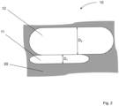
- Fig. 2 shows a pressure vessel system 10 according to the invention.
- a first pressure vessel 11 and a second pressure vessel 12 are installed in a vehicle chassis 20.
- the vehicle chassis 20 is shaped such that the second pressure vessel 12 has a diameter D 2 and the first pressure vessel 11 has a diameter D 1 , the first diameter D 1 being smaller than the second diameter D 2 .
- the first pressure vessel 11 has a first volume V 1 and the second pressure vessel 12 has a second volume V 2 , the first volume V 1 being smaller than the second volume V 2 .
- the fuel in the second pressure vessel 12 has a temperature ⁇ 2 outside of a permissible temperature window TB previously defined by a lower limit temperature ⁇ g, u and an upper limit temperature ⁇ g, o , in particular a higher temperature ⁇ 2 than the upper limit temperature ⁇ g, o due to the compression work performed during filling, at least some of the fuel is initially removed from the first pressure vessel 11 before fuel is removed from the second pressure vessel 12. This allows the fuel in the second pressure vessel 12 to be given time to cool down to below the upper limit temperature ⁇ g, o via heat exchange with the environment. At least this way, any cooling device (not shown) for the fuel can be made smaller. Furthermore, energy for cooling the fuel can be minimized. In certain cases, it may even be possible to dispense with active fuel cooling altogether.
Landscapes
- Engineering & Computer Science (AREA)
- Mechanical Engineering (AREA)
- General Engineering & Computer Science (AREA)
- Filling Or Discharging Of Gas Storage Vessels (AREA)
Priority Applications (3)
| Application Number | Priority Date | Filing Date | Title |
|---|---|---|---|
| EP23179742.4A EP4477940B1 (fr) | 2023-06-16 | 2023-06-16 | Procédé de fonctionnement de réservoirs de gaz |
| PCT/EP2024/066707 WO2024256716A1 (fr) | 2023-06-16 | 2024-06-16 | Procédé de fonctionnement de réservoirs de gaz |
| KR1020267001117A KR20260026061A (ko) | 2023-06-16 | 2024-06-16 | 가스 저장기의 작동 방법 |
Applications Claiming Priority (1)
| Application Number | Priority Date | Filing Date | Title |
|---|---|---|---|
| EP23179742.4A EP4477940B1 (fr) | 2023-06-16 | 2023-06-16 | Procédé de fonctionnement de réservoirs de gaz |
Publications (2)
| Publication Number | Publication Date |
|---|---|
| EP4477940A1 true EP4477940A1 (fr) | 2024-12-18 |
| EP4477940B1 EP4477940B1 (fr) | 2026-04-15 |
Family
ID=86861746
Family Applications (1)
| Application Number | Title | Priority Date | Filing Date |
|---|---|---|---|
| EP23179742.4A Active EP4477940B1 (fr) | 2023-06-16 | 2023-06-16 | Procédé de fonctionnement de réservoirs de gaz |
Country Status (3)
| Country | Link |
|---|---|
| EP (1) | EP4477940B1 (fr) |
| KR (1) | KR20260026061A (fr) |
| WO (1) | WO2024256716A1 (fr) |
Citations (4)
| Publication number | Priority date | Publication date | Assignee | Title |
|---|---|---|---|---|
| US20160290561A1 (en) * | 2013-11-18 | 2016-10-06 | Mosaic Technology Development Pty Ltd | System and method for intelligent refuelling of a pressurised vessel |
| DE102018000756A1 (de) * | 2018-01-31 | 2019-01-24 | Daimler Ag | Druckgasbehälter und Druckgasspeicher |
| US20210094409A1 (en) * | 2019-09-26 | 2021-04-01 | Toyota Jidosha Kabushiki Kaisha | Gas supply system and control method of gas supply system |
| DE102021103105A1 (de) * | 2021-02-10 | 2022-08-11 | Bayerische Motoren Werke Aktiengesellschaft | Vorrichtung und Verfahren zur Angleichung von Druckunterschieden in einem Mehrbehältersystem |
-
2023
- 2023-06-16 EP EP23179742.4A patent/EP4477940B1/fr active Active
-
2024
- 2024-06-16 WO PCT/EP2024/066707 patent/WO2024256716A1/fr not_active Ceased
- 2024-06-16 KR KR1020267001117A patent/KR20260026061A/ko active Pending
Patent Citations (4)
| Publication number | Priority date | Publication date | Assignee | Title |
|---|---|---|---|---|
| US20160290561A1 (en) * | 2013-11-18 | 2016-10-06 | Mosaic Technology Development Pty Ltd | System and method for intelligent refuelling of a pressurised vessel |
| DE102018000756A1 (de) * | 2018-01-31 | 2019-01-24 | Daimler Ag | Druckgasbehälter und Druckgasspeicher |
| US20210094409A1 (en) * | 2019-09-26 | 2021-04-01 | Toyota Jidosha Kabushiki Kaisha | Gas supply system and control method of gas supply system |
| DE102021103105A1 (de) * | 2021-02-10 | 2022-08-11 | Bayerische Motoren Werke Aktiengesellschaft | Vorrichtung und Verfahren zur Angleichung von Druckunterschieden in einem Mehrbehältersystem |
Also Published As
| Publication number | Publication date |
|---|---|
| KR20260026061A (ko) | 2026-02-25 |
| EP4477940B1 (fr) | 2026-04-15 |
| WO2024256716A1 (fr) | 2024-12-19 |
Similar Documents
| Publication | Publication Date | Title |
|---|---|---|
| DE102020206689B3 (de) | Kryogen-Speichersystem | |
| EP3497361B1 (fr) | Procédé permettant de régler la température et/ou la pression d'un combustible, en particulier d'hydrogène, dans plusieurs récipients sous pression d'un véhicule à respectivement une valeur de consigne de température et/ou à respectivement une valeur de consigne de pression avant une opération de remplissage des récipients sous pression | |
| EP2831491B1 (fr) | Procédé pour faire fonctionner un réservoir sous pression cryogénique | |
| EP3722652B1 (fr) | Récipient de stockage pour gaz liquéfié à très basse température | |
| DE102012204819A1 (de) | Betriebsverfahren für eine Brennstoffzellen-Anlage | |
| DE102021207190A1 (de) | Verfahren zum Ansteuern einer Tankvorrichtung und Tankvorrichtung zur Speicherung eines gasförmigen Mediums | |
| DE102009049687A1 (de) | Gasbehälteranordnung und Verfahren zum Betreiben einer Gasbehälteranordnung | |
| DE4445183A1 (de) | Betankungsverfahren für kryogene Flüssigkeiten | |
| DE102008063566A1 (de) | Gasdruckregler mit integrierter Beheizung | |
| DE102011117158B4 (de) | Tanksystem für ein Kraftfahrzeug sowie Betriebsverfahren hierfür | |
| WO2002053966A2 (fr) | Recipient pressurise a regulation integree d'un fluide comprime | |
| EP4073416A1 (fr) | Dispositif de remplissage servant à remplir des réservoirs de stockage avec de l'hydrogène comprimé, station-service comprenant celui-ci et procédé de remplissage d'un réservoir de stockage | |
| DE102008063563A1 (de) | Kraftstoffversorgungssystem mit einem Tieftemperaturtank | |
| EP4402401A1 (fr) | Dispositif et procédé pour remplir un réservoir de véhicule avec de l'hydrogène gazeux comprimé | |
| EP1087174A2 (fr) | Procédé pour décharger un fluide cryogénique gazeux ou liquide d'un réservoir et réservoir correspondant | |
| DE19704362C1 (de) | Betankungseinrichtung für kryogene Kraftstoffe und Verfahren zum Betanken von Fahrzeugen jeder Art mit unterkühlter Flüssigkeit aus einer derartigen Betankungseinrichtung | |
| EP4477940B1 (fr) | Procédé de fonctionnement de réservoirs de gaz | |
| DE102022208072A1 (de) | Ventilbaugruppe für einen Brenngastank, Brenngastank mit Ventilbaugruppe sowie Brenngastanksystem | |
| DE102019122227B4 (de) | Wasserstoffsystem für eine mobile Einheit sowie Verfahren zum Betreiben eines Wasserstoffsystems, Steuerungsprogramm und computerlesbares Speichermedium | |
| EP1090251A1 (fr) | Systeme pour alimenter un consommateur avec un milieu cryogenique | |
| DE102021204897A1 (de) | Tankventileinrichtung für zumindest einen Tankbehälter, Tankvorrichtung zum Speichern eines Treibstoffs und Verfahren zum Betreiben einer Tankvorrichtung | |
| DE102012013015A1 (de) | Verfahren und Vorrichtung zum Betanken eines Fahrzeugs mit einem Fluid und zum Kühlen des Fluids in einem Tank des Fahrzeugs | |
| DE102022109097A1 (de) | Verfahren und Vorrichtung zur Versorgung von Verbrauchern mit Wasserstoff | |
| DE102017217348A1 (de) | Druckbehältersystem und Verfahren zum Zuführen von Brennstoff aus einem Druckbehältersystem | |
| DE102024120384A1 (de) | Speichersystem für einen unter Druck stehenden gasförmigen Brennstoff |
Legal Events
| Date | Code | Title | Description |
|---|---|---|---|
| PUAI | Public reference made under article 153(3) epc to a published international application that has entered the european phase |
Free format text: ORIGINAL CODE: 0009012 |
|
| STAA | Information on the status of an ep patent application or granted ep patent |
Free format text: STATUS: THE APPLICATION HAS BEEN PUBLISHED |
|
| AK | Designated contracting states |
Kind code of ref document: A1 Designated state(s): AL AT BE BG CH CY CZ DE DK EE ES FI FR GB GR HR HU IE IS IT LI LT LU LV MC ME MK MT NL NO PL PT RO RS SE SI SK SM TR |
|
| STAA | Information on the status of an ep patent application or granted ep patent |
Free format text: STATUS: REQUEST FOR EXAMINATION WAS MADE |
|
| REG | Reference to a national code |
Ref country code: HK Ref legal event code: DE Ref document number: 40118564 Country of ref document: HK |
|
| 17P | Request for examination filed |
Effective date: 20250618 |
|
| GRAP | Despatch of communication of intention to grant a patent |
Free format text: ORIGINAL CODE: EPIDOSNIGR1 |
|
| STAA | Information on the status of an ep patent application or granted ep patent |
Free format text: STATUS: GRANT OF PATENT IS INTENDED |
|
| INTG | Intention to grant announced |
Effective date: 20251110 |
|
| GRAS | Grant fee paid |
Free format text: ORIGINAL CODE: EPIDOSNIGR3 |
|
| GRAA | (expected) grant |
Free format text: ORIGINAL CODE: 0009210 |
|
| STAA | Information on the status of an ep patent application or granted ep patent |
Free format text: STATUS: THE PATENT HAS BEEN GRANTED |
|
| AK | Designated contracting states |
Kind code of ref document: B1 Designated state(s): AL AT BE BG CH CY CZ DE DK EE ES FI FR GB GR HR HU IE IS IT LI LT LU LV MC ME MK MT NL NO PL PT RO RS SE SI SK SM TR |
|
| REG | Reference to a national code |
Ref country code: CH Ref legal event code: F10 Free format text: ST27 STATUS EVENT CODE: U-0-0-F10-F00 (AS PROVIDED BY THE NATIONAL OFFICE) Effective date: 20260415 |
|
| REG | Reference to a national code |
Ref country code: DE Ref legal event code: R096 Ref document number: 502023003741 Country of ref document: DE |