EP4477495A1 - Insassenstatuserkennungsvorrichtung und computerprogramm - Google Patents
Insassenstatuserkennungsvorrichtung und computerprogramm Download PDFInfo
- Publication number
- EP4477495A1 EP4477495A1 EP23752732.0A EP23752732A EP4477495A1 EP 4477495 A1 EP4477495 A1 EP 4477495A1 EP 23752732 A EP23752732 A EP 23752732A EP 4477495 A1 EP4477495 A1 EP 4477495A1
- Authority
- EP
- European Patent Office
- Prior art keywords
- grip
- determining unit
- touchpad
- determination
- steering wheel
- Prior art date
- Legal status (The legal status is an assumption and is not a legal conclusion. Google has not performed a legal analysis and makes no representation as to the accuracy of the status listed.)
- Pending
Links
Images


Classifications
-
- B—PERFORMING OPERATIONS; TRANSPORTING
- B62—LAND VEHICLES FOR TRAVELLING OTHERWISE THAN ON RAILS
- B62D—MOTOR VEHICLES; TRAILERS
- B62D1/00—Steering controls, i.e. means for initiating a change of direction of the vehicle
- B62D1/02—Steering controls, i.e. means for initiating a change of direction of the vehicle vehicle-mounted
- B62D1/04—Hand wheels
- B62D1/06—Rims, e.g. with heating means; Rim covers
-
- B—PERFORMING OPERATIONS; TRANSPORTING
- B60—VEHICLES IN GENERAL
- B60R—VEHICLES, VEHICLE FITTINGS, OR VEHICLE PARTS, NOT OTHERWISE PROVIDED FOR
- B60R16/00—Electric or fluid circuits specially adapted for vehicles and not otherwise provided for; Arrangement of elements of electric or fluid circuits specially adapted for vehicles and not otherwise provided for
- B60R16/02—Electric or fluid circuits specially adapted for vehicles and not otherwise provided for; Arrangement of elements of electric or fluid circuits specially adapted for vehicles and not otherwise provided for electric constitutive elements
- B60R16/023—Electric or fluid circuits specially adapted for vehicles and not otherwise provided for; Arrangement of elements of electric or fluid circuits specially adapted for vehicles and not otherwise provided for electric constitutive elements for transmission of signals between vehicle parts or subsystems
- B60R16/027—Electric or fluid circuits specially adapted for vehicles and not otherwise provided for; Arrangement of elements of electric or fluid circuits specially adapted for vehicles and not otherwise provided for electric constitutive elements for transmission of signals between vehicle parts or subsystems between relatively movable parts of the vehicle, e.g. between steering wheel and column
-
- B—PERFORMING OPERATIONS; TRANSPORTING
- B60—VEHICLES IN GENERAL
- B60K—ARRANGEMENT OR MOUNTING OF PROPULSION UNITS OR OF TRANSMISSIONS IN VEHICLES; ARRANGEMENT OR MOUNTING OF PLURAL DIVERSE PRIME-MOVERS IN VEHICLES; AUXILIARY DRIVES FOR VEHICLES; INSTRUMENTATION OR DASHBOARDS FOR VEHICLES; ARRANGEMENTS IN CONNECTION WITH COOLING, AIR INTAKE, GAS EXHAUST OR FUEL SUPPLY OF PROPULSION UNITS IN VEHICLES
- B60K35/00—Instruments specially adapted for vehicles; Arrangement of instruments in or on vehicles
- B60K35/10—Input arrangements, i.e. from user to vehicle, associated with vehicle functions or specially adapted therefor
-
- B—PERFORMING OPERATIONS; TRANSPORTING
- B62—LAND VEHICLES FOR TRAVELLING OTHERWISE THAN ON RAILS
- B62D—MOTOR VEHICLES; TRAILERS
- B62D1/00—Steering controls, i.e. means for initiating a change of direction of the vehicle
- B62D1/02—Steering controls, i.e. means for initiating a change of direction of the vehicle vehicle-mounted
- B62D1/04—Hand wheels
- B62D1/046—Adaptations on rotatable parts of the steering wheel for accommodation of switches
-
- G—PHYSICS
- G01—MEASURING; TESTING
- G01V—GEOPHYSICS; GRAVITATIONAL MEASUREMENTS; DETECTING MASSES OR OBJECTS; TAGS
- G01V3/00—Electric or magnetic prospecting or detecting; Measuring magnetic field characteristics of the earth, e.g. declination, deviation
- G01V3/08—Electric or magnetic prospecting or detecting; Measuring magnetic field characteristics of the earth, e.g. declination, deviation operating with magnetic or electric fields produced or modified by objects or geological structures or by detecting devices
- G01V3/088—Electric or magnetic prospecting or detecting; Measuring magnetic field characteristics of the earth, e.g. declination, deviation operating with magnetic or electric fields produced or modified by objects or geological structures or by detecting devices operating with electric fields
-
- G—PHYSICS
- G06—COMPUTING OR CALCULATING; COUNTING
- G06F—ELECTRIC DIGITAL DATA PROCESSING
- G06F3/00—Input arrangements for transferring data to be processed into a form capable of being handled by the computer; Output arrangements for transferring data from processing unit to output unit, e.g. interface arrangements
- G06F3/01—Input arrangements or combined input and output arrangements for interaction between user and computer
- G06F3/03—Arrangements for converting the position or the displacement of a member into a coded form
- G06F3/033—Pointing devices displaced or positioned by the user, e.g. mice, trackballs, pens or joysticks; Accessories therefor
- G06F3/0354—Pointing devices displaced or positioned by the user, e.g. mice, trackballs, pens or joysticks; Accessories therefor with detection of two-dimensional [2D] relative movements between the device, or an operating part thereof, and a plane or surface, e.g. 2D mice, trackballs, pens or pucks
- G06F3/03547—Touch pads, in which fingers can move on a surface
-
- G—PHYSICS
- G06—COMPUTING OR CALCULATING; COUNTING
- G06F—ELECTRIC DIGITAL DATA PROCESSING
- G06F3/00—Input arrangements for transferring data to be processed into a form capable of being handled by the computer; Output arrangements for transferring data from processing unit to output unit, e.g. interface arrangements
- G06F3/01—Input arrangements or combined input and output arrangements for interaction between user and computer
- G06F3/03—Arrangements for converting the position or the displacement of a member into a coded form
- G06F3/041—Digitisers, e.g. for touch screens or touch pads, characterised by the transducing means
- G06F3/0416—Control or interface arrangements specially adapted for digitisers
-
- G—PHYSICS
- G06—COMPUTING OR CALCULATING; COUNTING
- G06F—ELECTRIC DIGITAL DATA PROCESSING
- G06F3/00—Input arrangements for transferring data to be processed into a form capable of being handled by the computer; Output arrangements for transferring data from processing unit to output unit, e.g. interface arrangements
- G06F3/01—Input arrangements or combined input and output arrangements for interaction between user and computer
- G06F3/03—Arrangements for converting the position or the displacement of a member into a coded form
- G06F3/041—Digitisers, e.g. for touch screens or touch pads, characterised by the transducing means
- G06F3/044—Digitisers, e.g. for touch screens or touch pads, characterised by the transducing means by capacitive means
-
- B—PERFORMING OPERATIONS; TRANSPORTING
- B60—VEHICLES IN GENERAL
- B60K—ARRANGEMENT OR MOUNTING OF PROPULSION UNITS OR OF TRANSMISSIONS IN VEHICLES; ARRANGEMENT OR MOUNTING OF PLURAL DIVERSE PRIME-MOVERS IN VEHICLES; AUXILIARY DRIVES FOR VEHICLES; INSTRUMENTATION OR DASHBOARDS FOR VEHICLES; ARRANGEMENTS IN CONNECTION WITH COOLING, AIR INTAKE, GAS EXHAUST OR FUEL SUPPLY OF PROPULSION UNITS IN VEHICLES
- B60K2360/00—Indexing scheme associated with groups B60K35/00 or B60K37/00 relating to details of instruments or dashboards
- B60K2360/143—Touch sensitive instrument input devices
- B60K2360/1434—Touch panels
-
- B—PERFORMING OPERATIONS; TRANSPORTING
- B60—VEHICLES IN GENERAL
- B60K—ARRANGEMENT OR MOUNTING OF PROPULSION UNITS OR OF TRANSMISSIONS IN VEHICLES; ARRANGEMENT OR MOUNTING OF PLURAL DIVERSE PRIME-MOVERS IN VEHICLES; AUXILIARY DRIVES FOR VEHICLES; INSTRUMENTATION OR DASHBOARDS FOR VEHICLES; ARRANGEMENTS IN CONNECTION WITH COOLING, AIR INTAKE, GAS EXHAUST OR FUEL SUPPLY OF PROPULSION UNITS IN VEHICLES
- B60K2360/00—Indexing scheme associated with groups B60K35/00 or B60K37/00 relating to details of instruments or dashboards
- B60K2360/77—Instrument locations other than the dashboard
- B60K2360/782—Instrument locations other than the dashboard on the steering wheel
Definitions
- the present invention relates to an occupant state detecting device and to a computer program.
- HMI human machine interface
- Patent Document 1 discloses a steering wheel that is configured to determine an operation direction based on a start area and an end area when a tracing operation is detected across a plurality of regions defined on an operation surface of a steering wheel, and determines the operation direction by adjusting the plurality of areas depending on the gripping position of a ring portion.
- Patent Document 1 Japanese Unexamined Patent Application Publication 2019-166878
- many steering wheels are provided with a gripping sensor that monitors the gripping state in addition to the aforementioned touchpad.
- Patent Document 1 also has both a touchpad and a gripping sensor, but Patent Document 1 does not devise a solution to this problem and is therefore unable to solve them.
- an object of the present invention is to provide an occupant state detecting device and a computer program that can prevent normal operation from being impaired when the gripping sensor and touchpad are operated simultaneously in an occupant state detection device that has both a touchpad and a gripping sensor.
- the occupant state detecting device of the present invention contains: a steering wheel having a touch pad operable using electrostatic capacitance and a gripping sensor for detecting whether a driver is gripping a rim part; an operation determining unit for performing an operation determination as to whether the touch pad is being operated; and a grip determining unit for performing grip determination as to whether the rim part of the steering wheel is being gripped.
- the grip determining unit performs grip determination depending on a result of the operation determination. For example, when the operation determining unit determines that the touchpad is being operated, the grip determining unit does not perform grip determination in order to prevent interference between the operation determination and the grip determination.
- the computer program of the present invention causes a computer to execute a process that performs an operation determination as to whether a touchpad operable using electrostatic capacitance provided on a steering wheel is being operated and a grip determination as to whether the rim part of the steering wheel is being gripped.
- grip determination is performed depending on the result of the operation determination. For example, when a determination is made that the touchpad is being operated, grip determination is not performed in order to prevent interference between the operation determination and the grip determination.
- the present invention can prevent a malfunction when the gripping sensor and the touchpad are operated simultaneously in an occupant state detecting device having both a touchpad and a gripping sensor.
- the occupant state detecting device according to an embodiment of the present invention is described below in detail with reference to the drawings, using a steering wheel device as an example.
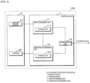
- FIG. 1 is a block diagram depicting an example configuration of a steering wheel device 100 according to the present embodiment.
- the steering wheel device 100 (occupant state detecting device) includes a steering wheel 2, a control device 1, and the like.
- the control device 1 is communicatively connected to various ECUs, such as a driving assistance ECU that executes processes related to an advanced driving assistance system, via an in-vehicle network provided in the vehicle.
- the steering wheel 2 includes a gripping sensor 21 and a touchpad 20.
- the gripping sensor 21 and the touchpad 20 detect electrostatic capacitance coupled to an electrode provided on the steering wheel 2, for example.
- the control device 1 is provided on, for example, a steering wheel 2, and includes a grip determining unit 11, an operation determining unit 12, and a communication unit 13.
- the grip determining unit 11 acquires a detection value of the electrostatic capacitance detected by the gripping sensor 21, and determines whether the steering wheel 2 is in a gripped state or a non-gripped state, based on the detection value.
- the hands-on state refers to a condition where the driver is gripping the steering wheel 2
- the hands-off state refers to a state where the driver has released and is not gripping the steering wheel 2.
- the grip determining unit 11 includes a processing unit (not depicted) such as a Central Processing Unit (CPU) or a Micro Processing Unit (MPU). In addition, as described above, the grip determining unit 11 determines whether the steering wheel 2 is in a gripped state or a non-gripped state (hereinafter referred to as grip determination) based on the detection value of the electrostatic capacitance detected by the gripping sensor 21. Furthermore, as described later, the grip determining unit 11 also performs grip determination depending on whether or not the touchpad 20 is being operated by the driver. The result of the grip determination by the grip determining unit 11 is transmitted to the driving assistance ECU or the like via a communication unit 13.
- a processing unit such as a Central Processing Unit (CPU) or a Micro Processing Unit (MPU).
- the grip determining unit 11 determines whether the steering wheel 2 is in a gripped state or a non-gripped state (hereinafter referred to as grip determination) based on the detection value of the electrostatic capacitance detected by the gripping
- the grip determining unit 11 includes a capacitance measuring circuit (not depicted).
- the capacitance measuring circuit is an electric circuit for measuring a detected value of the electrostatic capacitance.
- the capacitance measuring circuit processes the electrical signal obtained from the gripping sensor 21 and calculates a detected value of the electrostatic capacitance.
- the grip determining unit 11 performs grip determination using the calculated electrostatic capacitance detection value.
- the grip determining unit 11 includes a storage unit 111.
- the storage unit 111 includes memory elements such as Random Access Memory (RAM) and Read Only Memory (ROM), and stores programs, data, and the like necessary for the grip determining unit 11 to perform processes.
- the storage unit 111 temporarily stores data or the like necessary for the grip determining unit 11 to perform processes.
- the storage unit 111 stores an electrostatic capacitance threshold value used when the grip determining unit 11 performs grip determination.
- the communication unit 13 is a communication interface for transmitting and receiving with other on-board devices such as various ECUs or the like via an in-vehicle network.
- the communication unit 13 is connected to a Local Area Network (LAN) provided in-vehicle, and transmits and receives information with other ECUs and the like.
- LAN Local Area Network
- the communication unit 13 transmits the result of the grip determination by the grip determining unit 11 to a driving assistance ECU or the like.
- the operation determining unit 12 generates operation instructions for operating a UI (User Interface) displayed on a display unit provided on a HUD (Head Up Display), an instrument panel, or a center console, on the basis of the electrostatic capacitance value sent from the touchpad 20.
- UI User Interface
- HUD Head Up Display
- Such an operation instruction is transmitted via the communication unit 13 to an ECU associated with the HUD, the instrument panel, or the center console.
- the operation determining unit 12 includes a storage unit 121.
- the storage unit 121 is similar to the storage unit 111, and a detailed description thereof is omitted.
- the storage unit 121 also stores the electrostatic capacitance threshold value used when determining whether or not the touchpad 20 is being operated (hereinafter, referred to as operation determination).
- the operation determining unit 12 performs the operation determination by comparing the electrostatic capacitance value sent from the touchpad 20 with a threshold value stored in the storage unit 121. In addition, if the operation determining unit 12 determines, as a result of the operation determination, that the touchpad 20 is being operated, a first operation determining signal is transmitted to the grip determining unit 11, and if a determination is made that the touchpad 20 is not being operated, a second operation determining signal is transmitted to the grip determining unit 11.
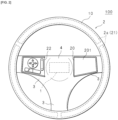
- FIG. 2 is a front view of the steering wheel 2 of the steering wheel device 100 according to the present embodiment.
- the gripping sensor 21 detects a change in electrostatic capacitance caused by contact between the hand of the driver and the steering wheel 2 (hereinafter referred to as electrostatic capacitance detection).
- the electrostatic capacitance detection is performed depending on whether or not the touchpad 20 is being operated by the driver.
- the gripping sensor 21 performs electrostatic capacitance detection depending on whether the operation determining unit 12 is issuing the first operation determining signal or the second operation determining signal.
- the gripping sensor 21 has a plurality of electrodes 2a provided inside the rim part 10 described below.
- the electrodes 2a are installed into each of three equal portions in the circumferential direction of the rim part 10.
- the number of electrodes 2a is not limited to three, but may be two or less, or four or more.
- the electrode 2a is connected to, for example, a C/V conversion circuit (not depicted) associated with the gripping sensor 21.
- the C/V conversion circuit applies an AC voltage of a predetermined amplitude to the electrode 2a, for example, and outputs an AC voltage according to the magnitude of the electrostatic capacitance coupled to the electrode 2a.
- the capacitance measuring circuit detects the electrostatic capacitance coupled to the electrode 2a by detecting the output voltage.
- the electrode 2a is electrically and capacitively coupled to the GND (ground) of the vehicle body or the like via the air in the vehicle compartment. If the steering wheel 2 is being gripped, or in other words, if the hands of the driver are in contact with the rim part 10, the electrode 2a comes close to the hands of the driver and is capacitively coupled with the body of the driver. When the electrode 2a is capacitively coupled to the GND, the electrostatic capacitance becomes very small due to the capacitive coupling with the ground surface. In this regard, the human body has a certain degree of conductivity, so the electrostatic capacitance due to coupling between the body of the driver and the electrode 2a is greater than the electrostatic capacitance due to coupling between the GND and the electrode 2a.
- the touchpad 20 is a known device in itself, in which a plurality of drive electrodes and a plurality of detection electrodes are provided crosswise while maintaining insulation on the rear side of an operation surface 201 (see FIG. 2 ), for example.
- the touchpad 20 detects a change in electrostatic capacitance caused by the fingertip of the driver touching the operation surface 201.
- a coordinate system is set on the operation surface 201, and receives an operation such as touching, tapping, and dragging by the fingertip of the driver.
- the touchpad 20 scans all the combinations of the drive electrodes and the detection electrodes and detects the electrostatic capacitance for each combination. The touchpad 20 then calculates the coordinates of the position related to the operation based on the threshold value in the storage unit 121. The touchpad 20 periodically outputs detection coordinates representing the calculated coordinates to the operation determining unit 12. The operation determining unit 12 generates an operation instruction for moving a cursor on the III of the display unit on the basis of the detected coordinates, an operation instruction for selecting any one of the selection keys, and the like.
- the touchpad 20 may be a mutual capacitance type touchpad, or may be configured as a self-capacitance type touchpad.
- the mutual capacitance method when a fingertip of the driver touches the operation surface 201, the electrostatic capacitance decreases compared to the case of capacitive coupling to the GND. Furthermore, in the case of the self-capacitance method, the electrostatic capacitance increases when the fingertip of the driver touches the operation surface 201.
- the touchpad 20 is a mutual capacitance type will be described below as an example.
- the steering wheel 2 includes a circular shaped rim part 10 and a hub part 4 provided at the center of the rim part 10 and has an airbag (not depicted) installed therein.
- the hub part 4 is connected to the rim part 10 by means of three spoke parts 3.
- the rim part 10 is covered with a surface skin material such as leather, and the hub part 4 and spoke parts 3 are covered with, for example, a resin material. As described above, three electrodes 2a are provided on the inside of the rim part 10 along the circumferential direction of the rim part 10.
- a rim part 10 having a circular shape will be used for the description, but the rim part of the present invention is not limited to this case.
- the rim part 10 may be non-circular (for example, D-shaped or C shaped).
- the spoke parts 3 are provided at the 3 o' clock position, the 6 o' clock position, and the 9 o' clock position in the clockwise direction.
- the resin member of the spoke part 3 at the 9 o'clock position is provided with an operation panel 22 having a plurality of operating buttons so that the driver can operate in-vehicle devices such as audio or the like while driving.
- a touchpad 20 is provided on an operating panel 22 provided on the spoke part 3 in the 3 o'clock direction.
- the touchpad 20 has a substantially rectangular, flat operation surface 201.
- the operation surface 201 accepts driver operations such as touching, tapping, and dragging.
- the touchpad 20 (operation surface 201) is provided near the rim part 10 and extends from the center of the steering wheel 2 to a portion of the spoke part 3.
- control device 1 performs grip determination on the basis of the voltage value (electrostatic capacitance) from the gripping sensor 21, as described above.
- the electrical signal indicating the electrostatic capacitance detected by the gripping sensor 21 is processed by the capacitance measuring circuit to obtain a detected value of the electrostatic capacitance.
- the grip determining unit 11 compares the acquired detection value (electrostatic capacitance) with a threshold value stored in the storage unit 111.
- the grip determining unit 11 performs grip determination as to whether or not the steering wheel 2 is in a gripped state on the basis of the detection value and the threshold value. For example, the grip determining unit 11 determines a non-gripped state if the acquired detection value is less than the threshold value, and determines a gripped state if the acquired detection value is equal to or greater than the threshold value. The result of the grip determination by the grip determining unit 11 is sent to the driving assistance ECU by the communication unit 13.
- the driving assistance ECU which receives a signal indicating the result of the grip determination from the control device 1, executes processes related to driving assistance on the basis of the received result of the grip determination. For example, if grip determination results indicating a hands-off state of the steering wheel 2 are received during autonomous driving, the driving assistance ECU terminates autonomous driving. Note that the driving assistance ECU processing is not limited to autonomous driving and may be lane keep assist, parking assist, or the like.
- FIG. 3 is an illustrative diagram depicting an example of operating a touchpad 20 in the steering wheel device 100 of the present embodiment. For convenience, the hands of the driver 200 are depicted by dashed lines in FIG. 3 .
- the touchpad 20 is provided close to the rim part 10, so the driver can operate the touchpad 20 with, for example, the tip of a thumb while gripping the rim part 10.
- the rim part 10 may be gripped and the touchpad 20 may be operated at the same time.
- both the touchpad 20 and the gripping sensor 21 are devices that measure electrostatic capacitance, there is a possibility that normal measurement may not be possible. Furthermore, this may lead to erroneous determinations in the grip determination and the operation determination, and may cause malfunctions of the UI of the display unit.
- the grip determining unit 11 performs grip determination depending on whether or not the touchpad 20 is being operated by the driver, thereby solving the aforementioned problem. The details are described below.
- FIG. 4 is a flowchart illustrating the operation determination and grip determination processes in the steering wheel device 100 of the present embodiment.
- the grip determining unit 11 determines whether or not the engine of the vehicle has started (step S201).
- the grip determining unit 11 performs a determination by monitoring an ignition signal output for a predetermined period of time when an ignition (ignition device) is ON.
- step S201: NO If the grip determining unit 11 determines that the engine of the vehicle has not started (step S201: NO), the determination is repeated. In addition, if the grip determining unit 11 determines that the vehicle engine has started (step S201: YES), grip determination starts based on the result of the electrostatic capacitance detection by the gripping sensor 21 (step S202). In other words, the grip determining unit 11 starts grip determination based on the electrostatic capacitance from the gripping sensor 21.
- the grip determining unit 11 transmits the result of the grip determination to the driving assistance ECU or the like via the communication unit 13 until the first operation determining signal is transmitted from the operation determining unit 12.
- the operation determining unit 12 monitors the ignition signal to determine whether the vehicle engine has started (step S101). If the operation determining unit 12 determines that the engine of the vehicle has not started (step S101: NO), the determination is repeated. Furthermore, if it is determined that the engine of the vehicle has started (step S101: YES), the operation determining unit 12 starts the operation determination (step S102). In other words, the operation determining unit 12 starts comparing the electrostatic capacitance value sent from the touchpad 20 to the threshold value stored in the storage unit 121.
- the operation determining unit 12 determines whether or not the touchpad 20 is being operated (step S103). When the operation determining unit 12 determines that the touchpad 20 is not being operated (step S103: NO), the determination is repeated. Furthermore, if the operation determining unit 12 determines that the touchpad 20 is being operated (step S103: YES), a first operation determining signal is transmitted to the grip determining unit 11 (step S104).
- the grip determining unit 11 If the grip determining unit 11 receives the first operation determining signal from the operation determining unit 12, the grip determining unit 11 suspends the grip determination being executed (step S203). In other words, the grip determining unit 11 invalidates the electrostatic capacitance sent from the gripping sensor 21.
- the grip determining unit 11 determines the grip state as a result of the grip determination, regardless of the result of the electrostatic capacitance detection from the gripping sensor 21 (step S204).
- the result of this grip determination is transmitted to the driving assistance ECU or the like via the communication unit 13.
- the grip determining unit 11 determines whether or not a second operation determining signal has been received from the operation determining unit 12 (step S205). If the grip determining unit 11 determines that the second operation determining signal has not been received from the operation determining unit 12 (step S205: NO), the process returns to step S204, and the grip determining unit 11 sets the result of the grip determination to a gripping state.
- the operation determining unit 12 determines whether a predetermined period of time has elapsed based on the timing result of a timing unit (not depicted) (step S105).
- step S105 determines that a predetermined period of time has not elapsed since transmitting the first operation determining signal. If the operation determining unit 12 determines that a predetermined period of time has not elapsed since transmitting the first operation determining signal (step S105: NO), the process returns to step S104, and the operation determining unit 12 transmits the first operation determining signal to the grip determining unit 11.
- step S105 determines that a predetermined period of time has elapsed since transmitting the first operation determining signal.
- a determination is made as to whether or not the touchpad 20 is being operated step S106. If the operation determining unit 12 determines that the touchpad 20 is being operated (step S106: YES), the process returns to step S104, and the operation determining unit 12 transmits a first operation determining signal to the grip determining unit 11.
- the operation determining unit 12 after transmitting the first operation determining signal, the operation determining unit 12 periodically repeats the determination of whether or not the touchpad 20 is being operated, and if a determination is made that the touchpad 20 is being operated, continues to transmit the first operation determining signal to the grip determining unit 11.
- step S106 determines that the touchpad 20 is not being operated
- step S107 a second operation determining signal is transmitted to the grip determining unit 11 (step S107). Thereafter, the process ends.
- the grip determining unit 11 determines that the second operation determining signal has been received (step S205: YES).
- the grip determining unit 11 resumes the suspended grip determination (step S206). In other words, the grip determining unit 11 resumes grip determination based on the electrostatic capacitance from the gripping sensor 21. Thereafter, the process ends.
- the aforementioned process is repeated, for example, until the engine of the vehicle is stopped.
- the grip determining unit 11 suspends the grip determination
- the operation determining unit 12 emits the second operation determining signal, or in other words, when the driver stops operating the touchpad 20
- the grip determining unit 11 resumes the grip judgment. Therefore, the gripping sensor 21 does not perform electrostatic capacitance detection while the driver is operating the touchpad 20, and is disabled. Therefore, a problem can be prevented beforehand in which normal electrostatic capacitance measurement is not possible due to electrical contact between the electrode 2a of the gripping sensor 21 and the electrode of the touchpad 20 via the hand of the driver.
- the grip determining unit 11 when the first operation determining signal is transmitted and the grip determination by the grip determining unit 11 is suspended, the grip determining unit 11 uniformly sets the result of the grip determination to a grip state, regardless of the result of the electrostatic capacitance detection from the gripping sensor 21.
- the gripping determination can be appropriately determined to be a gripping state. Therefore, even if the grip determination is suspended, an appropriate grip determination result can be output to a driving assistance ECU, or the like.
- control device 1 is built-in, so an in-vehicle LAN is not used. This reduces the strain on the data communication band of the vehicle-mounted LAN and improves responsiveness.
- control device 1 is provided on the steering wheel 2, but the present invention is not limited to this case.
- control device 1 may be provided on the main body side (for example, a controller) of the corresponding vehicle.
Landscapes
- Engineering & Computer Science (AREA)
- Theoretical Computer Science (AREA)
- General Engineering & Computer Science (AREA)
- Physics & Mathematics (AREA)
- Mechanical Engineering (AREA)
- General Physics & Mathematics (AREA)
- Transportation (AREA)
- Combustion & Propulsion (AREA)
- Chemical & Material Sciences (AREA)
- Human Computer Interaction (AREA)
- Remote Sensing (AREA)
- Life Sciences & Earth Sciences (AREA)
- Geology (AREA)
- Geophysics (AREA)
- Environmental & Geological Engineering (AREA)
- General Life Sciences & Earth Sciences (AREA)
- Electromagnetism (AREA)
- Steering Controls (AREA)
- Switches That Are Operated By Magnetic Or Electric Fields (AREA)
Applications Claiming Priority (2)
| Application Number | Priority Date | Filing Date | Title |
|---|---|---|---|
| JP2022018872 | 2022-02-09 | ||
| PCT/JP2023/002971 WO2023153267A1 (ja) | 2022-02-09 | 2023-01-31 | 乗員状態検知装置及びコンピュータプログラム |
Publications (2)
| Publication Number | Publication Date |
|---|---|
| EP4477495A1 true EP4477495A1 (de) | 2024-12-18 |
| EP4477495A4 EP4477495A4 (de) | 2026-01-07 |
Family
ID=87564217
Family Applications (1)
| Application Number | Title | Priority Date | Filing Date |
|---|---|---|---|
| EP23752732.0A Pending EP4477495A4 (de) | 2022-02-09 | 2023-01-31 | Insassenstatuserkennungsvorrichtung und computerprogramm |
Country Status (5)
| Country | Link |
|---|---|
| US (1) | US20250136168A1 (de) |
| EP (1) | EP4477495A4 (de) |
| JP (1) | JP7681735B2 (de) |
| CN (1) | CN118647540A (de) |
| WO (1) | WO2023153267A1 (de) |
Families Citing this family (1)
| Publication number | Priority date | Publication date | Assignee | Title |
|---|---|---|---|---|
| DE102024106688B3 (de) | 2024-03-08 | 2025-06-26 | Dr. Ing. H.C. F. Porsche Aktiengesellschaft | Lenkanordnung und Fahrzeug |
Family Cites Families (8)
| Publication number | Priority date | Publication date | Assignee | Title |
|---|---|---|---|---|
| JP2015047969A (ja) * | 2013-09-02 | 2015-03-16 | 本田技研工業株式会社 | スイッチシステム |
| JP6123590B2 (ja) * | 2013-09-05 | 2017-05-10 | 株式会社デンソー | タッチ検出装置および車両用ナビゲーション装置 |
| WO2017082372A1 (ja) * | 2015-11-13 | 2017-05-18 | オートリブ ディベロップメント エービー | プログラム及び制御装置 |
| DE102016124592A1 (de) * | 2016-12-16 | 2018-06-21 | Valeo Schalter Und Sensoren Gmbh | Sensoreinrichtung für ein Fahrzeug und Verfahren zum Betrieb einer solchen Sensoreinrichtung |
| JP6824129B2 (ja) * | 2017-09-01 | 2021-02-03 | 株式会社東海理化電機製作所 | 操作装置 |
| JP6596743B2 (ja) * | 2017-12-28 | 2019-10-30 | 本田技研工業株式会社 | 車両用ステアリング装置 |
| JP2019166878A (ja) | 2018-03-22 | 2019-10-03 | 株式会社東海理化電機製作所 | タッチパッド及び操作システム |
| KR20210132316A (ko) * | 2020-04-27 | 2021-11-04 | 현대자동차주식회사 | 차량 주행 보조 제어 장치 및 방법 |
-
2023
- 2023-01-31 EP EP23752732.0A patent/EP4477495A4/de active Pending
- 2023-01-31 JP JP2023580183A patent/JP7681735B2/ja active Active
- 2023-01-31 US US18/835,563 patent/US20250136168A1/en active Pending
- 2023-01-31 CN CN202380019882.3A patent/CN118647540A/zh active Pending
- 2023-01-31 WO PCT/JP2023/002971 patent/WO2023153267A1/ja not_active Ceased
Also Published As
| Publication number | Publication date |
|---|---|
| CN118647540A (zh) | 2024-09-13 |
| US20250136168A1 (en) | 2025-05-01 |
| EP4477495A4 (de) | 2026-01-07 |
| JP7681735B2 (ja) | 2025-05-22 |
| WO2023153267A1 (ja) | 2023-08-17 |
| JPWO2023153267A1 (de) | 2023-08-17 |
Similar Documents
| Publication | Publication Date | Title |
|---|---|---|
| US8736432B2 (en) | Touch sensor having a selectable sensitivity level and method of selecting a sensitivity level of a touch sensor | |
| EP2786902B1 (de) | Fahrzeugbetätigungsvorrichtung | |
| US20200167116A1 (en) | Vehicle display device, and vehicle display method | |
| EP2998840B1 (de) | Kapazitive berührungssensorvorrichtung und -steuerung | |
| US20080192024A1 (en) | Operator distinguishing device | |
| CN109923020B (zh) | 方向盘单元 | |
| US10289249B2 (en) | Input device | |
| US11928288B2 (en) | Operation input device, operation input method, and non-transitory computer-readable medium storing operation input program | |
| EP3040252B1 (de) | Lenkradsteuerungssystem | |
| JP6233248B2 (ja) | 把持状態判定装置、把持状態判定方法、入力装置、入力取得方法 | |
| CN114222694A (zh) | 利用方向盘中的双区传感器检测手握持的设备和方法 | |
| US20160202762A1 (en) | Touch panel type input device, and touch panel type input method | |
| CN105358380B (zh) | 输入装置 | |
| CN106662977A (zh) | 用于在多手指操纵的情况下运行机动车的操纵装置的方法 | |
| EP4477495A1 (de) | Insassenstatuserkennungsvorrichtung und computerprogramm | |
| WO2016189734A1 (ja) | タッチパネル制御装置及び車載情報機器 | |
| US20210001914A1 (en) | Vehicle input device | |
| EP4015348B1 (de) | Verfahren zur bestimmung des zustands eines fahrers | |
| CN120697771A (zh) | 方向盘离手检测方法、设备、存储介质、程序产品及车辆 | |
| JP2020185861A (ja) | タッチセンサの信号処理装置、タッチセンサと信号処理装置とを備える操作装置、タッチセンサの信号処理方法 | |
| KR101922454B1 (ko) | 전하량 변화를 이용한 제스처 인식 시스템 및 방법 | |
| US20230174135A1 (en) | Assessment device, storage medium storing computer program for assessment, and assessment method | |
| US11608102B2 (en) | Vehicle and in-vehicle control method | |
| CN111376857A (zh) | 车辆控制方法、装置、电子设备和计算机存储介质 | |
| JP2022073761A (ja) | 車両運転システム |
Legal Events
| Date | Code | Title | Description |
|---|---|---|---|
| STAA | Information on the status of an ep patent application or granted ep patent |
Free format text: STATUS: THE INTERNATIONAL PUBLICATION HAS BEEN MADE |
|
| PUAI | Public reference made under article 153(3) epc to a published international application that has entered the european phase |
Free format text: ORIGINAL CODE: 0009012 |
|
| STAA | Information on the status of an ep patent application or granted ep patent |
Free format text: STATUS: REQUEST FOR EXAMINATION WAS MADE |
|
| 17P | Request for examination filed |
Effective date: 20240826 |
|
| AK | Designated contracting states |
Kind code of ref document: A1 Designated state(s): AL AT BE BG CH CY CZ DE DK EE ES FI FR GB GR HR HU IE IS IT LI LT LU LV MC ME MK MT NL NO PL PT RO RS SE SI SK SM TR |
|
| DAV | Request for validation of the european patent (deleted) | ||
| DAX | Request for extension of the european patent (deleted) | ||
| A4 | Supplementary search report drawn up and despatched |
Effective date: 20251210 |
|
| RIC1 | Information provided on ipc code assigned before grant |
Ipc: B62D 1/08 20060101AFI20251204BHEP Ipc: B60R 16/027 20060101ALI20251204BHEP Ipc: G06F 3/01 20060101ALI20251204BHEP |