EP4477487A2 - Elektrische architektur zur versorgung einer transportkühleinheit - Google Patents
Elektrische architektur zur versorgung einer transportkühleinheit Download PDFInfo
- Publication number
- EP4477487A2 EP4477487A2 EP24193739.0A EP24193739A EP4477487A2 EP 4477487 A2 EP4477487 A2 EP 4477487A2 EP 24193739 A EP24193739 A EP 24193739A EP 4477487 A2 EP4477487 A2 EP 4477487A2
- Authority
- EP
- European Patent Office
- Prior art keywords
- power
- converter
- energy storage
- grid
- bus
- Prior art date
- Legal status (The legal status is an assumption and is not a legal conclusion. Google has not performed a legal analysis and makes no representation as to the accuracy of the status listed.)
- Pending
Links
Images


Classifications
-
- B—PERFORMING OPERATIONS; TRANSPORTING
- B60—VEHICLES IN GENERAL
- B60H—ARRANGEMENTS OF HEATING, COOLING, VENTILATING OR OTHER AIR-TREATING DEVICES SPECIALLY ADAPTED FOR PASSENGER OR GOODS SPACES OF VEHICLES
- B60H1/00—Heating, cooling or ventilating devices
- B60H1/00007—Combined heating, ventilating, or cooling devices
- B60H1/00014—Combined heating, ventilating, or cooling devices for load cargos on load transporting vehicles
-
- B—PERFORMING OPERATIONS; TRANSPORTING
- B60—VEHICLES IN GENERAL
- B60H—ARRANGEMENTS OF HEATING, COOLING, VENTILATING OR OTHER AIR-TREATING DEVICES SPECIALLY ADAPTED FOR PASSENGER OR GOODS SPACES OF VEHICLES
- B60H1/00—Heating, cooling or ventilating devices
- B60H1/00357—Air-conditioning arrangements specially adapted for particular vehicles
- B60H1/00364—Air-conditioning arrangements specially adapted for particular vehicles for caravans or trailers
-
- B—PERFORMING OPERATIONS; TRANSPORTING
- B60—VEHICLES IN GENERAL
- B60H—ARRANGEMENTS OF HEATING, COOLING, VENTILATING OR OTHER AIR-TREATING DEVICES SPECIALLY ADAPTED FOR PASSENGER OR GOODS SPACES OF VEHICLES
- B60H1/00—Heating, cooling or ventilating devices
- B60H1/00421—Driving arrangements for parts of a vehicle air-conditioning
- B60H1/00428—Driving arrangements for parts of a vehicle air-conditioning electric
-
- B—PERFORMING OPERATIONS; TRANSPORTING
- B60—VEHICLES IN GENERAL
- B60H—ARRANGEMENTS OF HEATING, COOLING, VENTILATING OR OTHER AIR-TREATING DEVICES SPECIALLY ADAPTED FOR PASSENGER OR GOODS SPACES OF VEHICLES
- B60H1/00—Heating, cooling or ventilating devices
- B60H1/32—Cooling devices
- B60H1/3204—Cooling devices using compression
- B60H1/3232—Cooling devices using compression particularly adapted for load transporting vehicles
-
- B—PERFORMING OPERATIONS; TRANSPORTING
- B60—VEHICLES IN GENERAL
- B60K—ARRANGEMENT OR MOUNTING OF PROPULSION UNITS OR OF TRANSMISSIONS IN VEHICLES; ARRANGEMENT OR MOUNTING OF PLURAL DIVERSE PRIME-MOVERS IN VEHICLES; AUXILIARY DRIVES FOR VEHICLES; INSTRUMENTATION OR DASHBOARDS FOR VEHICLES; ARRANGEMENTS IN CONNECTION WITH COOLING, AIR INTAKE, GAS EXHAUST OR FUEL SUPPLY OF PROPULSION UNITS IN VEHICLES
- B60K11/00—Arrangement in connection with cooling of propulsion units
- B60K11/06—Arrangement in connection with cooling of propulsion units with air cooling
-
- F—MECHANICAL ENGINEERING; LIGHTING; HEATING; WEAPONS; BLASTING
- F25—REFRIGERATION OR COOLING; COMBINED HEATING AND REFRIGERATION SYSTEMS; HEAT PUMP SYSTEMS; MANUFACTURE OR STORAGE OF ICE; LIQUEFACTION SOLIDIFICATION OF GASES
- F25D—REFRIGERATORS; COLD ROOMS; ICE-BOXES; COOLING OR FREEZING APPARATUS NOT OTHERWISE PROVIDED FOR
- F25D29/00—Arrangement or mounting of control or safety devices
- F25D29/003—Arrangement or mounting of control or safety devices for movable devices
-
- H—ELECTRICITY
- H02—GENERATION; CONVERSION OR DISTRIBUTION OF ELECTRIC POWER
- H02J—ELECTRIC POWER NETWORKS; CIRCUIT ARRANGEMENTS OR SYSTEMS FOR SUPPLYING OR DISTRIBUTING ELECTRIC POWER; SYSTEMS FOR STORING ELECTRIC ENERGY
- H02J1/00—Circuit arrangements for DC mains or DC distribution networks
- H02J1/10—Parallel operation of DC sources
- H02J1/102—Parallel operation of DC sources being switching converters
-
- H—ELECTRICITY
- H02—GENERATION; CONVERSION OR DISTRIBUTION OF ELECTRIC POWER
- H02J—ELECTRIC POWER NETWORKS; CIRCUIT ARRANGEMENTS OR SYSTEMS FOR SUPPLYING OR DISTRIBUTING ELECTRIC POWER; SYSTEMS FOR STORING ELECTRIC ENERGY
- H02J3/00—Circuit arrangements for AC mains or AC distribution networks
- H02J3/28—Arrangements for balancing of the load in networks by storage of energy
- H02J3/32—Arrangements for balancing of the load in networks by storage of energy using batteries or super capacitors with converting means
-
- H—ELECTRICITY
- H02—GENERATION; CONVERSION OR DISTRIBUTION OF ELECTRIC POWER
- H02J—ELECTRIC POWER NETWORKS; CIRCUIT ARRANGEMENTS OR SYSTEMS FOR SUPPLYING OR DISTRIBUTING ELECTRIC POWER; SYSTEMS FOR STORING ELECTRIC ENERGY
- H02J7/00—Circuit arrangements for charging or discharging batteries or for supplying loads from batteries
- H02J7/14—Circuit arrangements for charging or discharging batteries or for supplying loads from batteries for charging batteries from dynamo-electric generators driven at varying speed, e.g. on vehicle
- H02J7/1415—Circuit arrangements for charging or discharging batteries or for supplying loads from batteries for charging batteries from dynamo-electric generators driven at varying speed, e.g. on vehicle with a generator driven by a prime mover other than the motor of a vehicle
-
- B—PERFORMING OPERATIONS; TRANSPORTING
- B60—VEHICLES IN GENERAL
- B60H—ARRANGEMENTS OF HEATING, COOLING, VENTILATING OR OTHER AIR-TREATING DEVICES SPECIALLY ADAPTED FOR PASSENGER OR GOODS SPACES OF VEHICLES
- B60H1/00—Heating, cooling or ventilating devices
- B60H1/32—Cooling devices
- B60H2001/3236—Cooling devices information from a variable is obtained
- B60H2001/3255—Cooling devices information from a variable is obtained related to temperature
- B60H2001/3261—Cooling devices information from a variable is obtained related to temperature of the air at an evaporating unit
-
- B—PERFORMING OPERATIONS; TRANSPORTING
- B60—VEHICLES IN GENERAL
- B60H—ARRANGEMENTS OF HEATING, COOLING, VENTILATING OR OTHER AIR-TREATING DEVICES SPECIALLY ADAPTED FOR PASSENGER OR GOODS SPACES OF VEHICLES
- B60H1/00—Heating, cooling or ventilating devices
- B60H1/32—Cooling devices
- B60H2001/3286—Constructional features
- B60H2001/3292—Compressor drive is electric only
-
- B—PERFORMING OPERATIONS; TRANSPORTING
- B60—VEHICLES IN GENERAL
- B60Y—INDEXING SCHEME RELATING TO ASPECTS CROSS-CUTTING VEHICLE TECHNOLOGY
- B60Y2200/00—Type of vehicle
- B60Y2200/10—Road Vehicles
- B60Y2200/14—Trucks; Load vehicles, Busses
- B60Y2200/147—Trailers, e.g. full trailers or caravans
-
- H—ELECTRICITY
- H02—GENERATION; CONVERSION OR DISTRIBUTION OF ELECTRIC POWER
- H02J—ELECTRIC POWER NETWORKS; CIRCUIT ARRANGEMENTS OR SYSTEMS FOR SUPPLYING OR DISTRIBUTING ELECTRIC POWER; SYSTEMS FOR STORING ELECTRIC ENERGY
- H02J2105/00—Networks for supplying or distributing electric power characterised by their spatial reach or by the load
- H02J2105/30—Networks for supplying or distributing electric power characterised by their spatial reach or by the load the load networks being external to vehicles, i.e. exchanging power with vehicles
- H02J2105/33—Networks for supplying or distributing electric power characterised by their spatial reach or by the load the load networks being external to vehicles, i.e. exchanging power with vehicles exchanging power with road vehicles
-
- Y—GENERAL TAGGING OF NEW TECHNOLOGICAL DEVELOPMENTS; GENERAL TAGGING OF CROSS-SECTIONAL TECHNOLOGIES SPANNING OVER SEVERAL SECTIONS OF THE IPC; TECHNICAL SUBJECTS COVERED BY FORMER USPC CROSS-REFERENCE ART COLLECTIONS [XRACs] AND DIGESTS
- Y02—TECHNOLOGIES OR APPLICATIONS FOR MITIGATION OR ADAPTATION AGAINST CLIMATE CHANGE
- Y02T—CLIMATE CHANGE MITIGATION TECHNOLOGIES RELATED TO TRANSPORTATION
- Y02T10/00—Road transport of goods or passengers
- Y02T10/80—Technologies aiming to reduce greenhouse gasses emissions common to all road transportation technologies
- Y02T10/88—Optimized components or subsystems, e.g. lighting, actively controlled glasses
Definitions
- the subject matter disclosed herein generally relates to transportation refrigeration units, and more specifically to an apparatus and a method for powering transportation refrigeration unit with a generator and an energy storage device.
- further embodiments may include a DC/DC converter operably connected to a variable DC bus, the DC/DC converter configured to convert a variable DC power to a fixed DC power on a fixed DC bus.
- further embodiments may include that the generator power converter is configured to receive a first three phase AC power provided by the AC generator and transmit a generator DC power to one of a fixed DC bus or a variable DC bus.
- further embodiments may include that the generator power converter includes an AC/DC converter and the generator three phase AC power exhibits a first AC voltage and a first AC current, at a first frequency, and generator DC power exhibits a second DC voltage and a second DC current.
- further embodiments may include that the grid power converter is configured to receive a first three phase AC power provided by the grid power source and transmit a grid DC power to one of a fixed DC bus or a variable DC bus.
- further embodiments may include that the grid power converter includes a voltage control function, and a current control function, wherein at least the voltage control function is responsive at least in part to the AC power requirement.
- the energy storage system includes an energy storage device and at least one of an first energy storage system DC/DC converter configured to provide DC power to the power management system based at least in part on the AC power requirement and a second energy storage system DC/DC converter configured to convert at least a portion of the DC power on the fixed DC bus to supply the variable DC bus and the energy storage device.
- further embodiments may include a battery management system operably connected to the TRU controller and configured to monitor at least a state of charge of the energy storage device.
- further embodiments may include that the energy storage system DC/DC converter and the second energy storage system DC/DC converter are integrated and wherein the first energy storage system DC/DC converter is operably connected to the TRU controller and configured to direct power flows to the fixed DC bus and the power management system and from the fixed DC bus to the variable DC bus based on at least one of the AC power requirement and the state of charge of the energy storage device.
- further embodiments may include that the energy storage device comprises at least one of a battery, fuel cell, and flow battery.
- further embodiments may include that the power management system includes a DC/AC converter and the second three phase AC power exhibits a second three phase AC voltage and a second AC current, at a second frequency.
- further embodiments may include that the grid power converter, generator power converter, energy storage device, and power management system are operably connected to the variable DC bus.
- further embodiments may include that the grid power converter, generator power converter, the power management system, and energy storage system DC/DC converter are operably connected to the fixed DC bus, and the energy storage system DC/DC converter and energy storage device are operably connected to the variable DC bus.
- further embodiments may include that the grid power converter and power management system and energy storage system DC/DC converter are connected to the fixed DC bus, and the energy storage system DC/DC converter and generator power converter and energy storage device are operably connected to the variable DC bus.
- further embodiments may include that the grid power converter, the generator power converter, energy storage system DC/DC converter and energy storage device are connected to the variable DC bus, and the energy storage system DC/DC converter and the power management system are operably connected to the fixed DC bus.
- further embodiments may include that the grid power converter, power management system, the energy storage system DC/DC converter, and energy storage device are connected to the variable DC bus, and the energy storage system DC/DC converter and the generator power converter are operably connected to the fixed DC bus.
- further embodiments may include that the grid power converter, the generator power converter, the energy storage system DC/DC converter are connected to the fixed DC bus, and the energy storage system DC/DC converter, the energy storage device, and the power management system are operably connected to the variable DC bus.
- further embodiments may include that the grid power converter, and the energy storage system DC/DC converter are connected to the fixed DC bus, and the energy storage system DC/DC converter, the generator power converter, the energy storage device, and the power management system are operably connected to the variable DC bus.
- further embodiments may include that the generator power converter and power management system and energy storage system DC/DC converter are connected to the fixed DC bus, and the energy storage system DC/DC converter and grid power converter and energy storage device are operably connected to the variable DC bus.
- further embodiments may include a return air temperature (RAT) sensor disposed in the return airflow and configured measure the temperature of the return airflow, the RAT sensor operably connected to the TRU controller, the TRU controller configured to execute a process to determine the AC power requirement for the TRU based at least in part on the RAT.
- RAT return air temperature
- inventions of the present disclosure include a transportation refrigeration unit coupled to and powered by an external generator system via a generator power converter, where the power generated by the generator and converted by the generator power converter is based on an AC power requirement of the transportation refrigeration unit.
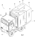
- the transport refrigeration systems 20 may include a tractor or vehicle 22, a container 24, and an engineless transportation refrigeration unit (TRU) 26.
- the container 24 may be pulled by a vehicle 22. It is understood that embodiments described herein may be applied to shipping containers that are shipped by rail, sea, air, or any other suitable container, thus the vehicle may be a truck, train, boat, airplane, helicopter, etc.
- the vehicle 22 may include an operator's compartment or cab 28 and a combustion engine 42 which is part of the powertrain or drive system of the vehicle 22.
- the vehicle 22 may be a hybrid or all electric configuration having electric motors to provide propulsive force for the vehicle.
- the TRU system 26 may be engineless.
- a small engine or the engine of the vehicle 22 may be employed to power or partially power the TRU 26.
- the container 24 may be coupled to the vehicle 22 and is thus pulled or propelled to desired destinations.
- the trailer may include a top wall 30, a bottom wall 32 opposed to and spaced from the top wall 30, two side walls 34 spaced from and opposed to one-another, and opposing front and rear walls 36, 38 with the front wall 36 being closest to the vehicle 22.
- the TRU 26 is associated with a container 24 to provide desired environmental parameters, such as, for example temperature, pressure, humidity, carbon dioxide, ethylene, ozone, light exposure, vibration exposure, and other conditions to the cargo compartment 40.
- desired environmental parameters such as, for example temperature, pressure, humidity, carbon dioxide, ethylene, ozone, light exposure, vibration exposure, and other conditions to the cargo compartment 40.
- the TRU 26 is a refrigeration system capable of providing a desired temperature and humidity range.
- Operation of the engineless TRU 26 may best be understood by starting at the compressor 58, where the suction gas (e.g., natural refrigerant, hydrofluorocarbon (HFC) R-404a, HFC R-134a... etc.) enters the compressor 58 at a suction port 84 and is compressed to a higher temperature and pressure.
- the refrigerant gas is emitted from the compressor 58 at an outlet port 85 and may then flow into tube(s) 86 of the condenser 64.
- the air flow across the condenser 64 may be facilitated by one or more fans 88 of the condenser fan assembly 66.
- the condenser fans 88 may be driven by respective condenser fan motors 90 of the fan assembly 66 that may be electric.
- the refrigerant gas within the tubes 86 condenses to a high pressure and high temperature liquid and flows to the receiver 68 that provides storage for excess liquid refrigerant during low temperature operation.
- the liquid refrigerant may pass through a sub-cooler heat exchanger 92 of the condenser 64, through the filter-dryer 70 that keeps the refrigerant clean and dry, then to the heat exchanger 72 that increases the refrigerant sub-cooling, and finally to the expansion valve 74.
- FIG. 2 also illustrates airflow through the TRU 26 and the cargo compartment 40.
- Airflow is circulated into and through and out of the cargo compartment 40 of the container 24 by means of the TRU 26.
- a return airflow 134 flows into the TRU 26 from the cargo compartment 40 through a return air intake 136, and across the evaporator 76 via the fan 96, thus conditioning the return airflow 134 to a selected or predetermined temperature.
- the conditioned return airflow 134 now referred to as supply airflow 138, is supplied into the cargo compartment 40 of the container 24 through the refrigeration unit outlet 140, which in some embodiments is located near the top wall 30 of the container 24.
- the supply airflow 138 cools the perishable goods in the cargo compartment 40 of the container 24.
- the TRU 26 can further be operated in reverse to warm the container 24 when, for example, the outside temperature is very low.
- the power management system 190 includes a DC/AC converter 194.
- the DC/AC converter 194 is configured to receive DC power on the DC bus 125 denoted in this instance 125a (e.g., second DC voltage V 2 , a second DC current I 2 from the generator power converter 165; and/or V G , I G 185; and/or DC voltage 155 from the energy storage device 152; alone or as combined) and generate three phase AC power 195 (e.g., at AC voltage V 2 , AC current I 2 a frequency f 2 ), for providing power to the TRU system 26.
- the DC/AC converter 194 includes a voltage control function, a current control function, and a frequency control function, each configured to facilitate the conversion.
- the TRU controller 82 provides command signals denoted by line 191, to the power management system 190.
- the commands are based, at least, on the power consumption requirements of the TRU 26 as discussed further herein.
- the TRU controller 82 may receive status information also depicted by line 191 regarding the DC/AC converter 194.
- the communications may be over standard communication interfaces such as CAN, RS-485, and the like.
- the communications may be wired or wireless.
- the TRU controller 82 identifies the power requirements for the TRU 26 at least partially based on the RAT.
- the TRU controller 82 conveys the power requirements to the power management system 190 and/or the generator power converter 164 to convert the first three phase AC power 163 or first DC power 163a to the second DC power 165 as necessary to satisfy the requirements of the TRU 26 and the energy storage system 150 and specifically the charging requirements of the energy storage device 152.
- the DC bus 125 and thereby, the power management system 190 may receive power from a grid power source 182 when it is available.
- the grid power source 182 is interfaced to the DC bus 125 and the power management system 190 via a grid power converter 184.
- the power management system 190 may be a stand-alone unit, or integral with the TRU 26.
- the grid power source 182 is generally conventional three phase AC power 220/480VAC at 60 or 400Hz.
- the grid power converter 184 is a conventional AC/DC converter operable to convert the three phase AC power from the grid power source 182 to a DC voltage and current.
- the DC bus 125 and power management system 190 receives power from a generator 162 directly and/or via a generator power converter 164.
- the generator 162 can be axle or hub mounted configured to recover rotational energy when the transport refrigeration system 20 is in motion and convert that rotational energy to electrical energy, such as, for example, when the axle of the vehicle 22 is rotating due to acceleration, cruising, or braking.
- the generator 162 is configured to provide a first three phase AC power 163 comprising voltage V 1 , an AC current I 1 at a given frequency f 1 denoted by reference numeral 163.
- the generator 162 may be asynchronous or synchronous.
- DC/DC converter 156 is described as bidirectional, such description is merely for the purposes of illustration. In operation, the DC/DC converter 156 may be a single integrated unit, or multiple units configured in parallel to operate in opposite directions. It is also noteworthy to appreciate that in the various embodiments described herein, numerous architectures are described based on the interconnection between the various power sources 122. More specifically, the interconnection between power sources 122, e.g., grid power source 182, generator 162 and the DC/AC converter 194 of the power management system 190 with the energy storage device 152, based on the optional application of the optional DC/DC converter 156. In the various architectures, where the energy storage device 152 is directly connected (e.g.
- that portion of the bus is termed variable as the voltage is capable of variation based on the state of charge of the energy storage device 152.
- the portions of the DC bus directly connected (e.g., 125b) to the energy storage device 152 and at the input connection to the DC/DC converter are considered variable, while the portion at the output of the DC/DC converter 156 connected to the DC bus 125, (e.g., 125a) are considered fixed and regulated.
- the battery management system 154 monitors the performance of the energy storage device 152. For example, monitoring the state of charge of the energy storage device 152, a state of health of the energy storage device 152, and a temperature of the energy storage device 152.
- Examples of the energy storage device 152 may include a battery system (e.g., a battery or bank of batteries), fuel cells, flow battery, ultracapacitors, and others devices capable of storing and outputting electric energy that may be direct current (DC).
- the energy storage device 152 may include a battery system, which may employ multiple batteries organized into battery banks.
- the battery system 150 may have a voltage potential within a range of about two-hundred volts (200V) to about six-hundred volts (600V). Generally, the higher the voltage, the greater is the sustainability of electric power which is preferred. However, with increases in the voltage, the size and weight of the battery/batteries in an energy storage device 152 increase. Increased size and weight are generally not preferred when transporting cargo. Additionally, if the energy storage device 152 is a battery, then in order to increase either voltage and/or current, the batteries need to be connected in series or parallel depending upon electrical needs.
- the energy storage device 152 may be contained within the structure 27 of the TRU 26. In an embodiment, the energy storage device 152 is located with the TRU 26, however, other configurations are possible. In another embodiment, the energy storage device 152 may be located with the container 24 such as, for example, underneath the cargo compartment 40. Likewise, the DC/DC converter 156 may be located with the container 24 such as, for example, underneath the cargo compartment 40, however, in some embodiments it may be desirable to have the DC/DC converter 156 in close proximity to the power management system 190 and/or the TRU 26 and TRU controller 82.
- the battery management system 154 and DC/DC converter 156 are operably connected to and interface with the TRU controller 82.
- the TRU controller 82 receives information regarding the status of energy storage system 150, including the energy storage device 152 to provide control inputs to the DC/DC converter 156 to monitor the energy storage device 152, as well as control charge and discharge rates for the energy storage device 152.
- the TRU controller 82 provides command signals denoted 169, and 170 to a voltage control function 166, current control function 167, respectively.
- the command signals 169, and 170 are generated by the TRU controller 82 based on the power consumption requirements of the TRU 26 as discussed further herein.
- the TRU controller 82 may receive status information as depicted by 171, 172 regarding the generator power converter 164, and generator 162 respectively.
- the generator power converter may receive control signal or provide status signals to TRU controller 82, the power management system 190, or energy storage system 150 for mode selection and diagnostic purposes.
- the communications may be over standard communication interfaces such as CAN, RS-485, and the like.
- the communications may be wired or wireless.
- the generator power converter 164, the voltage control function 166 includes a voltage regulation function and is configured to monitor the output voltage from the generator 162 and maintains a constant DC voltage out of the voltage control function 166.
- the voltage control function 166 communicates status to the TRU Controller 82.
- the current control function 167 monitors and communicates to the TRU 26 the status of current draw from the generator 162. In an embodiment, the current may be limited depending on the power demands of the TRU 26.
- a frequency converter function 168 may also monitors the frequency of the three phase power 163 produced by the generator 162 to facilitate the conversion of the three phase power 163 to the second DC power 165 as determined by the voltage control function 166 and the TRU controller 82 for supply to the power management system 190 and ultimately the TRU 26.
- the generator power converter 164 may be a stand-alone unit configured to be in close proximity to or even integral with the generator 162.
- the generator power converter 164 is an DC/DC converter and configured to receive DC power 163a (e.g., at DC voltage V 1a , DC current I 1a ), from the generator 162 and convert it to the second DC power denoted 165a comprising a second DC voltage V 2a , a second DC current I 2a .
- the second DC power 165a is transmitted from the generator power converter 164 to the power management system 190.
- the generator power converter 164 is configured to provide the second DC power 165a based of the requirements of the TRU 26 as described above.
- the power supply interface 120 may include, interfaces to various power sources 122 managed and monitored by the TRU controller 82.
- the TRU controller 82 and the power management system 190 manages and determines electrical power flows in the power supply interface 120 based upon the operational needs of the TRU 26 and the capabilities of the components in the power supply interface 120, (e.g., generator 162, converter 164, energy storage device 152, and the like.
- the TRU controller determines the status of various power sources 122, controls their operation, and directs the power to and from the various power sources 122 and the like based on various requirements of the TRU 26.
- the power flows will be transferred through different paths based on the requirements placed on the power management system 190 and particular configuration of the power supply interface 120.
- the DC bus 125 and the power management system 190 operates as a central power bus to connect various power sources 122 together to supply the power needs of the TRU 26.
- the TRU controller and power management system 190 controls switching, directing, or redirecting power to/from the five power flows as needed to satisfy the power requirements of the TRU 26.
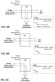
- FIGS 4A-4H each providing a simplified diagram depicting each of the various possible power flow combinations in the power supply interface 120 associated with the DC bus 125.
- FIGS. 4A-4C depict power flows for power supplied from the generator 162 and/or generator power converter 164 (e.g., second DC power).
- the power on the DC bus 125 is directed to the power management system 190 and thereby the TRU 26 and the energy storage system 150 for recharging the energy storage device 152.
- priority is given to satisfying the power requirements of the TRU 26. Any remaining power may be directed to the recharging application for the energy storage system 150.
- FIG 4B the figure depicts a second instance for power flows for power supplied from the generator 162 and/or generator power converter 164.
- the energy storage system 150 indicates that the energy storage device 152 is exhibiting a state of charge that is in excess of a selected threshold
- the power on the DC bus 125 is directed only to the power management system 190 to power only the TRU 26, (as the and the energy storage system 150 does not yet require recharging).
- FIG 4C a third power flow for power supplied from the generator 162 and/or generator power converter 164.
- the logic employed by the TRU controller 82 for directing the power to the power management system 190 addresses an instance when the TRU 26 is inoperative, and the energy storage system 150 indicates that the energy storage device 152 is exhibiting a state of charge that is less than a selected threshold (in this instance 100%, though other thresholds are possible).
- the DC power on the DC bus 125 is directed only to the energy storage system 150 for recharging the energy storage device 152.
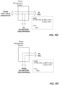
- FIGS. 4D-4F depict power flows for power supplied from the grid power source 182.
- the logic employed by the TRU controller 82 for directing the power from the grid power source 182 determines if the TRU 26 is operating and the generator 162 (or the generator power converter 164) is inoperative. If so, and the energy storage system 150 indicates that the energy storage device 152 is exhibiting a charge state that is less than a selected threshold, then power is directed from the DC bus 125 to both the power management system 190 and then the TRU system 26 and the energy storage system 150 for recharging the energy storage device 152. In an embodiment, once again, priority is given to satisfying the power requirements of the TRU system 26.
- any remaining power may be directed to the recharging application for the energy storage system 150. It should be appreciated that while particular threshold of 80% is disclosed and employed for the described embodiments, such values and description are merely illustrative. Other values and applications for the thresholds are possible.
- FIG 4E the figure depicts a second instance for power flows for power supplied from the grid power source 182 when the generator 162 is inoperative.
- the DC power on the DC bus 125 is directed only to the power management system 190 directs and to the TRU 26, (as the energy storage system 150 does not yet require recharging).
- FIG 4F a third power flow for power supplied from the grid power source 182 when the generator 162 is inoperative.
- the logic employed by the TRU controller 82 for directing the power on the DC bus 125 addresses an instance when the TRU 26 is also inoperative, and the energy storage system 150 indicates that the energy storage device 152 is exhibiting a state of charge that is less than a selected threshold (in this instance 100%, though other thresholds are possible).
- the power on the DC bus 125 is directed only to the energy storage system 150 for recharging the energy storage device 152. In an embodiment, priority is given to satisfying the power requirements of energy storage system 150.
- the energy storage system 150 indicates that the energy storage device 152 is exhibiting a charge state of greater than a selected threshold
- power from both the generator 162 (or generator power converter 164) and the energy storage system 150 is directed to DC bus 125 and then to the power management system 190 and thereby the TRU 26.
- a threshold of 10 percent is employed for the state of charge of the energy storage device 152.
- power is provided by the energy storage system 150 and thereby discharging the energy storage device 152.
- priority is given to satisfying the power requirements of the TRU 26. This embodiment may be employed under conditions where the output power of the generator 162 and/or generator power converter 164 is less that that needed to operate the TRU 26.
- this embodiment may be employed under conditions where the output power of the generator 162 and/or generator power converter 164 is less that that needed to operate the TRU 26.
- threshold of 10% is disclosed and employed for the described embodiments, such values and description are merely illustrative. Other values and applications for the thresholds are possible. For example, in some instances it may be desirable prioritize operation of the TRU 26 such that fully draining the energy storage device 152 is acceptable. Likewise, in other embodiments, it may be desirable to modify the function or curtail the operation of the TRU to avoid excessively discharging the energy storage device 152.
- the power supply interface 120 is configured such that, in selected modes of operation power is directed to the TRU 26 from the tractor or vehicle 22.
- the energy storage device 152 exhibit a SOC below a selected threshold e.g., ⁇ 10% and the generator 162/generator power converter 164 is not operable but the TRU system 26 is operable and requires power
- TRU power could be drawn from the power system of the tractor or truck. (i.e. tie into the energy storage device or generator of the tractor/truck).
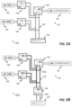
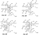
- FIG 5F depicts another simplified block diagram of the power supply interface 620 in accordance with still another embodiment as described herein.
- FIG. 5F depicts a configuration of the power supply interface 620 where the grid power supply 182 and grid power converter 184 as well as the generator 162 and the output of the generator power converter 164 are connected with the DC/DC converter 156 forming the fixed DC bus denoted once again 125c.
- DC/DC converter 156 of the energy storage system isolates the fixed DC bus 125c from the variable DC bus 125a.
- FIG 5G depicts a simplified block diagram of the power supply interface 720 in accordance with still yet another embodiment as described herein.
- FIG. 5G depicts a configuration of the power supply interface 720where the generator 162 and the output of the generator power converter 164 are connected with the energy storage device 152 on the variable DC bus 125a in a variable configuration.
- the DC/DC converter 156 of the energy storage system forming the fixed DC bus denoted once again 125c, once again DC/DC converter 156 isolates the fixed DC bus 125c from the variable DC bus 125a.
- the output of the DC/DC converter 156 of the energy storage system 150 is connected along with grid power converter 184 to fixed DC bus 125c, providing power the DC/AC converter 192 of the power management system 190 to provide power to the TRU system 26.
- the output of the DC/DC converter 156 of the energy storage system 150 is connected along with the energy storage device 152 on the variable DC bus 125a and providing power the DC/AC converter 192 of the power management system 190 to provide power to the TRU system 26.
- Embodiments can also be in the form of computer program code, for example, whether stored in a storage medium, loaded into and/or executed by a computer, or transmitted over some transmission medium, loaded into and/or executed by a computer, or transmitted over some transmission medium, such as over electrical wiring or cabling, through fiber optics, or via electromagnetic radiation, wherein, when the computer program code is loaded into an executed by a computer, the computer becomes a device for practicing the embodiments.
- the computer program code segments configure the microprocessor to create specific logic circuits.
Landscapes
- Engineering & Computer Science (AREA)
- Mechanical Engineering (AREA)
- Physics & Mathematics (AREA)
- Thermal Sciences (AREA)
- Power Engineering (AREA)
- Chemical & Material Sciences (AREA)
- Combustion & Propulsion (AREA)
- General Engineering & Computer Science (AREA)
- Transportation (AREA)
- Supply And Distribution Of Alternating Current (AREA)
Applications Claiming Priority (3)
| Application Number | Priority Date | Filing Date | Title |
|---|---|---|---|
| US201862738689P | 2018-09-28 | 2018-09-28 | |
| EP19780484.2A EP3856549B1 (de) | 2018-09-28 | 2019-09-19 | Elektrische architektur zum betrieb einer transportkühleinheit |
| PCT/US2019/051963 WO2020068556A1 (en) | 2018-09-28 | 2019-09-19 | Electrical architecture for powering transportation refrigeration unit |
Related Parent Applications (2)
| Application Number | Title | Priority Date | Filing Date |
|---|---|---|---|
| EP19780484.2A Division EP3856549B1 (de) | 2018-09-28 | 2019-09-19 | Elektrische architektur zum betrieb einer transportkühleinheit |
| EP19780484.2A Division-Into EP3856549B1 (de) | 2018-09-28 | 2019-09-19 | Elektrische architektur zum betrieb einer transportkühleinheit |
Publications (2)
| Publication Number | Publication Date |
|---|---|
| EP4477487A2 true EP4477487A2 (de) | 2024-12-18 |
| EP4477487A3 EP4477487A3 (de) | 2025-03-12 |
Family
ID=68109479
Family Applications (2)
| Application Number | Title | Priority Date | Filing Date |
|---|---|---|---|
| EP19780484.2A Active EP3856549B1 (de) | 2018-09-28 | 2019-09-19 | Elektrische architektur zum betrieb einer transportkühleinheit |
| EP24193739.0A Pending EP4477487A3 (de) | 2018-09-28 | 2019-09-19 | Elektrische architektur zur versorgung einer transportkühleinheit |
Family Applications Before (1)
| Application Number | Title | Priority Date | Filing Date |
|---|---|---|---|
| EP19780484.2A Active EP3856549B1 (de) | 2018-09-28 | 2019-09-19 | Elektrische architektur zum betrieb einer transportkühleinheit |
Country Status (4)
| Country | Link |
|---|---|
| US (1) | US12240296B2 (de) |
| EP (2) | EP3856549B1 (de) |
| CN (1) | CN112334341B (de) |
| WO (1) | WO2020068556A1 (de) |
Families Citing this family (41)
| Publication number | Priority date | Publication date | Assignee | Title |
|---|---|---|---|---|
| EP3626489A1 (de) | 2018-09-19 | 2020-03-25 | Thermo King Corporation | Verfahren und systeme zur energieverwaltung einer klimaanlage für transportfahrzeuge |
| EP3626490A1 (de) | 2018-09-19 | 2020-03-25 | Thermo King Corporation | Verfahren und systeme zur leistungs- und lastverwaltung einer klimaanlage für den transport |
| US11273684B2 (en) | 2018-09-29 | 2022-03-15 | Thermo King Corporation | Methods and systems for autonomous climate control optimization of a transport vehicle |
| US11034213B2 (en) | 2018-09-29 | 2021-06-15 | Thermo King Corporation | Methods and systems for monitoring and displaying energy use and energy cost of a transport vehicle climate control system or a fleet of transport vehicle climate control systems |
| US10875497B2 (en) | 2018-10-31 | 2020-12-29 | Thermo King Corporation | Drive off protection system and method for preventing drive off |
| US10926610B2 (en) | 2018-10-31 | 2021-02-23 | Thermo King Corporation | Methods and systems for controlling a mild hybrid system that powers a transport climate control system |
| US10870333B2 (en) | 2018-10-31 | 2020-12-22 | Thermo King Corporation | Reconfigurable utility power input with passive voltage booster |
| US11059352B2 (en) | 2018-10-31 | 2021-07-13 | Thermo King Corporation | Methods and systems for augmenting a vehicle powered transport climate control system |
| US11022451B2 (en) | 2018-11-01 | 2021-06-01 | Thermo King Corporation | Methods and systems for generation and utilization of supplemental stored energy for use in transport climate control |
| US11554638B2 (en) | 2018-12-28 | 2023-01-17 | Thermo King Llc | Methods and systems for preserving autonomous operation of a transport climate control system |
| EP3906175A1 (de) | 2018-12-31 | 2021-11-10 | Thermo King Corporation | Verfahren und systeme zur bereitstellung von prädiktiver energieverbrauchsrückkopplung zur speisung eines transportklimaregelungssystems unter verwendung externer daten |
| EP3906173B1 (de) | 2018-12-31 | 2024-05-22 | Thermo King LLC | Verfahren und systemen mit feedback eines prädiktiven abgeschätzten energieverbrauch es zur steuerung eines klimaaggregates für eine transportvorrichtung |
| US11993131B2 (en) | 2018-12-31 | 2024-05-28 | Thermo King Llc | Methods and systems for providing feedback for a transport climate control system |
| US11072321B2 (en) | 2018-12-31 | 2021-07-27 | Thermo King Corporation | Systems and methods for smart load shedding of a transport vehicle while in transit |
| US12072193B2 (en) | 2018-12-31 | 2024-08-27 | Thermo King Llc | Methods and systems for notifying and mitigating a suboptimal event occurring in a transport climate control system |
| ES2965029T3 (es) | 2019-06-28 | 2024-04-10 | Thermo King Llc | Vehículo climatizado, equipo de control climático para el transporte, método de readaptación de un vehículo y método de funcionamiento |
| ES2992855T3 (en) | 2019-09-09 | 2024-12-19 | Thermo King Llc | Prioritized power delivery for facilitating transport climate control |
| US10985511B2 (en) | 2019-09-09 | 2021-04-20 | Thermo King Corporation | Optimized power cord for transferring power to a transport climate control system |
| US11203262B2 (en) | 2019-09-09 | 2021-12-21 | Thermo King Corporation | Transport climate control system with an accessory power distribution unit for managing transport climate control loads |
| US11214118B2 (en) | 2019-09-09 | 2022-01-04 | Thermo King Corporation | Demand-side power distribution management for a plurality of transport climate control systems |
| EP3790157A1 (de) | 2019-09-09 | 2021-03-10 | Thermo King Corporation | Optimierte energieverteilung für transportklimatisierungssysteme zwischen einer oder mehreren stationen der elektrischen versorgungsanlagen |
| US11458802B2 (en) | 2019-09-09 | 2022-10-04 | Thermo King Corporation | Optimized power management for a transport climate control energy source |
| US11376922B2 (en) | 2019-09-09 | 2022-07-05 | Thermo King Corporation | Transport climate control system with a self-configuring matrix power converter |
| US11135894B2 (en) | 2019-09-09 | 2021-10-05 | Thermo King Corporation | System and method for managing power and efficiently sourcing a variable voltage for a transport climate control system |
| US11420495B2 (en) | 2019-09-09 | 2022-08-23 | Thermo King Corporation | Interface system for connecting a vehicle and a transport climate control system |
| US11489431B2 (en) | 2019-12-30 | 2022-11-01 | Thermo King Corporation | Transport climate control system power architecture |
| EP3901542B1 (de) * | 2020-04-22 | 2026-04-01 | Carrier Corporation | Spannungswandlungssystem für ein transportkühlsystem |
| WO2021257563A2 (en) * | 2020-06-15 | 2021-12-23 | Arizona Board Of Regents On Behalf Of Arizona State University | Systems, methods, and apparatus for implementing aggregable, environment-controlled mini-containers for the efficient logistics of perishable products |
| EP4063151B1 (de) | 2021-03-23 | 2024-04-24 | Carrier Corporation | Elektrische architektur zur versorgung mehrerer transportkühleinheiten |
| EP4071981B1 (de) * | 2021-04-06 | 2023-05-31 | Carrier Fire & Security EMEA BV | Stromverwaltungssystem für eine transportkühleinheit |
| EP4101695A1 (de) * | 2021-06-08 | 2022-12-14 | Carrier Corporation | Stromverwaltungssystem für eine transportkühleinheit |
| CN115885447B (zh) * | 2021-07-29 | 2024-02-02 | 宁德时代新能源科技股份有限公司 | 充放电装置、电池充电和放电的方法、以及充放电系统 |
| EP4206007A1 (de) | 2022-01-04 | 2023-07-05 | Carrier Corporation | Niederspannungs-energiesystem für eine transportkühleinheit |
| US12409709B2 (en) | 2022-01-04 | 2025-09-09 | Carrier Corporation | Medium-to-high voltage power system for a transport refrigeration unit |
| EP4234287B1 (de) * | 2022-02-28 | 2025-08-06 | Carrier Corporation | Hybridisierte brennstoffzellentransportkühleinheiten |
| US20230373416A1 (en) * | 2022-05-23 | 2023-11-23 | Carrier Corporation | Transport refrigeration energy storage system |
| US12355339B2 (en) * | 2022-07-18 | 2025-07-08 | Carrier Corporation | Hybrid power system for transport refrigeration systems |
| EP4321355A1 (de) * | 2022-08-08 | 2024-02-14 | Thermo King LLC | Gerät mit einem photovoltaischen system |
| US20250112491A1 (en) * | 2023-09-29 | 2025-04-03 | Carrier Corporation | Power system for transportation refrigeration unit and method for controlling power thereof |
| EP4613520A3 (de) * | 2024-03-05 | 2025-10-29 | Carrier Corporation | Stromversorgungsverwaltung in einer transportkühleinheit |
| EP4675881A1 (de) * | 2024-07-02 | 2026-01-07 | Carrier Corporation | Rekonfigurierbare elektrische architektur zum effizienten betrieb einer anhängerkühleinheit |
Family Cites Families (47)
| Publication number | Priority date | Publication date | Assignee | Title |
|---|---|---|---|---|
| JPH0490472A (ja) * | 1990-08-02 | 1992-03-24 | Hino Motors Ltd | 冷凍車両用冷却装置 |
| KR0168094B1 (ko) | 1993-10-19 | 1999-01-15 | 김광호 | 공기조화기의 운전제어장치 및 그 제어방법 |
| US5568023A (en) * | 1994-05-18 | 1996-10-22 | Grayer; William | Electric power train control |
| JP4426737B2 (ja) | 2000-06-28 | 2010-03-03 | 東芝キヤリア株式会社 | 車両用冷凍装置 |
| AU2001278046A1 (en) | 2000-07-28 | 2002-02-13 | International Power Systems, Inc. | Dc to dc converter and power management system |
| JP2002081825A (ja) | 2000-09-01 | 2002-03-22 | Denso Corp | 冷凍冷蔵庫 |
| US7207183B2 (en) | 2004-04-12 | 2007-04-24 | York International Corp. | System and method for capacity control in a multiple compressor chiller system |
| US20070151272A1 (en) | 2006-01-03 | 2007-07-05 | York International Corporation | Electronic control transformer using DC link voltage |
| US7573145B2 (en) | 2006-11-16 | 2009-08-11 | Cummins Power Generation Ip, Inc. | Electric power generation system controlled to reduce perception of operational changes |
| EP1935712A1 (de) * | 2006-12-22 | 2008-06-25 | Nederlandse Organisatie voor Toegepast-Natuuurwetenschappelijk Onderzoek TNO | Fahrzeugsystem und -verfahren |
| WO2008094148A1 (en) | 2007-01-31 | 2008-08-07 | Carrier Corporation | Integrated multiple power conversion system for transport refrigeration units |
| US20090045782A1 (en) | 2007-08-16 | 2009-02-19 | General Electric Company | Power conversion system |
| JP4939355B2 (ja) | 2007-09-28 | 2012-05-23 | 三菱重工業株式会社 | 車載空気調和機用インバータシステム |
| US8360180B2 (en) | 2007-12-31 | 2013-01-29 | Caterpillar Inc. | System for controlling a hybrid energy system |
| ES2699628T3 (es) * | 2008-07-25 | 2019-02-12 | Carrier Corp | Protección continua de la envoltura de un compresor |
| US8324846B2 (en) | 2008-09-15 | 2012-12-04 | Caterpillar Inc. | Electric drive retarding system and method |
| US8008808B2 (en) | 2009-01-16 | 2011-08-30 | Zbb Energy Corporation | Method and apparatus for controlling a hybrid power system |
| US8115334B2 (en) | 2009-02-18 | 2012-02-14 | General Electric Company | Electrically driven power take-off system and method of manufacturing same |
| US9689598B2 (en) | 2009-03-10 | 2017-06-27 | Thermo King Corporation | Systems and methods of powering a refrigeration unit of a hybrid vehicle |
| CN102803865A (zh) * | 2010-03-08 | 2012-11-28 | 开利公司 | 运输制冷系统中的能力和压力控制 |
| US8590330B2 (en) | 2010-06-03 | 2013-11-26 | Thermo King Corporation | Electric transport refrigeration unit with temperature-based diesel operation |
| US20130121844A1 (en) | 2010-06-17 | 2013-05-16 | Dresser-Rand Company | Variable Speed High Efficiency Gas Compressor System |
| WO2012138500A1 (en) | 2011-04-04 | 2012-10-11 | Carrier Corporation | Transport refrigeration system and method for operating |
| EP2694304B1 (de) | 2011-04-04 | 2018-05-02 | Carrier Corporation | Halbelektrisches mobiles gekühltes system |
| CN203965988U (zh) | 2011-10-25 | 2014-11-26 | K·卡梅伦 | 电力调节器电路藉由非线性发电机以最大化功率的输出 |
| US9562715B2 (en) | 2012-03-21 | 2017-02-07 | Thermo King Corporation | Power regulation system for a mobile environment-controlled unit and method of controlling the same |
| CN104661842A (zh) | 2012-09-20 | 2015-05-27 | 冷王公司 | 电动运输制冷系统 |
| US9389007B1 (en) * | 2013-01-09 | 2016-07-12 | New West Technologies, LLC | Transportation refrigeration system with integrated power generation and energy storage |
| JP6082886B2 (ja) | 2013-02-22 | 2017-02-22 | 株式会社高砂製作所 | 電力調整装置及び電力調整方法 |
| US9898018B2 (en) | 2013-03-14 | 2018-02-20 | Arda Power Inc. | Power clipping method and system |
| US9705324B2 (en) | 2013-12-03 | 2017-07-11 | Abb Schweiz Ag | Converter system for AC power sources |
| WO2015112531A1 (en) | 2014-01-27 | 2015-07-30 | Netronex, Inc. | Ac motor drive powered concurrently by ac grid and dc solar array |
| US10046641B2 (en) | 2014-03-19 | 2018-08-14 | Motivo Engineering LLC | Mobile power conversion and distribution system |
| KR101451787B1 (ko) | 2014-06-19 | 2014-10-21 | 국방과학연구소 | 전기추진 차량의 고효율 전력변환 제어방법 |
| WO2016036832A1 (en) | 2014-09-03 | 2016-03-10 | Kettering University | Wireless power transfer system |
| US9948108B2 (en) | 2014-09-30 | 2018-04-17 | Sparq Systems Inc. | DC-bus controller for an inverter |
| CA2865612C (en) | 2014-09-30 | 2021-01-26 | Queen's University At Kingston | Dc-bus controller for an inverter |
| US9701175B2 (en) | 2015-04-14 | 2017-07-11 | Ford Global Technologies, Llc | Hybrid vehicle split exhaust system with exhaust driven electric machine and A/C compressor |
| US10283966B2 (en) | 2015-07-31 | 2019-05-07 | Bluvert Technologies Ltd. | System and methods for power generation |
| CN105751851B (zh) | 2016-02-19 | 2018-11-30 | 成都雅骏新能源汽车科技股份有限公司 | 一种冷藏车电气控制系统 |
| KR101836230B1 (ko) | 2016-04-14 | 2018-03-09 | 금오공과대학교 산학협력단 | 가변 전압 dc 마이크로그리드 시스템 및 이의 운전 방법 |
| US10300831B2 (en) * | 2016-06-01 | 2019-05-28 | Cummins Inc. | Hybrid reefer systems |
| US9969273B2 (en) | 2016-07-12 | 2018-05-15 | Hamilton Sundstrand Corporation | Integrated modular electric power system for a vehicle |
| GB2554954B (en) | 2016-10-17 | 2018-11-21 | Zhong Qingchang | Operating doubly-fed induction generators as virtual synchronous generators |
| GB2557283A (en) | 2016-12-04 | 2018-06-20 | Entrust Microgrid Llp | Microgrid for Use in a Built Environment and Associated Apparatuses and Methods of Operating the Same |
| CN110431027B (zh) | 2017-01-20 | 2023-05-09 | 开利公司 | 运输制冷单元(tru)直流(dc)架构 |
| EP3634792B1 (de) | 2017-06-07 | 2024-10-23 | Carrier Corporation | Hybrides leistungsumwandlungssystem für ein kühltransportfahrzeug und verfahren |
-
2019
- 2019-09-19 EP EP19780484.2A patent/EP3856549B1/de active Active
- 2019-09-19 CN CN201980042624.0A patent/CN112334341B/zh active Active
- 2019-09-19 EP EP24193739.0A patent/EP4477487A3/de active Pending
- 2019-09-19 WO PCT/US2019/051963 patent/WO2020068556A1/en not_active Ceased
- 2019-09-19 US US17/252,170 patent/US12240296B2/en active Active
Also Published As
| Publication number | Publication date |
|---|---|
| WO2020068556A1 (en) | 2020-04-02 |
| CN112334341B (zh) | 2025-02-28 |
| US20210252947A1 (en) | 2021-08-19 |
| EP4477487A3 (de) | 2025-03-12 |
| EP3856549B1 (de) | 2024-09-11 |
| CN112334341A (zh) | 2021-02-05 |
| EP3856549A1 (de) | 2021-08-04 |
| US12240296B2 (en) | 2025-03-04 |
Similar Documents
| Publication | Publication Date | Title |
|---|---|---|
| US12240296B2 (en) | Electrical architecture for powering transportation refrigeration unit | |
| EP3856550B1 (de) | Transportkühleinheit mit externer wechselstromgeneratorstromquelle | |
| EP4219202B1 (de) | Transportkühleinheit mit wechselstromgenerator zur aufladung der energiespeichervorrichtung einer kraftmaschine | |
| US11884335B2 (en) | Transportation refrigeration unit with energy storage system and external DC power source | |
| EP3856545B1 (de) | Transportkühleinheit mit gleichstromgenerator zur aufladung der energiespeichervorrichtung einer kraftmaschine | |
| EP4212369B1 (de) | Transportkühleinheit mit externer gleichstromgeneratorstromquelle | |
| US11951800B2 (en) | Simultaneous charge/discharge of battery for transportation refrigeration usage | |
| US20250313056A1 (en) | Transportation refrigeration unit with ac generator charging of prime mover energy storage device |
Legal Events
| Date | Code | Title | Description |
|---|---|---|---|
| PUAI | Public reference made under article 153(3) epc to a published international application that has entered the european phase |
Free format text: ORIGINAL CODE: 0009012 |
|
| STAA | Information on the status of an ep patent application or granted ep patent |
Free format text: STATUS: THE APPLICATION HAS BEEN PUBLISHED |
|
| AC | Divisional application: reference to earlier application |
Ref document number: 3856549 Country of ref document: EP Kind code of ref document: P |
|
| AK | Designated contracting states |
Kind code of ref document: A2 Designated state(s): AL AT BE BG CH CY CZ DE DK EE ES FI FR GB GR HR HU IE IS IT LI LT LU LV MC MK MT NL NO PL PT RO RS SE SI SK SM TR |
|
| REG | Reference to a national code |
Ref country code: DE Ref legal event code: R079 Free format text: PREVIOUS MAIN CLASS: B60W0030180000 Ipc: B60H0001000000 |
|
| PUAL | Search report despatched |
Free format text: ORIGINAL CODE: 0009013 |
|
| AK | Designated contracting states |
Kind code of ref document: A3 Designated state(s): AL AT BE BG CH CY CZ DE DK EE ES FI FR GB GR HR HU IE IS IT LI LT LU LV MC MK MT NL NO PL PT RO RS SE SI SK SM TR |
|
| RIC1 | Information provided on ipc code assigned before grant |
Ipc: B60W 30/18 20120101ALI20250203BHEP Ipc: B60K 25/08 20060101ALI20250203BHEP Ipc: H02J 7/14 20060101ALI20250203BHEP Ipc: F25D 11/00 20060101ALI20250203BHEP Ipc: B60H 1/32 20060101ALI20250203BHEP Ipc: B60H 1/00 20060101AFI20250203BHEP |
|
| STAA | Information on the status of an ep patent application or granted ep patent |
Free format text: STATUS: REQUEST FOR EXAMINATION WAS MADE |
|
| 17P | Request for examination filed |
Effective date: 20250909 |