EP4477333A1 - Stahlrohr, stahlrohrgruppe, rohrleitung und verfahren zur herstellung eines stahlrohrs - Google Patents
Stahlrohr, stahlrohrgruppe, rohrleitung und verfahren zur herstellung eines stahlrohrs Download PDFInfo
- Publication number
- EP4477333A1 EP4477333A1 EP23749680.7A EP23749680A EP4477333A1 EP 4477333 A1 EP4477333 A1 EP 4477333A1 EP 23749680 A EP23749680 A EP 23749680A EP 4477333 A1 EP4477333 A1 EP 4477333A1
- Authority
- EP
- European Patent Office
- Prior art keywords
- yield strength
- steel pipe
- steel pipes
- steel
- pipe
- Prior art date
- Legal status (The legal status is an assumption and is not a legal conclusion. Google has not performed a legal analysis and makes no representation as to the accuracy of the status listed.)
- Pending
Links
Images




Classifications
-
- B—PERFORMING OPERATIONS; TRANSPORTING
- B21—MECHANICAL METAL-WORKING WITHOUT ESSENTIALLY REMOVING MATERIAL; PUNCHING METAL
- B21C—MANUFACTURE OF METAL SHEETS, WIRE, RODS, TUBES, PROFILES OR LIKE SEMI-MANUFACTURED PRODUCTS OTHERWISE THAN BY ROLLING; AUXILIARY OPERATIONS USED IN CONNECTION WITH METAL-WORKING WITHOUT ESSENTIALLY REMOVING MATERIAL
- B21C37/00—Manufacture of metal sheets, rods, wire, tubes, profiles or like semi-manufactured products, not otherwise provided for; Manufacture of tubes of special shape
- B21C37/06—Manufacture of metal sheets, rods, wire, tubes, profiles or like semi-manufactured products, not otherwise provided for; Manufacture of tubes of special shape of tubes or metal hoses; Combined procedures for making tubes, e.g. for making multi-wall tubes
- B21C37/08—Making tubes with welded or soldered seams
-
- E—FIXED CONSTRUCTIONS
- E21—EARTH OR ROCK DRILLING; MINING
- E21B—EARTH OR ROCK DRILLING; OBTAINING OIL, GAS, WATER, SOLUBLE OR MELTABLE MATERIALS OR A SLURRY OF MINERALS FROM WELLS
- E21B43/00—Methods or apparatus for obtaining oil, gas, water, soluble or meltable materials or a slurry of minerals from wells
-
- B—PERFORMING OPERATIONS; TRANSPORTING
- B21—MECHANICAL METAL-WORKING WITHOUT ESSENTIALLY REMOVING MATERIAL; PUNCHING METAL
- B21C—MANUFACTURE OF METAL SHEETS, WIRE, RODS, TUBES, PROFILES OR LIKE SEMI-MANUFACTURED PRODUCTS OTHERWISE THAN BY ROLLING; AUXILIARY OPERATIONS USED IN CONNECTION WITH METAL-WORKING WITHOUT ESSENTIALLY REMOVING MATERIAL
- B21C51/00—Measuring, gauging, indicating, counting, or marking devices specially adapted for use in the production or manipulation of material in accordance with subclasses B21B - B21F
- B21C51/005—Marking devices
-
- F—MECHANICAL ENGINEERING; LIGHTING; HEATING; WEAPONS; BLASTING
- F16—ENGINEERING ELEMENTS AND UNITS; GENERAL MEASURES FOR PRODUCING AND MAINTAINING EFFECTIVE FUNCTIONING OF MACHINES OR INSTALLATIONS; THERMAL INSULATION IN GENERAL
- F16L—PIPES; JOINTS OR FITTINGS FOR PIPES; SUPPORTS FOR PIPES, CABLES OR PROTECTIVE TUBING; MEANS FOR THERMAL INSULATION IN GENERAL
- F16L9/00—Rigid pipes
- F16L9/02—Rigid pipes of metal
-
- G—PHYSICS
- G06—COMPUTING OR CALCULATING; COUNTING
- G06Q—INFORMATION AND COMMUNICATION TECHNOLOGY [ICT] SPECIALLY ADAPTED FOR ADMINISTRATIVE, COMMERCIAL, FINANCIAL, MANAGERIAL OR SUPERVISORY PURPOSES; SYSTEMS OR METHODS SPECIALLY ADAPTED FOR ADMINISTRATIVE, COMMERCIAL, FINANCIAL, MANAGERIAL OR SUPERVISORY PURPOSES, NOT OTHERWISE PROVIDED FOR
- G06Q10/00—Administration; Management
- G06Q10/04—Forecasting or optimisation specially adapted for administrative or management purposes, e.g. linear programming or "cutting stock problem"
-
- G—PHYSICS
- G06—COMPUTING OR CALCULATING; COUNTING
- G06Q—INFORMATION AND COMMUNICATION TECHNOLOGY [ICT] SPECIALLY ADAPTED FOR ADMINISTRATIVE, COMMERCIAL, FINANCIAL, MANAGERIAL OR SUPERVISORY PURPOSES; SYSTEMS OR METHODS SPECIALLY ADAPTED FOR ADMINISTRATIVE, COMMERCIAL, FINANCIAL, MANAGERIAL OR SUPERVISORY PURPOSES, NOT OTHERWISE PROVIDED FOR
- G06Q10/00—Administration; Management
- G06Q10/06—Resources, workflows, human or project management; Enterprise or organisation planning; Enterprise or organisation modelling
- G06Q10/063—Operations research, analysis or management
- G06Q10/0639—Performance analysis of employees; Performance analysis of enterprise or organisation operations
- G06Q10/06395—Quality analysis or management
-
- G—PHYSICS
- G06—COMPUTING OR CALCULATING; COUNTING
- G06Q—INFORMATION AND COMMUNICATION TECHNOLOGY [ICT] SPECIALLY ADAPTED FOR ADMINISTRATIVE, COMMERCIAL, FINANCIAL, MANAGERIAL OR SUPERVISORY PURPOSES; SYSTEMS OR METHODS SPECIALLY ADAPTED FOR ADMINISTRATIVE, COMMERCIAL, FINANCIAL, MANAGERIAL OR SUPERVISORY PURPOSES, NOT OTHERWISE PROVIDED FOR
- G06Q50/00—Information and communication technology [ICT] specially adapted for implementation of business processes of specific business sectors, e.g. utilities or tourism
- G06Q50/04—Manufacturing
-
- G—PHYSICS
- G06—COMPUTING OR CALCULATING; COUNTING
- G06Q—INFORMATION AND COMMUNICATION TECHNOLOGY [ICT] SPECIALLY ADAPTED FOR ADMINISTRATIVE, COMMERCIAL, FINANCIAL, MANAGERIAL OR SUPERVISORY PURPOSES; SYSTEMS OR METHODS SPECIALLY ADAPTED FOR ADMINISTRATIVE, COMMERCIAL, FINANCIAL, MANAGERIAL OR SUPERVISORY PURPOSES, NOT OTHERWISE PROVIDED FOR
- G06Q50/00—Information and communication technology [ICT] specially adapted for implementation of business processes of specific business sectors, e.g. utilities or tourism
- G06Q50/06—Energy or water supply
-
- G—PHYSICS
- G06—COMPUTING OR CALCULATING; COUNTING
- G06Q—INFORMATION AND COMMUNICATION TECHNOLOGY [ICT] SPECIALLY ADAPTED FOR ADMINISTRATIVE, COMMERCIAL, FINANCIAL, MANAGERIAL OR SUPERVISORY PURPOSES; SYSTEMS OR METHODS SPECIALLY ADAPTED FOR ADMINISTRATIVE, COMMERCIAL, FINANCIAL, MANAGERIAL OR SUPERVISORY PURPOSES, NOT OTHERWISE PROVIDED FOR
- G06Q50/00—Information and communication technology [ICT] specially adapted for implementation of business processes of specific business sectors, e.g. utilities or tourism
- G06Q50/08—Construction
-
- F—MECHANICAL ENGINEERING; LIGHTING; HEATING; WEAPONS; BLASTING
- F16—ENGINEERING ELEMENTS AND UNITS; GENERAL MEASURES FOR PRODUCING AND MAINTAINING EFFECTIVE FUNCTIONING OF MACHINES OR INSTALLATIONS; THERMAL INSULATION IN GENERAL
- F16L—PIPES; JOINTS OR FITTINGS FOR PIPES; SUPPORTS FOR PIPES, CABLES OR PROTECTIVE TUBING; MEANS FOR THERMAL INSULATION IN GENERAL
- F16L2201/00—Special arrangements for pipe couplings
- F16L2201/60—Identification or marking
Definitions
- the present invention relates to a steel pipe, a steel pipe group, a pipeline, and a steel pipe manufacturing method.
- Pipelines of this type may be laid on the sea floor or on land.
- R-lay Reel lay
- pipe end surfaces of a plurality of steel pipes are joined to each other by circumferential welding in a base called a land spool base.
- the steel pipes are linearly connected to each other to form a part of the pipeline.
- the length of one steel pipe is about 12 m.
- nearly 100 steel pipes are joined, and the total length exceeds 1 km.
- the joined steel pipe is wound around a drum with a diameter of about 15 m for transportation.
- circumferential welds are arranged at intervals of about 12 m along the longitudinal direction (circumferential direction of the drum).
- the drum around which the joined steel pipe is wound is conveyed to a ship for laying pipelines, called laybarge.
- laybarge On the sea, the steel pipe wound around the drum on the ship is unwound from the drum and submerged in the sea. This results in the pipeline being laid on the sea floor.
- the pipeline is wound on a drum on land and unwound and straightened from the drum on the sea. Also, in the event of trouble, the pipeline is rewound on the drum on the sea and then unwound from the drum again. For this reason, in the R-lay method, it is required that buckling and fracture do not occur in the pipeline even when winding and unwinding of the pipeline around the drum are performed up to five times.
- tensile and compressive plastic strains in the axial direction due to bending occur on the surface (outer circumferential surface) of the steel pipe. The magnitude of plastic strain occurred at this time is proportional to the pipe diameter (outer diameter). In a steel pipe having a practical pipe diameter of 150 mm to 500 mm, tensile and compressive strains of 1% to 3% are repeatedly applied to the steel pipe.
- tensile strain and compressive strain may be also similarly applied to a pipeline laid on land.
- a pipeline laid on land is a long-range gas pipeline laid in a discontinuous permafrost zone or in a landslide area.
- tensile strain and compressive strain of about 2% are repeatedly applied to the steel pipe along the axial direction.
- Patent Document 1 discloses a pipeline and a manufacturing method thereof. Specifically, a pipeline having a plurality of welds in which end portions of a plurality of steel pipes are joined by welding is disclosed. Then, a difference between the yield strength of one steel pipe and the yield strength of the other steel pipe welded to each other and a yield ratio that is a ratio of the yield strength to a tensile strength of a steel pipe with a lower yield strength among the one steel pipe and the other steel pipe are controlled so as to satisfy a predetermined mathematical formula. According to this pipeline and the manufacturing method thereof, it is described that a pipeline that sufficiently exhibits deformation characteristics of a steel pipe can be provided.
- Patent Document 2 discloses a steel pipe for a reel method in which a plurality of electric resistance welded steel pipes are joined to each other in the axial direction via circumferential welds.
- setting the seam position of the electric resistance welded steel pipe to the 0 o'clock position of the pipe cross section when the pipe cross section of the electric resistance welded steel pipe is equally divided into 12 portions around the pipe axis, and the portions are sequentially set to from the 0 o'clock to 11 o'clock positions of the pipe cross section in the clockwise direction, a range from the 2 o'clock position of the pipe cross section to the 4 o'clock position of the pipe cross section or a range from the 8 o'clock position of the pipe cross section to the 10 o'clock position of the pipe cross section of one adjacent electric resistance welded steel pipe is relatively joined to the 0 o'clock position of the pipe cross section of the other adjacent electric resistance welded steel pipe.
- Patent Document 2 describes that, by relatively shifting the seam positions of the respective electric resistance welded steel pipes adjacent to each other and joining the respective electric resistance welded steel pipes to each other as described above, even if the 0 o'clock position of the pipe cross section (or the 6 o'clock position of the pipe cross section) when the long steel pipe is wound around a reel is positioned on the inner peripheral side or the outer peripheral side when winding around the reel, the axial strain occurred is reduced, and local buckling and fracture are less likely to occur.
- Non-Patent Document 1 describes that buckling in the vicinity of a circumferential weld can be prevented by suppressing a yield strength difference between steel pipes to be joined in a pipeline to which tensile and compressive plastic strains in the axial direction are repeatedly applied.
- Non-Patent Document 1 Eiji Tsuru and 4 others, "Reeling Capability of Non-Heat-Treated ERW Line Pipes in R-lay", 2013, 1SOPE-1-13-548
- Patent Document 2 focuses on local buckling and fracture occurring on the inner peripheral side and the outer peripheral side of the steel pipe wound around the reel, but does not prevent buckling in the vicinity of the circumferential weld.
- Non-Patent Document 1 discloses that the yield strength difference between the steel pipes to be joined is suppressed, but is the same as Patent Document 1 from the viewpoint that it is difficult to measure the yield strength information of all the steel pipes.
- the yield strength As can be seen from the related art, in order to suppress the yield strength difference between the steel pipes to be joined, information on the yield strength of all the connected steel pipes is required. Normally, as the value of the yield strength, a representative value for each lot (for example, for each identical manufacturing unit) measured by a material test is used. That is, one yield strength value is assigned as a representative value to a large number of steel pipes.
- this yield strength value is only a representative value of one lot, the yield strength value may be different from the actual yield strength value individually possessed by each steel pipe.
- a steel pipe having a length of, for example, 12 m + 0.5 m is prepared. Then, a portion with a length of about 0.5 m from the pipe end of the steel pipe is cut off and used as a test piece.
- This test piece corresponds to about 4% of the total length 12 m of the steel pipe, but is used only for measuring the yield strength, and is not used as an actual product.
- the cut test piece is pre-processed into a state suitable for actual measurement by performing machining such as lathe machining or milling.
- the measured value of the yield strength is obtained by performing a tensile test.
- the operation period required for the whole process from the taking out of the test piece to the actual measurement described above is about 20 days, it is not realistic to perform this on all of a large number of steel pipes.
- a yield loss of 4% occurs from each of all the steel pipes, it is difficult to perform the test in terms of cost. Specifically describing the cost in the case of performing a tensile test of one steel pipe, first, 5000 yen is spent for gas cutting, 5000 yen is spent for the test piece processing, and 5000 yen is spent for the tensile test.
- a test period of two weeks is required. Naturally, the test cost and the test period increase in proportion to the number of steel pipes, and thus it is not easy to perform the test on all the steel pipes.
- an object of the present invention is to provide a steel pipe and a steel pipe group in which yield strength information necessary for realizing the final purpose is individually provided, simply and with good yield.
- Another object of the present invention is to provide a pipeline manufactured by this steel pipe group.
- an object of the present invention is to provide a steel pipe manufacturing method for obtaining a steel pipe to which yield strength information is individually provided, simply and with good yield.
- the present invention adopts the following aspects.
- the yield strength information is a numerical value display of the yield strength
- steel pipes with the same or similar numerical value display are selected and joined.
- the yield strength information is a section display indicating a section to which the numerical value of the yield strength corresponds
- steel pipes with the same or similar numerical values of the yield strength associated with this section are selected and joined.
- the yield strength information is a color display color-coded for each yield strength
- steel pipes with the same or similar numerical values of the yield strength associated with this color-coding (steel pipes with the same color display or similar color display) are selected and joined.
- the yield strength information is a product number display associated with the numerical value of the yield strength
- steel pipes with the same or similar numerical values of the yield strength associated with the product number display are selected and joined.
- the steel pipe and the steel pipe group when a long structure such as a pipeline is obtained by connecting a plurality of steel pipes, the occurrence of buckling in the vicinity of the circumferential weld between the steel pipes can be suppressed.
- yield strength information based on the measurement result obtained by applying the instrumented indentation test to the machined pipe end surface is provided, the steel pipe and the steel pipe group to which the yield strength are provided simply and with good yield.
- the steel pipe manufacturing method when a long structure such as a pipeline is obtained by connecting a plurality of steel pipes, it is possible to manufacture a steel pipe individually provided with yield strength information necessary for suppressing the occurrence of buckling in the vicinity of the circumferential weld between the steel pipes.
- the yield strength information is provided to the steel pipe based on the measurement result obtained by applying the instrumented indentation test to the machined pipe end surface, it is possible to manufacture a steel pipe to which the yield strength is provided simply and with good yield.
- the present inventor has extensively studied, and has focused on an instrumented indentation test as a method for measuring the yield strength of a steel pipe without lowering the yield. Therefore, the present inventor verified the validity of the yield strength calculated based on the load-displacement characteristic measured on the machined pipe end surface of the steel pipe using the instrumented indentation test. Specifically, the yield strength calculated from the result of the instrumented indentation test was compared with the yield strength measured by actually performing a tensile test. A method of measuring and calculating the yield strength using the instrumented indentation test will be described later.
- the steel pipe A was an ERW steel pipe (Electric Resistance Welded steel pipe) subjected to heat treatment after forming.
- the steel pipe A had an outer diameter of 323.9 mm and a wall thickness of 14.3 mm.
- the steel pipe B was an ERW steel pipe as formed.
- the steel pipe B had an outer diameter of 457.2 mm and a wall thickness of 20.3 mm.
- the steel pipe C was an UO steel pipe as formed.
- the steel pipe C had an outer diameter of 508 mm and a wall thickness of 22.2 mm.
- the steel pipe D was an UO steel pipe subjected to an ageing treatment after forming. As with the steel pipe C, the steel pipe D had an outer diameter of 508 mm and a wall thickness of 22.2 mm.
- the ageing treatment applied to the steel pipe D is for coating the surface of the steel pipe for improving corrosion resistance.
- the yield strength of each of the steel pipes A to D was within a range of 400 MPa to 450 MPa.
- the pipe end surface was machined and flattened on the assumption that the steel pipes were joined by circumferential welding.
- An instrumented indentation test was performed on the pipe end surface (machined surface) of each of the steel pipes A to D.
- the instrumented indentation test when the wall thickness of the steel pipe was t, using the position of the outer circumferential surface of the steel pipe in the pipe end surface as a reference in the thickness direction, an indentation indenter was pressed into at least one of the positions where the distance from the outer circumferential surface toward the central axis was t/4, t/2, and 3t/4, and the yield strength was measured.
- a round bar tensile test piece with a diameter of 3 mm was collected from the vicinity of the position where the indentation indenter was pressed among the pipe end surfaces of the steel pipes A to D.
- a full-thickness tensile test is intended to collect an average value of the full thickness, and is specifically performed in a shipping test or the like.
- test pieces were collected from one position or two or more positions in the circumferential direction of pipe end surfaces of 10 different steel pipes.
- FIGS. 1 to 3 are graphs showing verification results of the steel pipe A.
- FIG. 1 shows a comparison between a stress-strain curve (hereinafter, it is also referred to as an SS curve.) calculated using an instrumented indentation test and an SS curve measured by performing a round bar tensile test on the steel pipe A.
- the horizontal axis represents strain and the vertical axis represents stress.
- the stress calculation result by the instrumented indentation test (vertical axis) was in good agreement with the stress measurement result by the round bar tensile test (vertical axis).
- FIG. 2 shows a relationship between yield strength calculated using an instrumented indentation test and yield strength measured by performing a round bar tensile test on the steel pipe A.
- FIG. 3 shows a relationship between the yield strength calculated using an instrumented indentation test and yield strength measured by performing a full-thickness tensile test. That is, it is a comparison between the weighted average value of the results of the instrumented indentation test at each position of t/4, t/2, and 3t/4 and the value in the full-thickness tensile test.
- both the yield strength measured by the round bar tensile test and the yield strength measured by the full-thickness tensile test showed a positive correlation with the yield strength calculated using the instrumented indentation test.
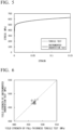
- FIG. 4 is a graph showing a verification result of the steel pipe B.
- FIG. 4 shows a relationship between yield strength calculated using an instrumented indentation test and yield strength measured by performing a round bar tensile test on the steel pipe B.
- FIGS. 5 and 6 are graphs showing verification results of the steel pipe C.
- FIG. 5 shows an SS curve calculated using an instrumented indentation test and an SS curve measured by performing a full-thickness tensile test.
- FIG. 6 shows a relationship between yield strength calculated using an instrumented indentation test and yield strength measured by performing a full-thickness tensile test on the steel pipe C. That is, it is a comparison between the weighted average value of the results of the instrumented indentation test at each position of t/4, t/2, and 3t/4 and the value in the full-thickness tensile test.
- the yield strength when no yield elongation was observed in the stress-strain curve as shown in FIG. 5 was determined as 0.2% offset yield strength.
- FIG. 7 is a graph showing a verification result of the steel pipe D.
- FIG. 7 shows a relationship between yield strength calculated using an instrumented indentation test and yield strength measured by performing a full-thickness tensile test on the steel pipe D. That is, it is a comparison between the weighted average value of the results of the instrumented indentation test at each position of t/4, t/2, and 3t/4 and the value in the full-thickness test.
- the shape of the SS curve changes and the yield strength increases as compared with the case where the ageing treatment is not performed (for example, the steel pipe C).
- the yield strength measured by performing the full-thickness tensile test shows a positive correlation with the yield strength calculated using the instrumented indentation test.
- the instrumented indentation test when the instrumented indentation test is performed on the steel pipe to be subjected to the ageing treatment, the instrumented indentation test may be performed before the ageing treatment or the instrumented indentation test may be performed after the ageing treatment as long as whether the test is performed before or after the ageing treatment is unified.
- the steel pipe manufacturing method includes a preparation step, a measurement step, an acquisition step, and a display step.
- the acquisition step may be referred to as a calculation step.
- a steel pipe having a machined flat pipe end surface is prepared.
- a load-displacement characteristic is measured on the pipe end surface of the steel pipe using an instrumented indentation test.
- the yield strength is calculated based on the load-displacement characteristic measured in the measurement step.
- information on the yield strength (hereinafter referred to as yield strength information) calculated in the calculation step is displayed on at least one of the outer circumferential surface and the inner circumferential surface of the steel pipe.
- the load-displacement characteristic is measured using the instrumented indentation test on the pipe end surface of the steel pipe, and the yield strength of each steel pipe is calculated in the calculation step based on the load-displacement characteristic. As described above, the value of the yield strength almost matches the value of the yield strength actually measured in the tensile test.
- the yield strength information calculated in the calculation step is displayed on at least one of the outer circumferential surface and the inner circumferential surface of the steel pipe.
- the operator can select a combination of steel pipes in which the yield strength difference between the steel pipes to be joined is small by confirming the displayed yield strength information.
- the steel pipes are connected to each other by welding to manufacture a pipeline, occurrence of buckling in the vicinity of the circumferential weld between the steel pipes can be suppressed.
- the steel pipe manufacturing method of the first embodiment it is possible to manufacture a steel pipe suitable for manufacturing a pipeline capable of suppressing occurrence of buckling in the vicinity of the circumferential weld between the steel pipes, simply and with good yield.
- the information displayed in the display step is the value itself of the yield strength calculated in the calculation step.
- the rest are the same as those of the first embodiment, and thus the overlapping description thereof will be omitted here.
- the value itself of the yield strength calculated in the calculation step is written on at least one of the outer circumferential surface and the inner circumferential surface of the steel pipe. Therefore, when joining the steel pipes, the operator can select a combination of steel pipes in which the yield strength difference is smaller by confirming the numerical value of the written yield strength. Therefore, appropriate steel pipes can be selected with a specific numerical value.
- the information displayed in the display step is a sign corresponding to the yield strength level including the value of the yield strength calculated in the calculation step.
- the rest are the same as those of the first embodiment, and thus the overlapping description thereof will be omitted here.
- the sign corresponding to the yield strength level including the value of the yield strength calculated in the calculation step is displayed on at least one of the outer circumferential surface and the inner circumferential surface of the steel pipe.
- the sign indicates the level of yield strength divided for each predetermined range.
- the steel pipe according to the present embodiment includes a pipe end surface, an outer circumferential surface, and an inner circumferential surface.
- the pipe end surface is machined flat.
- Yield strength information is displayed on at least one of the outer circumferential surface and the inner circumferential surface.
- the yield strength is calculated based on the load-displacement characteristic measured on the pipe end surface using an instrumented indentation test. The rest are the same as those of the first embodiment, and thus the overlapping description thereof will be omitted here.
- the yield strength information of the steel pipe is displayed on at least one of the outer circumferential surface and the inner circumferential surface of the steel pipe.
- the yield strength information relates to the yield strength obtained by the instrumented indentation test.
- the operator can select steel pipes to be joined so that the yield strength difference between the steel pipes is small by confirming the displayed information.
- the steel pipe of the fourth embodiment is suitable for manufacturing a pipeline capable of suppressing occurrence of buckling in the vicinity of the circumferential weld between the steel pipes.
- the pipeline according to the present embodiment includes the plurality of steel pipes according to the fourth embodiment connected to each other by welding. With respect to the yield strength information displayed on each steel pipe, a difference in yield strength between the steel pipes connected to each other is within a predetermined range. According to the pipeline of the fifth embodiment, since the difference in yield strength between the joined steel pipes is suppressed within the predetermined range, occurrence of buckling in the vicinity of the circumferential weld between the steel pipes can be suppressed.
- FIG. 8 is a cross-sectional view of a steel pipe 10 according to the present embodiment as viewed in a cross section including a central axis CL thereof.
- the steel pipe 10 is a component used for manufacturing a pipeline for transporting natural gas or crude oil. Details of the pipeline will be described later.
- the steel pipe 10 is a seamless steel pipe.
- the steel pipe 10 may be a welded steel pipe such as an electric resistance welded steel pipe or a UO steel pipe.
- the longitudinal direction in which the steel pipe 10 extends is referred to as an axial direction.
- the steel pipe 10 has annular pipe end surfaces 10a at both ends in the axial direction.
- the steel pipe 10 has an outer circumferential surface 10b and an inner circumferential surface 10c.
- the total length of the steel pipe 10 in the axial direction is, for example, 12 m.
- An outer diameter D of the steel pipe 10 is, for example, 193 to 1200 mm, and a wall thickness t of the steel pipe 10 is, for example, 7.0 mm to 40.0 mm.
- a sign 11 is displayed on the outer circumferential surface of the steel pipe 10.
- the sign 11 is information corresponding to the value of the yield strength (yield strength information) of the steel pipe 10.
- the value of the yield strength of the steel pipe 10 is calculated based on the load-displacement characteristic measured using an instrumented indentation test to be described later, on at least one of the pipe end surfaces 10a at both ends of the steel pipe 10.
- the numerical value of the yield strength in the steel pipe 10 may be slightly different between the case of being obtained at one end and the case of being obtained at the other end of the steel pipe 10. This is a yield strength difference between one end and the other end caused by the method for manufacturing the steel pipe 10.
- a yield strength difference at both ends is not so large.
- a steel pipe formed from a thick plate such as a UOE steel pipe or a JCO steel pipe
- a yield strength difference may occur between the top and the bottom of the final steel pipe.
- this yield strength difference is smaller than the value of the yield strength difference between the steel pipes to be joined to each other and can be ignored. Therefore, as the value of the yield strength, a value obtained only at one end of the steel pipe 10 may be adopted, or an average value of values obtained at both ends of the steel pipe 10 may be adopted.
- the sign 11 indicates the level of yield strength of the steel pipe 10 divided for each predetermined range. By displaying such a sign 11 on the plurality of steel pipes 10, the steel pipes 10 are classified into a plurality of sections according to the value of the yield strength.
- a color band color-coded for each height of yield strength may be displayed by being wound around the outer circumferential surface 10b of the steel pipe 10.
- the sign 11 is not limited to the color band, and may be one in which paints color-coded for each height of yield strength are applied to the outer circumferential surface 10b.
- the level of yield strength indicated by the sign 11 may be set to be divided, for example, every 20 MPa.
- the yield strength information of the steel pipe 10 is indicated by the sign 11 indicating the strength level of the yield strength of the steel pipe 10.
- the yield strength information displayed on the outer circumferential surface 10b of the steel pipe 10 is not limited only to the sign 11.
- the yield strength information may be a value of the yield strength itself.
- the value of the yield strength itself may be described on the outer circumferential surface 10b of the steel pipe 10.
- a barcode including information on the value of the yield strength may be attached to the outer circumferential surface 10b of the steel pipe 10.
- the yield strength information of the steel pipe 10 may be displayed as a product number associated with the numerical value of the yield strength of the steel pipe 10.
- the product number display is written on the outer circumferential surface 10b of the steel pipe 10.
- a list of the correspondence relationship between the product number display and the yield strength is recorded on paper or an electronic medium so that an operator who manufactures the pipeline can refer to the list at the time of joining operation. For example, in a case where the list is recorded in an electronic medium, the list is sorted in ascending order or descending order of yield strength on an electronic terminal, so that it is possible to obtain an arrangement order in which the yield strength difference between adjacent steel pipes is small.
- the operator can select the product numbers according to the arrangement order of the yield strengths by checking the sorted list and join the steel pipes.
- the yield strength information is not limited to the display directly related to the value of the yield strength of each steel pipe, but also includes information connecting the selected steel pipe and the value of the yield strength of the steel pipe in a one-to-one correspondence relationship.
- the yield strength information includes at least one of a numerical value display of the yield strength, a section display indicating a section to which the numerical value of the yield strength corresponds, a color display indicating a section to which the numerical value of the yield strength corresponds, and a product number display associated with the numerical value of the yield strength.
- the display position of the yield strength information may be only the outer circumferential surface 10b exemplified above, only the inner circumferential surface 10c, or both the outer circumferential surface 10b and the inner circumferential surface 10c.
- the display position may be displayed only on a part thereof, but it is preferable to display over the whole circumference because it can be visually recognized regardless of how the steel pipe 10 is placed.
- FIG. 9 is a cross-sectional view of the pipeline 20 according to the present embodiment as viewed in a cross section along the longitudinal direction thereof. More specifically, it is a longitudinal cross-sectional view seen in a cross section including the central axis CL.
- the pipeline 20 includes a plurality of steel pipes 10.
- the steel pipes 10 are connected to each other by welding in a state of being coaxially arranged. That is, the pipelines 20 are formed by welding and joining the steel pipes 10 to each other at a circumferential weld W.
- the steel pipes 10 are welded, the steel pipes 10 adjacent to each other in the central axis CL direction are joined so that a difference in yield strength falls within a predetermined range.
- the yield strength difference between the adjacent steel pipes 10 is preferably 65 MPa or less.
- a plurality of steel pipes 10 are prepared.
- a known method may be used.
- the steel pipe 10 is manufactured by Mannesmann method using, for example, a solid round billet as a material.
- the steel pipe 10 is a welded steel pipe, the steel pipe 10 is manufactured by forming a steel sheet into a tubular shape and seam welding side edges of the steel sheet.
- the steel pipe 10 has a machined pipe end surface 10a. Machining is performed on the pipe end surface 10a in order to join the steel pipes 10 by circumferential welding. Then, in the next step, measurement by an instrumented indentation test is performed using the machined pipe end surface 10a.
- the measurement position to which the instrumented indentation test is applied is limited only to the pipe end surface 10a. Even at a position close to the pipe end, the instrumented indentation test is not applied to the outer circumferential surface 10b and the inner circumferential surface 10c of the steel pipe 10. There are two reasons for this: properties of the measurement surface and strength variation at the pipe end surface (cross section).
- the properties of the measurement surface will be described.
- the instrumented indentation test it is necessary to finish the measurement surface to a certain roughness or less in advance.
- the outer circumferential surface 10b and the inner circumferential surface 10c of the steel pipe 10 are in a state of being attached with oxidation scale, it is not possible to perform measurement with high accuracy as it is. Therefore, it is necessary to remove the oxidation scale by machining before measurement, which requires extra labor.
- the pipe end surface 10a which is a cut surface, as a measurement position, it is only necessary to adjust the roughness even if adjustment is required, and it is possible to minimize the necessity of new processing for measurement.
- welded steel pipes such as ERW steel pipes, UO steel pipes, and JCO steel pipes are manufactured from a sheet by cold working. Therefore, the strength distribution is generated in the wall thickness direction in the cross section at any position in the longitudinal direction of the steel pipe. That is, in many steel pipes, the strength tends to be low at the center of the wall thickness, and the strength tends to be high on the inner circumferential surface and the outer circumferential surface.
- the seamless steel pipe also has a strength distribution in the wall thickness direction due to the influence of the cooling speed during the heat treatment and the subsequent cold working.
- the strength of the entire wall thickness cannot be accurately measured.
- the pipe end surface 10a is used as a measurement surface as in the present embodiment, the strength of the entire wall thickness can be measured with higher accuracy. For example, in the pipe end surface 10a with a wall thickness t, if the position of t ⁇ 1/4, the position of t ⁇ 1/2, and the position of t ⁇ 3/4 from the outer circumferential surface are measured, the strength of the entire wall thickness t can be accurately measured.
- a load-displacement characteristic is measured on the pipe end surface 10a of the steel pipe 10 using the instrumented indentation test. Specifically, the instrumented indentation test is performed on at least one of the pair of pipe end surfaces 10a of the steel pipe 10.
- the instrumented indentation test is performed on at least one of the pair of pipe end surfaces 10a of the steel pipe 10.
- FIG. 11 is a schematic view showing a state of the instrumented indentation test.
- FIG. 12 is an enlarged view of a portion P in FIG. 11 .
- a test apparatus (not shown) including an indentation indenter 30 having a spherical tip 30a is used for the instrumented indentation test.
- the test apparatus includes, for example, a fixing device that fixes a steel pipe 10 to be measured, a loading device that applies an indentation load F perpendicular to a pipe end surface 10a of the steel pipe 10 via an indentation indenter 30, a measuring device that measures a displacement (indentation amount) h of the indentation indenter 30, and a recording device that records a relationship between the indentation load F and the displacement h of the indentation indenter 30.
- the recording device may record not only the displacement h of the indentation indenter 30 at the end of the test but also the relationship between the indentation load F and the displacement h of the indentation indenter 30 while the indentation indenter 30 is being pressed.
- the tip 30a of the indentation indenter 30 is pushed against the pipe end surface 10a of the steel pipe 10 to be measured, and the indentation indenter 30 is perpendicularly pressed into the pipe end surface 10a by applying the indentation load F.
- the indentation indenter 30 may be continuously pressed to a predetermined depth, or may be intermittently pressed including unloading of the load. Also, when the indentation indenter 30 is pressed in, as shown in FIG. 11 , the indentation indenter 30 is pressed in such a manner that a central axis CLa of the indentation indenter 30 is perpendicular into the pipe end surface 10a.
- the tip 30a of the indentation indenter 30 is preferably spherical from the viewpoint that the surface pressure is dispersed and analysis can be performed with higher accuracy.
- the radius of curvature of the spherical shape is preferably in the range of 0.05 mm to 0.50 mm.
- an indentation indenter 30 having a radius of curvature of 0.25 mm may be used.
- the diameter in a front view is within a range of 0.1 mm to 1.0 mm and the depth is within a range of 0.02 mm to 0.20 mm.
- the size of the indentation may be 0.4 mm in diameter and 0.15 mm in depth in front view.
- the indentation load of the indentation indenter 30 is preferably in the range of 200 N to 800 N.
- the indentation load may be 450 N.
- displacement of the measurement point generated at the indentation position is depth of the indentation.
- an indentation which is a measurement mark of the instrumented indentation test
- the size of the damage mark due to the conveyance operation or the like is much larger than the size of the measurement mark by the indentation indenter, so that both can be visually distinguished.
- the number of measurement points for one steel pipe 10 is not particularly limited. However, particularly in the steel pipe 10 manufactured by cold forming, there is a strength distribution in the thickness direction and the circumferential direction of the steel pipe 10. Therefore, it is preferable to perform the measurement at a plurality of positions in both the thickness direction and the circumferential direction of the steel pipe 10.
- FIG. 13 is a schematic view showing an example of measurement points of the instrumented indentation test.
- FIG. 13 shows a state in which a part of the pipe end surface 10a of the steel pipe 10 is viewed facing along the axial direction.
- measurement points M are provided on broken lines that divide the wall thickness t of the steel pipe 10 into four equal parts in the thickness direction. Specifically, in the thickness direction, setting the outer circumferential surface of the steel pipe 10 as a reference (0 mm), three measurement points M are provided at equal intervals on each of broken lines at lengths from the reference of t/4, t/2, and 3t/4. Such measurement at a total of 9 measurement points M may be performed at four positions at equal intervals in the circumferential direction of the steel pipe 10.
- yield strength ⁇ YS of the steel pipe 10 may be calculated using the following formula (1).
- ⁇ t/4 , ⁇ t/2 , and ⁇ 3t/4 are yield strengths measured at positions where the lengths in the thickness direction from the outer circumferential surface of the steel pipe 10 are t/4, t/2, and 3t/4, respectively, on the pipe end surface 10a.
- ⁇ YS 1 4 ⁇ t / 4 + 1 2 ⁇ t / 2 + 1 4 ⁇ 3 t / 4
- the pipe end surface 10a of the steel pipe 10 is a surface perpendicular to the axial direction, and the pipe end is machined and remained flattened (groove unprocessed).
- the end portion of the steel pipe 10 may be groove processed to be welded and joined to another steel pipe 10. Therefore, the pipe end surface 10a may be, for example, a V-shaped groove shown in FIG. 14(b) , a U-shaped groove shown in FIG. 14(c) , or an X-shaped groove shown in FIG. 14(d) .
- the pipe end surface 10a is not necessarily perpendicular to the axial direction. Even in such a case, it is necessary to press the indentation indenter 30 perpendicularly into the pipe end surface 10a as indicated by an arrow in each of FIGS. 14(b) to 14(d) .
- the yield strength is calculated for each of the plurality of steel pipes 10 based on the load-displacement characteristic measured in the measurement step (S2).
- an SS curve of the steel pipe 10 can be calculated from the load-displacement characteristic by using the method described in ISO/TR29381: 2008 (the method of determining a coefficient by assuming a work hardening formula, the method of obtaining an SS curve by inverse analysis from numerical analysis simulation such as FEA, and the method of using a neural network).
- the actually used method used the method described in the deformation resistance measurement method of the elastoplastic material in Japanese Unexamined Patent Application, First Publication No. 2019-174270 .
- grade for example, X60, X65, and the like
- coefficients of the approximate curve were determined to determine correlation with the yield strength of the tensile test.
- the coefficient was used to determine the yield strength from the load-displacement curve measured in the instrumented indentation test.
- the display step (S4) information on the yield strength (yield strength information) calculated in the calculation step (S3) is displayed on each outer circumferential surface of each steel pipe 10.
- the information displayed in the display step (S4) may be the sign 11 indicating the strength level (section) or color display as described above, may be the value of the yield strength itself, or may be a product number display associated with the numerical value of the yield strength.
- the measurement step (S2) a load-displacement characteristic is measured using an instrumented indentation test on the pipe end surface 10a of the steel pipe 10.
- the calculation step (S3) the yield strength of each steel pipe 10 is calculated based on the load-displacement characteristic. This value of the yield strength almost matches the value of the yield strength actually measured in the tensile test.
- the display step (S4) the information on the yield strength calculated in the calculation step (S3) is displayed on the outer circumferential surface of the steel pipe 10.
- the operator can select the steel pipes 10 to be joined so that the yield strength difference is small by confirming the yield strength information displayed on the steel pipe 10.
- the instrumented indentation test used in the measurement step (S2) can be directly performed on the pipe end surface 10a of the steel pipe 10. Therefore, in the instrumented indentation test, it is not necessary to collect a test piece from the steel pipe 10, and the instrumented indentation test can be easily performed. Therefore, according to the steel pipe manufacturing method of the present embodiment, since the occurrence of buckling in the vicinity of the circumferential weld W between the steel pipes 10 can be suppressed, the steel pipe 10 suitable for manufacturing the pipeline 20 can be easily manufactured with high yield.
- the sign 11 corresponding to the yield strength level including the value of the yield strength calculated in the calculation step (S3) is displayed on the outer circumferential surface of the steel pipe 10.
- the sign 11 indicates the level of yield strength divided for each predetermined range.
- FIG. 15(a) is a graph showing a relationship between yield strength and distribution of number of steel pipes in a steel pipe group arranged on a spool base, where the horizontal axis represents the yield strength and the vertical axis represents the number of steel pipes 10 corresponding to the yield strength.
- FIG. 15(b) shows an example of the pipeline 20 in which a large number of steel pipes 10 are taken out from the spool base shown in FIG. 15(a) and connected.
- a steel pipe 10 with the relatively lowest yield strength is denoted by YS1
- a steel pipe 10 with the next lowest yield strength is denoted by YS2
- a steel pipe 10 with the further next lowest yield strength is denoted by YS3
- a steel pipe 10 with the even further next lowest yield strength is denoted by YS4
- a steel pipe 10 with the highest yield strength is denoted by YS5.
- the five color-coded signs (color bands) 11 of YS 1 to YS5 are wound around all the steel pipes 10.
- a large number of steel pipes 10 manufactured by the above-described steel pipe manufacturing method are arranged on a land spool base (in a partition).
- the outer circumferential surface 10b of each steel pipe 10 is already provided with the sign 11 indicating yield strength information. Therefore, it is preferable to arrange the steel pipes 10 on the spool base in advance in order of higher yield strength or lower yield strength from the viewpoint of improving operation efficiency.
- the operator who manufactures the pipeline 20 selects and takes out from the spool base the steel pipe 10 around which the color band indicating YS1 is wound. Then, the selected steel pipes 10 are joined one after another by circumferential welding.
- the operator selects and takes out the steel pipes 10 around which the color band indicating YS2 close to YS1 are wound. Then, the steel pipes 10 belonging to the newly selected YS2 are sequentially joined to the steel pipes 10 belonging to the joined YS1 by circumferential welding.
- the operator selects and takes out the steel pipes 10 around which the color band indicating YS3 close to YS2 are wound. Then, the steel pipes 10 belonging to the newly selected YS3 are sequentially joined to the steel pipes 10 belonging to the joined YS2 by circumferential welding.
- the operator selects and takes out the steel pipes 10 around which the color band indicating YS4 close to YS3 are wound. Then, the steel pipes 10 belonging to the newly selected YS4 are sequentially joined to the steel pipes 10 belonging to the joined YS3 by circumferential welding.
- the operator selects and takes out the steel pipes 10 around which the color band indicating YS5 close to YS4 are wound. Then, the steel pipes 10 belonging to the newly selected YS5 are sequentially joined to the steel pipes 10 belonging to the joined YS4 by circumferential welding.
- the value itself of the yield strength calculated in the acquisition step (S3) may be written on the outer circumferential surface 10b of the steel pipe 10. Even in this case, when joining the steel pipes 10, the operator can select a combination of steel pipes 10 in which the yield strength difference between the steel pipes to be joined is smaller by confirming the written numerical value. Therefore, appropriate steel pipes 10 can be selected with a specific numerical value.
- the pipeline 20 manufactured in this manner includes a plurality of steel pipes 10 connected to each other by welding at the circumferential weld W.
- a difference in yield strength between the steel pipes 10 connected to each other is within a predetermined range (65 MPa or less). Therefore, it is possible to more reliably suppress the occurrence of buckling in the vicinity of the circumferential weld W between the steel pipes 10.
- the pipeline 20 has a total extension of more than 1 km, but if buckling occurs at even one position, the overall watertightness may be impaired. Therefore, at the joint portion between the steel pipes 10, it is desirable to set the difference in yield strength within the predetermined range (65 MPa or less) to more reliably prevent the occurrence of buckling.
- yield strength information information on the yield strength of the steel pipe is displayed on the outer circumferential surface.
- a case of using an instrumented indentation test was assumed.
- a combination of steel pipes was selected in which the yield strength difference was small when a plurality of steel pipes were connected to each other, and the distribution of the yield strength difference when the selected steel pipes were joined to each other was investigated.
- FIG. 16 is a graph showing test results of the steel pipe A.
- FIG. 17 is a graph showing test results of the steel pipe B.
- FIG. 18 is a graph showing test results of the steel pipe C.
- FIG. 19 is a graph showing test results of the steel pipe D.
- the horizontal axis represents the yield strength difference, and the vertical axis represents probability that the joined steel pipes have the yield strength difference.
- the maximum yield strength difference of the present invention example in the steel pipes A to C was smaller than that of the comparative example by 10 MPa. Also, from the result of FIG. 19 , the maximum yield strength difference of the present invention example in the steel pipe D was smaller than that of the comparative example by 5 MPa. From this, according to the steel pipe manufactured by the manufacturing method according to the present embodiment, it was confirmed that the yield strength difference between the joined steel pipes can be suppressed to be low regardless of the type of the joined steel pipes.
- the steel pipe wound around the drum was analyzed (simulated).
- the buckling characteristics of the steel pipe depend on the outer diameter D of the steel pipe in terms of the dimensions of the steel pipe, and mainly depend on the yield ratio (yield strength/tensile strength) YR in terms of the material of the steel pipe.
- the buckling characteristics of the steel pipe are also influenced by the presence or absence of yield elongation and the like, but the influence is small as compared with the yield strength difference ⁇ YS between the steel pipes.
- a buckling index B index for determining whether or not buckling occurred in the steel pipe was introduced.
- the buckling index B index is expressed by the following formula (2).
- the drum gap ⁇ max represents the size of the gap between the drum and the steel pipe in the thickness direction of the steel pipe.
- the unit of the buckling index B index is mm -2
- the unit of the outer diameter D is mm
- the unit of the yield ratio YR is %
- the unit of the drum gap ⁇ max is mm.
- the drum gap ⁇ max is a function of the yield strength difference ⁇ YS.
- the drum gap ⁇ max was obtained by FEA simulation.
- the yield ratio YR was determined by calculating the yield strength and the tensile strength of the steel pipe with a lower yield strength among the joined steel pipes.
- FIG. 20 is a diagram showing test results of the second example.
- the larger the yield strength difference ⁇ YS the larger the value of the buckling index B index .
- the threshold value of the yield strength difference ⁇ YS is set to 65 MPa (the buckling index B index at this time is 45 mm -2 ) in anticipation of safety.
- the yield strength difference ⁇ YS between the steel pipes to be joined is 65 MPa or less
- the buckling index B index can be almost suppressed to 50 or less, so that occurrence of buckling can be suppressed.
- the yield strength difference ⁇ YS between the steel pipes adjacent to each other in the connection direction is preferably suppressed to 65 MPa or less.
- the buckling index B index in a plurality of steel pipes joined to each other by circumferential welding, the buckling indices B index at arbitrary three positions of the circumferential weld of the steel pipe were obtained respectively.
- the invention example first, it was assumed that a plurality of steel pipes in which information on the yield strength (yield strength information) calculated based on the load-displacement characteristic measured using an instrumented indentation test is displayed on the outer circumferential surface of the pipe end surface of the steel pipe are prepared. Then, a case of manufacturing a pipeline in which the plurality of steel pipes are joined in such a combination that a yield strength difference is small was assumed. Then, the buckling index B index for the pipeline of this invention example was obtained.
- Invention Examples 1 to 4 are examples in which the yield strength information displayed on the steel pipe is the value of the yield strength itself.
- Invention Examples 5 to 8 are examples of a color band in which the information on the yield strength displayed on the steel pipe is color-coded by setting the strength level every 20 MPa.
- the yield strength difference indicates a difference in the value of the yield strength itself.
- the present invention is applied to manufacturing of a pipeline
- the present invention may be applied to a building material used for a building structure.
- the gist of the present invention is summarized below.
- the method for manufacturing a steel pipe according to the above aspect of the present invention it is possible to easily manufacture a steel pipe suitable for manufacturing a pipeline capable of suppressing occurrence of buckling in the vicinity of the circumferential weld between steel pipes.
- the steel pipe according to the above aspect of the present invention is suitable for manufacturing a pipeline capable of suppressing occurrence of buckling in the vicinity of the circumferential weld between steel pipes.
Landscapes
- Engineering & Computer Science (AREA)
- Business, Economics & Management (AREA)
- Human Resources & Organizations (AREA)
- Economics (AREA)
- Strategic Management (AREA)
- Physics & Mathematics (AREA)
- Marketing (AREA)
- Tourism & Hospitality (AREA)
- General Business, Economics & Management (AREA)
- General Physics & Mathematics (AREA)
- Theoretical Computer Science (AREA)
- Health & Medical Sciences (AREA)
- Mechanical Engineering (AREA)
- General Health & Medical Sciences (AREA)
- Development Economics (AREA)
- Primary Health Care (AREA)
- Entrepreneurship & Innovation (AREA)
- Quality & Reliability (AREA)
- Life Sciences & Earth Sciences (AREA)
- Mining & Mineral Resources (AREA)
- Educational Administration (AREA)
- Geology (AREA)
- Game Theory and Decision Science (AREA)
- Operations Research (AREA)
- General Engineering & Computer Science (AREA)
- Public Health (AREA)
- Environmental & Geological Engineering (AREA)
- Fluid Mechanics (AREA)
- Manufacturing & Machinery (AREA)
- Water Supply & Treatment (AREA)
- General Life Sciences & Earth Sciences (AREA)
- Geochemistry & Mineralogy (AREA)
- Rigid Pipes And Flexible Pipes (AREA)
Applications Claiming Priority (2)
| Application Number | Priority Date | Filing Date | Title |
|---|---|---|---|
| JP2022016940 | 2022-02-07 | ||
| PCT/JP2023/002578 WO2023149364A1 (ja) | 2022-02-07 | 2023-01-27 | 鋼管、鋼管群、パイプライン、及び鋼管製造方法 |
Publications (2)
| Publication Number | Publication Date |
|---|---|
| EP4477333A1 true EP4477333A1 (de) | 2024-12-18 |
| EP4477333A4 EP4477333A4 (de) | 2025-05-21 |
Family
ID=87519489
Family Applications (1)
| Application Number | Title | Priority Date | Filing Date |
|---|---|---|---|
| EP23749680.7A Pending EP4477333A4 (de) | 2022-02-07 | 2023-01-27 | Stahlrohr, stahlrohrgruppe, rohrleitung und verfahren zur herstellung eines stahlrohrs |
Country Status (3)
| Country | Link |
|---|---|
| EP (1) | EP4477333A4 (de) |
| JP (1) | JP7323857B1 (de) |
| KR (1) | KR20240130761A (de) |
Family Cites Families (9)
| Publication number | Priority date | Publication date | Assignee | Title |
|---|---|---|---|---|
| JPS534430B2 (de) * | 1973-12-15 | 1978-02-17 | ||
| JPH0684934B2 (ja) * | 1987-03-19 | 1994-10-26 | 松沢精機株式会社 | 材料試験機 |
| JP4833574B2 (ja) * | 2005-03-31 | 2011-12-07 | 住友金属工業株式会社 | 連結管及びその製造方法 |
| US7587923B1 (en) * | 2006-07-12 | 2009-09-15 | Raul Garza | Method of making a tubular |
| EP2808415B1 (de) | 2012-01-27 | 2017-11-22 | Nippon Steel & Sumitomo Metal Corporation | Rohrleitung und herstellungsverfahren dafür |
| US9880056B2 (en) * | 2014-06-27 | 2018-01-30 | Tdw Delaware, Inc. | System and method for non-destructive, in situ, positive material identification of a pipe |
| WO2020067064A1 (ja) | 2018-09-28 | 2020-04-02 | Jfeスチール株式会社 | リール工法用長尺鋼管及びその製造方法 |
| JP7450444B2 (ja) * | 2020-04-07 | 2024-03-15 | 株式会社クボタ | 施工管理書類作成装置、施工管理書類作成方法、配管施工図作成装置及び配管施工図作成方法 |
| US20230315934A1 (en) * | 2020-09-11 | 2023-10-05 | Jfe Steel Corporation | Steel pipe collapse strength prediction model generation method, steel pipe collapse strength prediction method, steel pipe manufacturing characteristics determination method, and steel pipe manufacturing method |
-
2023
- 2023-01-27 KR KR1020247025454A patent/KR20240130761A/ko active Pending
- 2023-01-27 EP EP23749680.7A patent/EP4477333A4/de active Pending
- 2023-01-27 JP JP2023521831A patent/JP7323857B1/ja active Active
Also Published As
| Publication number | Publication date |
|---|---|
| KR20240130761A (ko) | 2024-08-29 |
| EP4477333A4 (de) | 2025-05-21 |
| JPWO2023149364A1 (de) | 2023-08-10 |
| JP7323857B1 (ja) | 2023-08-09 |
Similar Documents
| Publication | Publication Date | Title |
|---|---|---|
| US20070199720A1 (en) | Steel pipe for embedding-expanding, and method of embedding-expanding oil well steel pipe | |
| US7934304B2 (en) | Method of manufacturing lined tubing | |
| Smith et al. | Residual strength and stiffness of damaged steel bracing members | |
| EP3932576A1 (de) | Metallrohr und herstellungsverfahren für metallrohr | |
| EP1854562B1 (de) | Verfahren zur herstellung eines hochfesten geschweissten stahlrohres mit ausgezeichneter festigkeit gegen wasserstoffversprödungsrisse im schweissnahtmetall | |
| EP2587206A1 (de) | Wärmeübertragungsrohr für dampferzeuger und herstellungsverfahren dafür | |
| Wang et al. | Attributes of modern linepipes and their implications on girth weld strain capacity | |
| EP4477333A1 (de) | Stahlrohr, stahlrohrgruppe, rohrleitung und verfahren zur herstellung eines stahlrohrs | |
| EP1297910A1 (de) | Hochfestes stahlrohr | |
| Yan et al. | Cyclic pressure testing of full-scale pipes to evaluate fatigue damage to girth welds containing welding defects | |
| Chong et al. | Effects of elevated temperatures on the mechanical properties of nickel-based alloy clad pipelines girth welds | |
| WO2023149364A1 (ja) | 鋼管、鋼管群、パイプライン、及び鋼管製造方法 | |
| Pépin et al. | Engineering Critical Assessment of Triple-Point Flaws in Mechanically Lined Pipes | |
| Park et al. | Relationship of Fracture Behaviours Between Full-Scale Pipe Bending and Small-Scale Toughness Tests | |
| Tinacos et al. | ILI based dent screening and strain based analysis | |
| Miroshnichenko | The role of a stressed state in the formation of stress-corrosion flaws in pipelines | |
| Futch et al. | A Comprehensive New Look at Type B Sleeves | |
| Yu et al. | Assessment of Tensile Strain Capacity of Girth Welds in X70 and X100 Pipeline With Surface Cracks Under Bending | |
| Smith et al. | Reliability based assessment of minimum wall thickness for reeling: a focus on cold worked pipe | |
| Tiku et al. | Improvement of Pipeline Fatigue Life Estimation | |
| Karjadi et al. | High Peak Strain on Pipeline Material During Reel-Lay: Acceptable or Not? | |
| Sharifi et al. | Engineering Critical Assessment of Offshore Pipelines under Operational Loading Phase According to BS 7910 Guideline | |
| Martin et al. | Exploring the Role of Residual Stress in Correlating Yield Strength From Indentation-Based Nondestructive Measurements and Destructive Tensile Testing | |
| Karjadi et al. | Reel-ability of HF-ERW Pipes on DCV aegir for Deep Water Pipeline applications | |
| Kumar et al. | ECA of high pressure and high temperature (HP/HT) CRA pipelines |
Legal Events
| Date | Code | Title | Description |
|---|---|---|---|
| STAA | Information on the status of an ep patent application or granted ep patent |
Free format text: STATUS: THE INTERNATIONAL PUBLICATION HAS BEEN MADE |
|
| PUAI | Public reference made under article 153(3) epc to a published international application that has entered the european phase |
Free format text: ORIGINAL CODE: 0009012 |
|
| STAA | Information on the status of an ep patent application or granted ep patent |
Free format text: STATUS: REQUEST FOR EXAMINATION WAS MADE |
|
| 17P | Request for examination filed |
Effective date: 20240529 |
|
| AK | Designated contracting states |
Kind code of ref document: A1 Designated state(s): AL AT BE BG CH CY CZ DE DK EE ES FI FR GB GR HR HU IE IS IT LI LT LU LV MC ME MK MT NL NO PL PT RO RS SE SI SK SM TR |
|
| DAV | Request for validation of the european patent (deleted) | ||
| DAX | Request for extension of the european patent (deleted) | ||
| A4 | Supplementary search report drawn up and despatched |
Effective date: 20250423 |
|
| RIC1 | Information provided on ipc code assigned before grant |
Ipc: G06Q 10/00 20230101ALI20250415BHEP Ipc: B07C 5/34 20060101ALI20250415BHEP Ipc: E21B 43/00 20060101ALI20250415BHEP Ipc: F16L 9/06 20060101ALI20250415BHEP Ipc: B21C 51/00 20060101ALI20250415BHEP Ipc: B21C 37/08 20060101AFI20250415BHEP |