EP4477181A1 - Biopsieeinrichtung, unterstützungsverfahren und biopsiegerät - Google Patents
Biopsieeinrichtung, unterstützungsverfahren und biopsiegerät Download PDFInfo
- Publication number
- EP4477181A1 EP4477181A1 EP23179521.2A EP23179521A EP4477181A1 EP 4477181 A1 EP4477181 A1 EP 4477181A1 EP 23179521 A EP23179521 A EP 23179521A EP 4477181 A1 EP4477181 A1 EP 4477181A1
- Authority
- EP
- European Patent Office
- Prior art keywords
- biopsy
- orientation
- needle
- biopsy device
- output
- Prior art date
- Legal status (The legal status is an assumption and is not a legal conclusion. Google has not performed a legal analysis and makes no representation as to the accuracy of the status listed.)
- Pending
Links
Images

Classifications
-
- A—HUMAN NECESSITIES
- A61—MEDICAL OR VETERINARY SCIENCE; HYGIENE
- A61B—DIAGNOSIS; SURGERY; IDENTIFICATION
- A61B6/00—Apparatus or devices for radiation diagnosis; Apparatus or devices for radiation diagnosis combined with radiation therapy equipment
- A61B6/02—Arrangements for diagnosis sequentially in different planes; Stereoscopic radiation diagnosis
- A61B6/025—Tomosynthesis
-
- A—HUMAN NECESSITIES
- A61—MEDICAL OR VETERINARY SCIENCE; HYGIENE
- A61B—DIAGNOSIS; SURGERY; IDENTIFICATION
- A61B90/00—Instruments, implements or accessories specially adapted for surgery or diagnosis and not covered by any of the groups A61B1/00 - A61B50/00, e.g. for luxation treatment or for protecting wound edges
- A61B90/10—Instruments, implements or accessories specially adapted for surgery or diagnosis and not covered by any of the groups A61B1/00 - A61B50/00, e.g. for luxation treatment or for protecting wound edges for stereotaxic surgery, e.g. frame-based stereotaxis
- A61B90/11—Instruments, implements or accessories specially adapted for surgery or diagnosis and not covered by any of the groups A61B1/00 - A61B50/00, e.g. for luxation treatment or for protecting wound edges for stereotaxic surgery, e.g. frame-based stereotaxis with guides for needles or instruments, e.g. arcuate slides or ball joints
- A61B90/13—Instruments, implements or accessories specially adapted for surgery or diagnosis and not covered by any of the groups A61B1/00 - A61B50/00, e.g. for luxation treatment or for protecting wound edges for stereotaxic surgery, e.g. frame-based stereotaxis with guides for needles or instruments, e.g. arcuate slides or ball joints guided by light, e.g. laser pointers
-
- A—HUMAN NECESSITIES
- A61—MEDICAL OR VETERINARY SCIENCE; HYGIENE
- A61B—DIAGNOSIS; SURGERY; IDENTIFICATION
- A61B10/00—Instruments for taking body samples for diagnostic purposes; Other methods or instruments for diagnosis, e.g. for vaccination diagnosis, sex determination or ovulation-period determination; Throat striking implements
- A61B10/02—Instruments for taking cell samples or for biopsy
- A61B10/0233—Pointed or sharp biopsy instruments
-
- A—HUMAN NECESSITIES
- A61—MEDICAL OR VETERINARY SCIENCE; HYGIENE
- A61B—DIAGNOSIS; SURGERY; IDENTIFICATION
- A61B17/00—Surgical instruments, devices or methods
- A61B17/34—Trocars; Puncturing needles
- A61B17/3403—Needle locating or guiding means
-
- A—HUMAN NECESSITIES
- A61—MEDICAL OR VETERINARY SCIENCE; HYGIENE
- A61B—DIAGNOSIS; SURGERY; IDENTIFICATION
- A61B34/00—Computer-aided surgery; Manipulators or robots specially adapted for use in surgery
- A61B34/70—Manipulators specially adapted for use in surgery
- A61B34/76—Manipulators having means for providing feel, e.g. force or tactile feedback
-
- A—HUMAN NECESSITIES
- A61—MEDICAL OR VETERINARY SCIENCE; HYGIENE
- A61B—DIAGNOSIS; SURGERY; IDENTIFICATION
- A61B6/00—Apparatus or devices for radiation diagnosis; Apparatus or devices for radiation diagnosis combined with radiation therapy equipment
- A61B6/04—Positioning of patients; Tiltable beds or the like
- A61B6/0407—Supports, e.g. tables or beds, for the body or parts of the body
- A61B6/0414—Supports, e.g. tables or beds, for the body or parts of the body with compression means
-
- A—HUMAN NECESSITIES
- A61—MEDICAL OR VETERINARY SCIENCE; HYGIENE
- A61B—DIAGNOSIS; SURGERY; IDENTIFICATION
- A61B6/00—Apparatus or devices for radiation diagnosis; Apparatus or devices for radiation diagnosis combined with radiation therapy equipment
- A61B6/04—Positioning of patients; Tiltable beds or the like
- A61B6/0407—Supports, e.g. tables or beds, for the body or parts of the body
- A61B6/0435—Supports, e.g. tables or beds, for the body or parts of the body with means for imaging suspended breasts
-
- A—HUMAN NECESSITIES
- A61—MEDICAL OR VETERINARY SCIENCE; HYGIENE
- A61B—DIAGNOSIS; SURGERY; IDENTIFICATION
- A61B6/00—Apparatus or devices for radiation diagnosis; Apparatus or devices for radiation diagnosis combined with radiation therapy equipment
- A61B6/04—Positioning of patients; Tiltable beds or the like
- A61B6/0492—Positioning of patients; Tiltable beds or the like using markers or indicia for aiding patient positioning
-
- A—HUMAN NECESSITIES
- A61—MEDICAL OR VETERINARY SCIENCE; HYGIENE
- A61B—DIAGNOSIS; SURGERY; IDENTIFICATION
- A61B6/00—Apparatus or devices for radiation diagnosis; Apparatus or devices for radiation diagnosis combined with radiation therapy equipment
- A61B6/12—Arrangements for detecting or locating foreign bodies
-
- A—HUMAN NECESSITIES
- A61—MEDICAL OR VETERINARY SCIENCE; HYGIENE
- A61B—DIAGNOSIS; SURGERY; IDENTIFICATION
- A61B6/00—Apparatus or devices for radiation diagnosis; Apparatus or devices for radiation diagnosis combined with radiation therapy equipment
- A61B6/40—Arrangements for generating radiation specially adapted for radiation diagnosis
-
- A—HUMAN NECESSITIES
- A61—MEDICAL OR VETERINARY SCIENCE; HYGIENE
- A61B—DIAGNOSIS; SURGERY; IDENTIFICATION
- A61B6/00—Apparatus or devices for radiation diagnosis; Apparatus or devices for radiation diagnosis combined with radiation therapy equipment
- A61B6/42—Arrangements for detecting radiation specially adapted for radiation diagnosis
-
- A—HUMAN NECESSITIES
- A61—MEDICAL OR VETERINARY SCIENCE; HYGIENE
- A61B—DIAGNOSIS; SURGERY; IDENTIFICATION
- A61B6/00—Apparatus or devices for radiation diagnosis; Apparatus or devices for radiation diagnosis combined with radiation therapy equipment
- A61B6/50—Apparatus or devices for radiation diagnosis; Apparatus or devices for radiation diagnosis combined with radiation therapy equipment specially adapted for specific body parts; specially adapted for specific clinical applications
- A61B6/502—Apparatus or devices for radiation diagnosis; Apparatus or devices for radiation diagnosis combined with radiation therapy equipment specially adapted for specific body parts; specially adapted for specific clinical applications for diagnosis of breast, i.e. mammography
-
- A—HUMAN NECESSITIES
- A61—MEDICAL OR VETERINARY SCIENCE; HYGIENE
- A61B—DIAGNOSIS; SURGERY; IDENTIFICATION
- A61B90/00—Instruments, implements or accessories specially adapted for surgery or diagnosis and not covered by any of the groups A61B1/00 - A61B50/00, e.g. for luxation treatment or for protecting wound edges
- A61B90/10—Instruments, implements or accessories specially adapted for surgery or diagnosis and not covered by any of the groups A61B1/00 - A61B50/00, e.g. for luxation treatment or for protecting wound edges for stereotaxic surgery, e.g. frame-based stereotaxis
- A61B90/11—Instruments, implements or accessories specially adapted for surgery or diagnosis and not covered by any of the groups A61B1/00 - A61B50/00, e.g. for luxation treatment or for protecting wound edges for stereotaxic surgery, e.g. frame-based stereotaxis with guides for needles or instruments, e.g. arcuate slides or ball joints
-
- A—HUMAN NECESSITIES
- A61—MEDICAL OR VETERINARY SCIENCE; HYGIENE
- A61B—DIAGNOSIS; SURGERY; IDENTIFICATION
- A61B90/00—Instruments, implements or accessories specially adapted for surgery or diagnosis and not covered by any of the groups A61B1/00 - A61B50/00, e.g. for luxation treatment or for protecting wound edges
- A61B90/36—Image-producing devices or illumination devices not otherwise provided for
- A61B90/37—Surgical systems with images on a monitor during operation
-
- A—HUMAN NECESSITIES
- A61—MEDICAL OR VETERINARY SCIENCE; HYGIENE
- A61B—DIAGNOSIS; SURGERY; IDENTIFICATION
- A61B90/00—Instruments, implements or accessories specially adapted for surgery or diagnosis and not covered by any of the groups A61B1/00 - A61B50/00, e.g. for luxation treatment or for protecting wound edges
- A61B90/39—Markers, e.g. radio-opaque or breast lesions markers
-
- A—HUMAN NECESSITIES
- A61—MEDICAL OR VETERINARY SCIENCE; HYGIENE
- A61B—DIAGNOSIS; SURGERY; IDENTIFICATION
- A61B10/00—Instruments for taking body samples for diagnostic purposes; Other methods or instruments for diagnosis, e.g. for vaccination diagnosis, sex determination or ovulation-period determination; Throat striking implements
- A61B10/0041—Detection of breast cancer
-
- A—HUMAN NECESSITIES
- A61—MEDICAL OR VETERINARY SCIENCE; HYGIENE
- A61B—DIAGNOSIS; SURGERY; IDENTIFICATION
- A61B10/00—Instruments for taking body samples for diagnostic purposes; Other methods or instruments for diagnosis, e.g. for vaccination diagnosis, sex determination or ovulation-period determination; Throat striking implements
- A61B10/02—Instruments for taking cell samples or for biopsy
- A61B10/04—Endoscopic instruments, e.g. catheter-type instruments
- A61B2010/045—Needles
-
- A—HUMAN NECESSITIES
- A61—MEDICAL OR VETERINARY SCIENCE; HYGIENE
- A61B—DIAGNOSIS; SURGERY; IDENTIFICATION
- A61B17/00—Surgical instruments, devices or methods
- A61B2017/00017—Electrical control of surgical instruments
- A61B2017/00221—Electrical control of surgical instruments with wireless transmission of data, e.g. by infrared radiation or radiowaves
-
- A—HUMAN NECESSITIES
- A61—MEDICAL OR VETERINARY SCIENCE; HYGIENE
- A61B—DIAGNOSIS; SURGERY; IDENTIFICATION
- A61B17/00—Surgical instruments, devices or methods
- A61B2017/00681—Aspects not otherwise provided for
- A61B2017/00734—Aspects not otherwise provided for battery operated
-
- A—HUMAN NECESSITIES
- A61—MEDICAL OR VETERINARY SCIENCE; HYGIENE
- A61B—DIAGNOSIS; SURGERY; IDENTIFICATION
- A61B17/00—Surgical instruments, devices or methods
- A61B17/34—Trocars; Puncturing needles
- A61B17/3403—Needle locating or guiding means
- A61B2017/3405—Needle locating or guiding means using mechanical guide means
- A61B2017/3411—Needle locating or guiding means using mechanical guide means with a plurality of holes, e.g. holes in matrix arrangement
-
- A—HUMAN NECESSITIES
- A61—MEDICAL OR VETERINARY SCIENCE; HYGIENE
- A61B—DIAGNOSIS; SURGERY; IDENTIFICATION
- A61B34/00—Computer-aided surgery; Manipulators or robots specially adapted for use in surgery
- A61B34/10—Computer-aided planning, simulation or modelling of surgical operations
- A61B2034/107—Visualisation of planned trajectories or target regions
-
- A—HUMAN NECESSITIES
- A61—MEDICAL OR VETERINARY SCIENCE; HYGIENE
- A61B—DIAGNOSIS; SURGERY; IDENTIFICATION
- A61B34/00—Computer-aided surgery; Manipulators or robots specially adapted for use in surgery
- A61B34/20—Surgical navigation systems; Devices for tracking or guiding surgical instruments, e.g. for frameless stereotaxis
- A61B2034/2046—Tracking techniques
- A61B2034/2048—Tracking techniques using an accelerometer or inertia sensor
-
- A—HUMAN NECESSITIES
- A61—MEDICAL OR VETERINARY SCIENCE; HYGIENE
- A61B—DIAGNOSIS; SURGERY; IDENTIFICATION
- A61B90/00—Instruments, implements or accessories specially adapted for surgery or diagnosis and not covered by any of the groups A61B1/00 - A61B50/00, e.g. for luxation treatment or for protecting wound edges
- A61B90/06—Measuring instruments not otherwise provided for
- A61B2090/062—Measuring instruments not otherwise provided for penetration depth
-
- A—HUMAN NECESSITIES
- A61—MEDICAL OR VETERINARY SCIENCE; HYGIENE
- A61B—DIAGNOSIS; SURGERY; IDENTIFICATION
- A61B90/00—Instruments, implements or accessories specially adapted for surgery or diagnosis and not covered by any of the groups A61B1/00 - A61B50/00, e.g. for luxation treatment or for protecting wound edges
- A61B90/36—Image-producing devices or illumination devices not otherwise provided for
- A61B90/37—Surgical systems with images on a monitor during operation
- A61B2090/376—Surgical systems with images on a monitor during operation using X-rays, e.g. fluoroscopy
- A61B2090/3762—Surgical systems with images on a monitor during operation using X-rays, e.g. fluoroscopy using computed tomography systems [CT]
-
- A—HUMAN NECESSITIES
- A61—MEDICAL OR VETERINARY SCIENCE; HYGIENE
- A61B—DIAGNOSIS; SURGERY; IDENTIFICATION
- A61B90/00—Instruments, implements or accessories specially adapted for surgery or diagnosis and not covered by any of the groups A61B1/00 - A61B50/00, e.g. for luxation treatment or for protecting wound edges
- A61B90/39—Markers, e.g. radio-opaque or breast lesions markers
- A61B2090/3904—Markers, e.g. radio-opaque or breast lesions markers specially adapted for marking specified tissue
- A61B2090/3908—Soft tissue, e.g. breast tissue
-
- A—HUMAN NECESSITIES
- A61—MEDICAL OR VETERINARY SCIENCE; HYGIENE
- A61B—DIAGNOSIS; SURGERY; IDENTIFICATION
- A61B90/00—Instruments, implements or accessories specially adapted for surgery or diagnosis and not covered by any of the groups A61B1/00 - A61B50/00, e.g. for luxation treatment or for protecting wound edges
- A61B90/39—Markers, e.g. radio-opaque or breast lesions markers
- A61B2090/3937—Visible markers
-
- A—HUMAN NECESSITIES
- A61—MEDICAL OR VETERINARY SCIENCE; HYGIENE
- A61B—DIAGNOSIS; SURGERY; IDENTIFICATION
- A61B90/00—Instruments, implements or accessories specially adapted for surgery or diagnosis and not covered by any of the groups A61B1/00 - A61B50/00, e.g. for luxation treatment or for protecting wound edges
- A61B90/10—Instruments, implements or accessories specially adapted for surgery or diagnosis and not covered by any of the groups A61B1/00 - A61B50/00, e.g. for luxation treatment or for protecting wound edges for stereotaxic surgery, e.g. frame-based stereotaxis
- A61B90/14—Fixators for body parts, e.g. skull clamps; Constructional details of fixators, e.g. pins
- A61B90/17—Fixators for body parts, e.g. skull clamps; Constructional details of fixators, e.g. pins for soft tissue, e.g. breast-holding devices
Definitions
- the invention relates to a biopsy device for performing a biopsy on a female breast, which has an imaging device for tomosynthesis of the breast with a compression device for fixing the breast.
- the invention relates to a method for assisting a person performing a biopsy with a biopsy device and a biopsy device.
- Biopsies on the female breast (mamma) or other parts of the human body are usually performed to examine anatomical abnormalities, particularly tissue changes, in more detail and subsequently diagnose them. This is because medical imaging, such as breast tomosynthesis, is often not sufficient to make a final diagnosis.
- a biopsy needle is used as a medical instrument to reach the area of interest as minimally invasively as possible and to take a tissue sample from there.
- punch biopsy method is well known for this purpose.
- biopsy devices In biopsy, it is essential to hit the point of interest within the patient as precisely as possible, which means that the biopsy needle must be positioned in three-dimensional space with sufficient positioning accuracy.
- biopsy devices usually have imaging devices, usually X-ray devices.
- the imaging device In many cases, in order to be able to carry out screening at the biopsy device, the imaging device is a tomosynthesis device.
- a variety of requirements are placed on biopsy devices.
- image artifacts during the X-ray exposure caused by the biopsy needle and components of a biopsy unit containing the biopsy needle should be should be avoided as much as possible, both in two-dimensional X-ray images and in three-dimensional X-ray images, especially tomosynthesis images.
- the biopsy device and other components that are to be positioned close to the patient should take up as little space as possible on and around the object table so as not to restrict access to the patient and the examination area.
- the treatment time should be as short as possible. For example, this means that motorized positioning movements should be of short duration. Finally, low weight and low costs are desirable.
- a biopsy unit which has actuators for positioning and moving the biopsy needle, is attached to the object table and/or to the stand of the imaging device.
- the entire biopsy unit is registered with the coordinate system of the imaging device, so that planning information obtained using image data from the imaging device can be directly converted into a control of the actuators, which are designed in particular as electric motors, in order to carry out a tissue removal completely automatically.
- the invention is therefore based on the object of specifying a biopsy device which, despite being cost-effective and space-saving to implement, allows a highly precise biopsy in a simple manner.
- the invention provides a biopsy device, a method and a biopsy apparatus according to the independent patent claims.
- Advantageous embodiments emerge from the subclaims.
- the position sensor is designed to record sensor data that describe the orientation of the biopsy needle in three dimensions.
- the position sensor can in particular be a gyroscopic sensor, but can also be designed in another way.
- a hand-held biopsy device which contains the biopsy needle and has a position sensor
- a marking device in such a way that space-saving and cost-effective
- An output device is used to inform the person performing the biopsy so that the biopsy needle can be aligned according to the desired orientation.
- the marking device provides information about the desired entry point.
- the biopsy device can be implemented in an extremely cost-effective and handy manner, since no motors, power electronics or moving axes and/or precision guides are required.
- the biopsy device can be moved with a very low weight and can therefore be easily guided by the person performing the biopsy, especially when setting the target orientation. Since the hand-held biopsy device can be removed from the stage and in particular does not have to be attached to the stage or the stand like a highly complex, heavy biopsy unit of the state of the art, there are hardly any installation space restrictions compared to an imaging device alone and free access to the patient is fully maintained. At the same time, the patients have a high feeling of security, since the procedure is carried out manually by a person.
- the proposal according to the invention also allows existing imaging devices, in particular mammography devices, to be retrofitted in a simple manner to form a biopsy device, since ultimately only the marking device and the handheld biopsy device need to be added.
- a control device and a display or the like are usually already present.
- the entry point is transmitted to the marking device or the marking device is controlled according to the entry point to mark it.
- the control device as a whole can be designed to transmit the entry point to the marking device and/or to control the marking device according to the entry point.
- the marking device can have a marking laser. It is therefore conceivable to mark the entry point on the patient's surface using light. The use of laser light is preferred for this purpose due to its good visibility, although other types of projection devices can also be used.
- An example of a marking device that can be used was described in the publication " Integration of a projector to display positioning and examination aids" in Prior Art Journal 2020 #05 - Pages: 119-122 - ISBN: 978-3-947591-33-6; Volume No.: 99 , described.
- the marking device can expediently be arranged on the imaging device. By arranging the marking device on the imaging device, registration is provided in a particularly simple manner. Specifically and particularly preferably, the marking device can be arranged on a radiation unit comprising the X-ray emitter of the imaging device or integrated into it.
- a radiation unit comprising the X-ray emitter of the imaging device or integrated into it.
- the X-ray detector In mammography devices and known biopsy devices, it is known to use the X-ray detector with a cover as an object table, whereby the breast can be compressed and held in position by means of an additional, upper compression plate (also referred to as a compression paddle).
- the X-ray emitter is movable in the radiation unit, with possible tomosynthesis, above the object table and the compression plate. from where the target entry position can be easily marked.
- the compression device has the upper compression plate, which compresses the breast in particular facing away from the X-ray detector of the imaging device, wherein the compression plate has at least one through-opening for passing through the biopsy needle.
- the breast preferably rests at the bottom on a detector cover of the X-ray detector, which forms the object table.
- An upper compression plate is therefore used which allows access to the breast at least in areas defined by the through-openings, in particular at least one window.
- These through-openings can be used on the one hand to project the entry point, preferably, as mentioned, from above, and on the other hand also to gain access with the biopsy needle of the biopsy device.
- the compression plate has several through-openings arranged in a matrix.
- Such a compression plate can also be called an "alphanumeric compression plate” since a kind of "checkerboard pattern" can be provided for the through holes and the individual through holes can be identified with a letter (for one direction) and a number (for the other direction).
- the biopsy device has a holder for the biopsy device, in particular arranged on the imaging device.
- the holder can be arranged on the side of the imaging device, in particular on a stand of the imaging device, but other arrangement positions are also conceivable.
- the biopsy device can be placed in the holder as long as it is not needed, for example if the imaging device is to be used for screening.
- the holder can expediently serve various other functions.
- the holder is designed to produce a predetermined calibration orientation of the biopsy device for calibrating the position sensor. This can be achieved, for example, by means of a shape and/or by means of appropriately selected support surfaces.
- the holder can be designed in such a way that the biopsy device can only be inserted into it in a precise manner in the specific calibration orientation. So whenever the biopsy device is inserted into the holder, the position sensor can be recalibrated so that the position information can always be determined in a clearly defined manner in a way that is registered with the imaging device.
- the holder can also have an electrical interface for charging an electrical energy storage device of the biopsy device.
- the interface can, for example, comprise connection means on the holder side that interact with connection means on the biopsy device side.
- connection means on the biopsy device side In particular, when the biopsy device is inserted into the holder, the electrical connection for charging the electrical energy storage device is also immediately established. In this sense, the holder can also be understood as a type of "charging cradle".
- the biopsy device is designed to be wireless, meaning that it does not require any connecting cables that could interfere with and/or hinder the biopsy.
- the biopsy device has a communication device for wireless communication with the control device.
- the communication device can be a Bluetooth device.
- both the control device is informed of the current position information and the control unit knows the target orientation. This is because, as will be explained in more detail below, it is then conceivable to ultimately implement the output device in a distributed manner in order to support the person carrying out the procedure in a variety of ways with support instructions as guidance information.
- the biopsy device has an output means of the output device, which is designed to output a support instruction depending on the relative orientation of the biopsy needle according to the position information to the target orientation. If the output means is provided directly on the biopsy device, the person performing the biopsy does not have to turn their attention away from the biopsy device and the intervention area, in particular the marked entry point, and can therefore concentrate completely on the intervention in a simplified manner.
- the output means can expediently be controlled directly by the control unit described above if the deviation from the target orientation is determined internally in the biopsy device as described above.
- the target orientation only needs to be provided to the biopsy device by the control device, for which the communication device can be used so that the biopsy device can independently encourage the person performing the biopsy to take the target orientation, while the entry point is indicated externally by the marking device registered with the imaging device.
- the output means can particularly preferably be a haptic output means.
- the haptic output means can be a vibration motor.
- the output means can also be an acoustic output means.
- An optical output means is also conceivable, but at least on its own is less preferred. In principle, it is conceivable to give feedback whenever the biopsy needle is in the desired orientation. However, it is preferred to use the feedback via the output means, in particular the haptic output means, to guide the person performing the biopsy step by step to the desired orientation.
- the output means can therefore be controlled according to a target area that is to be set and which decreases over time around the target orientation in order to gradually guide the person performing the biopsy to the target orientation.
- the control unit can be designed to carry out this control. In other words, it is proposed to move from a large "catch area” to a smaller "catch area”.
- the output means is activated when the person performing the biopsy leaves the target area. This means that whenever the person performing the biopsy threatens to leave the target area, he or she is guided back to it by appropriate feedback.
- the target orientation is adopted more and more precisely by first leading to a rough target area, which then becomes increasingly narrower. This provides a particularly intuitive target guidance for target orientation.
- the output device comprises a display, wherein the control device for controlling the display controls the output of a representation visualizing the relative orientation of the needle according to the position information to the target orientation.
- the representation then forms the guidance information.
- a display can be used here that is also used by the imaging device to display image data and the like.
- the display can also be a touchscreen that can also be used as an input device.
- the display is arranged or can be arranged in a field of vision of the person performing the biopsy, for example by means of an adjustable holding device, such as a holding arm.
- the display is preferably controlled directly by the control device, which receives the position information from the biopsy device via the communication device.
- the graphic representation can in particular contain an abstracted and/or schematic representation of the biopsy needle in the current orientation described by the position information in comparison to the target orientation represented by an additional element.
- This representation can, for example, be an overlay of image data, in particular such image data on which the planning information is based.
- abstraction is also possible with regard to the background, especially since the current actual spatial position of the biopsy needle - in contrast to its orientation - is generally not known and thus confusion can be avoided.
- the biopsy device can also have a planning device for at least partially automatically determining the planning information from image data of the imaging device.
- the imaging device can be used to record two- or three-dimensional scout scans, which can be evaluated at least partially automatically by the planning device, which can include a workstation, for example.
- the planning device which can include a workstation, for example.
- a planning user interface can be shown on a display device of the workstation, via which a user can manually intervene in the planning, for example, mark the location of interest and the like. Planning processes and general procedures for determining the planning information are already largely known in the prior art and will not be explained in detail here.
- the biopsy needle can have markings to indicate a penetration depth into a patient, in particular along the needle shaft.
- markings can be provided at regular intervals along the needle shaft of the biopsy needle so that the current penetration depth can be easily read by the person performing the biopsy.
- the target penetration depth according to the planning information can be output for reference, for example, by means of the output device, in particular the display.
- a current penetration depth can alternatively or additionally, if corresponding detection means are provided in the biopsy device, also be displayed on one or the output means of the biopsy device. It is also conceivable in principle to provide an actuator in the biopsy device for automatically extending the biopsy needle, but this is less preferred since actuators, as mentioned, are preferably avoided in order to keep the biopsy device easy to handle and light to hold.
- the present invention also relates to a method for assisting a person performing a biopsy with a biopsy device according to the invention, wherein the output device is controlled to output guidance information that indicates the relative orientation of the needle according to the position information to a target orientation according to the planning information.
- the invention also relates to a handheld biopsy device for a biopsy device according to the invention, having a biopsy needle and a position sensor for measuring position information indicating the orientation of the biopsy needle.
- the biopsy device can therefore also have the control unit, the electrical energy storage device, the communication device and/or connection means for charging the electrical energy storage device.
- the biopsy device particularly preferably has an output means which, as described above, can be controlled in particular by the control unit in order to display the relative orientation to or deviation from a target orientation obtained in particular via the communication device, for example according to a target area around the target orientation which becomes smaller over time.
- Fig. 1 shows the functional structure of a biopsy device 1 according to the invention.
- the biopsy device 1 comprises as main components an imaging device 2, not broken down in detail here, a handheld, wireless biopsy device 3, a control device 4, an output device 5, which is divided into several components, and a marking device 6, which is attached to the imaging device 2 or integrated into it.
- the biopsy device 1 also comprises a planning device 44, which can be designed as a workstation, for example.
- the planning device 44 is designed to carry out a planning at least partially automatically based on image data from the imaging device 2, in this case an X-ray device for tomosynthesis of the female breast, in which a user can also be involved.
- the result of the planning is planning information which indicates in particular how a biopsy needle 8 of the biopsy device 3, which is attached there by means of a needle holder 9, is to reach a point of interest where a tissue sample is to be taken within the breast 10 currently to be treated, indicated here schematically.
- the planning information therefore describes in particular a target entry point, a target orientation and also a target penetration depth of the biopsy needle 8. This planning information is provided to the control device 4.
- the control device 4 forwards the entry point to the marking device 6, which has a marking laser 7 and is registered with the imaging device 2, to whose coordinate system the planning information also refers. Therefore, the marking device 6 can project the entry point according to the dashed arrow 11 onto the breast 10 with high precision for a person performing the biopsy.
- the biopsy device 3 has a position sensor 12, for example a gyroscopic sensor, which can measure the current orientation of the biopsy device 3 in all three spatial directions.
- the sensor data of the position sensor 12 are evaluated by a control unit 13 of the biopsy device 3 to form position information.
- the biopsy device 3 can communicate wirelessly with the control device 4 via a communication device 14, as indicated by the arrow 15.
- the communication device 14 is designed as a Bluetooth module and the control device 4 is Bluetooth-capable.
- the control unit 13 receives the target orientation from the control device 4 via the communication device 14, so that it can determine a deviation of the current orientation of the biopsy device 3 and thus of the biopsy needle 8 from the target orientation.
- the control unit 13 can provide the position information to the control device 4 via the communication device 14.
- the biopsy device 1 generally has a display 16 as part of the output device 5, on which a graphic representation visually indicates a potential deviation from the target orientation. Such a representation can easily be generated by the control device 4 based on the position information.
- the biopsy device 3 has an output means 17 as a further component of the output device 5, in this case a haptic output means that is designed as a vibration motor.
- a haptic output means that is designed as a vibration motor.
- the control unit 13 is designed as a microcontroller and has firmware to carry out the described functions.
- the biopsy device 3 In order to be able to supply the components of the biopsy device 3 with electrical energy, the biopsy device 3 also has a rechargeable electrical energy storage device 18, for example a battery. Thanks to the wireless communication via the communication device 14 and the integrated electrical energy supply, the biopsy device 3 is wireless.
- the biopsy device 3 When not in use, the biopsy device 3 can be stored in a holder 19, which can be attached, for example, to a Tripod of the imaging device 2.
- the holder is designed such that the biopsy device 3 can only be inserted into the holder 19 in a predetermined calibration orientation. Whenever the biopsy device 3 is inserted into the holder 19, a recalibration of the position sensor 12 can therefore take place after the calibration orientation is then known. That this is the case can be determined, for example, by the fact that a connection is also established between connection means 20 of the biopsy device 3 and connection means 21 of an electrical interface 22 for charging the energy storage device 18 on the part of the holder 19, which preferably takes place automatically when the biopsy device 3 is inserted into the holder 19.
- Figure 2 shows a perspective view of a possible design of the biopsy device 3.
- the Figure 1 The components of the biopsy device 3 shown are accommodated in a housing 23, which can have handling means 24, for example handles, for improved handling of the biopsy device 3.
- handling means 24 for example handles, for improved handling of the biopsy device 3.
- markings 25 are provided at regular intervals along the needle shaft of the biopsy needle 8, from which the penetration depth of the biopsy needle 8 into the breast 10 can be read, see also arrow 26 ( Figure 1 ).
- the target penetration depth is also shown on the display 16, this can also be easily maintained by the person performing the biopsy. Additional output means can also be provided on the part of the biopsy device 3 in order to display the target penetration depth.
- Figure 3 shows a view of the imaging device 2, in this case an X-ray device designed for tomosynthesis of the breast 10. It therefore comprises a stand 27 on which a radiation unit 28 with the X-ray emitter 29 and an X-ray detector 30 with a cover 31 as a stage 32 are arranged. An upper, movable compression plate 33 forms together with the detector 30 and its cover 31 a compression device 43 for the breast 10.
- the compression plate 33 (often also called compression paddle), this has, as the top view in Figure 4 shows through openings 34, which are arranged in a matrix-like manner in the present case.
- the planning information can indicate which through openings 34 are to be used.
- the through openings 34 also allow the entry point to be projected onto the surface of the breast 10 according to the dashed arrow 11. They also allow the biopsy needle 8 to be inserted into the breast 10 (dashed arrow 26).
- the control device 4 transmits the entry point to the marking device 6 and controls this to project the entry point onto the surface of the breast 10.
- the person performing the biopsy can now take the biopsy device 3 in their hand and place the biopsy needle 8 onto the entry point or insert it slightly. They then use the support instructions of the output device 5 to assume the desired orientation and then the markings 25 of the biopsy needle 8 to select the correct penetration depth corresponding to the desired penetration depth.
- the first variant uses the haptic output device 17 of the biopsy device 3.
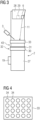
- Figure 5 shows the time course along the abscissa 35, and the deviation of the current orientation of the biopsy needle 8 from the target orientation along the ordinate 36.
- the solid graph 37 shows the time course of the made setting, while the dashed graphs 38 show the course of a target range around the target orientation that narrows over time (i.e. deviation zero).
- haptic feedback is output via the output device 17, so that, as can be seen from the course 37, the user is guided intuitively and naturally over time, from a rough setting to a fine adjustment, to the target orientation.
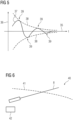
- Figure 6 shows a possible visual, graphical representation 40 on the display 16.
- the position of the biopsy needle 8 shown here in a stylized manner can be displayed in relation to the target orientation 41, shown by a dashed line.
- the visual representation 40 can be updated in real time and can also be supplemented by further elements, in particular a display 42 of the target penetration depth, only indicated schematically here.
- the representation 40 can be designed in color.
Landscapes
- Health & Medical Sciences (AREA)
- Life Sciences & Earth Sciences (AREA)
- Engineering & Computer Science (AREA)
- Medical Informatics (AREA)
- Surgery (AREA)
- Animal Behavior & Ethology (AREA)
- Heart & Thoracic Surgery (AREA)
- General Health & Medical Sciences (AREA)
- Public Health (AREA)
- Molecular Biology (AREA)
- Veterinary Medicine (AREA)
- Biomedical Technology (AREA)
- Nuclear Medicine, Radiotherapy & Molecular Imaging (AREA)
- Pathology (AREA)
- Radiology & Medical Imaging (AREA)
- Optics & Photonics (AREA)
- Physics & Mathematics (AREA)
- High Energy & Nuclear Physics (AREA)
- Biophysics (AREA)
- Oral & Maxillofacial Surgery (AREA)
- Dentistry (AREA)
- Gynecology & Obstetrics (AREA)
- Robotics (AREA)
- Apparatus For Radiation Diagnosis (AREA)
Abstract
Die Erfindung betrifft eine Biopsieeinrichtung (1) zum Durchführen einer Biopsie an einer weiblichen Brust (10), aufweisend:
- eine Bildgebungseinrichtung (2) zur Tomosynthese der Brust (10) mit einer Kompressionseinrichtung (43) zur Fixierung der Brust (10),
- ein handgehaltenes Biopsiegerät (3) mit einer Biopsienadel, wobei das Biopsiegerät (3) einen Lagesensor (12) zur Messung von die Orientierung der Biopsienadel (8) anzeigenden Lageinformationen aufweist,
- eine mit der Bildgebungseinrichtung (2) registrierte Markierungseinrichtung (6) zur Markierung eines Eintrittspunktes für die Biopsienadel (8) auf der in der Kompressionseinrichtung (43) fixierten Brust (10) gemäß einer auf Bilddaten der Bildgebungseinrichtung (2) basierenden Planungsinformation für eine durchzuführende Biopsie,
- eine Ausgabeeinrichtung (5) zur Ausgabe einer Führungsinformation, die die relative Orientierung der Biopsienadel (8) gemäß der Lageinformation zu einer Sollorientierung (41) gemäß der Planungsinformation anzeigt, für eine die Biopsie durchführende Person, und
- eine Steuereinrichtung (4) zur Steuerung der Biopsieeinrichtung (1) gemäß der Planungsinformation.
Description
- Die Erfindung betrifft eine Biopsieeinrichtung zum Durchführen einer Biopsie an einer weiblichen Brust, die eine Bildgebungseinrichtung zur Tomosynthese der Brust mit einer Kompressionseinrichtung zur Fixierung der Brust aufweist. Daneben betrifft die Erfindung ein Verfahren zur Unterstützung einer eine Biopsie mit einer Biopsieeinrichtung durchführenden Person und ein Biopsiegerät.
- Biopsien an der weiblichen Brust (Mamma) oder am sonstigen Stellen des menschlichen Körpers werden üblicherweise durchgeführt, um anatomische Auffälligkeiten, insbesondere Gewebeveränderungen, genauer untersuchen und in der Folge diagnostizieren zu können. Dies liegt darin begründet, dass die medizinische Bildgebung, beispielsweise Brust-Tomosynthese, häufig nicht ausreichend ist, um eine abschließende Diagnose stellen zu können. Bei einer Biopsie wird eine Biopsienadel als medizinisches Instrument genutzt, um möglichst minimalinvasiv an die interessierende Stelle gelangen zu können und dort eine Gewebeprobe zu entnehmen. Beispielsweise ist hierzu die Methodik der sogenannten Stanzbiopsie bekannt.
- In der Biopsie ist es wesentlich, die interessierende Stelle innerhalb der Patientin möglichst exakt zu treffen, das bedeutet, die Biopsienadel muss im dreidimensionalen Raum mit hinreichender Positioniergenauigkeit positioniert werden. Hierfür weisen Biopsieeinrichtungen üblicherweise Bildgebungseinrichtungen, üblicherweise Röntgeneinrichtungen, auf. In vielen Fällen, um an der Biopsieeinrichtung auch ein Screening durchführen zu können, handelt es sich bei der Bildgebungseinrichtung um eine Tomosyntheseeinrichtung. An Biopsieeinrichtungen werden dabei eine Vielzahl von Anforderungen gestellt. Hinsichtlich der Bildgebung sollen Bildartefakte bei der Röntgenaufnahme durch die Biopsienadel und Komponenten einer die Biopsienadel beinhaltenden Biopsieeinheit möglichst vermieden werden, sowohl bei zweidimensionalen Röntgenaufnahmen als auch bei dreidimensionalen Röntgenaufnahmen, insbesondere Tomosynthese-Aufnahmen. Das Biopsiegerät und sonstige patientennah zu positionierende Komponenten sollen möglichst geringen Bauraum auf und an dem Objekttisch in Anspruch nehmen, um den Zugang zur Patientin und zum Untersuchungsbereich nicht einzuschränken. Die Behandlungsdauer soll möglichst kurz sein. Beispielsweise bedeutet dies, dass motorische Positionierungsfahrten von kurzer Dauer sein sollten. Schließlich sind ein geringes Gewicht und geringe Kosten wünschenswert.
- Im Stand der Technik wurden bereits Ausgestaltungen von Biopsieeinrichtungen vorgeschlagen, bei denen eine Biopsieeinheit, die Aktoren zum Positionieren und Bewegen der Biopsienadel aufweisen, am Objekttisch und/oder am Stativ der Bildgebungseinrichtung befestigt wird. Die gesamte Biopsieeinheit ist dabei mit dem Koordinatensystem der Bildgebungseinrichtung registriert, sodass eine mithilfe von Bilddaten der Bildgebungseinrichtung erhaltene Planungsinformation unmittelbar in eine Ansteuerung der insbesondere als Elektromotoren ausgebildeten Aktoren umgesetzt werden kann, um vollständig automatisch eine Gewebeentnahme durchzuführen.
- Eine derartige Ausgestaltung ist jedoch dahingehend nachteilhaft, dass derartige, fest installierte bzw. fest installierbare Biopsieeinheiten aufwendig sind, einen großen Bauraum einnehmen und auf verlässliche und robuste Weise hochkomplexe derart umgesetzt werden müssen, dass die interessierende Stelle hinreichend genau getroffen wird. Darüber hinaus ist die Akzeptanz seitens der Patientinnen teilweise eingeschränkt, da die Biopsie vollautomatisch ohne Mitwirkung eines Vertrauen erweckenden Menschen durchgeführt wird.
- Der Erfindung liegt daher die Aufgabe zugrunde, eine Biopsieeinrichtung anzugeben, die trotz kostengünstiger, bauraumsparender Realisierbarkeit auf einfache Weise eine hochgenaue Biopsie erlaubt.
- Zur Lösung dieser Aufgabe sind erfindungsgemäß eine Biopsieeinrichtung, ein Verfahren und ein Biopsiegerät gemäß den unabhängigen Patentansprüchen vorgesehen. Vorteilhafte Ausgestaltungen ergeben sich aus den Unteransprüchen.
- Eine Biopsieeinrichtung zum Durchführen einer Biopsie an einer weiblichen Brust weist erfindungsgemäß auf:
- eine Bildgebungseinrichtung zur Tomosynthese der Brust mit einer Kompressionseinrichtung zur Fixierung der Brust,
- ein handgehaltenes Biopsiegerät mit einer Biopsienadel, wobei das Biopsiegerät einen Lagesensor zur Messung von die Orientierung der Biopsienadel anzeigenden Lageinformationen aufweist,
- eine mit der Bildgebungseinrichtung registrierte Markierungseinrichtung zur Markierung eines Eintrittspunktes für die Biopsienadel auf der in der Kompressionseinrichtung fixierten Brust gemäß einer auf Bilddaten der Bildgebungseinrichtung basierenden Planungsinformation für eine durchzuführende Biopsie,
- eine Ausgabeeinrichtung zur Ausgabe einer Führungsinformation, die die relative Orientierung der Nadel gemäß der Lageinformation zu einer Sollorientierung gemäß der Planungsinformation anzeigt, für eine die Biopsie durchführende Person, und
- eine Steuereinrichtung zur Steuerung der Biopsieeinrichtung gemäß der Planungsinformation.
- Dabei ist der Lagesensor zur Aufnahme von Sensordaten, die die Orientierung der Biopsienadel in drei Dimensionen beschreiben, ausgebildet. Der Lagesensor kann insbesondere ein gyroskopischer Sensor sein, aber auch anderweitig ausgestaltet sein.
- Erfindungsgemäß wird mithin vorgeschlagen, ein handgehaltenes Biopsiegerät, welches die Biopsienadel beinhaltet und einen Lagesensor aufweist, mit einer Markierungseinrichtung derart zu kombinieren, dass auf platzsparende und kostengünstige Weise dennoch eine hochgenaue Positionierung der Biopsienadel zur Entnahme der Gewebeprobe auf Basis einer Planungsinformation, die auf Bilddaten der Bildgebungseinrichtung beruht, möglich ist. Hierbei wird eine Ausgabeeinrichtung verwendet, die die Person, die die Biopsie durchführt, derart informiert, dass die Biopsienadel gemäß der Sollorientierung ausgerichtet werden kann. Über den Soll-Eintrittspunkt wird mittels der Markierungseinrichtung informiert.
- Auf diese Weise kann die Biopsieeinrichtung äußerst kostengünstig und handlich realisiert werden, da keinerlei Motoren, Leistungselektronik oder bewegliche Achsen- und/oder Präzisionsführungen benötigt werden. Das Biopsiegerät kann mit sehr geringem Gewicht umgesetzt werden und daher durch die die Biopsie durchführende Person gut geführt werden, insbesondere zur Einstellung der Sollorientierung. Nachdem das handgehaltene Biopsiegerät vom Objekttisch entfernt werden kann und insbesondere nicht, wie eine hochkomplexe, schwere Biopsieeinheit des Standes der Technik, am Objekttisch oder dem Stativ befestigt werden muss, existieren gegenüber einer Bildgebungseinrichtung alleine kaum Bauraumeinschränkungen und der freie Zugang zur Patientin wird vollständig erhalten. Zugleich liegt ein hohes Sicherheitsgefühl für die Patientinnen vor, da der Eingriff handgeführt durch einen Menschen durchgeführt wird.
- Es ist eine schnelle Probenentnahme, wie beispielsweise auch bei der ultraschallgeführten Biopsie, möglich. Nachdem keine Biopsieeinheit installiert werden muss, ist kein Umrüstaufwand zwischen dem Screening und der Biopsie notwendig. Hierbei sei angemerkt, dass der erfindungsgemäße Vorschlag auf einfache Art und Weise auch eine Nachrüstung bestehender Bildgebungseinrichtungen, insbesondere von Mammografieeinrichtungen, zur Bildung einer Biopsieeinrichtung erlaubt, nachdem letztlich lediglich die Markierungseinrichtung und das handgehaltene Biopsiegerät hinzugefügt werden müssen. Eine Steuereinrichtung und ein Display oder dergleichen sind meist bereits vorhanden.
- Im konkreten Betrieb wird immer dann, wenn eine Planungsinformation vorliegt, die beispielsweise einen gewünschten Pfad der Biopsienadel beschreiben kann, der Eintrittspunkt an die Markierungseinrichtung übertragen bzw. die Markierungseinrichtung gemäß dem Eintrittspunkt zu dessen Markierung angesteuert. Anders gesagt kann die Steuereinrichtung insgesamt zum Übertragen des Eintrittspunktes an die Markierungseinrichtung und/oder zur Ansteuerung der Markierungseinrichtung gemäß dem Eintrittspunkt ausgebildet sein.
- Insbesondere kann die Markierungseinrichtung einen Markierungslaser aufweisen. Es ist also denkbar, den Eintrittspunkt durch Licht auf der Oberfläche der Patientin zu markieren. Hierzu ist die Verwendung von Laserlicht aufgrund dessen guter Erkennbarkeit bevorzugt, wobei jedoch auch andere Arten von Projektionseinrichtungen verwendet werden können. Eine beispielhaft einsetzbare Markierungseinrichtung wurde beispielsweise in der Veröffentlichung "Integration eines Projektors zur Einblendung von Positionier- und Untersuchungshilfen" in Prior Art Journal 2020 #05 - Pages: 119-122 - ISBN: 978-3-947591-33-6; Volume No.: 99, beschrieben.
- Zweckmäßigerweise kann die Markierungseinrichtung an der Bildgebungseinrichtung angeordnet sein. Durch eine Anordnung der Markierungseinrichtung an der Bildgebungseinrichtung ist eine Registrierung auf besonders einfache Art und Weise gegeben. Konkret und besonders bevorzugt kann die Markierungseinrichtung dabei an einer den Röntgenstrahler der Bildgebungseinrichtung umfassenden Strahlereinheit angeordnet sein bzw. in diese integriert sein. Bei Mammografieeinrichtungen und bekannten Biopsieeinrichtungen ist es bekannt, den Röntgendetektor mit einer Abdeckung selbst als Objekttisch einzusetzen, wobei die Brust mittels einer zusätzlichen, oberen Kompressionsplatte (auch als Kompressionspaddle bezeichnet) komprimiert und in der Position gehalten werden kann. Der Röntgenstrahler ist in der Strahlereinheit, bei möglicher Tomosynthese beweglich, oberhalb des Objekttisches und der Kompressionsplatte angeordnet, von wo sich hervorragend die Soll-Eintrittsposition markieren lässt.
- In diesem Zusammenhang ist es auch besonders vorteilhaft, wenn die Kompressionseinrichtung die obere, insbesondere von dem Röntgendetektor der Bildgebungseinrichtung abgewandt die Brust komprimierende Kompressionsplatte aufweist, wobei die Kompressionsplatte wenigstens eine Durchgangsöffnung zum Durchführen der Biopsienadel aufweist. Wie bereits erwähnt, liegt dabei die Brust unten bevorzugt auf einer Detektorabdeckung des Röntgendetektors auf, die den Objekttisch bildet. Es wird also eine obere Kompressionsplatte verwendet, die Zugang zur Brust zumindest in durch die Durchgangsöffnungen, insbesondere wenigstens ein Fenster, definierten Bereichen gestattet. Diese Durchgangsöffnungen können zum einen genutzt werden, um den Eintrittspunkt, bevorzugt, wie erwähnt, von oben, zu projizieren, zum anderen auch, um mit der Biopsienadel des Biopsiegeräts Zugang zu erhalten. In einer konkreten Ausgestaltung kann vorgesehen sein, dass die Kompressionsplatte mehrere, matrixartig angeordnete Durchgangsöffnungen aufweist. Eine solche Kompressionsplatte kann auch als "alphanumerische Kompressionsplatte" bezeichnet werden, nachdem eine Art "Schachbrettmuster" für die Durchgangsöffnungen vorgesehen sein kann und die einzelnen Durchgangsöffnungen mit einem Buchstaben (für eine Richtung) und einer Zahl (für die andere Richtung) identifiziert werden können.
- In Weiterbildung der Erfindung kann vorgesehen sein, dass sie eine, insbesondere an der Bildgebungseinrichtung angeordnete, Halterung für das Biopsiegerät aufweist. Beispielsweise kann die Halterung seitlich an der Bildgebungseinrichtung, insbesondere an einem Stativ der Bildgebungseinrichtung, angeordnet sein, jedoch sind auch andere Anordnungspositionen denkbar. In der Halterung kann das Biopsiegerät abgelegt werden, solange es nicht benötigt wird, beispielsweise, wenn die Bildgebungseinrichtung zum Screening verwendet werden soll. Zweckmäßigerweise kann die Halterung verschiedenen weiteren Funktionen dienen.
- So kann konkret vorgesehen sein, dass die Halterung eine vorbestimmte Kalibrierungsorientierung des Biopsiegeräts zum Kalibrieren des Lagesensors herstellend ausgebildet ist. Dies kann beispielsweise anhand einer Formgebung und/oder anhand entsprechend gewählter Stützflächen erreicht werden. Insbesondere kann die Halterung so ausgestaltet sein, dass das Biopsiegerät nur in der bestimmten Kalibrierungsorientierung passgenau in sie eingesetzt werden kann. Immer also dann, wenn das Biopsiegerät in die Halterung eingesetzt ist, kann der Lagesensor neu kalibriert werden, so dass die Lageinformation immer klar definiert in einer mit der Bildgebungseinrichtung registrierten Art ermittelt werden kann.
- Die Halterung kann ferner eine elektrische Schnittstelle zum Aufladen eines elektrischen Energiespeichers des Biopsiegeräts aufweisen. Hierbei kann die Schnittstelle beispielsweise halterungsseitige Anschlussmittel umfassen, die mit biopsiegeräteseitigen Anschlussmitteln zusammenwirken. Insbesondere wird beim Einsetzen des Biopsiegeräts in die Halterung unmittelbar auch die elektrische Verbindung zum Aufladen des elektrischen Energiespeichers hergestellt. Die Halterung kann in diesem Sinne auch als eine Art "Ladeschale" verstanden werden.
- Auch allgemein gesprochen ist es zweckmäßig, wenn das Biopsiegerät kabellos ausgestaltet ist, mithin keinerlei Anschlusskabel benötigt, die bei der Biopsie stören und/oder behindern könnten. Konkret kann vorgesehen sein, dass, insbesondere zusätzlich zu dem Energiespeicher, das Biopsiegerät eine Kommunikationseinrichtung zur drahtlosen Kommunikation mit der Steuereinrichtung aufweist. Beispielsweise kann die Kommunikationseinrichtung eine Bluetooth-Einrichtung sein.
- Vorzugsweise kann das Biopsiegerät eine Steuereinheit aufweisen, die über die Kommunikationseinrichtung mit der Steuereinrichtung kommunizieren kann, insbesondere bidirektional. Die Steuereinheit steuert den Betrieb des Biopsiegeräts. Sie kann insbesondere ausgebildet sein, aus den Sensordaten des Lagesensors die Lageinformation zu ermitteln und
- die Lageinformation oder eine daraus abgeleitete Information mittels der Kommunikationseinrichtung an die (biopsiegerätexterne) Steuereinrichtung zu übermitteln und/oder
- eine Abweichung der Orientierung der Biopsienadel von der Sollorientierung, die über die Kommunikationseinrichtung erhalten wurde, zu ermitteln.
- Hierbei ist es insbesondere zweckmäßig, wenn sowohl die Steuereinrichtung über die aktuelle Lageinformation informiert ist als auch die Steuereinheit die Sollorientierung kennt. Denn dann ist es, wie im Folgenden noch genauer dargelegt werden wird, denkbar, die Ausgabeeinrichtung letztlich verteilt umzusetzen, um auf vielfältige Art und Weise die den Eingriff durchführende Person mit Unterstützungshinweisen als Führungsinformation zu unterstützen.
- In einer besonders bevorzugten Ausgestaltung der vorliegenden Erfindung ist vorgesehen, dass das Biopsiegerät ein Ausgabemittel der Ausgabeeinrichtung aufweist, welches zur Ausgabe eines Unterstützungshinweises in Abhängigkeit der relativen Orientierung der Biopsienadel gemäß der Lageinformation zu der Sollorientierung ausgebildet ist. Ist das Ausgabemittel unmittelbar am Biopsiegerät vorgesehen, muss die die Biopsie durchführende Person ihre Aufmerksamkeit nicht von dem Biopsiegerät und dem Eingriffsbereich, insbesondere auch dem markierten Eintrittspunkt, abwenden und kann sich daher auf vereinfachte Weise vollständig auf den Eingriff konzentrieren. Dabei kann die Ansteuerung des Ausgabemittels zweckmäßig durch die oben beschriebene Steuereinheit direkt erfolgen, wenn die Abweichung von der Sollorientierung, wie oben beschrieben, biopsiegeräteintern ermittelt wird. In diesem Fall muss also lediglich dem Biopsiegerät die Sollorientierung von der Steuereinrichtung bereitgestellt werden, wozu die Kommunikationseinrichtung genutzt werden kann, damit das Biopsiegerät autark durch entsprechende Ausgaben über das Ausgabemittel die die Biopsie durchführende Person zur Einnahme der Sollorientierung führen kann, während der Eintrittspunkt extern durch die mit der Bildgebungseinrichtung registrierte Markierungseinrichtung angezeigt wird.
- Besonders bevorzugt kann dabei das Ausgabemittel ein haptisches Ausgabemittel sein. Konkret kann es sich bei dem haptisches Ausgabemittel um einen Vibrationsmotor handeln. Auf diese Weise kann die den Eingriff durchführende Person den Blick weiterhin auf den tatsächlichen Biopsiebereich, insbesondere den Eintrittspunkt und die Biopsienadel, richten, nachdem sich das Ausgabemittel an andere Sinne richtet. Da das Biopsiegerät handgehalten ist, sind Vibrationen gut spürbar. Zusätzlich oder alternativ kann das Ausgabemittel auch ein akustisches Ausgabemittel sein. Auch ist ein optisches Ausgabemittel denkbar, zumindest alleinstehend jedoch weniger bevorzugt. Dabei ist es grundsätzlich denkbar, Feedback immer dann zu geben, wenn sich die Biopsienadel in der Sollorientierung befindet. Bevorzugt ist es jedoch, das Feedback über das Ausgabemittel, insbesondere das haptische Ausgabemittel, zu nutzen, um die die Biopsie durchführende Person schrittweise zu der Sollorientierung zu führen.
- In einer konkreten, vorteilhaften Ausgestaltung kann daher das Ausgabemittel gemäß einem sich über die Zeit verkleinernden, einzustellenden Zielbereich um die Sollorientierung zur schrittweisen Führung der die Biopsie durchführenden Person zu der Sollorientierung ansteuerbar sein. Insbesondere kann also die Steuereinheit ausgebildet sein, diese Ansteuerung durchzuführen. Mit anderen Worten wird vorgeschlagen, von einem großen "Fangbereich" zu einem kleineren "Fangbereich" überzugehen. Hierbei kann konkret vorgesehen sein, dass das Ausgabemittel bei Verlassen des Zielbereichs aktiviert wird. Das bedeutet, immer dann, wenn die die Biopsie durchführende Person droht, den Zielbereich zu verlassen, wird sie durch entsprechendes Feedback wieder in diesen zurückgeleitet. Mit der zunehmenden Verkleinerung des Zielbereichs über die Zeit wird somit immer genauer die Sollorientierung eingenommen, indem erst zu einem groben Zielbereich geführt wird, welcher dann zunehmend verengt wird. Somit ist eine besonders intuitive Zielführung zur Sollorientierung gegeben.
- Es sind auch andere Ansätze denkbar, das Ausgabemittel konkret zu nutzen, beispielsweise im Fall eines akustischen Ausgabemittels den Benutzer nach Art einer "Einparkhilfe" zu der Sollorientierung zuführen, indem bei größerem Abstand zur Sollorientierung zeitlich beabstandete Töne ausgegeben werden, deren zeitlicher Abstand zueinander kleiner wird, bis ein Durchgangston bei Erreichen der Sollorientierung vorliegt.
- Alternativ oder vorzugsweise zusätzlich kann vorgesehen sein, dass die Ausgabeeinrichtung ein Display umfasst, wobei die Steuereinrichtung zur Ansteuerung des Displays zur Ausgabe einer die relative Orientierung der Nadel gemäß der Lageinformation zu der Sollorientierung visualisierenden Darstellung ansteuert. Die Darstellung bildet dann also die Führungsinformation. Hierbei kann beispielsweise ein Display verwendet werden, das durch die Bildgebungseinrichtung auch eingesetzt wird, um Bilddaten darzustellen und dergleichen. Bei dem Display kann es sich auch um einen Touchscreen handeln, der zusätzlich als Eingabeeinrichtung nutzbar ist. Bevorzugt ist das Display in einem Sichtbereich der die Biopsie durchführenden Person angeordnet oder anordenbar, beispielsweise mittels einer verstellbaren Halteeinrichtung, wie beispielsweise einem Haltearm.
- Das Display wird hierbei bevorzugt von der Steuereinrichtung direkt gesteuert, welche mittels der Kommunikationseinrichtung die Lageinformation von dem Biopsiegerät erhält. Die graphische Darstellung kann insbesondere eine abstrahierte und/oder schematische Darstellung der Biopsienadel in der aktuellen, durch die Lageinformation beschriebenen Orientierung im Vergleich zu der durch ein zusätzliches Element dargestellten Sollorientierung enthalten. Diese Darstellung kann beispielsweise als Überlagerung von Bilddaten, insbesondere solchen Bilddaten, die der Planungsinformation zugrunde liegen, ermittelt werden. Auch bezüglich des Hintergrunds ist jedoch eine Abstraktion möglich, insbesondere, nachdem im Allgemeinen die aktuelle tatsächliche räumliche Position der Biopsienadel - im Gegensatz zu ihrer Orientierung - nicht bekannt ist und somit eine Verwirrung vermieden werden kann.
- Die Biopsieeinrichtung kann ferner eine Planungseinrichtung zur wenigstens teilweise automatischen Ermittlung der Planungsinformation aus Bilddaten der Bildgebungseinrichtung aufweisen. Dabei können beispielsweise mit der Bildgebungseinrichtung zwei- oder dreidimensionale Scout-Scans aufgenommen werden, die wenigstens teilweise automatisch durch die Planungseinrichtung, welche beispielsweise eine Workstation umfassen kann, ausgewertet werden können. Beispielsweise kann auf einer Anzeigeeinrichtung der Workstation ein Planungs-Benutzerinterface dargestellt werden, über das ein Benutzer manuell in die Planung eingreifen kann, beispielsweise die interessierende Stelle markieren kann und dergleichen. Planungsvorgänge sowie allgemein Vorgehensweisen zur Ermittlung der Planungsinformation sind im Stand der Technik bereits weitgehend bekannt und sollen hier nicht im Detail dargelegt werden.
- Vorzugsweise kann die Biopsienadel, insbesondere entlang des Nadelschafts, Markierungen zur Anzeige einer Eindringtiefe in eine Patientin aufweisen. So können in regelmäßigen Abständen entlang des Nadelschafts der Biopsienadel Markierungen vorgesehen sein, sodass die aktuelle Eindringtiefe durch die die Biopsie durchführende Person leicht abgelesen werden kann. Die Soll-Eindringtiefe gemäß der Planungsinformation kann beispielsweise mittels der Ausgabeeinrichtung, insbesondere dem Display, zur Referenz ausgegeben werden. Neben den Parametern Eintrittspunkt und Sollorientierung ist es mittels solcher Markierungen auch möglich, die Soll-Eindringtiefe zu überwachen und zu prüfen. Dabei sei angemerkt, dass eine aktuelle Eindringtiefe alternativ oder zusätzlich, falls entsprechende Erfassungsmittel in dem Biopsiegerät vorgesehen sind, auch an einem oder dem Ausgabemittel des Biopsiegeräts ausgegeben werden kann. Auch ist es grundsätzlich denkbar, in dem Biopsiegerät einen Aktor zum automatischen Ausfahren der Biopsienadel vorzusehen, was jedoch weniger bevorzugt ist, da Aktoren, wie angesprochen, bevorzugt vermieden werden, um das Biopsiegerät handhabbar und leicht zu halten.
- Neben der Biopsieeinrichtung betrifft die vorliegende Erfindung auch ein Verfahren zur Unterstützung einer eine Biopsie mit einer erfindungsgemäßen Biopsieeinrichtung durchführenden Person, wobei die Ausgabeeinrichtung zur Ausgabe einer Führungsinformation, die die relative Orientierung der Nadel gemäß der Lageinformation zu einer Sollorientierung gemäß der Planungsinformation anzeigt, angesteuert wird. Sämtliche Ausführungen zur erfindungsgemäßen Biopsieeinrichtung, insbesondere hinsichtlich der Kommunikation, der Steuerung durch die Steuereinrichtung und die Steuereinheit sowie der konkreten Ausgestaltung der Ausgabeeinrichtung, lassen sich analog auf das erfindungsgemäße Verfahren übertragen, mit welchem mithin ebenso die bereits genannten Vorteile erhalten werden können.
- Schließlich betrifft die Erfindung auch ein handgehaltenes Biopsiegerät für eine erfindungsgemäße Biopsieeinrichtung, aufweisend eine Biopsienadel und einen Lagesensor zur Messung von die Orientierung der Biopsienadel anzeigenden Lageinformationen. Auch für das Biopsiegerät gelten die Ausführungen zur Biopsieeinrichtung und zum Verfahren, soweit anwendbar, analog fort. Insbesondere kann das Biopsiegerät daher auch die Steuereinheit, den elektrischen Energiespeicher, die Kommunikationseinrichtung und/oder Anschlussmittel zum Aufladen des elektrischen Energiespeichers aufweisen. Besonders bevorzugt jedoch weist das Biopsiegerät ein Ausgabemittel auf, das, wie oben beschrieben, insbesondere durch die Steuereinheit ansteuerbar ist, um die relative Orientierung zu bzw. Abweichung von einer, insbesondere über die Kommunikationseinrichtung erhaltenen, Sollorientierung anzuzeigen, beispielsweise gemäß einem zeitlich kleiner werdenden Zielbereich um die Sollorientierung.
- Weitere Vorteile und Einzelheiten der vorliegenden Erfindung ergeben sich aus den im Folgenden beschriebenen Ausführungsbeispielen sowie anhand der Zeichnungen. Dabei zeigen:
- Fig. 1
- eine Skizze funktionaler Komponenten einer erfindungsgemäßen Biopsieeinrichtung,
- Fig. 2
- eine perspektivische Ansicht eines Biopsiegeräts,
- Fig. 3
- eine Ansicht eines Teils einer Bildgebungseinrichtung,
- Fig. 4
- eine Kompressionsplatte,
- Fig. 5
- einen Graphen zur Erläuterung der Ansteuerung eines Ausgabemittels, und
- Fig. 6
- eine mögliche visuelle Darstellung auf einem Display.
-
Fig. 1 zeigt den funktionalen Aufbau einer erfindungsgemäßen Biopsieeinrichtung 1. Die Biopsieeinrichtung 1 umfasst als hauptsächliche Komponenten eine hier nicht näher aufgeschlüsselte Bildgebungseinrichtung 2, ein handgehaltenes, kabelloses Biopsiegerät 3, eine Steuereinrichtung 4, eine vorliegend in mehrere Komponenten aufgeteilte Ausgabeeinrichtung 5 und eine Markierungseinrichtung 6, die vorliegend an der Bildgebungseinrichtung 2 befestigt oder in dieser integriert ist. Zusätzlich umfasst die Biopsieeinrichtung 1 vorliegend noch eine Planungseinrichtung 44, die beispielsweise als eine Workstation ausgebildet sein kann. - Die Planungseinrichtung 44 ist ausgebildet, wenigstens teilweise automatisch basierend auf Bilddaten der Bildgebungseinrichtung 2, vorliegend eine Röntgeneinrichtung zur Tomosynthese der weiblichen Brust, eine Planung durchzuführen, an der auch ein Benutzer beteiligt sein kann. Das Ergebnis der Planung ist eine Planungsinformation, die insbesondere angibt, wie eine Biopsienadel 8 des Biopsiegeräts 3, die dort mittels einer Nadelhalterung 9 befestigt ist, zu einer interessierenden Stelle, wo eine Gewebeprobe entnommen werden soll, innerhalb der aktuell zu behandelnden, hier schematisch angedeuteten Brust 10 gelangen soll. Die Planungsinformation beschreibt also insbesondere einen Soll-Eintrittspunkt, eine Sollorientierung und auch eine Soll-Eindringtiefe der Biopsienadel 8. Diese Planungsinformation wird der Steuereinrichtung 4 bereitgestellt.
- Die Steuereinrichtung 4 gibt vorliegend den Eintrittspunkt an die Markierungseinrichtung 6 weiter, welche einen Markierungslaser 7 aufweist und mit der Bildgebungseinrichtung 2, auf deren Koordinatensystem sich auch die Planungsinformation bezieht, registriert ist. Daher kann die Markierungseinrichtung 6 den Eintrittspunkt gemäß dem gestrichelten Pfeil 11 für eine die Biopsie durchführende Person auf die Brust 10 hochgenau projizieren.
- Um auch die Sollorientierung korrekt einstellen zu können, weist das Biopsiegerät 3 einen Lagesensor 12, beispielsweise einen gyroskopischen Sensor, auf, der die aktuelle Orientierung des Biopsiegeräts 3 in allen drei Raumrichtungen vermessen kann. Die Sensordaten des Lagesensors 12 werden durch eine Steuereinheit 13 des Biopsiegeräts 3 zu einer Lageinformation ausgewertet. Über eine Kommunikationseinrichtung 14 kann das Biopsiegerät 3 drahtlos mit der Steuereinrichtung 4 kommunizieren, wie durch den Pfeil 15 angedeutet ist. Vorliegend ist die Kommunikationseinrichtung 14 als ein Bluetooth-Modul ausgebildet und die Steuereinrichtung 4 Bluetooth-fähig. Von der Steuereinrichtung 4 erhält die Steuereinheit 13 über die Kommunikationseinrichtung 14 die Sollorientierung bereitgestellt, sodass sie eine Abweichung der aktuellen Orientierung des Biopsiegeräts 3 und somit der Biopsienadel 8 von der Sollorientierung feststellen kann. Gleichzeitig kann die Steuereinheit 13 der Steuereinrichtung 4 über die Kommunikationseinrichtung 14 die Lageinformation bereitstellen.
- Die Steuereinrichtung 4 sowie die Steuereinheit 13 nutzen unterschiedliche Komponenten der Ausgabeeinrichtung 5, um der die Biopsie durchführenden, das Biopsiegerät 3 in der Hand haltenden Person als Führungsinformation Unterstützungshinweise, die sie zur Einnahme der Sollorientierung durch die Biopsienadel 8 führen, zu geben.
- Konkret weist zunächst die Biopsieeinrichtung 1 im Allgemeinen ein Display 16 als Teil der Ausgabeeinrichtung 5 auf, auf dem eine grafische Darstellung visuell eine potentielle Abweichung von der Sollorientierung anzeigt. Eine derartige Darstellung kann seitens der Steuereinrichtung 4 aufgrund der Lageinformation leicht erzeugt werden.
- Ferner weist das Biopsiegerät 3 als weitere Komponente der Ausgabeeinrichtung 5 ein Ausgabemittel 17 auf, vorliegend ein haptisches Ausgabemittel, dass als Vibrationsmotor ausgestaltet ist. So kann unmittelbar und ohne, dass die Person den Blick vom Eingriffsgebiet abwenden muss, eine Ausgabe von Unterstützungshinweisen erfolgen, wie im Folgenden noch genauer erläutert werden wird. Die Unterstützungshinweise werden in Abhängigkeit von der durch die Steuereinheit 13 ermittelten Abweichung von der Sollorientierung ausgegeben.
- Die Steuereinheit 13 ist vorliegend als ein Mikrocontroller ausgebildet und weist Firmware auf, um die beschriebenen Funktionen auszuführen.
- Um die Komponenten des Biopsiegeräts 3 mit elektrischer Energie versorgen zu können, weist das Biopsiegerät 3 ferner einen aufladbaren elektrischen Energiespeicher 18 auf, beispielsweise eine Batterie. Dank der drahtlosen Kommunikation über die Kommunikationseinrichtung 14 und der integrierten elektrischen Energieversorgung ist das Biopsiegerät 3 kabellos.
- Das Biopsiegerät 3 kann, wenn es nicht benötigt wird, in einer Halterung 19 aufbewahrt werden, die beispielsweise an einem Stativ der Bildgebungseinrichtung 2 angeordnet sein kann. Die Halterung ist so ausgebildet, dass das Biopsiegerät 3 nur in einer vorbestimmten Kalibrierungsorientierung in die Halterung 19 eingesetzt werden kann. Immer dann, wenn das Biopsiegerät 3 in der Halterung 19 eingesetzt ist, kann also eine Nachkalibrierung des Lagesensors 12 erfolgen, nachdem die Kalibrierungsorientierung dann bekannt ist. Dass dies der Fall ist, kann beispielsweise dadurch festgestellt werden, dass auch eine Verbindung von Anschlussmitteln 20 des Biopsiegeräts 3 mit Anschlussmitteln 21 einer elektrischen Schnittstelle 22 zum Aufladen des Energiespeichers 18 seitens der Halterung 19 aufgebaut ist, was bei Einsetzen des Biopsiegeräts 3 in die Halterung 19 bevorzugt automatisch geschieht.
-
Figur 2 zeigt perspektivisch eine Ansicht einer möglichen Ausgestaltung des Biopsiegeräts 3. Die inFigur 1 gezeigten Komponenten des Biopsiegeräts 3 sind in einem Gehäuse 23 aufgenommen, welches Handhabungsmittel 24, beispielsweise Griffe, zur verbesserten Handhabung des Biopsiegeräts 3 aufweisen kann. Wie ausFigur 2 ebenso ersichtlich ist, sind entlang des Nadelschafts der Biopsienadel 8 in regelmäßigen Abständen Markierungen 25 vorgesehen, an denen die Eindringtiefe der Biopsienadel 8 in die Brust 10 abgelesen werden kann, vergleiche auch Pfeil 26 (Figur 1 ). - Nachdem die Soll-Eindringtiefe auch auf dem Display 16 angezeigt wird, kann somit auch diese durch die die Biopsie durchführende Person leicht eingehalten werden. Auch seitens des Biopsiegeräts 3 können weitere Ausgabemittel vorgesehen sein, um die Soll-Eindringtiefe anzuzeigen.
-
Figur 3 zeigt eine Ansicht der Bildgebungseinrichtung 2, vorliegend eine zur Tomosynthese der Brust 10 ausgebildete Röntgeneinrichtung. Sie umfasst daher ein Stativ 27, an dem eine Strahlereinheit 28 mit dem Röntgenstrahler 29 sowie ein Röntgendetektor 30 mit einer Abdeckung 31 als Objekttisch 32 angeordnet sind. Eine obere, verschiebbare Kompressionsplatte 33 bildet gemeinsam mit dem Detektor 30 und seiner Abdeckung 31 eine Kompressionseinrichtung 43 für die Brust 10. - Damit durch die Kompressionsplatte 33 (oft auch Kompressionspaddle genannt) die Biopsie erfolgen kann, weist diese, wie die Aufsicht in
Figur 4 zeigt, Durchgangsöffnungen 34 auf, die vorliegend matrixartig angeordnet sind. Die Planungsinformation kann angeben, welche Durchgangsöffnungen 34 zu nutzen ist. Die Durchgangsöffnungen 34 erlauben es auch, den Eintrittspunkt gemäß dem gestrichelten Pfeil 11 auf die Oberfläche der Brust 10 zu projizieren. Sie erlauben ferner das Einführen der Biopsienadel 8 in die Brust 10 (gestrichelter Pfeil 26). - Für eine konkrete Biopsie gemäß einer Planungsinformation kann nun beispielsweise vorgesehen sein, dass die Steuereinrichtung 4 den Eintrittspunkt an die Markierungseinrichtung 6 überträgt und diese zur Projektion des Eintrittspunkts auf die Oberfläche der Brust 10 ansteuert. Die die Biopsie durchführende Person kann nun das Biopsiegerät 3 in die Hand nehmen und die Biopsienadel 8 auf den Eintrittspunkt aufsetzen bzw. leicht einführen. Er nutzt dann die Unterstützungshinweise der Ausgabeeinrichtung 5, um die Sollorientierung einzunehmen, und im Folgenden die Markierungen 25 der Biopsienadel 8, um die korrekte, der Soll-Eindringtiefe entsprechende Eindringtiefe zu wählen.
- Konkrete Varianten zur Unterstützung der die Biopsie vornehmenden Person bei der Einnahme der Sollorientierung werden bezüglich der
Figuren 5 und 6 erläutert. Beide Varianten werden vorzugsweise ergänzend eingesetzt. - Die erste Variante nutzt das haptische Ausgabemittel 17 des Biopsiegeräts 3.
Figur 5 zeigt diesbezüglich entlang der Abszisse 35 den Zeitverlauf, entlang der Ordinate 36 die Abweichung der aktuellen Orientierung der Biopsienadel 8 von der Sollorientierung. Der durchgezogene Graph 37 zeigt den zeitlichen Verlauf der von der die Biopsie durchführenden Person vorgenommenen Einstellung, während die gestrichelten Graphen 38 den Verlauf eines sich zeitlich verengenden Zielbereichs um die Sollorientierung (also Abweichung Null) zeigen. Immer dann, wenn die Abweichung an den Rand des Zielbereichs gerät, vergleiche Stellen 39, wird über das Ausgabemittel 17 haptisches Feedback ausgegeben, sodass, wie aus dem Verlauf 37 ersichtlich ist, der Benutzer über die Zeit intuitiv und natürlich, von einer Grobeinstellung zu einer Feineinstellung, an die Sollorientierung geführt wird. -
Figur 6 zeigt eine mögliche visuelle, grafische Darstellung 40 auf dem Display 16. Unter Nutzung der Lageinformation kann die Lage der hier stilisiert gezeigten Biopsienadel 8 zu der Sollorientierung 41, gezeigt durch eine gestrichelte Linie, angezeigt werden. Die visuelle Darstellung 40 kann in Echtzeit aktualisiert werden und auch durch weitere Elemente ergänzt werden, insbesondere auch eine hier nur schematisch angedeutete Anzeige 42 der Soll-Eindringtiefe. Die Darstellung 40 kann farblich gestaltet sein. - Obwohl die Erfindung im Detail durch das bevorzugte Ausführungsbeispiel näher illustriert und beschrieben wurde, so ist die Erfindung nicht durch die offenbarten Beispiele eingeschränkt und andere Variationen können vom Fachmann hieraus abgeleitet werden, ohne den Schutzumfang der Erfindung zu verlassen.
- Unabhängig vom grammatikalischen Geschlecht eines bestimmten Begriffes sind Personen mit männlicher, weiblicher oder anderer Geschlechteridentität mit umfasst.
Claims (15)
- Biopsieeinrichtung (1) zum Durchführen einer Biopsie an einer weiblichen Brust (10), aufweisend:- eine Bildgebungseinrichtung (2) zur Tomosynthese der Brust (10) mit einer Kompressionseinrichtung (43) zur Fixierung der Brust (10),- ein handgehaltenes Biopsiegerät (3) mit einer Biopsienadel, wobei das Biopsiegerät (3) einen Lagesensor (12) zur Messung von die Orientierung der Biopsienadel (8) anzeigenden Lageinformationen aufweist,- eine mit der Bildgebungseinrichtung (2) registrierte Markierungseinrichtung (6) zur Markierung eines Eintrittspunktes für die Biopsienadel (8) auf der in der Kompressionseinrichtung (43) fixierten Brust (10) gemäß einer auf Bilddaten der Bildgebungseinrichtung (2) basierenden Planungsinformation für eine durchzuführende Biopsie,- eine Ausgabeeinrichtung (5) zur Ausgabe einer Führungsinformation, die die relative Orientierung der Biopsienadel (8) gemäß der Lageinformation zu einer Sollorientierung (41) gemäß der Planungsinformation anzeigt, für eine die Biopsie durchführende Person, und- eine Steuereinrichtung (4) zur Steuerung der Biopsieeinrichtung (1) gemäß der Planungsinformation.
- Biopsieeinrichtung (1) nach Anspruch 1, dadurch gekennzeichnet, dass die Markierungseinrichtung (6) einen Markierungslaser (7) aufweist und/oder an der Bildgebungseinrichtung (2) angeordnet ist.
- Biopsieeinrichtung (1) nach Anspruch 1 oder 2, dadurch gekennzeichnet, dass die Kompressionseinrichtung (43) eine obere, insbesondere von einem Röntgendetektor (30) der Bildgebungseinrichtung (2) abgewandt die Brust (10) komprimierende Kompressionsplatte (33) aufweist, die wenigstens eine Durchgangsöffnung (34) zum Durchführen der Biopsienadel (8) aufweist.
- Biopsieeinrichtung (1) nach einem der vorangehenden Ansprüche, dadurch gekennzeichnet, dass sie (1) eine, insbesondere an der Bildgebungseinrichtung (2) angeordnete, Halterung (19) für das Biopsiegerät (3) aufweist.
- Biopsieeinrichtung (1) nach Anspruch 4, dadurch gekennzeichnet, dass die Halterung (19) eine vorbestimmte Kalibrierungsorientierung des Biopsiegeräts (3) zum Kalibrieren des Lagesensors (12) herstellend ausgebildet ist und/oder eine elektrische Schnittstelle (22) zum Aufladen eines elektrischen Energiespeichers (18) des Biopsiegeräts (3) aufweist.
- Biopsieeinrichtung (1) nach einem der vorangehenden Ansprüche, dadurch gekennzeichnet, dass das Biopsiegerät (3) eine Kommunikationseinrichtung (14) zur drahtlosen Kommunikation mit der Steuereinrichtung (4) aufweist.
- Biopsieeinrichtung (1) nach einem der vorangehenden Ansprüche, dadurch gekennzeichnet, dass das Biopsiegerät (3) ein Ausgabemittel (17) der Ausgabeeinrichtung (5) aufweist, welches zur Ausgabe eines Unterstützungshinweises in Abhängigkeit der relativen Orientierung der Biopsienadel (8) gemäß der Lageinformation zu der Sollorientierung (41) ausgebildet ist.
- Biopsieeinrichtung (1) nach Anspruch 7, dadurch gekennzeichnet, dass das Ausgabemittel (17) ein haptisches Ausgabemittel (17) ist.
- Biopsieeinrichtung (1) nach Anspruch 6 oder 7, dadurch gekennzeichnet, dass das Ausgabemittel (17) gemäß einem sich über die Zeit verkleinernden, einzustellenden Zielbereich um die Sollorientierung (41) zur schrittweisen Führung der die Biopsie durchführenden Person zu der Sollorientierung (41) ansteuerbar ist.
- Biopsieeinrichtung (1) nach Anspruch 9, dadurch gekennzeichnet, dass das Ausgabemittel (17) bei Verlassen des Zielbereichs aktiviert wird.
- Biopsieeinrichtung (1) nach einem der vorangehenden Ansprüche, dadurch gekennzeichnet, dass die Ausgabeeinrichtung (5) ein Display (16) umfasst, wobei die Steuereinrichtung (4) zur Ansteuerung des Displays (16) zur Ausgabe einer die relative Orientierung der Biopsienadel (8) gemäß der Lageinformation zu der Sollorientierung (41) visualisierenden Darstellung (40) ansteuert.
- Biopsieeinrichtung (1) nach einem der vorangehenden Ansprüche, dadurch gekennzeichnet, dass sie ferner eine Planungseinrichtung (44) zur wenigstens teilweise automatischen Ermittlung der Planungsinformation aus Bilddaten der Bildgebungseinrichtung (2) aufweist.
- Biopsieeinrichtung (1) nach einem der vorangehenden Ansprüche, dadurch gekennzeichnet, dass die Biopsienadel (8), insbesondere entlang des Nadelschafts, Markierungen (25) zur Anzeige einer Eindringtiefe in eine Patientin aufweist.
- Verfahren zur Unterstützung einer eine Biopsie mit einer Biopsieeinrichtung (1) nach einem der vorangehenden Ansprüche durchführenden Person, wobei die Ausgabeeinrichtung (5) zur Ausgabe einer Führungsinformation, die die relative Orientierung der Biopsienadel (8) gemäß der Lageinformation zu einer Sollorientierung (41) gemäß der Planungsinformation anzeigt, angesteuert wird.
- Handgehaltenes Biopsiegerät (3) für eine Biopsieeinrichtung (1) nach einem der Ansprüche 1 bis 13, aufweisend eine Biopsienadel (8) und einen Lagesensor (12) zur Messung von die Orientierung der Biopsienadel (8) anzeigenden Lageinformationen.
Priority Applications (3)
| Application Number | Priority Date | Filing Date | Title |
|---|---|---|---|
| EP23179521.2A EP4477181A1 (de) | 2023-06-15 | 2023-06-15 | Biopsieeinrichtung, unterstützungsverfahren und biopsiegerät |
| US18/742,093 US20240415471A1 (en) | 2023-06-15 | 2024-06-13 | Biopsy equipment, support method and biopsy device |
| CN202410762780.7A CN119138931A (zh) | 2023-06-15 | 2024-06-13 | 活检装置、辅助方法以及活检仪 |
Applications Claiming Priority (1)
| Application Number | Priority Date | Filing Date | Title |
|---|---|---|---|
| EP23179521.2A EP4477181A1 (de) | 2023-06-15 | 2023-06-15 | Biopsieeinrichtung, unterstützungsverfahren und biopsiegerät |
Publications (1)
| Publication Number | Publication Date |
|---|---|
| EP4477181A1 true EP4477181A1 (de) | 2024-12-18 |
Family
ID=86851737
Family Applications (1)
| Application Number | Title | Priority Date | Filing Date |
|---|---|---|---|
| EP23179521.2A Pending EP4477181A1 (de) | 2023-06-15 | 2023-06-15 | Biopsieeinrichtung, unterstützungsverfahren und biopsiegerät |
Country Status (3)
| Country | Link |
|---|---|
| US (1) | US20240415471A1 (de) |
| EP (1) | EP4477181A1 (de) |
| CN (1) | CN119138931A (de) |
Citations (6)
| Publication number | Priority date | Publication date | Assignee | Title |
|---|---|---|---|---|
| US5320111A (en) * | 1992-02-07 | 1994-06-14 | Livingston Products, Inc. | Light beam locator and guide for a biopsy needle |
| US5598269A (en) * | 1994-05-12 | 1997-01-28 | Children's Hospital Medical Center | Laser guided alignment apparatus for medical procedures |
| US20090281452A1 (en) * | 2008-05-02 | 2009-11-12 | Marcus Pfister | System and method for a medical procedure using computed tomography |
| US20160296179A1 (en) * | 2015-04-13 | 2016-10-13 | Precisionrad Llc | Laser and accelerometer guided medical device |
| US20180035984A1 (en) * | 2016-08-03 | 2018-02-08 | Siemens Healthcare Gmbh | Biopsy unit |
| US20200246085A1 (en) * | 2015-09-28 | 2020-08-06 | Koninklijke Philips N.V. | Optical registation of a remote center of motion robot |
-
2023
- 2023-06-15 EP EP23179521.2A patent/EP4477181A1/de active Pending
-
2024
- 2024-06-13 US US18/742,093 patent/US20240415471A1/en active Pending
- 2024-06-13 CN CN202410762780.7A patent/CN119138931A/zh active Pending
Patent Citations (6)
| Publication number | Priority date | Publication date | Assignee | Title |
|---|---|---|---|---|
| US5320111A (en) * | 1992-02-07 | 1994-06-14 | Livingston Products, Inc. | Light beam locator and guide for a biopsy needle |
| US5598269A (en) * | 1994-05-12 | 1997-01-28 | Children's Hospital Medical Center | Laser guided alignment apparatus for medical procedures |
| US20090281452A1 (en) * | 2008-05-02 | 2009-11-12 | Marcus Pfister | System and method for a medical procedure using computed tomography |
| US20160296179A1 (en) * | 2015-04-13 | 2016-10-13 | Precisionrad Llc | Laser and accelerometer guided medical device |
| US20200246085A1 (en) * | 2015-09-28 | 2020-08-06 | Koninklijke Philips N.V. | Optical registation of a remote center of motion robot |
| US20180035984A1 (en) * | 2016-08-03 | 2018-02-08 | Siemens Healthcare Gmbh | Biopsy unit |
Non-Patent Citations (1)
| Title |
|---|
| "Integration eines Projektors zur Einblendung von Positionier- und Untersuchungshilfen", PRIOR ART JOURNAL, no. 99, 2020, pages 119 - 122, ISBN: 978-3-947591-33-6 |
Also Published As
| Publication number | Publication date |
|---|---|
| US20240415471A1 (en) | 2024-12-19 |
| CN119138931A (zh) | 2024-12-17 |
Similar Documents
| Publication | Publication Date | Title |
|---|---|---|
| DE112008001217B4 (de) | Röntgen-CT-Bildaufnahmegerät | |
| DE69231338T2 (de) | Motorisierte vorrichtung zur biopsie der mamma | |
| EP3486915B1 (de) | Verfahren zur steuerung des betriebs einer medizintechnikeinrichtung, bediengerät, bediensystem und medizintechnikeinrichtung | |
| DE19917867B4 (de) | Verfahren und Vorrichtung zur Bildunterstützung bei der Behandlung von Behandlungszielen mit Integration von Röntgenerfassung und Navigationssystem | |
| EP2168486B1 (de) | Modulares System zur Brustdiagnose und -intervention | |
| DE102004058725B4 (de) | Adapter für chirurgische Navigationsverfolgungsgeräte | |
| DE102005044033B4 (de) | Positionierungssystem für perkutane Interventionen | |
| DE10232676A1 (de) | Verfahren und Vorrichtung zur Positionierung eines Patienten in einem medizinischen Diagnose- oder Therapiegerät | |
| EP1321105A1 (de) | Projektion von Patientenbilddaten aus Durchleuchtungs bzw. Schichtbilderfassungsverfahren auf Oberflächenvideobilder | |
| DE102011005917A1 (de) | Medizinischer Arbeitsplatz | |
| DE102014226756A1 (de) | Bildgebungsanordnung sowie Verfahren zum Positionieren eines Patienten in einer Bildgebungsmodalität | |
| DE102015109371A1 (de) | Vorrichtung und Verfahren zur robotergestützten Chirurgie | |
| DE10232681A1 (de) | Verfahren und Vorrichtung zur Positionierung eines Patienten in einem medizinischen Diagnose-oder Therapiegerät | |
| DE102008016414A1 (de) | Röntgenvorrichtung und medizinischer Arbeitsplatz | |
| EP3329853B1 (de) | Verfahren zur automatischen positionierung eines patienten, medizintechnische einrichtung, computerprogramm und computerlesbares speichermedium | |
| DE10353110A1 (de) | Aktorplattform zur Führung von Endeffektoren bei minimal invasiven Interventionen | |
| DE102008055918A1 (de) | Verfahren zum Betreiben eines medizinischen Navigationssystems und medizinisches Navigationssystem | |
| WO2019149400A1 (de) | Verfahren zur positionsplanung eines aufnahmesystems eines medizinischen bildgebenden geräts und medizinisches bildgebendes gerät | |
| EP2830526B1 (de) | Medizinisches navigationssystem mit drahtlos verbundenem, berührungsempfindlichem bildschirm | |
| DE102010015060A1 (de) | Vorrichtung zur Lagerung, Abtastung, tomographischen Darstellung eines Patienten und Durchführung einer Intervention und Verfahren zur Bestimmung der räumlichen Relation zwischen optischen Aufnahmen und tomographischen Darstellungen | |
| DE69728006T2 (de) | Vorrichtung für chirurgische Eingriffe | |
| DE102009009549A1 (de) | Gerätepositionierung im Operationssaal | |
| EP4477181A1 (de) | Biopsieeinrichtung, unterstützungsverfahren und biopsiegerät | |
| DE102007029199A1 (de) | Verfahren zum Ausrichten eines Zielführungssystems für eine Punktion und Röntgenangiographiesystem | |
| DE4412164A1 (de) | Positionsanzeiger für medizinische Tomographen |
Legal Events
| Date | Code | Title | Description |
|---|---|---|---|
| PUAI | Public reference made under article 153(3) epc to a published international application that has entered the european phase |
Free format text: ORIGINAL CODE: 0009012 |
|
| STAA | Information on the status of an ep patent application or granted ep patent |
Free format text: STATUS: THE APPLICATION HAS BEEN PUBLISHED |
|
| AK | Designated contracting states |
Kind code of ref document: A1 Designated state(s): AL AT BE BG CH CY CZ DE DK EE ES FI FR GB GR HR HU IE IS IT LI LT LU LV MC ME MK MT NL NO PL PT RO RS SE SI SK SM TR |
|
| STAA | Information on the status of an ep patent application or granted ep patent |
Free format text: STATUS: REQUEST FOR EXAMINATION WAS MADE |
|
| 17P | Request for examination filed |
Effective date: 20250616 |