EP4474635A1 - Grätschsitzfahrzeug - Google Patents
Grätschsitzfahrzeug Download PDFInfo
- Publication number
- EP4474635A1 EP4474635A1 EP24178824.9A EP24178824A EP4474635A1 EP 4474635 A1 EP4474635 A1 EP 4474635A1 EP 24178824 A EP24178824 A EP 24178824A EP 4474635 A1 EP4474635 A1 EP 4474635A1
- Authority
- EP
- European Patent Office
- Prior art keywords
- intake
- sound pressure
- pressure level
- sound
- maximum
- Prior art date
- Legal status (The legal status is an assumption and is not a legal conclusion. Google has not performed a legal analysis and makes no representation as to the accuracy of the status listed.)
- Pending
Links
Images


Classifications
-
- F—MECHANICAL ENGINEERING; LIGHTING; HEATING; WEAPONS; BLASTING
- F02—COMBUSTION ENGINES; HOT-GAS OR COMBUSTION-PRODUCT ENGINE PLANTS
- F02M—SUPPLYING COMBUSTION ENGINES IN GENERAL WITH COMBUSTIBLE MIXTURES OR CONSTITUENTS THEREOF
- F02M35/00—Combustion-air cleaners, air intakes, intake silencers, or induction systems specially adapted for, or arranged on, internal-combustion engines
- F02M35/14—Combined air cleaners and silencers
-
- F—MECHANICAL ENGINEERING; LIGHTING; HEATING; WEAPONS; BLASTING
- F02—COMBUSTION ENGINES; HOT-GAS OR COMBUSTION-PRODUCT ENGINE PLANTS
- F02M—SUPPLYING COMBUSTION ENGINES IN GENERAL WITH COMBUSTIBLE MIXTURES OR CONSTITUENTS THEREOF
- F02M35/00—Combustion-air cleaners, air intakes, intake silencers, or induction systems specially adapted for, or arranged on, internal-combustion engines
- F02M35/02—Air cleaners
- F02M35/0201—Housings; Casings; Frame constructions; Lids; Manufacturing or assembling thereof
-
- F—MECHANICAL ENGINEERING; LIGHTING; HEATING; WEAPONS; BLASTING
- F02—COMBUSTION ENGINES; HOT-GAS OR COMBUSTION-PRODUCT ENGINE PLANTS
- F02M—SUPPLYING COMBUSTION ENGINES IN GENERAL WITH COMBUSTIBLE MIXTURES OR CONSTITUENTS THEREOF
- F02M35/00—Combustion-air cleaners, air intakes, intake silencers, or induction systems specially adapted for, or arranged on, internal-combustion engines
- F02M35/02—Air cleaners
- F02M35/04—Air cleaners specially arranged with respect to engine, to intake system or specially adapted to vehicle; Mounting thereon ; Combinations with other devices
- F02M35/048—Arranging or mounting on or with respect to engines or vehicle bodies
-
- F—MECHANICAL ENGINEERING; LIGHTING; HEATING; WEAPONS; BLASTING
- F02—COMBUSTION ENGINES; HOT-GAS OR COMBUSTION-PRODUCT ENGINE PLANTS
- F02M—SUPPLYING COMBUSTION ENGINES IN GENERAL WITH COMBUSTIBLE MIXTURES OR CONSTITUENTS THEREOF
- F02M35/00—Combustion-air cleaners, air intakes, intake silencers, or induction systems specially adapted for, or arranged on, internal-combustion engines
- F02M35/10—Air intakes; Induction systems
- F02M35/10006—Air intakes; Induction systems characterised by the position of elements of the air intake system in direction of the air intake flow, i.e. between ambient air inlet and supply to the combustion chamber
- F02M35/10013—Means upstream of the air filter; Connection to the ambient air
-
- F—MECHANICAL ENGINEERING; LIGHTING; HEATING; WEAPONS; BLASTING
- F02—COMBUSTION ENGINES; HOT-GAS OR COMBUSTION-PRODUCT ENGINE PLANTS
- F02M—SUPPLYING COMBUSTION ENGINES IN GENERAL WITH COMBUSTIBLE MIXTURES OR CONSTITUENTS THEREOF
- F02M35/00—Combustion-air cleaners, air intakes, intake silencers, or induction systems specially adapted for, or arranged on, internal-combustion engines
- F02M35/12—Intake silencers ; Sound modulation, transmission or amplification
- F02M35/1205—Flow throttling or guiding
- F02M35/1227—Flow throttling or guiding by using multiple air intake flow paths, e.g. bypass, honeycomb or pipes opening into an expansion chamber
-
- F—MECHANICAL ENGINEERING; LIGHTING; HEATING; WEAPONS; BLASTING
- F02—COMBUSTION ENGINES; HOT-GAS OR COMBUSTION-PRODUCT ENGINE PLANTS
- F02M—SUPPLYING COMBUSTION ENGINES IN GENERAL WITH COMBUSTIBLE MIXTURES OR CONSTITUENTS THEREOF
- F02M35/00—Combustion-air cleaners, air intakes, intake silencers, or induction systems specially adapted for, or arranged on, internal-combustion engines
- F02M35/16—Combustion-air cleaners, air intakes, intake silencers, or induction systems specially adapted for, or arranged on, internal-combustion engines characterised by use in vehicles
- F02M35/162—Motorcycles; All-terrain vehicles, e.g. quads, snowmobiles; Small vehicles, e.g. forklifts
Definitions
- the present invention relates to a straddled vehicle.
- JP 2000-303925 A discloses a vehicle.
- the vehicle disclosed in JP 2000-303925 A includes an air cleaner, a first introduction duct, and a second introduction duct.
- Each of the first introduction duct and the second introduction duct introduces air into the air cleaner.
- the second introduction duct is longer than the first introduction duct.
- the first introduction duct emits a first intake sound
- the second introduction duct emits a second intake sound.
- the first intake sound and the second intake sound constitute a total intake sound.
- the vehicle provides the total intake sound to a driver of the vehicle.
- JP 2021-46028 A discloses a straddled vehicle.
- the straddled vehicle disclosed in JP 2021-46028 A includes an air cleaner, a first introduction duct, a second introduction duct, and a third introduction duct.
- Each of the first introduction duct, the second introduction duct, and the third introduction duct introduces air into the air cleaner.
- the first introduction duct emits a first intake sound
- the second introduction duct emits a second intake sound
- the third introduction duct emits a third intake sound.
- the first intake sound, the second intake sound, and the third intake sound constitute a total intake sound.
- the straddled vehicle gives the total intake sound to a driver of the straddled vehicle.
- the total intake sound changes.
- the change in the rotation speed of the engine is in a specific range
- the change in the loudness of the total intake sound is severe.
- the change in the rotation speed of the engine is outside a specific range
- the change in loudness of the total intake sound is gradual. In other words, when the rotation speed of the engine changes outside the specific rotation speed range of the engine, the loudness of the total intake sound gradually changes.
- the proportional relationship between the rotation speed of the engine and the loudness of the intake sound is an example of a change in the loudness of the intake sound.
- the relationship between the drastic change in the loudness of the intake sound and the gradual change in the loudness of the intake sound is another example of the change in the loudness of the intake sound.
- the change in the loudness of the intake sound may be a factor that gives the driver a sense of elation. However, it can be considered that only the change in the loudness of the intake sound is not a factor that gives the driver a sense of elation.
- the intake device includes an air cleaner.
- the air cleaner includes an air cleaner case, a filter, an introduction duct, and an intake pipe.
- the air cleaner case forms an internal space.
- the filter is installed in the air cleaner case.
- the filter partitions the internal space into an upstream space and a downstream space.
- the introduction duct introduces air into the upstream space from the outside of the air cleaner case.
- the intake pipe feeds air from the downstream space to the engine.
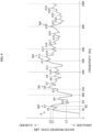
- the first intake sound includes a sound pressure level for each frequency in the middle-frequency range and the high-frequency range.
- the first intake sound includes a first maximum sound pressure level and a second maximum sound pressure level.
- the first maximum sound pressure level is the maximum value of the sound pressure level of the first intake sound in the middle-frequency range. More specifically, the first maximum sound pressure level is a maximum value among sound pressure levels for each frequency of the first intake sound in the middle-frequency range.
- the second maximum sound pressure level is the maximum value of the sound pressure level of the first intake sound in the high-frequency range. More specifically, the second maximum sound pressure level is a maximum value among sound pressure levels for each frequency of the first intake sound in the high-frequency range.
- the third maximum sound pressure level is larger than the first maximum sound pressure level.
- the fourth maximum sound pressure level is larger than the second maximum sound pressure level. Therefore, when the rotation speed of the engine increases from 4000 rpm to 6000 rpm, the middle-frequency range component of the intake sound increases and the high-frequency range component of the intake sound increases.
- the middle-frequency range component and the high-frequency range component are easily heard by the driver.
- the relationship between the middle-frequency range component and the high-frequency range component is close to the relationship between the fundamental tone and the first overtone.
- the middle component and the high component are more easily heard by the driver than the low component and the ultrahigh component.
- the relationship between the middle component and the high component is close to the relationship between the fundamental tone and the first overtone.
- the middle component of the first intake sound and the high component of the first intake sound are emphasized more than the low component of the first intake sound and the ultrahigh component of the first intake sound. Therefore, the first intake sound is more comfortable for the driver. Therefore, the first intake sound effectively gives the driver a sense of elation.
- the second intake sound includes a sound pressure level for each frequency in the low-frequency range and the ultrahigh-frequency range.
- the second intake sound has a seventh maximum sound pressure level and an eighth maximum sound pressure level.
- the seventh maximum sound pressure level is the maximum value of the sound pressure level of the second intake sound in the low-frequency range. More specifically, the seventh maximum sound pressure level is the maximum value among the sound pressure levels for each frequency of the second intake sound in the low-frequency range.
- the eighth maximum sound pressure level is the maximum value of the sound pressure level of the second intake sound in the ultrahigh-frequency range. More specifically, the eighth maximum sound pressure level is the maximum value among the sound pressure levels for each frequency of the second intake sound in the ultrahigh-frequency range.
- the middle component and the high component are more easily heard by the driver than the low component and the ultrahigh component.
- the relationship between the middle component and the high component is close to the relationship between the fundamental tone and the first overtone.
- the middle component of the second intake sound and the high component of the second intake sound are emphasized more than the low component of the second intake sound and the ultrahigh component of the second intake sound. Therefore, the second intake sound is more comfortable for the driver. Therefore, the second intake sound effectively gives the driver a sense of elation.
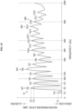
- An intake sound when the engine operates at 8000 rpm is defined as a third intake sound.
- the third intake sound is represented by a relationship between a frequency and a sound pressure level.
- the third intake sound includes a sound pressure level for each frequency in the middle-frequency range and the high-frequency range.
- the third intake sound includes a ninth maximum sound pressure level and a tenth maximum sound pressure level.
- the ninth maximum sound pressure level is the maximum value of the sound pressure level of the third intake sound in the middle-frequency range. Specifically, the ninth maximum sound pressure level is the maximum value among the sound pressure levels for each frequency of the third intake sound in the middle-frequency range.
- the tenth maximum sound pressure level is the maximum value of the sound pressure level of the third intake sound in the high-frequency range. Specifically, the tenth maximum sound pressure level is the maximum value among the sound pressure levels for each frequency of the third intake sound in the high-frequency range.
- the ninth maximum sound pressure level is larger than the third maximum sound pressure level.
- the tenth maximum sound pressure level is larger than the fourth maximum sound pressure level. Therefore, when the rotation speed of the engine increases from 6000 rpm to 8000 rpm, the middle component of the intake sound increases and the high component of the intake sound increases.
- the third intake sound includes a sound pressure level for each frequency in the low-frequency range and the ultrahigh-frequency range.
- the third intake sound includes an eleventh maximum sound pressure level and a twelfth maximum sound pressure level.
- the eleventh maximum sound pressure level is the maximum value of the sound pressure level of the third intake sound in the low-frequency range. More specifically, the eleventh maximum sound pressure level is the maximum value among the sound pressure levels for each frequency of the third intake sound in the low-frequency range.
- the twelfth maximum sound pressure level is the maximum value of the sound pressure level of the third intake sound in the ultrahigh-frequency range. More specifically, the twelfth maximum sound pressure level is the maximum value among the sound pressure levels for each frequency of the third intake sound in the ultrahigh-frequency range.
- the middle component and the high component are more easily heard by the driver than the low component and the ultrahigh component.
- the relationship between the middle component and the high component is close to the relationship between the fundamental tone and the first overtone.
- the middle component of the third intake sound and the high component of the third intake sound are emphasized more than the low component of the third intake sound and the ultrahigh component of the third intake sound. Therefore, the third intake sound is more comfortable for the driver. Therefore, the third intake sound effectively gives the driver a sense of elation.
- the first maximum sound pressure level is remarkably larger than the sound pressure level of the first adjacent peak. Therefore, the first maximum sound pressure level is hardly buried in the sound pressure level of the first adjacent peak. Therefore, the first maximum sound pressure level is more easily heard by the driver.
- the second maximum sound pressure level is remarkably larger than the sound pressure level of the second adjacent peak. Therefore, the second maximum sound pressure level is hardly buried in the sound pressure level of the second adjacent peak. Therefore, the second maximum sound pressure level is more easily heard by the driver.
- the third maximum sound pressure level is remarkably larger than the sound pressure level of the third adjacent peak. Therefore, the third maximum sound pressure level is hardly buried in the sound pressure level of the third adjacent peak. Therefore, the third maximum sound pressure level is more easily heard by the driver.
- the third difference is larger than the first difference.
- the third maximum sound pressure level is more easily heard by the driver than the first maximum sound pressure level. Therefore, when the rotation speed of the engine increases from 4000 rpm to 6000 rpm, the intake sound becomes more comfortable for the driver.
- the fourth maximum sound pressure level is remarkably larger than the sound pressure level of the fourth adjacent peak. Therefore, the fourth maximum sound pressure level is hardly buried in the sound pressure level of the fourth adjacent peak. Therefore, the fourth maximum sound pressure level is more easily heard by the driver.
- the fourth difference is larger than the second difference.
- the ninth maximum sound pressure level is remarkably larger than the sound pressure level of the ninth adjacent peak. Therefore, the ninth maximum sound pressure level is hardly buried in the sound pressure level of the ninth adjacent peak. Therefore, the ninth maximum sound pressure level is more easily heard by the driver.
- the ninth difference is larger than the first difference.
- the ninth maximum sound pressure level is more easily heard by the driver than the first maximum sound pressure level. Therefore, when the rotation speed of the engine increases from 4000 rpm to 8000 rpm, the intake sound becomes more comfortable for the driver.
- the ninth difference is larger than the third difference.
- the ninth maximum sound pressure level is more easily heard by the driver than the third maximum sound pressure level. Therefore, when the rotation speed of the engine increases from 6000 rpm to 8000 rpm, the intake sound becomes more comfortable for the driver.
- the tenth maximum sound pressure level is remarkably larger than the sound pressure level of the tenth adjacent peak. Therefore, the tenth maximum sound pressure level is hardly buried in the sound pressure level of the tenth adjacent peak. Therefore, the tenth maximum sound pressure level is more easily heard by the driver.
- the tenth difference is larger than the second difference.
- the tenth maximum sound pressure level is more easily heard by the driver than the second maximum sound pressure level. Therefore, when the rotation speed of the engine increases from 4000 rpm to 8000 rpm, the intake sound becomes more comfortable for the driver.
- the tenth difference is larger than the fourth difference.
- the lower limit of the high-frequency range (for example, 500 Hz) is twice the lower limit of the middle-frequency range (for example, 250 Hz).
- the upper limit of the high-frequency range (for example, 800 Hz) is twice the upper limit of the middle-frequency range (for example, 400 Hz).
- the middle-frequency range is narrower.
- the high-frequency range is narrower. Therefore, the frequency in the high-frequency range is even closer to twice the frequency in the middle-frequency range. Therefore, the relationship between the middle component and the high component is closer to the relationship between the fundamental tone and the first overtone.
- the middle component and the high component are easily heard by the driver.
- the relationship between the middle component and the high component is closer to the relationship between the fundamental tone and the first overtone.
- the number of the introduction ducts provided in the intake device is one.
- the intake device Even when the number of the introduction ducts provided in the intake device is one, the intake device emits the intake sound that gives the driver a sense of elation. This is a great advantage of the air intake device. Therefore, it is easy to reduce the size of the intake device. Therefore, it is easy for the straddled vehicle to include the intake device.
- the intake device emits the intake sound only from the one introduction duct.
- the intake device emits the intake sound from only one introduction duct, the intake sound gives the driver a sense of elation. This is a great advantage of the air intake device. Therefore, it is easy to reduce the size of the intake device. Therefore, it is easy for the straddled vehicle to include the intake device.
- the introduction duct has one introduction inlet opened to the outside of the air cleaner case.
- the intake device emits the intake sound having a sense of elation. This is a great advantage of the air intake device. Therefore, it is easy to reduce the size of the intake device. Therefore, it is easy for the straddled vehicle to include the intake device.
- the number of the introduction inlets provided in the intake device is one.
- the intake device Even when the number of the introduction inlets provided in the intake device is one, the intake device emits the intake sound having a sense of elation. This is a great advantage of the air intake device. Therefore, it is easy to reduce the size of the intake device. Therefore, it is easy for the straddled vehicle to include the intake device.
- the intake device emits the intake sound only from the one introduction inlet.
- the intake device emits the intake sound from only one introduction inlet, the intake sound gives the driver a sense of elation. This is a great advantage of the air intake device. Therefore, it is easy to reduce the size of the intake device. Therefore, it is easy for the straddled vehicle to include the intake device.
- the introduction duct is shorter than the short pipe.
- the intake sound gives the driver a sense of elation. This is a great advantage of the air intake device. Therefore, it is easy to reduce the size of the intake device. Therefore, it is easy for the straddled vehicle to include the intake device.
- the entire introduction inlet overlaps the air cleaner case in a plan view of the straddled vehicle.
- the intake sound gives the driver a sense of elation. This is a great advantage of the air intake device. Therefore, it is easy to reduce the size of the intake device. Therefore, it is easy for the straddled vehicle to include the intake device.
- the entire introduction inlet overlaps the air cleaner case in a rear view of the straddled vehicle.
- the intake sound gives the driver a sense of elation. This is a great advantage of the air intake device. Therefore, it is easy to reduce the size of the intake device. Therefore, it is easy for the straddled vehicle to include the intake device.
- the engine includes an intake port and an intake valve.
- the intake port is connected to the intake device.
- the intake valve opens and closes the intake port.
- the intake device has acoustic characteristics.
- the acoustic characteristics of the air intake device are measured. Specifically, the acoustic characteristic of the intake device is measured by stopping the engine, closing the intake port with the intake valve, inputting the input sound to the introduction duct, and detecting the output sound at the intake port.
- the acoustic characteristic of the intake device is a relationship between a frequency and an amplification factor.
- the amplification factor is a ratio of the sound pressure level for each frequency of the output sound to the sound pressure level for each frequency of the input sound. For example, the higher the amplification factor, the higher the sound pressure level for each frequency of the output sound. For example, the higher the amplification factor, the higher the sound pressure level for each frequency of the output sound relative to the sound pressure level for each frequency of the input sound.
- the amplification factor is the first maximum amplification factor.
- the first frequency is in the middle-frequency range.
- the first maximum amplification factor is the maximum value among the amplification factors in the middle-frequency range.
- the amplification factor is the second maximum amplification factor.
- the second frequency is in the high-frequency range.
- the second maximum amplification factor is the maximum value among the amplification factors in the high-frequency range.
- the intake device increases the component of the first frequency. Therefore, the intake device emphasizes the component of the first frequency.
- the component of the first frequency is included in the middle component. Therefore, it is easy for the intake device to increase the middle component of the intake sound. Therefore, it is easy for the intake device to emphasize the middle component of the intake sound.
- the intake device increases the component of the second frequency. Therefore, the intake device emphasizes the component of the second frequency.
- the component of the second frequency is included in the high component. Therefore, it is easy for the intake device to increase the high component of the intake sound. Therefore, it is easy for the intake device to emphasize the high component of the intake sound.
- the input sound is input to the introduction inlet of the introduction duct.
- the amplification factor is the third maximum amplification factor.
- the third frequency is in the ultrahigh-frequency range.
- the third maximum amplification factor is the maximum value among the amplification factors in the ultrahigh-frequency range.
- the first maximum amplification factor is higher than the third maximum amplification factor. Therefore, the intake device makes the component of the first frequency larger than the component of the third frequency. Therefore, the intake device emphasizes the component of the first frequency more than the component of the third frequency.
- the component of the first frequency is included in the middle component.
- the component of the third frequency is included in the ultrahigh component. Therefore, it is easy for the intake device to make the middle component of the intake sound larger than the ultrahigh component of the intake sound. Therefore, it is easy for the intake device to emphasize the middle component of the intake sound more than the ultrahigh component of the intake sound.
- the second maximum amplification factor is higher than the third maximum amplification factor. Therefore, the intake device makes the component of the second frequency larger than the component of the third frequency. Therefore, the intake device emphasizes the component of the second frequency more than the component of the third frequency.
- the component of the second frequency is included in the high component.
- the component of the third frequency is included in the ultrahigh component. Therefore, it is easy for the intake device to make the high component of the intake sound larger than the ultrahigh component of the intake sound. Therefore, it is easy for the intake device to emphasize the high component of the intake sound more than the ultrahigh component of the intake sound.
- a sound pressure level of the third frequency of the output sound is smaller than a sound pressure level of the third frequency of the input sound.
- the intake device reduces the component of the third frequency. Therefore, the intake device makes the component of the third frequency inconspicuous.
- the component of the third frequency is included in the ultrahigh component. Therefore, it is easy for the intake device to reduce the ultrahigh component of the intake sound. Therefore, it is easy for the intake device to make the ultrahigh component of the intake sound inconspicuous.
- the long pipe has a flow path cross-sectional area smaller than a flow path cross-sectional area of the short pipe.
- the long pipe has a portion located outside the air cleaner case.
- the short pipe has a simple shape.
- the long pipe has a simple shape.
- the collecting pipe extends forward from the short pipe and the long pipe.
- the filter does not interfere with the short pipe.
- the filter does not interfere with the long pipe.
- the filter does not overlap the introduction duct in a rear view of the straddled vehicle.
- the filter does not interfere with the introduction duct.
- the collecting pipe is shorter than the short pipe.
- the engine is classified as single-cylinder engine.
- the intake device Even if the engine is a single cylinder, the intake device emits an intake sound that gives the driver a sense of elation. Therefore, even if the engine is a single cylinder, the straddled vehicle emits the intake sound that gives the driver a sense of elation.
- a straddled vehicle 1 according to a preferred embodiment will be described hereinafter with reference to the drawings.
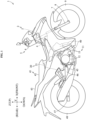
- Fig. 1 is a right side view of a straddled vehicle 1 according to an embodiment.
- the straddled vehicle 1 is classified as, for example, a scooter-type vehicle.
- the straddled vehicle 1 is classified as, for example, a moped vehicle.
- Fig. 1 shows a longitudinal direction X, a transverse direction Y, and an up-down direction Z of the straddled vehicle 1.
- the longitudinal direction X, transverse direction Y, and up-down direction Z are defined with reference to a driver (also called a rider) riding the straddled vehicle 1.
- the longitudinal direction X, transverse direction Y, and up-down direction Z are perpendicular to one another.
- the longitudinal direction X and transverse direction Y are horizontal.
- the up-down direction Z is vertical.
- forward and “rearward” include not only directions parallel to the longitudinal direction X but also directions close to the longitudinal direction X.
- the directions close to the longitudinal direction X are, for example, directions at angles not exceeding 45 degrees to the longitudinal direction X.
- “rightward” and “leftward” include not only directions parallel to the transverse direction Y but also directions close to the transverse direction Y.
- upward and downward include not only directions parallel to the up-down direction Z but also directions close to the up-down direction Z.
- the drawings show the terms FRONT, REAR, UP, DOWN, RIGHT, and LEFT, as appropriate.
- in side view of the straddled vehicle 1 is appropriately referred to as “in vehicle side view”.
- in a plan view of the straddled vehicle 1 is appropriately referred to as “in vehicle plan view”.
- in rear view of the straddled vehicle 1 is appropriately referred to as “in vehicle rear view”.
- the straddled vehicle 1 includes a vehicle body frame 2.
- part of the vehicle body frame 2 is indicated by a broken line.
- the vehicle body frame 2 includes a head pipe 3.
- the head pipe 3 is disposed at a front part of the straddled vehicle 1.
- the vehicle body frame 2 includes a main frame 4.
- the main frame 4 is connected to the head pipe 3.
- the main frame 4 extends rearward from the head pipe 3.
- the straddled vehicle 1 includes a steering device 5 and a front wheel 9.
- the steering device 5 is supported by the vehicle body frame 2.
- the steering device 5 is supported by the head pipe 3.
- the steering device 5 is rotatable with respect to the vehicle body frame 2.
- the front wheel 9 is supported by the steering device 5.
- the steering device 5 includes a handlebar 6, a front suspension 7, and a front axle 8.
- the handlebar 6 is disposed higher than the head pipe 3.
- the front suspension 7 is coupled to the handlebar 6 via a steering shaft (not illustrated).
- the front suspension 7 extends downward from the head pipe 3.
- the front axle 8 is supported by a lower portion of the front suspension 7.
- the front wheel 9 is supported by the front axle 8.
- the front wheel 9 is rotatable about the front axle 8.
- the straddled vehicle 1 includes an engine 11.
- the engine 11 is an internal combustion engine.
- the engine 11 is disposed below the main frame 4.
- the engine 11 is disposed behind the steering device 5.
- the engine 11 is disposed behind the front wheel 9.
- the engine 11 is supported by the vehicle body frame 2.
- the engine 11 is supported by the main frame 4.
- the engine 11 is rigidly supported by the vehicle body frame 2.
- the engine 11 is fixed to the vehicle body frame 2.
- the engine 11 is not swingable with respect to the vehicle body frame 2.
- the engine 11 is not rotatable with respect to the vehicle body frame 2.
- the engine 11 is classified as a rigid mount engine.
- the engine 11 includes a crankcase 12 and a cylinder unit 13.
- the crankcase 12 accommodates a crankshaft (not illustrated).
- the cylinder unit 13 is provided above the crankcase 12.
- the cylinder unit 13 is connected to the crankcase 12.
- the cylinder unit 13 extends upward from the crankcase 12.
- the straddled vehicle 1 includes an intake device 20.
- the intake device 20 is connected to the engine 11.
- the intake device 20 feeds air to the engine 11.
- the intake device 20 is connected to the cylinder unit 13.
- the intake device 20 feeds air to the cylinder unit 13.
- the intake device 20 includes an air cleaner 21.
- the air cleaner 21 is disposed behind the engine 11.
- the air cleaner 21 is disposed behind the crankcase 12.
- the air cleaner 21 is disposed above the crankcase 12. At least a part of the air cleaner 21 is disposed higher than the entire crankcase 12.
- the air cleaner 21 is disposed behind the cylinder unit 13. At least a part of the air cleaner 21 is disposed more rearward than the entire cylinder unit 13.
- the air cleaner 21 is disposed at the same height position as the cylinder unit 13. At least a part of the air cleaner 21 is disposed at the same height position as the cylinder unit 13.
- the air cleaner 21 is disposed behind the front wheel 9.
- the entire air cleaner 21 is disposed more rearward than the entire front wheel 9.
- the straddled vehicle 1 includes an exhaust device 40.
- the exhaust device 40 is connected to the engine 11.
- the exhaust device 40 is connected to the cylinder unit 13.
- the exhaust device 40 conveys exhaust gas of the engine 11.
- the straddled vehicle 1 includes a seat 41.
- the seat 41 is disposed more rearward than the engine 11. At least a part of the seat 41 is disposed more rearward than the entire engine 11.
- the seat 41 is disposed higher than the engine 11.
- the entire seat 41 is disposed higher than the entire engine 11.
- the air cleaner 21 is disposed lower than the seat 41. At least a part of the air cleaner 21 is disposed lower than the entire seat 41.
- the air cleaner 21 is disposed below the seat 41. Although not illustrated, the air cleaner 21 overlaps the seat 41 in vehicle plan view. At least a part of the air cleaner 21 overlaps the seat 41 in vehicle plan view.
- the air cleaner 21 extends to a position more forward than the seat 41.
- the air cleaner 21 has a portion located more forward than the entire seat 41.
- the seat 41 extends to a position more rearward than the air cleaner 21.
- the seat 41 has a portion located more rearward than the entire air cleaner 21.
- the seat 41 includes a first seat 42.
- a driver of the straddled vehicle 1 sits on the first seat 42.
- the air cleaner 21 is disposed below the first seat 42. Although not illustrated, the air cleaner 21 overlaps the first seat 42 in vehicle plan view. At least a part of the air cleaner 21 overlaps the first seat 42 in vehicle plan view.
- the air cleaner 21 extends to a position more forward than the first seat 42.
- the air cleaner 21 has a portion located more forward than the entire first seat 42.
- the first seat 42 extends to a position more rearward than the air cleaner 21.
- the first seat 42 has a portion located more rearward than the entire air cleaner 21.
- the seat 41 includes a second seat 43.
- the second seat 43 is disposed behind the first seat 42.
- the entire second seat 43 is disposed more rearward than the entire first seat 42.
- a passenger of the straddled vehicle 1 sits on the second seat 43.
- the air cleaner 21 is disposed more forward than the second seat 43.
- the entire air cleaner 21 is disposed more forward than the entire second seat 43. Although not illustrated, the air cleaner 21 does not overlap the second seat 43 in vehicle plan view.
- the straddled vehicle 1 includes a pivot shaft 45, a swing arm 46, a rear axle 47, and a rear wheel 48.
- the pivot shaft 45 is disposed behind the engine 11.
- the pivot shaft 45 is disposed behind the crankcase 12.
- the pivot shaft 45 is disposed below the air cleaner 21.
- the pivot shaft 45 is disposed below the seat 41.
- the swing arm 46 is supported by the pivot shaft 45.
- the swing arm 46 is swingable about the pivot shaft 45.
- the swing arm 46 extends rearward from the pivot shaft 45.
- the rear axle 47 is supported by a rear part of the swing arm 46.
- the rear wheel 48 is supported by the rear axle 47.
- the rear wheel 48 is rotatable about the rear axle 47.
- the swing arm 46 and the rear wheel 48 are disposed below the seat 41 in vehicle side view.
- the air cleaner 21 is disposed in front of the rear wheel 48.
- the entire air cleaner 21 is disposed more forward than the entire rear wheel 48.
- the straddled vehicle 1 includes a chain (not illustrated).
- the chain is coupled to the engine 11 and the rear wheel 48.
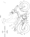
- Fig. 2 is a right side view illustrating the straddled vehicle 1 and a driver T mounting on the straddled vehicle 1.
- the driver T sits on the seat 41.
- the driver T sits on the first seat 42.
- the driver T grips the handlebar 6.
- the driver T has an ear Ta.
- the air cleaner 21 is disposed lower than the ear Ta.
- the entire air cleaner 21 is disposed lower than the entire ear Ta.
- the air cleaner 21 may extend to a position more forward than the ear Ta.
- the air cleaner 21 may have a portion located more forward than the entire ear Ta.
- the air cleaner 21 may extend to a position more rearward than the ear Ta.
- the air cleaner 21 may have a portion located more rearward than the entire ear Ta.
- the air intake device 20 supplies air to the engine 11.
- the engine 11 takes in air from the intake device 20.
- the engine 11 burns fuel with air taken in from the intake device 20 to generate power.
- the chain transmits power from the engine 11 to the rear wheel 48.
- the rear wheel 48 rotates about the rear axle 47.
- the straddled vehicle 1 When the engine 11 operates, the straddled vehicle 1 emits an intake sound. When the engine 11 operates, the intake device 20 emits an intake sound. When the engine 11 operates, the air cleaner 21 emits an intake sound.
- the straddled vehicle 1 gives an intake sound to the driver T.
- the intake sound is transmitted from the intake device 20 to the ear Ta of the driver T.
- the intake sound is transmitted from the air cleaner 21 to the ear Ta of the driver T.
- the driver T listens to the intake sound with the ear Ta.
- Fig. 3 is a right side view of a part of the straddled vehicle 1. The engine 11 will be described.
- the cylinder unit 13 includes a cylinder body 13a, a cylinder head 13b, and a head cover 13c.
- the cylinder head 13b is provided above the cylinder body 13a.
- the head cover 13c is provided above the cylinder head 13b.
- the cylinder body 13a is connected to the crankcase 12.
- the cylinder head 13b is connected to the cylinder body 13a.
- the head cover 13c is connected to the cylinder head 13b.
- the cylinder head 13b is connected to the intake device 20.
- the cylinder head 13b is connected to the exhaust device 40.
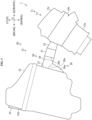
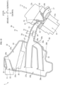
- Fig. 4 is a cross-sectional view of a part of the straddled vehicle 1.
- the engine 11 forms a cylinder hole 14.
- the cylinder hole 14 is a space.
- the cylinder hole 14 accommodates a piston (not illustrated).
- the piston is coupled to the crankshaft described above.
- the cylinder hole 14 is located in the cylinder unit 13.
- the cylinder hole 14 is located in the cylinder body 13a.
- the number of the cylinder holes 14 provided in the engine 11 is one.
- the engine 11 is classified as single cylinder engine.
- the engine 11 forms an intake port 15.
- the intake port 15 is a space.
- the intake port 15 communicates with the cylinder hole 14.
- the intake port 15 is located in the cylinder unit 13.
- the intake port 15 is located in the cylinder head 13b.
- the intake port 15 extends rearward from the cylinder hole 14.
- the intake port 15 extends to the back surface of the cylinder unit 13.
- the intake port 15 extends to the back surface of the cylinder head 13b.
- the intake port 15 is connected to the intake device 20.
- the intake port 15 communicates with the intake device 20.
- the intake port 15 takes in air from the intake device 20.
- the engine 11 includes an intake valve 16.
- the intake valve 16 is provided in the intake port 15.
- the intake valve 16 opens and closes the intake port 15. When the intake valve 16 is closed, the intake port 15 does not communicate with the cylinder hole 14. When the intake valve 16 is closed, the intake port 15 is blocked from the cylinder hole 14. When the intake valve 16 is opened, the intake port 15 communicates with the cylinder hole 14.
- the intake valve 16 is provided in the cylinder unit 13.
- the intake valve 16 is provided in the cylinder head 13b.
- the engine 11 forms an exhaust port 17.
- the exhaust port 17 is a space.
- the exhaust port 17 communicates with the cylinder hole 14.
- the exhaust port 17 is located in the cylinder unit 13.
- the exhaust port 17 is located in the cylinder head 13b.
- the exhaust port 17 extends forward from the cylinder hole 14.
- the exhaust port 17 extends to the front surface of the cylinder unit 13.
- the exhaust port 17 extends to the front surface of the cylinder head 13b.
- the exhaust port 17 is connected to the exhaust device 40.
- the exhaust port 17 communicates with the exhaust device 40.
- the exhaust port 17 discharges exhaust gas to the exhaust device 40.
- the engine 11 includes an exhaust valve 18.
- the exhaust valve 18 is provided in the exhaust port 17.
- the exhaust valve 18 opens and closes the exhaust port 17.
- the exhaust valve 18 is provided in the cylinder unit 13.
- the exhaust valve 18 is provided in the cylinder head 13b.
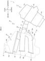
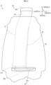
- Fig. 5 is a right side view of a part of the straddled vehicle 1. An outline of the intake device 20 will be described.
- the air cleaner 21 includes an air cleaner case 22.
- the air cleaner case 22 is a substantially closed container.
- the air cleaner case 22 has a substantially box shape. In Fig. 5 , the air cleaner case 22 is indicated by a broken line.
- the air cleaner case 22 forms an internal space 23.
- the internal space 23 is located in the air cleaner case 22.
- the air cleaner 21 includes a filter 24.
- the filter 24 is installed in the air cleaner case 22.
- the filter 24 is installed in the internal space 23.
- the filter 24 partitions the internal space 23 into an upstream space 23a and a downstream space 23b with regard to air flow direction through the filter 24.
- the air cleaner 21 includes an introduction duct 25.
- the introduction duct 25 introduces air into the upstream space 23a from the outside of the air cleaner case 22.
- the introduction duct 25 has one introduction inlet 25a.
- the introduction inlet 25a is disposed outside the air cleaner case 22.
- the introduction inlet 25a is opened to the outside of the air cleaner case 22.
- the introduction duct 25 has one discharge outlet 25b.
- the discharge outlet 25b is disposed in the upstream space 23a.
- the discharge outlet 25b is opened to the upstream space 23a.
- the air cleaner 21 includes an intake pipe 26.
- the intake pipe 26 feeds air from the downstream space 23b to the engine 11.
- the intake pipe 26 feeds air from the downstream space 23b to the intake port 15.
- the intake pipe 26 includes a short pipe 27, a long pipe 28, and a collecting pipe 29.
- the short pipe 27 is opened to the downstream space 23b.
- the long pipe 28 is opened to the downstream space 23b.
- An air flow length of the long pipe 28 is longer than an air flow length of the short pipe 27.
- the collecting pipe 29 is connected to the short pipe 27.
- the collecting pipe 29 is connected to the long pipe 28.
- the collecting pipe 29 collects the short pipe 27 and the long pipe 28.
- the collecting pipe 29 extends toward the engine 11.
- the short pipe 27 has an inlet 27a.
- the inlet 27a is disposed in the downstream space 23b.
- the inlet 27a is opened to the downstream space 23b.
- the long pipe 28 has an inlet 28a.
- the inlet 28a is disposed in the downstream space 23b.
- the inlet 28a is opened to the downstream space 23b.
- the collecting pipe 29 has an outlet 29a.
- the outlet 29a is disposed outside the air cleaner case 22.
- the intake device 20 includes a throttle device 31.
- the throttle device 31 is provided on the intake pipe 26.
- the throttle device 31 opens and closes the intake pipe 26.
- the throttle device 31 is connected to the intake pipe 26.
- the throttle device 31 is connected to the collecting pipe 29.
- the throttle device 31 is connected to the outlet 29a.
- the throttle device 31 includes a throttle body 32 and a throttle valve 34.
- the throttle body 32 is connected to the intake pipe 26.
- the throttle body 32 is connected to the collecting pipe 29.
- the throttle body 32 is connected to the outlet 29a.
- the throttle valve 34 is provided in the throttle body 32.
- the throttle valve 34 opens and closes the throttle body 32.
- the throttle body 32 forms an intake passage 33.
- the intake passage 33 is a space.
- the intake passage 33 is located in the throttle body 32.
- the intake passage 33 communicates with the intake pipe 26.
- the intake passage 33 communicates with the collecting pipe 29.
- the throttle valve 34 is provided in the intake passage 33.
- the throttle valve 34 opens and closes the intake passage 33.
- the intake device 20 includes a connection pipe 35.
- the connection pipe 35 coupled the throttle device 31 and the engine 11.
- connection pipe 35 is connected to the throttle device 31.
- the connection pipe 35 is connected to the throttle body 32.
- the connection pipe 35 communicates with the intake passage 33.
- connection pipe 35 is connected to the engine 11.
- the connection pipe 35 is connected to the cylinder unit 13.
- the connection pipe 35 is connected to the cylinder head 13b.
- the connection pipe 35 is connected to the intake port 15.
- the connection pipe 35 communicates with the intake port 15.
- connection pipe 35 allows the intake passage 33 and the intake port 15 to communicate with each other.
- the intake passage 33 allows the intake pipe 26 and the intake port 15 to communicate with each other.
- the intake pipe 26 does not communicate with the intake port 15.
- the intake pipe 26 is blocked from the intake port 15.
- the intake pipe 26 communicates with the intake port 15.
- the number of the introduction ducts 25 provided in the intake device 20 is one.
- the number of the introduction ducts 25 provided in the intake device 20 is only one.
- the number of the introduction inlets 25a provided in the intake device 20 is one.
- the number of the introduction inlets 25a provided in the intake device 20 is only one.
- the number of the discharge outlets 25b provided in the intake device 20 is one.
- the number of the discharge outlets 25b provided in the intake device 20 is only one.
- the number of the intake pipes 26 provided in the intake device 20 is one.
- the number of the intake pipes 26 provided in the intake device 20 is only one.
- the number of the inlets (27a, 28a) of the intake pipe 26 provided in the intake device 20 is more than one.
- the number of the inlets (27a, 28a) of the intake pipe 26 provided in the intake device 20 is two.
- the number of the outlets (29a) of the intake pipe 26 provided in the intake device 20 is one.
- the number of the outlets (29a) of the intake pipe 26 provided in the intake device 20 is only one.
- the air intake device 20 feeds air to the engine 11.
- a procedure of the operation of the intake device 20 that feeds air to the engine 11 will be described. In other words, the flow of air in the intake device 20 will be described.
- the introduction inlet 25a corresponds to an upstream end of the introduction duct 25.
- the discharge outlet 25b corresponds to a downstream end of the introduction duct 25.
- the filter 24 purifies air.
- the filter 24 removes foreign substances from the air.
- the inlet 27a and the inlet 28a correspond to upstream ends of the intake pipe 26.
- the outlet 29a corresponds to a downstream end of the intake pipe 26.
- Air passes through the throttle body 32. Air passes through the intake passage 33.
- the throttle device 31 adjusts the amount of air flowing through the intake pipe 26.
- the amount of air flowing through the intake pipe 26 corresponds to the amount of intake air of the engine 11.
- the throttle device 31 adjusts an intake amount of intake air of the engine 11.
- the throttle device 31 opens and closes the intake pipe 26.
- the throttle valve 34 opens and closes the throttle body 32.
- the throttle valve 34 opens and closes the intake passage 33.
- the intake device 20 feeds air to the engine 11, the intake device 20 emits an intake sound.
- the air cleaner 21 emits an intake sound.
- the intake device 20 emits an intake sound from one introduction duct 25.
- the intake device 20 emits an intake sound from only one introduction duct 25.
- the intake device 20 emits an intake sound from one introduction inlet 25a.
- the intake device 20 emits an intake sound from only the one introduction inlet 25a.
- the air cleaner case 22 is long in the up-down direction Z. Specifically, the length of the air cleaner case 22 in the up-down direction Z is longer than the length of the air cleaner case 22 in the longitudinal direction X.
- the air cleaner case 22 is disposed behind the engine 11.
- the air cleaner case 22 is disposed behind the cylinder unit 13. At least a part of the air cleaner case 22 is disposed behind the entire cylinder unit 13.
- the air cleaner case 22 is disposed behind the intake port 15. At least a part of the air cleaner case 22 is disposed behind the entire intake port 15.
- the air cleaner case 22 is disposed at the same height position as the cylinder unit 13. At least a part of the air cleaner case 22 is disposed at the same height position as the cylinder unit 13.
- the lower end of the air cleaner case 22 is located higher than the lower end of the cylinder unit 13.
- the lower end of the air cleaner case 22 is located lower than the upper end of the cylinder unit 13.
- the upper end of the air cleaner case 22 is located higher than the upper end of the cylinder unit 13.
- the air cleaner case 22 is disposed at the same height position as the intake port 15. At least a part of the air cleaner case 22 is disposed at the same height position as the intake port 15.
- the air cleaner case 22 extends to a position higher than the intake port 15.
- the air cleaner case 22 includes a portion located higher than the intake port 15.
- the lower end of the air cleaner case 22 is located lower than the lower end of the intake port 15.
- the upper end of the air cleaner case 22 is located higher than the upper end of the intake port 15.
- the entire internal space 23 is formed in the air cleaner case 22.
- the entire filter 24 is disposed in the air cleaner case 22.
- the filter 24 has a plate shape.
- the filter 24 extends in the horizontal direction.
- the filter 24 is disposed higher than the cylinder unit 13. At least a part of the filter 24 is disposed higher than the cylinder unit 13.
- the filter 24 is disposed higher than the intake port 15. At least a part of the filter 24 is disposed higher than the intake port 15.
- the upstream space 23a is located above the filter 24.
- the entire upstream space 23a is located above the entire filter 24.
- the downstream space 23b is located below the filter 24.
- the entire downstream space 23b is located below the entire filter 24.
- the downstream space 23b is disposed below the upstream space 23a.
- the entire downstream space 23b is disposed below the entire upstream space 23a.
- the upstream space 23a is disposed higher than the cylinder unit 13. At least a part of the upstream space 23a is disposed higher than the entire cylinder unit 13.
- the upstream space 23a is disposed higher than the intake port 15. At least a part of the upstream space 23a is disposed higher than the entire intake port 15.
- the downstream space 23b is disposed at the same height position as the cylinder unit 13. At least a part of the downstream space 23b is disposed at the same height position as the cylinder unit 13.
- the downstream space 23b is disposed at the same height position as the intake port 15. At least a part of the downstream space 23b is disposed at the same height position as the intake port 15.
- the introduction duct 25 is long in the longitudinal direction X. Specifically, the length of introduction duct 25 in the longitudinal direction X is longer than the length of the introduction duct 25 in up-down direction Z.
- the introduction duct 25 extends from the introduction inlet 25a to the discharge outlet 25b.
- the introduction duct 25 penetrates the air cleaner case 22.
- the introduction inlet 25a is disposed behind the air cleaner case 22.
- the introduction inlet 25a is disposed more rearward than the entire air cleaner case 22.
- the introduction inlet 25a is disposed more rearward than the back surface of the air cleaner case 22.
- the introduction inlet 25a is opened to an area behind the air cleaner case 22.
- the introduction inlet 25a is disposed behind the upstream space 23a.
- the introduction inlet 25a is disposed more rearward than the entire upstream space 23a.
- the introduction duct 25 extends forward from the introduction inlet 25a.
- the introduction duct 25 penetrates the back surface of the air cleaner case 22.
- the introduction duct 25 is inserted into the upstream space 23a.
- the introduction duct 25 is inserted into the upstream space 23a from the back surface of the air cleaner case 22.
- the introduction duct 25 protrudes rearward from the air cleaner case 22.
- the introduction duct 25 protrudes rearward from the back surface of the air cleaner case 22.
- the introduction inlet 25a is located at the rear end of the introduction duct 25.
- the introduction inlet 25a is opened rearward.
- the discharge outlet 25b is disposed more forward than the introduction inlet 25a.
- the entire discharge outlet 25b is disposed more forward than the entire introduction inlet 25a.
- the discharge outlet 25b is located at a front end of the introduction duct 25.
- the discharge outlet 25b is opened forward.
- the discharge outlet 25b is disposed at the same height position as the introduction inlet 25a. At least a part of the discharge outlet 25b is disposed at the same height position as the introduction inlet 25a.
- the introduction duct 25 extends linearly.
- the introduction duct 25 extends, for example, in the longitudinal direction X.
- the introduction duct 25 is disposed behind the engine 11.
- the introduction duct 25 is disposed behind the cylinder unit 13. At least a part of the introduction duct 25 is disposed more rearward than the entire cylinder unit 13.
- the introduction duct 25 is disposed behind the intake port 15. At least a part of the introduction duct 25 is disposed more rearward than the entire intake port 15.
- the introduction duct 25 is disposed higher than the cylinder unit 13. At least a part of the introduction duct 25 is disposed higher than the entire cylinder unit 13.
- the introduction duct 25 is disposed higher than the intake port 15. At least a part of the introduction duct 25 is disposed higher than the entire intake port 15.
- the introduction inlet 25a is disposed more rearward than the engine 11.
- the introduction inlet 25a is disposed more rearward than the cylinder unit 13. At least a part of the introduction inlet 25a is disposed more rearward than the entire cylinder unit 13.
- the introduction inlet 25a is disposed more rearward than the intake port 15. At least a part of the introduction inlet 25a is disposed more rearward than the entire intake port 15.
- the introduction inlet 25a is disposed higher than the cylinder unit 13. At least a part of the introduction inlet 25a is disposed higher than the entire cylinder unit 13.
- the introduction inlet 25a is disposed higher than the intake port 15. At least a part of the introduction inlet 25a is disposed higher than the entire intake port 15.
- the discharge outlet 25b is disposed behind the engine 11.
- the discharge outlet 25b is disposed behind the cylinder unit 13. At least a part of the discharge outlet 25b is disposed more rearward than the entire cylinder unit 13.
- the discharge outlet 25b is disposed behind the intake port 15. At least a part of the discharge outlet 25b is disposed more rearward than the entire intake port 15.
- the discharge outlet 25b is disposed higher than the cylinder unit 13. At least a part of the discharge outlet 25b is disposed higher than the entire cylinder unit 13.
- the discharge outlet 25b is disposed higher than the intake port 15. At least a part of the discharge outlet 25b is disposed higher than the entire intake port 15.
- the introduction duct 25 is disposed at the same height position as the upstream space 23a. At least a part of the introduction duct 25 is disposed at the same height position as the upstream space 23a.
- the introduction inlet 25a is disposed at the same height position as the upstream space 23a. At least a part of the introduction inlet 25a is disposed at the same height position as the upstream space 23a.
- the introduction duct 25 is disposed higher than the downstream space 23b. At least a part of introduction duct 25 is disposed higher than the entire downstream space 23b.
- the introduction inlet 25a is disposed higher than the downstream space 23b. At least a part of the introduction inlet 25a is disposed higher than the entire downstream space 23b.
- the discharge outlet 25b is disposed higher than the downstream space 23b. At least a part of the discharge outlet 25b is disposed higher than the entire downstream space 23b.
- the introduction duct 25 is disposed higher than the filter 24. At least a part of the introduction duct 25 is disposed higher than the entire filter 24.
- the introduction duct 25 is disposed above the filter 24. Although not illustrated, the introduction duct 25 overlaps the filter 24 in vehicle plan view. At least a part of the introduction duct 25 overlaps the filter 24 in vehicle plan view.
- the introduction inlet 25a is disposed higher than the filter 24. At least a part of the introduction inlet 25a is disposed higher than the entire filter 24.
- the discharge outlet 25b is disposed higher than the filter 24. At least a part of the discharge outlet 25b is disposed higher than the entire filter 24.
- the discharge outlet 25b is disposed above the filter 24. Although not illustrated, the discharge outlet 25b overlaps the filter 24 in vehicle plan view. At least a part of discharge outlet 25b overlaps the filter 24 in vehicle plan view.
- the intake pipe 26 is long in the longitudinal direction X. Specifically, the length of the intake pipe 26 in the longitudinal direction X is longer than the length of the intake pipe 26 in the up-down direction Z.
- the inlet 28a is disposed at the rear end of the intake pipe 26.
- the outlet 29a is disposed at the front end of the intake pipe 26.
- the length of the intake pipe 26 in the longitudinal direction X is a distance between the inlet 28a and the outlet 29a in the longitudinal direction X.
- the intake pipe 26 extends from the inlets 27a and 28a to the outlet 29a.
- the intake pipe 26 penetrates the air cleaner case 22.
- the outlet 29a is disposed in front of the air cleaner case 22.
- the outlet 29a is disposed more forward than the entire air cleaner case 22.
- the outlet 29a is disposed more forward than a front surface of the air cleaner case 22.
- the outlet 29a is disposed in front of the downstream space 23b.
- the outlet 29a is disposed more forward than the entire downstream space 23b.
- the intake pipe 26 extends forward from the downstream space 23b.
- the intake pipe 26 penetrates the front surface of the air cleaner case 22.
- the intake pipe 26 protrudes forward from the air cleaner case 22.
- the intake pipe 26 protrudes forward from the front surface of the air cleaner case 22.
- the intake pipe 26 is inserted into the downstream space 23b.
- the intake pipe 26 is inserted into the downstream space 23b from the front surface of the air cleaner case 22.
- the intake pipe 26 is disposed behind the engine 11.
- the intake pipe 26 extends from the air cleaner case 22 toward the engine 11.
- the intake pipe 26 is disposed behind the cylinder unit 13. At least a part of the intake pipe 26 is disposed more rearward than the entire cylinder unit 13. The intake pipe 26 extends from the air cleaner case 22 toward the cylinder unit 13.
- the intake pipe 26 is disposed behind the intake port 15. At least a part of the intake pipe 26 is disposed more rearward than the entire intake port 15. The intake pipe 26 extends from the air cleaner case 22 toward the intake port 15.
- the intake pipe 26 is disposed at the same height position as the cylinder unit 13. At least a part of the intake pipe 26 is disposed at the same height position as the cylinder unit 13. For example, the entire intake pipe 26 is disposed lower than the upper end of the cylinder unit 13 and higher than the lower end of the cylinder unit 13.
- the intake pipe 26 is disposed at the same height position as the intake port 15. At least a part of the intake pipe 26 is disposed at the same height position as the intake port 15.
- the short pipe 27 extends rearward from the collecting pipe 29.
- the long pipe 28 extends downward from the collecting pipe 29 and then extends rearward.
- the collecting pipe 29 extends forward from the short pipe 27 and the long pipe 28. More precisely, the collecting pipe 29 extends forward and downward from the short pipe 27 and the long pipe 28.
- the short pipe 27 is disposed behind the collecting pipe 29.
- the entire short pipe 27 is disposed more rearward than the entire collecting pipe 29.
- the long pipe 28 is disposed more rearward than the collecting pipe 29.
- the entire long pipe 28 is disposed more rearward than the entire collecting pipe 29.
- the inlet 27a is disposed more rearward than the outlet 29a.
- the entire inlet 27a is disposed more rearward than the entire outlet 29a.
- the inlet 28a is disposed more rearward than the outlet 29a.
- the entire inlet 28a is disposed more rearward than the entire outlet 29a.
- the intake pipe 26 has a joint part 26a.
- the joint part 26a joins the short pipe 27, the long pipe 28, and the collecting pipe 29 to each other.
- the joint part 26a joins the front end of the short pipe 27, the front end of the long pipe 28, and the rear end of the collecting pipe 29 to each other.
- the short pipe 27 extends rearward from the joint part 26a.
- the long pipe 28 extends downward from the joint part 26a and then extends rearward.
- the collecting pipe 29 extends forward from the joint part 26a. More specifically, the collecting pipe 29 extends forward and downward from the joint part 26a.
- the inlet 27a is disposed more rearward than the joint part 26a.
- the entire inlet 27a is disposed more rearward than the entire joint part 26a.
- the inlet 28a is disposed more rearward than the joint part 26a.
- the entire inlet 28a is disposed more rearward than the entire joint part 26a.
- the outlet 29a is disposed more forward than the joint part 26a.
- the entire outlet 29a is disposed more forward than the entire joint part 26a.
- the entire short pipe 27 extends linearly.
- the entire collecting pipe 29 extends linearly.
- the long pipe 28 has a curved portion 30a and a straight portion 30b.
- the curved portion 30a is connected to the short pipe 27 and the collecting pipe 29.
- the curved portion 30a extends downward and rearward from the short pipe 27 and the collecting pipe 29.
- the curved portion 30a has an upper end and a lower end.
- the upper end of the curved portion 30a is joined to the short pipe 27 and the collecting pipe 29.
- the straight portion 30b is connected to the curved portion 30a.
- the straight portion 30b is connected to the lower end of the curved portion 30a.
- the straight portion 30b extends rearward from the curved portion 30a.
- the straight portion 30b extends rearward from the lower end of the curved portion 30a.
- the straight portion 30b extends linearly.
- the straight portion 30b is substantially parallel to the short pipe 27 in vehicle side view.
- the inlet 27a is disposed at the rear end of the short pipe 27.
- the inlet 27a is open rearward.
- the inlet 28a is disposed at the rear end of the long pipe 28.
- the inlet 28a is open rearward.
- the outlet 29a is located at the front end of the collecting pipe 29.
- the long pipe 28 is longer than the short pipe 27.
- the collecting pipe 29 is shorter than the short pipe 27.
- the collecting pipe 29 is shorter than the long pipe 28.
- the inlet 28a is located more rearward than the inlet 27a.
- the entire inlet 28a is located more rearward than the entire inlet 27a.
- the short pipe 27 is located more forward than the inlet 28a.
- the entire short pipe 27 is located more forward than the entire inlet 28a.
- the long pipe 28 extends from a position more rearward than the inlet 27a to a position more forward than the inlet 27a.
- the short pipe 27 is disposed above the long pipe 28.
- the short pipe 27 has a portion located higher than the entire long pipe 28.
- the long pipe 28 is disposed below the short pipe 27.
- the long pipe 28 has a portion located lower than the entire short pipe 27.
- the straight portion 30b is disposed below the short pipe 27. At least a part of the straight portion 30b is disposed lower than the entire short pipe 27.
- the short pipe 27 is disposed higher than the collecting pipe 29.
- the short pipe 27 has a portion located higher than the entire collecting pipe 29.
- the short pipe 27 further has a portion located at the same height position as the collecting pipe 29.
- the collecting pipe 29 is disposed lower than the short pipe 27.
- the collecting pipe 29 has a portion located lower than the entire short pipe 27.
- the long pipe 28 is disposed lower than the collecting pipe 29.
- the long pipe 28 has a portion located lower than the entire collecting pipe 29.
- the long pipe 28 further has a portion located at the same height position as the collecting pipe 29.
- the collecting pipe 29 is disposed higher than the long pipe 28.
- the collecting pipe 29 has a portion disposed higher than the entire long pipe 28.
- the collecting pipe 29 is disposed higher than the straight portion 30b. At least a part of the collecting pipe 29 is disposed higher than the entire straight portion 30b.
- the inlet 27a is located above the inlet 28a. At least a part of the inlet 27a is located higher than the entire inlet 28a.
- the inlet 28a is disposed lower than the inlet 27a. At least a part of the inlet 28a is located lower than the entire inlet 27a.
- the inlet 27a is disposed higher than the outlet 29a.
- the inlet 27a has a portion located higher than the entire outlet 29a.
- the inlet 27a may further have a portion located at the same height position as the outlet 29a.
- the outlet 29a is disposed lower than the inlet 27a.
- the outlet 29a has a portion located lower than the entire inlet 27a.
- the inlet 28a is disposed lower than the outlet 29a. At least a part of the inlet 28a is located lower than the entire outlet 29a.
- the outlet 29a is disposed higher than the inlet 28a. At least a part of the outlet 29a is disposed higher than the entire inlet 28a.
- the short pipe 27 is disposed higher than the inlet 28a. At least a part of the short pipe 27 is disposed higher than the entire inlet 28a. The short pipe 27 is disposed higher than the outlet 29a. The short pipe 27 has a portion located higher than the entire outlet 29a. The short pipe 27 may further have a portion disposed at the same height position as the outlet 29a.
- the long pipe 28 is disposed lower than the inlet 27a. At least a part of the long pipe 28 is located lower than the entire inlet 27a. The long pipe 28 is disposed lower than the outlet 29a. At least a part of the long pipe 28 is disposed lower than the entire outlet 29a.
- the collecting pipe 29 is disposed lower than the inlet 27a.
- the collecting pipe 29 has a portion located lower than the entire inlet 27a.
- the collecting pipe 29 may further have a portion disposed at the same height position as the inlet 27a.
- the collecting pipe 29 is disposed higher than the inlet 28a. At least a part of the collecting pipe 29 is disposed higher than the entire inlet 28a.
- the short pipe 27 has a flow path cross-sectional area.
- the long pipe 28 has a flow path cross-sectional area.
- the collecting pipe 29 has a flow path cross-sectional area.
- the flow path cross-sectional area of the long pipe 28 is smaller than the flow path cross-sectional area of the short pipe 27.
- the flow path cross-sectional area of the collecting pipe 29 is substantially the same as the flow path cross-sectional area of the short pipe 27.
- the flow path cross-sectional area of the collecting pipe 29 is larger than the flow path cross-sectional area of the long pipe 28.
- the flow path cross-sectional area of the short pipe 27 is substantially constant over the extending direction of the short pipe 27.
- the flow path cross-sectional area of the long pipe 28 is substantially constant over the extending direction of the long pipe 28.
- the flow path cross-sectional area of the collecting pipe 29 is substantially constant in the extending direction of the collecting pipe 29.
- the short pipe 27 is a round pipe.
- the long pipe 28 is a round pipe.
- the collecting pipe 29 is a round pipe.
- the short pipe 27 has a diameter.
- the long pipe 28 has a diameter.
- the collecting pipe 29 has a diameter.
- the diameter of the long pipe 28 is smaller than the diameter of the short pipe 27.
- the diameter of the collecting pipe 29 is substantially the same as the diameter of the short pipe 27.
- the diameter of the collecting pipe 29 is larger than the diameter of the long pipe 28.
- the diameter of the short pipe 27 is substantially constant over the extending direction of the short pipe 27.
- the diameter of the long pipe 28 is substantially constant over the extending direction of the long pipe 28.
- the diameter of the collecting pipe 29 is substantially constant over the extending direction of the collecting pipe 29.
- the intake pipe 26 does not include a valve for opening and closing the short pipe 27.
- the short pipe 27 always communicates with the collecting pipe 29.
- the inlet 27a always communicates with the outlet 29a.
- the intake pipe 26 does not include a valve for opening and closing the long pipe 28.
- the long pipe 28 always communicates with the collecting pipe 29.
- the inlet 28a always communicates with the outlet 29a.
- the intake pipe 26 is disposed at the same height position as the air cleaner case 22. At least a part of the intake pipe 26 is disposed at the same height position as the air cleaner case 22. For example, the entire intake pipe 26 is disposed lower than the upper end of the air cleaner case 22 and higher than the lower end of the air cleaner case 22.
- the intake pipe 26 is disposed below the upstream space 23a.
- the entire intake pipe 26 is disposed lower than the entire upstream space 23a.
- the intake pipe 26 is disposed at the same height position as the downstream space 23b. At least a part of the intake pipe 26 is disposed at the same height position as the downstream space 23b.
- At least a part of the joint part 26a may be disposed outside the air cleaner case 22.
- at least a part of the joint part 26a may be disposed in front of the air cleaner case 22.
- At least a part of the joint part 26a may be disposed more forward than the entire air cleaner case 22.
- At least a part of the joint part 26a may be disposed more forward than the front surface of the air cleaner case 22.
- the short pipe 27 is disposed in the downstream space 23b. At least a part of the short pipe 27 is disposed in the downstream space 23b.
- the short pipe 27 may further include a portion located outside the air cleaner case 22.
- the front end of the short pipe 27 may be disposed in front of the air cleaner case 22.
- the front end of the short pipe 27 may be disposed more forward than the entire air cleaner case 22.
- the front end of the short pipe 27 may be disposed more forward than the front surface of the air cleaner case 22.
- the long pipe 28 is disposed in the downstream space 23b. At least a part of the long pipe 28 is disposed in the downstream space 23b.
- the long pipe 28 may further have a portion located outside the air cleaner case 22.
- the front end of the long pipe 28 may be disposed in front of the air cleaner case 22.
- the front end of the long pipe 28 may be disposed more forward than the entire air cleaner case 22.
- the front end of the long pipe 28 may be disposed more forward than the front surface of the air cleaner case 22.
- the curved portion 30a may be disposed in front of the air cleaner case 22. At least a part of the curved portion 30a may be disposed more forward than the entire air cleaner case 22. At least a part of the curved portion 30a may be disposed more forward than the front surface of the air cleaner case 22.
- the collecting pipe 29 is disposed outside the air cleaner case 22. At least a part of the collecting pipe 29 is disposed outside the air cleaner case 22.
- the entire collecting pipe 29 may be disposed outside the air cleaner case 22.
- the entire collecting pipe 29 may be disposed in front of the air cleaner case 22.
- the entire collecting pipe 29 may be disposed more forward than the entire air cleaner case 22.
- the entire collecting pipe 29 may be disposed more forward than the front surface of the air cleaner case 22.
- the intake pipe 26 is disposed lower than the filter 24. At least a part of the intake pipe 26 is disposed lower than the entire filter 24.
- the intake pipe 26 is disposed below the filter 24. Although not illustrated, the intake pipe 26 overlaps the filter 24 in vehicle plan view. At least a part of the intake pipe 26 overlaps the filter 24 in vehicle plan view.
- the short pipe 27 is disposed lower than the filter 24. At least a part of the short pipe 27 is disposed lower than the entire filter 24.
- the short pipe 27 is disposed below the filter 24. Although not illustrated, the short pipe 27 overlaps the filter 24 in vehicle plan view. At least a part of the short pipe 27 overlaps the filter 24 in vehicle plan view.
- the inlet 27a of the short pipe 27 is disposed below the filter 24. Although not illustrated, the inlet 27a overlaps the filter 24 in vehicle plan view. At least a part of the inlet 27a overlaps the filter 24 in vehicle plan view.
- the long pipe 28 is disposed lower than the filter 24. At least a part of the long pipe 28 is disposed lower than the entire filter 24.
- the long pipe 28 is disposed below the filter 24. Although not illustrated, the long pipe 28 overlaps the filter 24 in vehicle plan view. At least a part of the long pipe 28 overlaps the filter 24 in vehicle plan view.
- the inlet 28a of the long pipe 28 is disposed below the filter 24. Although not illustrated, the inlet 28a overlaps the filter 24 in vehicle plan view. At least a part of the inlet 28a overlaps the filter 24 in vehicle plan view.
- the collecting pipe 29 is disposed lower than the filter 24. At least a part of the collecting pipe 29 is disposed lower than the entire filter 24.
- the collecting pipe 29 is disposed more forward than the filter 24.
- the collecting pipe 29 has a portion located more forward than the entire filter 24. Although not illustrated, at least a part of the collecting pipe 29 does not overlap the filter 24 in vehicle plan view.
- the collecting pipe 29 has a portion that does not overlap the filter 24 in vehicle plan view.
- the outlet 29a of the collecting pipe 29 is disposed more forward than the filter 24. At least a part of the outlet 29a is disposed more forward than the entire filter 24. Although not illustrated, the outlet 29a does not overlap the filter 24 in vehicle plan view.
- the intake pipe 26 is disposed lower than the introduction duct 25. At least a part of the intake pipe 26 is disposed lower than the entire introduction duct 25.
- the short pipe 27 is disposed lower than the introduction duct 25. At least a part of the short pipe 27 is disposed lower than the entire introduction duct 25.
- the long pipe 28 is disposed lower than the introduction duct 25. At least a part of the long pipe 28 is disposed lower than the entire introduction duct 25.
- the intake pipe 26 extends from a position more rearward than the introduction duct 25 to a position more forward than the introduction duct 25.
- the intake pipe 26 extends from a position more rearward than the entire introduction duct 25 to a position more forward than the entire introduction duct 25.
- the collecting pipe 29 is disposed more forward than the introduction duct 25.
- the entire collecting pipe 29 is disposed more forward than the entire introduction duct 25.
- the length of the air cleaner case 22 in the longitudinal direction X is longer than the length of the air cleaner case 22 in the transverse direction Y.
- the introduction inlet 25a overlaps the intake pipe 26 in vehicle plan view.
- the introduction inlet 25a is disposed more rearward than the short pipe 27.
- the entire introduction inlet 25a is disposed more rearward than the entire short pipe 27.
- the introduction inlet 25a does not overlap the short pipe 27 in vehicle plan view.
- the introduction inlet 25a is disposed more rearward than the inlet 27a of the short pipe 27.
- the entire introduction inlet 25a is disposed more rearward than the entire inlet 27a.
- the introduction inlet 25a does not overlap the inlet 27a in vehicle plan view.
- the introduction inlet 25a overlaps the long pipe 28 in vehicle plan view.
- the introduction inlet 25a overlaps the inlet 28a of the long pipe 28 in vehicle plan view. A part of the introduction inlet 25a overlaps the inlet 28a in vehicle plan view.
- the intake pipe 26 overlaps the air cleaner case 22 in vehicle plan view. A part of the intake pipe 26 overlaps the air cleaner case 22 in vehicle plan view.
- the short pipe 27 overlaps the air cleaner case 22 in vehicle plan view.
- the inlet 27a overlaps the air cleaner case 22 in vehicle plan view.
- the entire inlet 27a overlaps the air cleaner case 22 in vehicle plan view.
- the long pipe 28 overlaps the air cleaner case 22 in vehicle plan view.
- the inlet 28a overlaps the air cleaner case 22 in vehicle plan view.
- the entire inlet 28a overlaps the air cleaner case 22 in vehicle plan view.
- the collecting pipe 29 does not overlap the air cleaner case 22 in vehicle plan view.
- the collecting pipe 29 has a portion that does not overlap the air cleaner case 22 in vehicle plan view.
- the outlet 29a does not overlap the air cleaner case 22 in vehicle plan view.
- Fig. 7 is a plan view of the air cleaner 21.
- the air cleaner case 22 and the introduction duct 25 are indicated by broken lines. More specifically, the introduction duct 25 is indicated by an alternate long and short dash line.
- illustrations of the filter 24 are omitted.
- the introduction duct 25 overlaps the air cleaner case 22 in vehicle plan view.
- the entire introduction duct 25 overlaps the air cleaner case 22 in vehicle plan view.
- At least a part of the intake pipe 26 is disposed more leftward than the right end of the introduction duct 25 and more rightward than the left end of the introduction duct 25.
- the intake pipe 26 overlaps the introduction duct 25 in vehicle plan view.
- At least a part of the short pipe 27 is disposed more leftward than the right end of the introduction duct 25 and more rightward than the left end of the introduction duct 25.
- the short pipe 27 overlaps the introduction duct 25 in vehicle plan view.
- At least a part of the long pipe 28 is disposed more leftward than the right end of the introduction duct 25 and more rightward than the left end of the introduction duct 25.
- the long pipe 28 overlaps the introduction duct 25 in vehicle plan view.
- At least a part of the collecting pipe 29 is disposed more leftward than the right end of the introduction duct 25 and more rightward than the left end of the introduction duct 25.
- the collecting pipe 29 does not overlap the introduction duct 25 in vehicle plan view.
- the collecting pipe 29 is disposed in front of the introduction duct 25 in vehicle plan view.
- the long pipe 28 overlaps the short pipe 27 in vehicle plan view. At least a part of the long pipe 28 overlaps the short pipe 27 in vehicle plan view.
- a portion of the long pipe 28 overlapping the short pipe 27 in vehicle plan view is defined as an overlapping portion of the long pipe 28.
- the overlapping portion of the long pipe 28 overlaps the introduction duct 25 in vehicle plan view.
- Part of the overlapping portion of the long pipe 28 overlaps the introduction duct 25 in vehicle plan view.
- the collecting pipe 29 does not overlap the short pipe 27 in vehicle plan view.
- the collecting pipe 29 does not overlap the long pipe 28 in vehicle plan view.
- Fig. 8 is a rear view of the air cleaner 21.
- the filter 24 is indicated by a broken line.
- the length of the air cleaner case 22 in the up-down direction Z is longer than the length of the air cleaner case 22 in the transverse direction Y.
- the introduction duct 25 is a square pipe.
- the introduction duct 25 overlaps the air cleaner case 22 in vehicle rear view.
- the entire introduction duct 25 overlaps the air cleaner case 22 in vehicle rear view.
- the inlet 27a does not overlap the filter 24 in vehicle rear view.
- the inlet 27a is disposed below the filter 24 in vehicle rear view.
- At least a part of the outlet 29a is disposed more leftward than the right end of the inlet 28a and more rightward than the left end of the inlet 28a.
- the throttle device 31 is disposed behind the intake port 15. At least a part of the throttle device 31 is disposed more rearward than the entire intake port 15.
- the throttle device 31 is disposed at the same height position as the cylinder unit 13. At least a part of the throttle device 31 is disposed at the same height position as the cylinder unit 13.
- the throttle device 31 is disposed outside the air cleaner case 22.
- the entire throttle device 31 is disposed outside the air cleaner case 22.
- the throttle device 31 is disposed at the same height position as the air cleaner case 22.
- the entire throttle device 31 is disposed at the same height position as the air cleaner case 22.
- the throttle device 31 is disposed lower than the upstream space 23a.
- the entire throttle device 31 is disposed lower than the upstream space 23a.
- the throttle device 31 is disposed at the same height position as the downstream space 23b. At least a part of the throttle device 31 is disposed at the same height position as the downstream space 23b.
- the throttle device 31 is disposed lower than the filter 24.
- the entire throttle device 31 is disposed lower than the filter 24.
- the throttle device 31 is disposed in front of the intake pipe 26. At least a part of the throttle device 31 is disposed more forward than the entire intake pipe 26.
- the throttle device 31 is disposed at the same height position as the intake pipe 26. At least a part of the throttle device 31 is disposed at the same height position as the intake pipe 26.
- connection pipe 35 extends linearly.
- the connection pipe 35 extends in the longitudinal direction X.
- connection pipe 35 is disposed behind the cylinder unit 13. At least a part of the connection pipe 35 is disposed behind the entire cylinder unit 13.
- connection pipe 35 is disposed in front of the throttle device 31. At least a part of the connection pipe 35 is disposed in front of the entire throttle device 31.
- An intake sound when the engine 11 operates at 4000 rpm is defined as "first intake sound”.
- the intake sound when the engine 11 operates at 6000 rpm is defined as “second intake sound”.
- the intake sound when the engine 11 operates at 8000 rpm is defined as "third intake sound”.
- the first intake sound illustrated in Fig. 9 is a measurement value of the first intake sound.
- the second intake sound illustrated in Fig. 10 is a measurement value of the second intake sound.
- the third intake sound illustrated in Fig. 11 is a measurement value of the third intake sound.
- the first intake sound, the second intake sound, and the third intake sound were measured at a position above the straddled vehicle 1. Specifically, the first intake sound, the second intake sound, and the third intake sound were measured at the position of the ear Ta of the driver T who mounts on the straddled vehicle 1.
- the first intake sound, the second intake sound, and the third intake sound were measured by, for example, a microphone.
- the microphone is installed at the position of the ear Ta of the driver T who mounts on the straddled vehicle 1.
- the horizontal axis represents the frequency [Hz].
- the vertical axis represents the sound pressure level [dB].
- the sound pressure level increases toward the upward direction along the vertical axis.
- the sound pressure level is an index indicating the loudness of sound.
- the relationship between the frequency and the sound pressure level includes the sound pressure level for each frequency.
- the first intake sound corresponds to synthesis of sound pressure levels for each frequency illustrated in Fig. 9 .
- the second intake sound corresponds to synthesis of sound pressure levels for each frequency illustrated in Fig. 10 .
- the third intake sound corresponds to synthesis of sound pressure levels for each frequency illustrated in Fig. 11 .
- the high-frequency range is a range of frequencies.
- the high-frequency range is higher than the middle-frequency range.
- the high-frequency range is a frequency range of 400 Hz or more and less than 800 Hz.
- the high-frequency range is more preferably a frequency range of 500 Hz or more and less than 800 Hz.
- the low-frequency range is a range of frequencies.
- the low-frequency range is lower than the middle-frequency range.
- the low-frequency range is a frequency range of 0 Hz or more and less than 200 Hz.
- the ultrahigh-frequency range is a range of frequencies.
- the ultrahigh-frequency range is higher than the high-frequency range.
- the ultrahigh-frequency range is a frequency range of 800 Hz or more and 1000 Hz or less.
- the intake sound includes a middle-frequency range component and a high-frequency range component.
- the middle-frequency range component is easily heard by the driver T of the straddled vehicle 1.
- the high-frequency range component is easily heard by the driver T.
- the intake sound includes a low-frequency range component and an ultrahigh-frequency range component.
- the low-frequency range component is less audible to the driver T than the low-frequency range component and the high-frequency range component.
- the ultrahigh-frequency range component is less audible to the driver T than the low-frequency range component and the high-frequency range component.
- the middle-frequency range component is more easily heard by the driver T than the low-frequency range component and the ultrahigh-frequency range component.
- the high-frequency range component is more easily heard by the driver T than the low-frequency range component and the ultrahigh-frequency range component.
- the "low-frequency range component” is referred to as “low component”.
- a “middle-frequency range component” is referred to as “middle component”.
- the "high-frequency range component” is referred to as “high component”.
- the “ultrahigh-frequency range component” is referred to as “ultrahigh component”.
- the first intake sound includes a middle component. Specifically, the first intake sound includes a sound pressure level for each frequency in the middle-frequency range.
- the first intake sound includes a first maximum sound pressure level M1.
- the first maximum sound pressure level M1 is a maximum value among sound pressure levels for each frequency of the first intake sound in the middle-frequency range.
- the first maximum sound pressure level M1 is included in the middle component of the first intake sound.
- the frequency is 263 Hz.
- the first maximum sound pressure level M1 is a sound pressure level at 263 Hz in the first intake sound.
- the middle-frequency range is defined as a frequency range of 200 Hz or more and less than 400 Hz
- 263 Hz is in the middle-frequency range.
- the middle-frequency range is defined as a frequency range of 250 Hz or more and less than 400 Hz
- 263 Hz is in the middle-frequency range.
- the sound pressure level of 263 Hz is included in the middle component.
- the first intake sound includes a high component. Specifically, the first intake sound includes a sound pressure level for each frequency in the high-frequency range.
- the first intake sound includes a second maximum sound pressure level M2.
- the second maximum sound pressure level M2 is the maximum value among the sound pressure levels for each frequency of the first intake sound in the high-frequency range.
- the second maximum sound pressure level M2 is included in the high component of the first intake sound.
- the frequency is 538 Hz.
- the second maximum sound pressure level M2 is a sound pressure level at 538 Hz in the first intake sound.
- the high-frequency range is defined as a frequency range of 400 Hz or more and less than 800 Hz
- 538 Hz is in the high-frequency range.
- the high-frequency range is defined as a frequency range of 500 Hz or more and less than 800 Hz
- 538 Hz is in the high-frequency range.
- the sound pressure level of 538 Hz is included in the high component.
- the first intake sound includes a low component. Specifically, the first intake sound includes a sound pressure level for each frequency in the low-frequency range.
- the first intake sound includes a fifth maximum sound pressure level M5.
- the fifth maximum sound pressure level M5 is the maximum value among the sound pressure levels for each frequency of the first intake sound in the low-frequency range.
- the fifth maximum sound pressure level M5 is included in the low component of the first intake sound.
- the frequency is 100 Hz.
- the fifth maximum sound pressure level M5 is a sound pressure level at 100 Hz in the first intake sound. 100 Hz is in the low-frequency range. The sound pressure level of 100 Hz is included in the low component.
- the first intake sound includes an ultrahigh component. Specifically, the first intake sound includes a sound pressure level for each frequency in the ultrahigh-frequency range.
- the first intake sound includes a sixth maximum sound pressure level M6.
- the sixth maximum sound pressure level M6 is the maximum value among the sound pressure levels for each frequency of the first intake sound in the ultrahigh-frequency range.
- the sixth maximum sound pressure level M6 is included in the ultrahigh component of the first intake sound.
- the frequency is 800 Hz.
- the sixth maximum sound pressure level M6 is a sound pressure level at 800 Hz in the first intake sound. 800 Hz is in the ultrahigh-frequency range. The sound pressure level of 800 Hz is included in the ultrahigh component.
- the second maximum sound pressure level M2 is larger than the fifth maximum sound pressure level M5.
- the second maximum sound pressure level M2 is larger than the sixth maximum sound pressure level M6.
- the second intake sound includes eighteen peaks D1 to D18.
- the peaks from D1 to D18 are arranged in this order.
- the peaks from D1 to D18 are arranged in this order along the axis of frequency.
- the peak D1 and the peak D3 are adjacent to the peak D2 along the axis of frequency.
- the peak frequencies E8 to E15 are in the high-frequency range. That is, when the high-frequency range is defined as a frequency range of 400 Hz or more and less than 800 Hz, the peaks D8 to D15 are in the high-frequency range. Therefore, the sound pressure levels F8 to F15 are included in the high component.
- the sound pressure level F6 is the largest among the sound pressure levels F4 to F7.
- the sound pressure level F6 is the largest among the sound pressure levels F5 to F7.
- the third maximum sound pressure level M3 described above is the sound pressure level F6 of the peak D6.
- the peak frequency E6 of the peak D6 is 300 Hz.
- the sound pressure level F15 is the largest among the sound pressure levels F8 to F15.
- the sound pressure level F15 is the largest among the sound pressure levels F10 to F15.
- the fourth maximum sound pressure level M4 described above is the sound pressure level F15 of the peak D15.
- the peak frequency E15 of the peak D15 is 750 Hz.
- the sound pressure level F16 is the largest among the sound pressure levels F16 to F18.
- the above-described eighth maximum sound pressure level M8 is the sound pressure level F16 of the peak D16.
- the peak frequency E16 of the peak D16 is 800 Hz.
- the peak D6 is defined as "third peak D6".
- the peaks D5 and D7 are defined as “third adjacent peak (D5, D7)”.
- the second intake sound includes a third peak D6 and a third adjacent peak (D5, D7) with respect to a sound pressure level for each frequency.
- the third maximum sound pressure level M3 is the sound pressure level F6 of the third peak D6.
- the third adjacent peak (D5, D7) is adjacent to the third peak D6 along the frequency axis.
- a difference between the third maximum sound pressure level M3 and the sound pressure level (F5, F7) of the third adjacent peak (D5, D7) is defined as a third difference S3.
- the third difference S3 is preferably 3 dB or more.
- the third adjacent peak (D5, D7) includes a third low adjacent peak D5.
- a difference between the third maximum sound pressure level M3 and the sound pressure level F5 of the third low adjacent peak D5 is defined as a third low difference S3L.
- the third low difference S3L is preferably 3 dB or more.
- the third low adjacent peak D5 will be described.
- the third low adjacent peak D5 is at the peak frequency E5.
- the third peak D6 is at the peak frequency E6.
- the peak frequency E5 is close to the peak frequency E6 and lower than the peak frequency E6.
- the peak frequency E5 is closest to the peak frequency E6 among the peak frequencies E1 to E5 lower than the peak frequency E6.
- the third adjacent peak (D5, D7) includes a third high adjacent peak D7.
- a difference between the third maximum sound pressure level M3 and the sound pressure level F7 of the third high adjacent peak D7 is defined as a third high difference S3H.
- the third high difference S3H is preferably 3 dB or more.
- the third high adjacent peak D7 will be described.
- the third peak D6 is at the peak frequency E6.
- the third high adjacent peak D7 is at the peak frequency E7.
- the peak frequency E7 is close to the peak frequency E6 and higher than the peak frequency E6.
- the peak frequency E7 is closest to the peak frequency B6 among the peak frequencies E7 to E18 higher than the peak frequency E6.
- the peak D15 is referred to as "fourth peak D15".
- the peaks D14 and D16 are defined as “fourth adjacent peak (D14, D16)”.
- the second intake sound includes a fourth peak D15 and a fourth adjacent peak (D14, D16) with respect to a sound pressure level for each frequency.
- the fourth maximum sound pressure level M4 is the sound pressure level F15 of the fourth peak D15.
- the fourth adjacent peak (D14, D16) is adjacent to the fourth peak D15 along the frequency axis.
- a difference between the fourth maximum sound pressure level M4 and the sound pressure level (F14, F16) of the fourth adjacent peak (D14, D16) is defined as a fourth difference S4.
- the fourth difference S4 is preferably 3 dB or more.
- the fourth adjacent peak (D14, D16) includes a fourth low adjacent peak D14.
- a difference between the fourth maximum sound pressure level M4 and the sound pressure level F14 of the fourth low adjacent peak D14 is defined as a fourth low difference S4L.
- the fourth low difference S4L is preferably 3 dB or more.
- the fourth low adjacent peak D14 will be described.
- the fourth low adjacent peak D14 is at the peak frequency E14.
- the fourth peak D15 is at the peak frequency E15.
- the peak frequency E14 is close to the peak frequency E15 and lower than the peak frequency E15.
- the peak frequency E14 is closest to the peak frequency E15 among the peak frequencies E1 to E14 lower than the peak frequency E15.
- the fourth adjacent peak (D14, D16) includes a fourth high adjacent peak D16.
- a difference between the fourth maximum sound pressure level M4 and the sound pressure level F16 of the fourth high adjacent peak D16 is defined as a fourth high difference S4H.
- the fourth high difference S4H is preferably 3 dB or more.
- the fourth high adjacent peak D16 will be described.
- the fourth peak D15 is at the peak frequency E15.
- the fourth high adjacent peak D16 is at the peak frequency E16.
- the peak frequency E16 is close to the peak frequency E15 and higher than the peak frequency E15.
- the peak frequency E16 is the closest to the peak frequency E15 among the peak frequencies E16 to E18 higher than the peak frequency E15.
- the third intake sound includes a middle component. Specifically, the third intake sound includes a sound pressure level for each frequency in the middle-frequency range.
- the third intake sound includes a ninth maximum sound pressure level M9.
- the ninth maximum sound pressure level M9 is the maximum value among the sound pressure levels for each frequency of the third intake sound in the middle-frequency range.
- the ninth maximum sound pressure level M9 is included in the middle component of the third intake sound.
- the frequency is 338 Hz.
- the ninth maximum sound pressure level M9 is a sound pressure level at 338 Hz in the third intake sound.
- the middle-frequency range is defined as a frequency range of 200 Hz or more and less than 400 Hz
- 338 Hz is in the middle-frequency range.
- the middle-frequency range is defined as a frequency range of 250 Hz or more and less than 400 Hz
- 338 Hz is in the middle-frequency range.
- the sound pressure level of 338 Hz is included in the middle component.
- the third intake sound includes a high component. Specifically, the third intake sound includes a sound pressure level for each frequency in the high-frequency range.
- the third intake sound includes a tenth maximum sound pressure level M10.
- the tenth maximum sound pressure level M10 is the maximum value among the sound pressure levels for each frequency of the third intake sound in the high-frequency range.
- the tenth maximum sound pressure level M10 is included in the high component of the third intake sound.
- the frequency is 600 Hz.
- the tenth maximum sound pressure level M10 is a sound pressure level at 600 Hz in the third intake sound.
- the high-frequency range is defined as a frequency range of 400 Hz or more and less than 800 Hz
- 600 Hz is in the high-frequency range.
- the high-frequency range is defined as frequency range of 500 Hz or more and less than 800 Hz
- 600 Hz is in the high-frequency range.
- the sound pressure level of 600 Hz is included in the high component.
- the third intake sound includes a low component. Specifically, the third intake sound includes a sound pressure level for each frequency in the low-frequency range.
- the third intake sound includes an eleventh maximum sound pressure level M11.
- the eleventh maximum sound pressure level M11 is the maximum value among the sound pressure levels for each frequency of the third intake sound in the low-frequency range.
- the eleventh maximum sound pressure level M11 is included in the low component of the third intake sound.
- the frequency is 138 Hz.
- the eleventh maximum sound pressure level M11 is a sound pressure level at 138 Hz in the third intake sound.
- 138 Hz is in the low-frequency range.
- the sound pressure level of 138 Hz is included in the low component.
- the third intake sound includes an ultrahigh component. Specifically, the third intake sound includes a sound pressure level for each frequency in the ultrahigh-frequency range.
- the third intake sound includes a twelfth maximum sound pressure level M12.
- the twelfth maximum sound pressure level M12 is the maximum value among the sound pressure levels for each frequency of the third intake sound in the ultrahigh-frequency range.
- the twelfth maximum sound pressure level M12 is included in the ultrahigh component of the third intake sound.
- the frequency is 800 Hz.
- the twelfth maximum sound pressure level M12 is a sound pressure level at 800 Hz in the third intake sound. 800 Hz is in the ultrahigh-frequency range. The sound pressure level of 800 Hz is included in the ultrahigh component.
- the ninth maximum sound pressure level M9 is larger than the eleventh maximum sound pressure level M11.
- the ninth maximum sound pressure level M9 is larger than the twelfth maximum sound pressure level M12.
- the tenth maximum sound pressure level M10 is larger than the eleventh maximum sound pressure level M11.
- the tenth maximum sound pressure level M10 is larger than the twelfth maximum sound pressure level M12.
- the ninth maximum sound pressure level M9 is 95 dB.
- the tenth maximum sound pressure level M10 is 97 dB.
- the eleventh maximum sound pressure level M11 is 82 dB.
- the twelfth maximum sound pressure level M12 is 83 dB.
- the third intake sound will be described in more detail.
- the sound pressure level for each frequency of the third intake sound pulsates as the frequency increases. That is, the third intake sound includes a plurality of peaks G with respect to the sound pressure level for each frequency.
- Each peak G is a positive peak.
- the positive peak is a peak convex upward in the relationship between the frequency and the sound pressure level representing the third intake sound.
- the positive peak is a position where the sound pressure level for each frequency locally becomes maximum.
- the third intake sound includes fifteen peaks G1 to G15.
- the peaks from G1 to G15 are arranged in this order.
- the peaks from G1 to G15 are arranged in this order along the axis of frequency.
- the peak G1 and the peak G3 are adjacent to the peak G2 along the axis of frequency.
- the frequency of the peak G1 is defined as a peak frequency H1.
- the frequencies of the peaks G2 to G15 are defined as peak frequencies H2 to H15.
- Fig. 11 shows peak frequencies H1 to H3. In Fig. 11 , illustrations of the peak frequencies H4 to H15 are not omitted.
- the peak frequency Hn is larger than the peak frequency H(n-1).
- n is an integer from 2 to 15.
- the peak frequency H2 is larger than the peak frequency H1.
- the peak frequency H3 is larger than the peak frequency H2.
- the sound pressure level of the peak G1 is defined as a sound pressure level J1.
- the sound pressure levels of the peaks G2 to G15 are defined as sound pressure levels J2 to J15.
- Fig. 11 illustrates sound pressure levels J1 to J3. In Fig. 11 , illustrations of the sound pressure levels J4 to J15 are omitted.
- the sound pressure level J1 is a maximum value of the sound pressure level in the vicinity of the peak frequency H1.
- the sound pressure level J2 is a maximum value of the sound pressure level in the vicinity of the peak frequency H2.
- the peak frequencies H1 to H2 are in a low-frequency range. That is, the peaks G1 to G2 are in low-frequency range. Therefore, the sound pressure levels J1 to J2 are included in the low component.
- the middle-frequency range is defined as a frequency range of 200 Hz or more and less than 400 Hz
- the peak frequencies H3 to H5 are in the middle-frequency range. That is, the peaks G3 to G5 are in the middle-frequency range. Therefore, the sound pressure levels J3 to J5 are included in the middle component.
- the middle-frequency range is defined as a frequency range of 250 Hz or more and less than 400 Hz
- the peak frequencies H4 to H5 are in the middle-frequency range. That is, the peaks G4 to G5 are in the middle-frequency range. Therefore, the sound pressure levels J4 to J5 are included in the middle component.
- the high-frequency range is defined as a frequency range of 400 Hz or more and less than 800 Hz
- the peak frequencies H6 to H11 are in the high-frequency range. That is, the peaks G6 to G11 are in the high-frequency range. Therefore, the sound pressure levels J6 to J11 are included in the high component.
- the high-frequency range is defined as a frequency range of 500 Hz or more and less than 800 Hz
- the peak frequencies H8 to H11 are in the high-frequency range. That is, the peaks G8 to G11 are in the high-frequency range. Therefore, the sound pressure levels J8 to J11 are included in the high component.
- the peak frequencies H12 to H15 is in the ultrahigh-frequency range. That is, the peaks G12 to G15 are in the ultrahigh-frequency range. Therefore, the sound pressure levels J12 to J15 are included in the ultrahigh component.
- the sound pressure level J2 is the largest of the sound pressure levels J1 to J2.
- the above-described eleventh maximum sound pressure level M11 is the sound pressure level J2 of the peak G2.
- the peak frequency H2 of the peak G2 is 138 Hz.
- the sound pressure level J5 is the largest among the sound pressure levels J3 to J5.
- the sound pressure level J5 is the largest among the sound pressure levels J4 to J5.
- the ninth maximum sound pressure level M9 described above is the sound pressure level J5 of the peak G5.
- the peak frequency H5 of the peak G5 is 338 Hz.
- the sound pressure level J9 is the largest among the sound pressure levels J6 to J11.
- the sound pressure level J9 is the largest among the sound pressure levels J8 to J11.
- the above-described tenth maximum sound pressure level M10 is the sound pressure level J9 of the peak G9.
- the peak frequency H9 of the peak G9 is 600 Hz.
- the sound pressure level J12 is the largest among the sound pressure levels J12 to J15.
- the above-described twelfth maximum sound pressure level M12 is the sound pressure level J12 of the peak G12.
- the peak frequency H12 of the peak G12 is 800 Hz.
- the peak G5 is referred to as "ninth peak G5".
- the peaks G4 and G6 are referred to as “ninth adjacent peak (G4, G6)".
- the third intake sound includes a ninth peak G5 and a ninth adjacent peak (G4, G6) with respect to a sound pressure level for each frequency.
- the ninth maximum sound pressure level M9 is the sound pressure level J9 of the ninth peak G5.
- the ninth adjacent peak (G4, G6) is adjacent to the ninth peak G5 along the frequency axis.
- a difference between the ninth maximum sound pressure level M9 and the sound pressure level (J4, J6) of the ninth adjacent peak (G4, G6) is defined as a ninth difference S9.
- the ninth difference S9 is preferably 3 dB or more.
- the ninth adjacent peak (G4, G6) includes the ninth low adjacent peak G4.
- a difference between the ninth maximum sound pressure level M9 and the sound pressure level J4 of the ninth low adjacent peak G4 is defined as a ninth low difference S9L.
- the ninth low difference S9L is preferably 3 dB or more.
- the ninth low adjacent peak G4 will be described.
- the ninth low adjacent peak G4 is at the peak frequency H4.
- the ninth peak G5 is at the peak frequency H5.
- the peak frequency H4 is close to the peak frequency H5 and lower than the peak frequency H5.
- the peak frequency H4 is closest to the peak frequency H5 among the peak frequencies H1 to H4 lower than the peak frequency H5.
- the ninth adjacent peak (G4, G6) includes the ninth high adjacent peak G6.
- a difference between the ninth maximum sound pressure level M9 and the sound pressure level J6 of the ninth high adjacent peak G6 is defined as a ninth high difference S9H.
- the ninth high difference S9H is preferably 3 dB or more.
- the ninth high adjacent peak G6 will be described.
- the ninth peak G5 is at the peak frequency H5.
- the ninth high adjacent peak G6 is at the peak frequency H6.
- the peak frequency H6 is close to the peak frequency H5 and higher than the peak frequency H5.
- the peak frequency H6 is closest to the peak frequency H5 among the peak frequencies H6 to H15 higher than the peak frequency H5.
- the peak G9 is defined as "tenth peak G9".
- the peaks G8 and G10 are defined as “tenth adjacent peak (G8, G10)”.
- the third intake sound includes a tenth peak G9 and a tenth adjacent peak (G8, G10) with respect to the sound pressure level for each frequency.
- the tenth maximum sound pressure level M10 is the sound pressure level J9 of the tenth peak G9.
- the tenth adjacent peak (G8, G10) is adjacent to the tenth peak G9 along the frequency axis.
- a difference between the tenth maximum sound pressure level M10 and the sound pressure level (J8, J10) of the tenth adjacent peak (G8, G10) is defined as a tenth difference S10.
- the tenth difference S10 is preferably 3 dB or more.
- the tenth adjacent peak (G8, G10) includes the tenth low adjacent peak G8.
- a difference between the tenth maximum sound pressure level M10 and the sound pressure level J8 of the tenth low adjacent peak G8 is defined as a tenth low difference S10L.
- the tenth low difference S10L is preferably 3 dB or more.
- the tenth low adjacent peak G8 will be described.
- the tenth lower adjacent peak G8 is at the peak frequency H8.
- the tenth peak G9 is at the peak frequency H9.
- the peak frequency H8 is close to the peak frequency H9 and lower than the peak frequency H9.
- the peak frequency H8 is closest to the peak frequency H9 among the peak frequencies H1 to H8 lower than the peak frequency H9.
- the tenth adjacent peak (G8, G10) includes the tenth high adjacent peak G10.
- a difference between the tenth maximum sound pressure level M10 and the sound pressure level J10 of the tenth high adjacent peak G10 is defined as a tenth high difference S10H.
- the tenth high difference S10H is preferably 3 dB or more.
- the tenth high adjacent peak G10 will be described.
- the tenth peak G9 is at the peak frequency H9.
- the tenth high adjacent peak G10 is at the peak frequency H10.
- the peak frequency H10 is close to the peak frequency H9 and higher than the peak frequency H9.
- the peak frequency H10 is closest to the peak frequency H9 among the peak frequencies H10 to H15 higher than the peak frequency H9.
- the low-frequency range is the frequency range.
- the low-frequency range is lower than the middle-frequency range.
- the low-frequency range is the frequency range of 0 Hz or more and less than 200 Hz.
- the intake sound includes the low-frequency range component. That is, the intake sound includes the low component.
- the first intake sound includes the fifth maximum sound pressure level M5 and the sixth maximum sound pressure level M6.
- the fifth maximum sound pressure level M5 is the maximum value of the sound pressure level of the first intake sound in the low-frequency range. More specifically, the fifth maximum sound pressure level M5 is the maximum value among the sound pressure levels for each frequency of the first intake sound in the low-frequency range.
- the sixth maximum sound pressure level M6 is the maximum value of the sound pressure level of the first intake sound in the ultrahigh-frequency range. More specifically, the sixth maximum sound pressure level M6 is the maximum value among the sound pressure levels for each frequency of the first intake sound in the ultrahigh-frequency range.
- the second intake sound includes the seventh maximum sound pressure level M7 and the eighth maximum sound pressure level M8.
- the seventh maximum sound pressure level M7 is the maximum value of the sound pressure level of the second intake sound in the low-frequency range. More specifically, the seventh maximum sound pressure level M7 is the maximum value among the sound pressure levels for each frequency of the second intake sound in the low-frequency range.
- the eighth maximum sound pressure level M8 is the maximum value of the sound pressure level of the second intake sound in the ultrahigh-frequency range. More specifically, the eighth maximum sound pressure level M8 is the maximum value among the sound pressure levels for each frequency of the second intake sound in the ultrahigh-frequency range.
- the third maximum sound pressure level M3 is larger than the seventh maximum sound pressure level M7.
- the third maximum sound pressure level M3 is larger than the eighth maximum sound pressure level M8.
- the fourth maximum sound pressure level M4 is larger than the seventh maximum sound pressure level M7.
- the fourth maximum sound pressure level M4 is larger than the eighth maximum sound pressure level M8. Therefore, the middle component of the second intake sound is larger than the low component of the second intake sound and the ultrahigh component of the second intake sound.
- the high component of the second intake sound is larger than the low component of the second intake sound and the ultrahigh component of the second intake sound. Therefore, the middle component of the second intake sound is emphasized more than the low component of the second intake sound and the ultrahigh component of the second intake sound.
- the high component of the second intake sound is emphasized more than the low component of the second intake sound and the ultrahigh component of the second intake sound.
- the middle component and the high component are more easily heard by the driver T than the low component and the ultrahigh component.
- the relationship between the middle component and the high component is close to the relationship between the fundamental tone and the first overtone.
- the middle component of the second intake sound and the high component of the second intake sound are emphasized more than the low component of the second intake sound and the ultrahigh component of the second intake sound. Therefore, the second intake sound is more comfortable for the driver T. Therefore, the second intake sound effectively gives the driver T a sense of elation.
- the intake sound when the engine 11 operates at 8000 rpm is defined as third intake sound.
- the third intake sound is represented by the relationship between the frequency and the sound pressure level.
- the middle component and the high component are easily heard by the driver T.
- the relationship between the middle component and the high component is close to the relationship between the fundamental tone and the first overtone.
- the rotation speed of the engine 11 increases from 6000 rpm to 8000 rpm
- the middle component of the intake sound and the high component of the intake sound become large. Therefore, the intake sound is comfortable for the driver T. Therefore, the intake sound gives the driver T a sense of elation.
- the straddled vehicle 1 emits the intake sound that gives the driver T a sense of elation.
- the third intake sound includes the eleventh maximum sound pressure level M11 and the twelfth maximum sound pressure level M12.
- the eleventh maximum sound pressure level M11 is the maximum value of the sound pressure level of the third intake sound in the low-frequency range. More specifically, the eleventh maximum sound pressure level M11 is the maximum value among the sound pressure levels for each frequency of the third intake sound in the low-frequency range.
- the twelfth maximum sound pressure level M12 is the maximum value of the sound pressure level of the third intake sound in the ultrahigh-frequency range. More specifically, the twelfth maximum sound pressure level M12 is the maximum value among the sound pressure levels for each frequency of the third intake sound in the ultrahigh-frequency range.
- the middle component and the high component are more easily heard by the driver T than the low component and the ultrahigh component.
- the relationship between the middle component and the high component is close to the relationship between the fundamental tone and the first overtone.
- the middle component of the third intake sound and the high component of the third intake sound are emphasized more than the low component of the third intake sound and the ultrahigh component of the third intake sound. Therefore, the third intake sound is more comfortable for the driver T. Therefore, the third intake sound effectively gives the driver T a sense of elation.
- the first intake sound includes the second peak A13 and the second adjacent peak (A12, A14) with respect to the sound pressure level for each frequency.
- the second maximum sound pressure level M2 is the sound pressure level C13 of the second peak A13.
- the second adjacent peak (A12, A14) is adjacent to the second peak A13 along the frequency axis.
- the difference between the second maximum sound pressure level M2 and the sound pressure level (C12, C14) of the second adjacent peak (A12, A14) is defined as the second difference S2.
- the second difference S2 is 3 dB or more. Therefore, the second maximum sound pressure level M2 is remarkably larger than the sound pressure level (C12, C14) of the second adjacent peak (A12, A14). Therefore, the second maximum sound pressure level M2 is hardly buried in the sound pressure level (C12, C14) of the second adjacent peak (A12, A14). Therefore, the second maximum sound pressure level M2 is more easily heard by the driver T.
- the third difference S3 is larger than the first difference S1. Therefore, the third maximum sound pressure level M3 is more easily heard by the driver T than the first maximum sound pressure level M1. Therefore, when the rotation speed of the engine 11 increases from 4000 rpm to 6000 rpm, the intake sound becomes more comfortable for the driver T.
- the second intake sound includes the fourth peak D15 and the fourth adjacent peak (D14, D16) with respect to the sound pressure level for each frequency.
- the fourth maximum sound pressure level M4 is the sound pressure level F15 of the fourth peak D15.
- the fourth adjacent peak (D14, D16) is adjacent to the fourth peak D15 along the frequency axis.
- the difference between the fourth maximum sound pressure level M4 and the sound pressure level (F14, F16) of the fourth adjacent peak (D14, D16) is defined as the fourth difference S4.
- the fourth difference S4 is 3 dB or more. Therefore, the fourth maximum sound pressure level M4 is remarkably larger than the sound pressure level (F14, F16) of the fourth adjacent peak (D14, D16). Therefore, the fourth maximum sound pressure level M4 is hardly buried in the sound pressure level (F14, F16) of the fourth adjacent peak (D14, D16). Therefore, the fourth maximum sound pressure level M4 is more easily heard by the driver T.
- the fourth difference S4 is larger than the second difference S2. Therefore, the fourth maximum sound pressure level M4 is more easily heard by the driver T than the second maximum sound pressure level M2. Therefore, when the rotation speed of the engine 11 increases from 4000 rpm to 6000 rpm, the intake sound becomes more comfortable for the driver T.
- the third intake sound includes the ninth peak G5 and the ninth adjacent peak (G4, G6) with respect to the sound pressure level for each frequency.
- the ninth maximum sound pressure level M9 is the sound pressure level J5 of the ninth peak G5.
- the ninth adjacent peak (G4, G6) is adjacent to the ninth peak G5 along the frequency axis.
- the difference between the ninth maximum sound pressure level M9 and the sound pressure level (J4, J6) of the ninth adjacent peak (G4, G6) is defined as the ninth difference S9.
- the ninth difference S9 is 3 dB or more. Therefore, the ninth maximum sound pressure level M9 is remarkably larger than the sound pressure level (J4, J6) of the ninth adjacent peak (G4, G6). Therefore, the ninth maximum sound pressure level M9 is hardly buried in the sound pressure level (J4, J6) of the ninth adjacent peak (G4, G6). Therefore, the ninth maximum sound pressure level M9 is more easily heard by the driver T.
- the ninth difference S9 is larger than the first difference S1. Therefore, the ninth maximum sound pressure level M9 is more easily heard by the driver T than the first maximum sound pressure level M1. Therefore, when the rotation speed of the engine 11 increases from 4000 rpm to 8000 rpm, the intake sound becomes more comfortable for the driver T.
- the ninth difference S9 is larger than the third difference S3. Therefore, the ninth maximum sound pressure level M9 is more easily heard by the driver T than the third maximum sound pressure level M3. Therefore, when the rotation speed of the engine 11 increases from 6000 rpm to 8000 rpm, the intake sound becomes more comfortable for the driver T.
- the third intake sound includes the tenth peak G9 and the tenth adjacent peak ( G8, G10) with respect to the sound pressure level for each frequency.
- the tenth maximum sound pressure level M10 is the sound pressure level J9 of the tenth peak G9.
- the tenth adjacent peak (G8, G10) is adjacent to the tenth peak G9 along the frequency axis.
- the difference between the tenth maximum sound pressure level M10 and the sound pressure level (J8, J10) of the tenth adjacent peak (G8, G10) is defined as the tenth difference S10.
- the tenth difference S10 is 3 dB or more. Therefore, the tenth maximum sound pressure level M10 is remarkably larger than the sound pressure level (J8, J10) of the tenth adjacent peak ( G8, G10). Therefore, the tenth maximum sound pressure level M10 is hardly buried in the sound pressure level (J8, J10) of the tenth adjacent peak ( G8, G10). Therefore, the tenth maximum sound pressure level M10 is more easily heard by the driver
- the tenth difference S10 is larger than the second difference S2. Therefore, the tenth maximum sound pressure level M10 is more easily heard by the driver T than the second maximum sound pressure level M2. Therefore, when the rotation speed of the engine 11 increases from 4000 rpm to 8000 rpm, the intake sound becomes more comfortable for the driver T.
- the tenth difference S10 is larger than the fourth difference S4. Therefore, the tenth maximum sound pressure level M10 is more easily heard by the driver T than the fourth maximum sound pressure level M4. Therefore, when the rotation speed of the engine 11 increases from 6000 rpm to 8000 rpm, the intake sound becomes more comfortable for the driver T.
- the middle-frequency range is, for example, the frequency range of 250 Hz or more and less than 400 Hz.
- the high-frequency range is, for example, the frequency range of 500 Hz or more and less than 800 Hz.
- the lower limit of the high-frequency range (for example, 500 Hz) is twice the lower limit of the middle-frequency range (for example, 250 Hz).
- the upper limit of the high-frequency range (for example, 800 Hz) is twice the upper limit of the middle-frequency range (for example, 400 Hz).
- the middle-frequency range is narrower.
- the high-frequency range is narrower. Therefore, the frequency in the high-frequency range is even closer to twice the frequency in the middle-frequency range. Therefore, the relationship between the middle component and the high component is closer to the relationship between the fundamental tone and the first overtone.
- the middle component and the high component are easily heard by the driver T.
- the relationship between the middle component and the high component is closer to the relationship between the fundamental tone and the first overtone.
- the number of the introduction ducts 25 provided in the intake device 20 is one. Even when the number of the introduction ducts 25 provided in the intake device 20 is one, the intake device 20 emits the intake sound that gives a driver T a sense of elation. This is a great advantage of the air intake device 20. Therefore, it is easy to reduce the size of the intake device 20. Therefore, it is easy for the straddled vehicle 1 to include the intake device 20.
- the intake device 20 emits the intake sound from only one introduction duct 25. Even when the intake device 20 emits the intake sound from only one introduction duct 25, the intake sound gives the driver T a sense of elation. This is a great advantage of the air intake device 20. Therefore, it is easy to reduce the size of the intake device 20. Therefore, it is easy for the straddled vehicle 1 to include the intake device 20.
- the introduction duct 25 has one introduction inlet 25a opened to the outside of the air cleaner case 22. Even when the introduction duct 25 has one introduction inlet 25a opened to the outside of the air cleaner case 22, the intake device 20 emits the intake sound having a sense of elation. This is a great advantage of the air intake device 20. Therefore, it is easy to reduce the size of the intake device 20. Therefore, it is easy for the straddled vehicle 1 to include the intake device 20.
- the number of the introduction inlets 25a provided in the intake device 20 is one. Even when the number of the introduction inlets 25a provided in the intake device 20 is one, the intake device 20 emits the intake sound having a sense of elation. This is a great advantage of the air intake device 20. Therefore, it is easy to reduce the size of the intake device 20. Therefore, it is easy for the straddled vehicle 1 to include the intake device 20.
- the intake device 20 emits the intake sound from only the one introduction inlet 25a. Even when the intake device 20 emits the intake sound from only one introduction inlet 25a, the intake sound gives the driver T a sense of elation. This is a great advantage of the air intake device 20. Therefore, it is easy to reduce the size of the intake device 20. Therefore, it is easy for the straddled vehicle 1 to include the intake device 20.
- the introduction duct 25 is shorter than the short pipe 27. Even when the introduction duct 25 is shorter than the short pipe 27, the intake sound gives the driver T a sense of elation. This is a great advantage of the air intake device 20. Therefore, it is easy to reduce the size of the intake device 20. Therefore, it is easy for the straddled vehicle 1 to include the intake device 20.
- the entire introduction inlet 25a overlaps the air cleaner case 22 in vehicle plan view. Even when the entire introduction inlet 25a overlaps the air cleaner case 22 in vehicle plan view, the intake sound gives the driver T a sense of elation. This is a great advantage of the air intake device 20. Therefore, it is easy to reduce the size of the intake device 20. Therefore, it is easy for the straddled vehicle 1 to include the intake device 20.
- the entire introduction inlet 25a overlaps the air cleaner case 22 in vehicle rear view. Even when the entire introduction inlet 25a overlaps the air cleaner case 22 in vehicle rear view, the intake sound gives the driver T a sense of elation. This is a great advantage of the air intake device 20. Therefore, it is easy to reduce the size of the intake device 20. Therefore, it is easy for the straddled vehicle 1 to include the intake device 20.
- the engine 11 includes the intake port 15 and the intake valve 16.
- the intake port 15 is connected to the intake device 20.
- the intake valve 16 opens and closes the intake port 15.
- the intake device 20 has acoustic characteristics.
- the acoustic characteristics of the intake device 20 are measured. Specifically, the acoustic characteristic of the intake device 20 is measured by stopping the engine 11, closing the intake port 15 with the intake valve 16, inputting the input sound to the introduction duct 25, and detecting the output sound at the intake port 15.
- the acoustic characteristic of the intake device 20 is the relationship between the frequency and the amplification factor.
- the amplification factor is the ratio of the sound pressure level for each frequency of the output sound to the sound pressure level for each frequency of the input sound.
- the amplification factor is the first maximum amplification factor K1.
- the first frequency L1 is in the middle-frequency range.
- the first maximum amplification factor K1 is the maximum value among the amplification factors in the middle-frequency range.
- the amplification factor is the second maximum amplification factor K2.
- the second frequency L2 is in the high-frequency range.
- the second maximum amplification factor K2 is the maximum value among the amplification factors in the high-frequency range.
- the intake device 20 increases the component of the first frequency L1.
- the intake device 20 amplifies the component of the first frequency L1. Therefore, the intake device 20 emphasizes the component of the first frequency L1.
- the component of the first frequency L1 is included in the middle component. Therefore, it is easy for the intake device 20 to increase the middle component of the intake sound. It is easy for the intake device 20 to amplify the middle component of the intake sound. Therefore, it is easy for the intake device 20 to emphasize the middle component of the intake sound.
- the intake device 20 increases the component of the second frequency L2.
- the intake device 20 amplifies the component of the second frequency L2. Therefore, the intake device 20 emphasizes the component of the second frequency L2.
- the component of the second frequency L2 is included in the high component. Therefore, it is easy for the intake device 20 to increase the high component of the intake sound. It is easy for the intake device 20 to amplify the high component of the intake sound. Therefore, it is easy for the intake device 20 to emphasize the high component of the intake sound.
- the throttle device 31 includes the throttle body 32 and the throttle valve 34.
- the throttle valve 34 is provided in the throttle body 32. In the measurement of the acoustic characteristic of the intake device 20, the throttle valve 34 opens the throttle body 32. Therefore, when the acoustic characteristic of the intake device 20 is measured, it is easy for the throttle device 31 to open the intake pipe 26.
- the throttle body 32 forms the intake passage 33.
- the intake passage 33 allows the intake pipe 26 and the intake port 15 to communicate with each other.
- the throttle valve 34 is provided in the intake passage 33. In the measurement of the acoustic characteristic of the intake device 20, the throttle valve 34 opens the intake passage 33. Therefore, when the acoustic characteristic of the intake device 20 is measured, it is easy for the throttle valve 34 to open the throttle body 32.
- the amplification factor is the third maximum amplification factor K3.
- the third frequency L3 is in the ultrahigh-frequency range.
- the third maximum amplification factor K3 is the maximum value among the amplification factors in the ultrahigh-frequency range.
- the first maximum amplification factor K1 is higher than the third maximum amplification factor K3. Therefore, the intake device 20 makes the component of the first frequency L1 larger than the component of the third frequency L3. The intake device 20 amplifies the component of the first frequency L1 more than the component of the third frequency L3. Accordingly, the intake device 20 emphasizes the component of the first frequency L1 more than the component of the third frequency L3.
- the second maximum amplification factor K2 is higher than the third maximum amplification factor K3. Therefore, the intake device 20 makes the component of the second frequency L2 larger than the component of the third frequency L3.
- the intake device 20 amplifies the component of the second frequency L2 more than the component of the third frequency L3. Therefore, the intake device 20 emphasizes the component of the second frequency L2 more than the component of the third frequency L3.
- the component of the second frequency L2 is included in the high component.
- the component of the third frequency L3 is included in the ultrahigh component. Therefore, it is easy for the intake device 20 to make the high component of the intake sound larger than the ultrahigh component of the intake sound. It is easy for the intake device 20 to amplify the high component of the intake sound more than the ultrahigh component of the intake sound. Therefore, it is easy for the intake device 20 to emphasize the high component of the intake sound more than the ultrahigh component of the intake sound.
- the intake device 20 reduces the component of the third frequency L3.
- the intake device 20 attenuates a component of the third frequency L3. Therefore, the intake device 20 makes the component of the third frequency L3 inconspicuous.
- the component of the third frequency L3 is included in the ultrahigh component. Therefore, it is easy for the intake device 20 to reduce the ultrahigh component of the intake sound. It is easy for the intake device 20 to attenuate the ultrahigh component of the intake sound. Therefore, it is easy for the intake device 20 to make the ultrahigh component of the intake sound inconspicuous.
- the long pipe 28 has a portion located outside the air cleaner case 22. Therefore, it is easy to make the long pipe 28 longer than the short pipe 27.
- the short pipe 27 extends rearward from the collecting pipe 29.
- the long pipe 28 extends downward from the collecting pipe 29 and then extends rearward. Therefore, it is easy to reduce the size of the intake pipe 26 in the up-down direction Z. Furthermore, it is easy to prevent interference between the short pipe 27 and the long pipe 28.
- the long pipe 28 is disposed below the short pipe 27.
- the long pipe 28 overlaps the short pipe 27 in vehicle plan view. Therefore, it is easy to reduce the size of the intake pipe 26.
- the short pipe 27 has the inlet 27a opened to the downstream space 23b.
- the long pipe 28 has the inlet 28a opened to the downstream space 23b.
- the inlet 28a of the long pipe 28 is disposed more rearward than the inlet 27a of the short pipe 27. Therefore, it is easy to make the long pipe 28 longer than the short pipe 27.
- the inlet 27a of the short pipe 27 is open rearward.
- the inlet 28a of the long pipe 28 is open rearward. Therefore, the short pipe 27 has a simple shape. Similarly, the long pipe 28 has a simple shape.
- the collecting pipe 29 extends forward from the short pipe 27 and the long pipe 28. Therefore, it is easy for the collecting pipe 29 to extend toward the engine 11.
- the collecting pipe 29 is disposed lower than the short pipe 27.
- the collecting pipe 29 is disposed higher than the long pipe 28. Therefore, it is easy to reduce the size of the intake pipe 26 in the up-down direction Z.
- the collecting pipe 29 is disposed lower than the inlet 27a of the short pipe 27.
- the collecting pipe 29 is disposed higher than the inlet 28a of the long pipe 28. Therefore, it is easy to reduce the size of the intake pipe 26 in the up-down direction Z.
- the intake pipe 26 does not include a valve for opening and closing the short pipe 27.
- the short pipe 27 always communicates with the collecting pipe 29. Therefore, the structure of the intake pipe 26 is simple.
- the intake pipe 26 does not include a valve for opening and closing the long pipe 28.
- the long pipe 28 always communicates with the collecting pipe 29. Therefore, the structure of the intake pipe 26 is further simplified.
- the filter 24 is disposed above the short pipe 27.
- the filter 24 overlaps the short pipe 27 in vehicle plan view. Therefore, it is easy to reduce the size of the air cleaner 21 in vehicle plan view.
- the filter 24 is disposed above the long pipe 28.
- the filter 24 overlaps the long pipe 28 in vehicle plan view. Therefore, it is easy to reduce the size of the air cleaner 21 in vehicle plan view.
- the filter 24 does not overlap the short pipe 27 in vehicle rear view. Therefore, the filter 24 does not interfere with the short pipe 27.
- the filter 24 does not overlap the long pipe 28 in vehicle rear view. Therefore, the filter 24 does not interfere with the long pipe 28.
- the filter 24 is disposed below the introduction duct 25.
- the filter 24 overlaps the introduction duct 25 in vehicle plan view. Therefore, it is easy to reduce the size of the air cleaner 21 in vehicle plan view.
- the filter 24 does not overlap the introduction duct 25 in vehicle rear view. Therefore, the filter 24 does not interfere with the introduction duct 25.
- At least a part of the short pipe 27 is disposed in the downstream space 23b. At least a part of the long pipe 28 is disposed in the downstream space 23b. At least a part of the collecting pipe 29 is disposed outside the air cleaner case 22. Therefore, it is easy to open the short pipe 27 to the downstream space 23b. It is easy to open the long pipe 28 to the downstream space 23b. It is easy to extend the collecting pipe 29 towards the engine 11.
- the collecting pipe 29 is shorter than the short pipe 27. Therefore, it is easy to reduce the size of the intake pipe 26. Specifically, it is easy to reduce a portion of the intake pipe 26 located outside the air cleaner 21. Therefore, it is easy to reduce the size of the intake device 20.
- the engine 11 is classified as single cylinder engine. Even if the engine 11 is of a single cylinder, the intake device 20 emits the intake sound that gives a driver T a sense of elation. Therefore, even if the engine 11 is of the single cylinder, the straddled vehicle 1 emits the intake sound that gives the driver T a sense of elation.
Landscapes
- Engineering & Computer Science (AREA)
- Chemical & Material Sciences (AREA)
- Combustion & Propulsion (AREA)
- Mechanical Engineering (AREA)
- General Engineering & Computer Science (AREA)
- Manufacturing & Machinery (AREA)
- Exhaust Silencers (AREA)
Applications Claiming Priority (1)
| Application Number | Priority Date | Filing Date | Title |
|---|---|---|---|
| JP2023093174A JP2024175404A (ja) | 2023-06-06 | 2023-06-06 | 鞍乗型車両 |
Publications (1)
| Publication Number | Publication Date |
|---|---|
| EP4474635A1 true EP4474635A1 (de) | 2024-12-11 |
Family
ID=91331246
Family Applications (1)
| Application Number | Title | Priority Date | Filing Date |
|---|---|---|---|
| EP24178824.9A Pending EP4474635A1 (de) | 2023-06-06 | 2024-05-29 | Grätschsitzfahrzeug |
Country Status (2)
| Country | Link |
|---|---|
| EP (1) | EP4474635A1 (de) |
| JP (1) | JP2024175404A (de) |
Citations (6)
| Publication number | Priority date | Publication date | Assignee | Title |
|---|---|---|---|---|
| US5040495A (en) * | 1988-12-28 | 1991-08-20 | Mazda Motor Corporation | Suction apparatus for engine |
| US6135079A (en) * | 1996-05-08 | 2000-10-24 | Filterwerk Mann & Hummel Gmbh | Air intake system for an internal combustion engine |
| JP2000303925A (ja) | 1999-04-16 | 2000-10-31 | Toyota Motor Corp | 自動車用内燃機関の吸気装置 |
| KR20090131582A (ko) * | 2008-06-18 | 2009-12-29 | 기아자동차주식회사 | 차량용 흡기계 조립체 |
| CN105649797A (zh) * | 2016-02-19 | 2016-06-08 | 湖南大学 | 一种基于进气压力波优化发动机扭矩的装置 |
| JP2021046028A (ja) | 2019-09-17 | 2021-03-25 | ヤマハ発動機株式会社 | 鞍乗型車両 |
-
2023
- 2023-06-06 JP JP2023093174A patent/JP2024175404A/ja active Pending
-
2024
- 2024-05-29 EP EP24178824.9A patent/EP4474635A1/de active Pending
Patent Citations (6)
| Publication number | Priority date | Publication date | Assignee | Title |
|---|---|---|---|---|
| US5040495A (en) * | 1988-12-28 | 1991-08-20 | Mazda Motor Corporation | Suction apparatus for engine |
| US6135079A (en) * | 1996-05-08 | 2000-10-24 | Filterwerk Mann & Hummel Gmbh | Air intake system for an internal combustion engine |
| JP2000303925A (ja) | 1999-04-16 | 2000-10-31 | Toyota Motor Corp | 自動車用内燃機関の吸気装置 |
| KR20090131582A (ko) * | 2008-06-18 | 2009-12-29 | 기아자동차주식회사 | 차량용 흡기계 조립체 |
| CN105649797A (zh) * | 2016-02-19 | 2016-06-08 | 湖南大学 | 一种基于进气压力波优化发动机扭矩的装置 |
| JP2021046028A (ja) | 2019-09-17 | 2021-03-25 | ヤマハ発動機株式会社 | 鞍乗型車両 |
Also Published As
| Publication number | Publication date |
|---|---|
| JP2024175404A (ja) | 2024-12-18 |
Similar Documents
| Publication | Publication Date | Title |
|---|---|---|
| CN109072742B (zh) | 内燃机的排气装置 | |
| US6755279B2 (en) | Controllable muffler system for internal combustion engine | |
| US5613479A (en) | Pressure feedback exhaust gas recirculation system | |
| US8459016B2 (en) | Exhaust manifold for internal combustion engine | |
| US9479851B2 (en) | Vehicle sound generation apparatus, and vehicle sound generation method | |
| US5839405A (en) | Single/multi-chamber perforated tube resonator for engine induction system | |
| US20130092472A1 (en) | Acoustic attenuator for an engine booster | |
| CN101589221B (zh) | 具有发动机用导气通路的机动车 | |
| US20050045147A1 (en) | Intake system for a vehicle engine | |
| US20070227495A1 (en) | Intake device of internal combustion engine | |
| WO2014010650A1 (ja) | 鞍乗型車両の吸気ダクト | |
| EP4474635A1 (de) | Grätschsitzfahrzeug | |
| JP2006017090A (ja) | エンジン | |
| CN101806262A (zh) | 一种汽油发动机进气系统的降噪结构 | |
| US5155999A (en) | Intake system for internal combustion engine equipped with supercharger | |
| EP0483672B1 (de) | Motorlufteinlasssystem | |
| EP1515019A1 (de) | Auspuffanlage für ein Motorrad | |
| US7497196B2 (en) | Intake assembly having Helmholtz resonators | |
| US20190085799A1 (en) | Intake system of internal combustion engine | |
| CN101182800B (zh) | 多缸发动机进气系统 | |
| JP2022047672A (ja) | 吸気管 | |
| JP7252092B2 (ja) | 排気装置 | |
| US7201129B2 (en) | Intake pipe | |
| US6994065B2 (en) | Intake arrangement for internal combustion engine | |
| JPH0599088A (ja) | エンジンの吸気装置 |
Legal Events
| Date | Code | Title | Description |
|---|---|---|---|
| PUAI | Public reference made under article 153(3) epc to a published international application that has entered the european phase |
Free format text: ORIGINAL CODE: 0009012 |
|
| STAA | Information on the status of an ep patent application or granted ep patent |
Free format text: STATUS: REQUEST FOR EXAMINATION WAS MADE |
|
| 17P | Request for examination filed |
Effective date: 20240529 |
|
| AK | Designated contracting states |
Kind code of ref document: A1 Designated state(s): AL AT BE BG CH CY CZ DE DK EE ES FI FR GB GR HR HU IE IS IT LI LT LU LV MC ME MK MT NL NO PL PT RO RS SE SI SK SM TR |
|
| P01 | Opt-out of the competence of the unified patent court (upc) registered |
Free format text: CASE NUMBER: UPC_APP_1361_4474635/2025 Effective date: 20250729 |