EP4474579A1 - Tragstruktur für eine interne plattform einer offshore-gründungsstruktur - Google Patents
Tragstruktur für eine interne plattform einer offshore-gründungsstruktur Download PDFInfo
- Publication number
- EP4474579A1 EP4474579A1 EP23177354.0A EP23177354A EP4474579A1 EP 4474579 A1 EP4474579 A1 EP 4474579A1 EP 23177354 A EP23177354 A EP 23177354A EP 4474579 A1 EP4474579 A1 EP 4474579A1
- Authority
- EP
- European Patent Office
- Prior art keywords
- structural elements
- support structure
- platform support
- internal platform
- structure according
- Prior art date
- Legal status (The legal status is an assumption and is not a legal conclusion. Google has not performed a legal analysis and makes no representation as to the accuracy of the status listed.)
- Pending
Links
Images


Classifications
-
- E—FIXED CONSTRUCTIONS
- E02—HYDRAULIC ENGINEERING; FOUNDATIONS; SOIL SHIFTING
- E02B—HYDRAULIC ENGINEERING
- E02B17/00—Artificial islands mounted on piles or like supports, e.g. platforms on raisable legs or offshore constructions; Construction methods therefor
-
- F—MECHANICAL ENGINEERING; LIGHTING; HEATING; WEAPONS; BLASTING
- F03—MACHINES OR ENGINES FOR LIQUIDS; WIND, SPRING, OR WEIGHT MOTORS; PRODUCING MECHANICAL POWER OR A REACTIVE PROPULSIVE THRUST, NOT OTHERWISE PROVIDED FOR
- F03D—WIND MOTORS
- F03D13/00—Assembly, mounting or commissioning of wind motors; Arrangements specially adapted for transporting wind motor components
- F03D13/20—Arrangements for mounting or supporting wind motors; Masts or towers for wind motors
- F03D13/25—Arrangements for mounting or supporting wind motors; Masts or towers for wind motors specially adapted for offshore installation
-
- E—FIXED CONSTRUCTIONS
- E02—HYDRAULIC ENGINEERING; FOUNDATIONS; SOIL SHIFTING
- E02B—HYDRAULIC ENGINEERING
- E02B17/00—Artificial islands mounted on piles or like supports, e.g. platforms on raisable legs or offshore constructions; Construction methods therefor
- E02B2017/0091—Offshore structures for wind turbines
-
- E—FIXED CONSTRUCTIONS
- E04—BUILDING
- E04H—BUILDINGS OR LIKE STRUCTURES FOR PARTICULAR PURPOSES; SWIMMING OR SPLASH BATHS OR POOLS; MASTS; FENCING; TENTS OR CANOPIES, IN GENERAL
- E04H12/00—Towers; Masts or poles; Chimney stacks; Water-towers; Methods of erecting such structures
- E04H12/02—Structures made of specified materials
- E04H12/08—Structures made of specified materials of metal
Definitions
- an internal platform support structure can be assembled using specifically designed structural elements that are configured to fit together so that they can be fixed in place by fasteners.
- Each type of specifically designed structural element may be assigned to a particular location within the assembly to enable easier, more consistent and more time-efficient assembly of the internal platform support structure.
- the structural elements comprise structural elements having a body between the first and second ends, and wherein the first and second ends are provided as angled projections relative to the body for connecting the structural elements at an angle. In this way, structural elements can be connected at specific angles relative to each other. This may thereby allow for the formation of more complex structural arrangements.
- the structural elements comprise beams. In this way, elongate structural elements can be provided.
- the structural elements further comprise connector parts for connecting the beams, each connector part comprising a bracket.
- each connector part comprising a bracket.
- the structural elements comprise galvanised steel. In this way, a cost-effective coating for the structural elements is provided, which provides improved corrosion resistance and thereby increases their operating life.
- the plurality of C-beams is configured to be connected together in pairs to form an I-beam. Combining structural elements in this way allows the strength of the resultant structure to be increased.
- two C-beams may be connected into an I profile with a steel plate, such as a 30mm steel plate, interposed therebetween. As such, an increased strength may be achieved.
- a flexible skirt for attachment around a base of an internal platform support structure, wherein the flexible skirt is configured to project from the structure for separating an internal area above the platform from an internal area of the wind turbine foundation structure below the platform.
- the environment at the bottom of the interior of the wind turbine foundation which typically includes a humid air volume above the water column, can be sealed from the lowest internal platform.
- the working environment on the platform is improved for personnel, corrosion of parts stored on the platform is minimised, and a climate barrier is provided for the entire air column from the lowest platform to the nacelle.
- the barrier is also beneficial to minimize the influx of humid air in order to optimize the dimensioning of the dehumidification system located typically within the wind turbine tower.
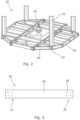
- the kit includes a plurality of groups of types of structural elements 22,30,40. That is, the structural elements include a plurality of subsets, with each subset being configured for a particular application within the structure 20. For example, two shorter subsets of the structural elements 30,40 are used to form the outer boundary of the internal platform support, with longer elements 22 being used to form the main skeleton of the structure. That is, the longer elements 22 form the centre portion of the internal platform support structure.
- the structural elements 22,30,40 within in each subset may be substantially the same to simplify assembly.
- Figure 3 shows a top view of a first structural element 30 used in the assembly shown in Figure 2 .
- the structural element 30 comprises a first end 32 and a second end 34 forming end regions at the two ends of its body 36.
- the first end 32 and second end 34 are each provided with apertures 38 configured to receive fasteners.
- both the first end 32 and second end 34 have four apertures 38, although it will be understood that the number of apertures 38 can vary depending on the location and the loading requirements of the structural element 30.
- the body 36 may be provided with one or more apertures 38.
- the structural elements 22,30,40 are configured to be connected together via the apertures 38,48 shown in Figures 3 to 5 .
- a first end 32 of a first structural element 30 is connected to a second end 34 of a second structural element 30.
- the apertures 38 of the first structural element 30 align with the apertures 38 of the second structural element 30.
- a fastener (not shown) can be inserted through the apertures 38 to connect the structural elements 30 together.
- a first end 32 of a first structural element 30 can align with a first end 32 of a second structural element 30, or to the apertures 38 disposed on the structural element body 36 of the structural element 30.
- the structural elements 22,30,40 comprise C-beams.
- Other types of beams may also be used, such as L-beams or square beams.
- the beams according to this example of this disclosure are cut from sheet metal and bent to form the C-beam shape.
- the sheet metal comprises steel, but other metals or metal alloys can be used, and the metal can be galvanised to provide rust resistance.
- the sheet metal can be cut to form the structural elements, for example by laser cutting using a computer numerical control (CNC) machine.
- CNC computer numerical control
- the apertures 38 may be drilled or cut into the structural element 30 with laser or a computer numerical control (CNC) machine.
- the thickness of the sheet metal can be between 0.5mm to 15mm. The thickness of the sheet metal may be chosen according to the structural requirements.
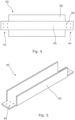
- Figures 4 to 6 show a further structural element 40 used in the assembly shown in Figure 2 .
- a blank for the structural element 40 is shown in Figure 4 .
- the structural element 40 comprises a first end 42 and a second end 44 at either ends of a structural element body 46.
- the first end 42 and second 44 are each provided with four apertures 48 configured to receive a fastener.
- the body 46 of the blank comprises two outwardly projecting sections 50 that are configured to be bent to form a C-beam when the structural element 40 is manufactured.
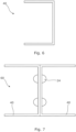
- the structural element body 46 is bent along the dashed lines shown in Figure 4 . Once bent, the structural element 40 forms a C-beam, as shown in Figure 5 and 6 .
- the first end 42 and second end 44 of the structural element 40 can also be bent relative to the longitudinal axis of the structural element body 46.
- first end 42 or second end 44 of one or both structural elements 40 can be bent to an angle such that, when connected their axes are angled relative to one another. It will be understood that the first end 42 and second end 44 of the structural element 40 can have different angles.
- the structural elements 22,30,40 can be cut and bent from sheet metal, these elements can be manufactured easily throughout the world and thereby minimising costs and maintaining consistency.
- the complexity of the supply chains can be minimised since only sheet metal is required as a precursor for creating the majority of the parts necessary for the assembly.
- the assembly of the internal platform support structure is not dependent on the manual steps of cutting and welding standard I-beams, which would otherwise be expensive and require more skilled labour.
- two structural elements 40 formed as C-beams can be connected together in pairs to form an I-beam, as shown in Figure 7 .
- a plate (not shown) may be put in between the two structural elements 40.
- the plate may be made of steel and be of any dimension; an example is for a 30 mm plate to be used.
- fasteners 24 For example, the two structural elements 40 can be connected together using rivets, as shown in Figure 7 .
- other types of fasteners for example bolts, can alternatively be used.
- lock-bolts are used where a collar is crimped or swaged onto the bolt or rivet.
- the structural elements 22,30,40 further comprise connector parts 60, as shown in Figure 8 .
- the connector part 60 comprises a first end 62 and a second end 64.
- the first and second ends 62,64 comprises apertures 66.
- the apertures 66 on the first end 62 or the second end 64 of the connector part 60 are configured to align with the apertures of a structural element such that the connector part 60 can be connected to a structural element 22,30,40 by fasteners 24.
- the connector part 60 therefore forms a bracket with reinforcing member 68 being provided between the first end 62 and the second end 64 to form a main body which reinforces the connector part 60.
- the connector part 60 can be used to connect perpendicular structural elements 22,30,40 together.
- the internal platform support structure 20 can be inserted into the top end of a monopile foundation and secured in place at fixing points, such that the one or more internal platforms are suspended within the monopile interior. In this way, the internal platform support structure 20 can provide a support for a platform onto which electronic components and electric wiring may be located.
- the assembly therefore provides a more cost-effective and simpler arrangement for forming an internal platform support structure, whilst also simplifying supply chains.
- the internal platform support structure 20 further comprises a flexible skirt (not shown) for attachment around a base of the internal platform support structure 20.
- the flexible skirt is configured to project away from the structure for separating an internal area above platform from an internal area of the wind turbine foundation structure below the platform.
- the skirt projects at roughly 45 degrees to facilitate its installation and fixing to the primary foundation structure.
- the skirt can be attached between the lowermost platform support and a plate that clamps the skirt to the internal platform support structure.
- the skirt As the internal platform support structure 20 is inserted into the interior of a wind turbine, the skirt unfolds and tightens around the internal wall of the wind turbine. Therefore, the skirt acts as a climate barrier to prevent the humid air trapped in the interior of the base of the foundation from corroding the materials housed on the wind turbine platform.
- the skirt is also easily replaceable by detaching it from its fixing.
- the skirt may be attached to its fixing by using a keder rail or any other suitable fixing arrangement.
- the internal platform support structure 20 may be provided for connection to a transition piece.
- the foundation structure may comprise an assembly of a monopile foundation in combination with a transition piece, with the support structure being connected to the transition piece.
- a monopile has been used as an example, other suitable foundation structures can be used as long as they provide sufficient space for a platform.
- the platform may sit in the turbine tower.
Landscapes
- Engineering & Computer Science (AREA)
- General Engineering & Computer Science (AREA)
- Mechanical Engineering (AREA)
- Structural Engineering (AREA)
- Chemical & Material Sciences (AREA)
- Civil Engineering (AREA)
- Life Sciences & Earth Sciences (AREA)
- Combustion & Propulsion (AREA)
- Sustainable Energy (AREA)
- Sustainable Development (AREA)
- Wind Motors (AREA)
- Architecture (AREA)
- Materials Engineering (AREA)
- Wood Science & Technology (AREA)
Priority Applications (6)
| Application Number | Priority Date | Filing Date | Title |
|---|---|---|---|
| EP23177354.0A EP4474579A1 (de) | 2023-06-05 | 2023-06-05 | Tragstruktur für eine interne plattform einer offshore-gründungsstruktur |
| AU2024283672A AU2024283672A1 (en) | 2023-06-05 | 2024-05-08 | Internal platform support structure for an offshore foundation structure |
| KR1020267000222A KR20260032535A (ko) | 2023-06-05 | 2024-05-08 | 해상 기초 구조물용 내부 플랫폼 지지 구조체 |
| PCT/EP2024/062690 WO2024251454A1 (en) | 2023-06-05 | 2024-05-08 | Internal platform support structure for an offshore foundation structure |
| US18/731,630 US20240401294A1 (en) | 2023-06-05 | 2024-06-03 | Internal platform support structure for an offshore foundation structure |
| TW113120525A TW202500836A (zh) | 2023-06-05 | 2024-06-03 | 用於離岸基礎結構之內部平台支撐結構 |
Applications Claiming Priority (1)
| Application Number | Priority Date | Filing Date | Title |
|---|---|---|---|
| EP23177354.0A EP4474579A1 (de) | 2023-06-05 | 2023-06-05 | Tragstruktur für eine interne plattform einer offshore-gründungsstruktur |
Publications (1)
| Publication Number | Publication Date |
|---|---|
| EP4474579A1 true EP4474579A1 (de) | 2024-12-11 |
Family
ID=86692971
Family Applications (1)
| Application Number | Title | Priority Date | Filing Date |
|---|---|---|---|
| EP23177354.0A Pending EP4474579A1 (de) | 2023-06-05 | 2023-06-05 | Tragstruktur für eine interne plattform einer offshore-gründungsstruktur |
Country Status (6)
| Country | Link |
|---|---|
| US (1) | US20240401294A1 (de) |
| EP (1) | EP4474579A1 (de) |
| KR (1) | KR20260032535A (de) |
| AU (1) | AU2024283672A1 (de) |
| TW (1) | TW202500836A (de) |
| WO (1) | WO2024251454A1 (de) |
Citations (5)
| Publication number | Priority date | Publication date | Assignee | Title |
|---|---|---|---|---|
| US20130174508A1 (en) * | 2012-01-06 | 2013-07-11 | General Electric Company | Platform assembly for a wind turbine tower |
| WO2014070084A2 (en) * | 2012-11-02 | 2014-05-08 | Sapa Ab | Platform and methods for assembling and mounting in wind tower |
| US20150361679A1 (en) * | 2014-06-17 | 2015-12-17 | Jereme Kent | Suspended Deck Systems, Kits, and Methods of Installing, Inspecting, and Repairing a Suspended Deck System |
| US20190040844A1 (en) * | 2017-08-04 | 2019-02-07 | GeoSea N.V. | Self-Supporting Support Structure for Wind Turbine Equipment |
| US20210277873A1 (en) * | 2020-03-09 | 2021-09-09 | Siemens Gamesa Renewable Energy A/S | Wind turbine |
Family Cites Families (2)
| Publication number | Priority date | Publication date | Assignee | Title |
|---|---|---|---|---|
| US2915819A (en) * | 1958-03-19 | 1959-12-08 | I D Pipe Cutter Company Inc | Pipe cutter |
| US3859877A (en) * | 1972-06-23 | 1975-01-14 | Dnd Corp | Inside pipe cutter apparatus |
-
2023
- 2023-06-05 EP EP23177354.0A patent/EP4474579A1/de active Pending
-
2024
- 2024-05-08 AU AU2024283672A patent/AU2024283672A1/en active Pending
- 2024-05-08 KR KR1020267000222A patent/KR20260032535A/ko active Pending
- 2024-05-08 WO PCT/EP2024/062690 patent/WO2024251454A1/en not_active Ceased
- 2024-06-03 TW TW113120525A patent/TW202500836A/zh unknown
- 2024-06-03 US US18/731,630 patent/US20240401294A1/en active Pending
Patent Citations (5)
| Publication number | Priority date | Publication date | Assignee | Title |
|---|---|---|---|---|
| US20130174508A1 (en) * | 2012-01-06 | 2013-07-11 | General Electric Company | Platform assembly for a wind turbine tower |
| WO2014070084A2 (en) * | 2012-11-02 | 2014-05-08 | Sapa Ab | Platform and methods for assembling and mounting in wind tower |
| US20150361679A1 (en) * | 2014-06-17 | 2015-12-17 | Jereme Kent | Suspended Deck Systems, Kits, and Methods of Installing, Inspecting, and Repairing a Suspended Deck System |
| US20190040844A1 (en) * | 2017-08-04 | 2019-02-07 | GeoSea N.V. | Self-Supporting Support Structure for Wind Turbine Equipment |
| US20210277873A1 (en) * | 2020-03-09 | 2021-09-09 | Siemens Gamesa Renewable Energy A/S | Wind turbine |
Also Published As
| Publication number | Publication date |
|---|---|
| TW202500836A (zh) | 2025-01-01 |
| AU2024283672A1 (en) | 2025-12-11 |
| WO2024251454A1 (en) | 2024-12-12 |
| US20240401294A1 (en) | 2024-12-05 |
| KR20260032535A (ko) | 2026-03-09 |
Similar Documents
| Publication | Publication Date | Title |
|---|---|---|
| EP2775141B1 (de) | Halteklammer für ausrüstungsteile für die innenseite eines turmes und windturbine | |
| EP3538760B1 (de) | Elektrische einheit für eine windturbine | |
| EP2136017B1 (de) | Windturbinenturmaufzug und Verfahren zur Montage eines Windturbinenturms | |
| JP5669930B2 (ja) | 風力発電装置用タワー及びその建設方法 | |
| EP2479430B1 (de) | Verfahren zur Montage von Schalensegmenten zum Formen von Turmabschnitten eines Hybrid-Windturbinenturms | |
| EP1933029A1 (de) | Verfahren zur befestigung von elementen in einem windgeneratorturm | |
| US20190368473A1 (en) | Standardized platform arrangement of a wind turbine | |
| EP3467304B1 (de) | Turmabschnitts zum automatischen anheben einer windturbine und verfahren zum automatischen anheben dafür | |
| EP2319648A1 (de) | Flanschverbindung für ein strukturelement | |
| EP2715015A2 (de) | Plattformkonstruktion und turm mit einer solchen integrierten plattform | |
| EP2253781A1 (de) | Verbundstoffverbindung für eine Windturbinenturmstruktur | |
| EP2534313B1 (de) | Gründung für windturbine | |
| CN108026899A (zh) | 用于风力发电机的塔 | |
| US20100132278A1 (en) | Method and system for coupling a stair platform to a tower of a wind energy turbine | |
| RU2741354C1 (ru) | Секция стальной башни ветроэнергетической установки для башни ветроэнергетической установки и способ ее изготовления | |
| US20240401294A1 (en) | Internal platform support structure for an offshore foundation structure | |
| WO2019038709A1 (en) | FRAME STRUCTURE FOR WIND TURBINE AND METHOD FOR MANUFACTURING FRAME STRUCTURE | |
| US12000376B2 (en) | Wind turbine tower section, wind turbine tower, and method for assembly | |
| EP4335806B1 (de) | Verbindungsstück zur verbindung von strukturmodulen von turmkränen | |
| EP3483431B1 (de) | Windturbinenarbeitsbühne | |
| EP2388411A1 (de) | Windturbinen-Turm | |
| WO2011147473A1 (en) | Jacket structure for offshore constructions | |
| JP3892764B2 (ja) | 法面受圧板 | |
| EP4004366A1 (de) | Tragstruktur für eine gondel einer windturbine | |
| JP5650309B1 (ja) | 太陽電池モジュールの設置架台 |
Legal Events
| Date | Code | Title | Description |
|---|---|---|---|
| PUAI | Public reference made under article 153(3) epc to a published international application that has entered the european phase |
Free format text: ORIGINAL CODE: 0009012 |
|
| STAA | Information on the status of an ep patent application or granted ep patent |
Free format text: STATUS: THE APPLICATION HAS BEEN PUBLISHED |
|
| AK | Designated contracting states |
Kind code of ref document: A1 Designated state(s): AL AT BE BG CH CY CZ DE DK EE ES FI FR GB GR HR HU IE IS IT LI LT LU LV MC ME MK MT NL NO PL PT RO RS SE SI SK SM TR |
|
| STAA | Information on the status of an ep patent application or granted ep patent |
Free format text: STATUS: REQUEST FOR EXAMINATION WAS MADE |
|
| 17P | Request for examination filed |
Effective date: 20250423 |
|
| GRAP | Despatch of communication of intention to grant a patent |
Free format text: ORIGINAL CODE: EPIDOSNIGR1 |
|
| STAA | Information on the status of an ep patent application or granted ep patent |
Free format text: STATUS: GRANT OF PATENT IS INTENDED |
|
| RIC1 | Information provided on ipc code assigned before grant |
Ipc: E02B 17/00 20060101AFI20260331BHEP Ipc: F03D 13/25 20160101ALI20260331BHEP Ipc: E04H 12/08 20060101ALN20260331BHEP |