EP4474174A2 - Reifen mit einer überwachungsvorrichtung - Google Patents
Reifen mit einer überwachungsvorrichtung Download PDFInfo
- Publication number
- EP4474174A2 EP4474174A2 EP24208472.1A EP24208472A EP4474174A2 EP 4474174 A2 EP4474174 A2 EP 4474174A2 EP 24208472 A EP24208472 A EP 24208472A EP 4474174 A2 EP4474174 A2 EP 4474174A2
- Authority
- EP
- European Patent Office
- Prior art keywords
- tyre
- accumulators
- equal
- electronic unit
- monitoring device
- Prior art date
- Legal status (The legal status is an assumption and is not a legal conclusion. Google has not performed a legal analysis and makes no representation as to the accuracy of the status listed.)
- Pending
Links
Images


Classifications
-
- B—PERFORMING OPERATIONS; TRANSPORTING
- B60—VEHICLES IN GENERAL
- B60C—VEHICLE TYRES; TYRE INFLATION; TYRE CHANGING; CONNECTING VALVES TO INFLATABLE ELASTIC BODIES IN GENERAL; DEVICES OR ARRANGEMENTS RELATED TO TYRES
- B60C23/00—Devices for measuring, signalling, controlling, or distributing tyre pressure or temperature, specially adapted for mounting on vehicles; Arrangement of tyre inflating devices on vehicles, e.g. of pumps or of tanks; Tyre cooling arrangements
- B60C23/02—Signalling devices actuated by tyre pressure
- B60C23/04—Signalling devices actuated by tyre pressure mounted on the wheel or tyre
- B60C23/0408—Signalling devices actuated by tyre pressure mounted on the wheel or tyre transmitting the signals by non-mechanical means from the wheel or tyre to a vehicle body mounted receiver
- B60C23/041—Means for supplying power to the signal- transmitting means on the wheel
-
- B—PERFORMING OPERATIONS; TRANSPORTING
- B60—VEHICLES IN GENERAL
- B60C—VEHICLE TYRES; TYRE INFLATION; TYRE CHANGING; CONNECTING VALVES TO INFLATABLE ELASTIC BODIES IN GENERAL; DEVICES OR ARRANGEMENTS RELATED TO TYRES
- B60C23/00—Devices for measuring, signalling, controlling, or distributing tyre pressure or temperature, specially adapted for mounting on vehicles; Arrangement of tyre inflating devices on vehicles, e.g. of pumps or of tanks; Tyre cooling arrangements
- B60C23/02—Signalling devices actuated by tyre pressure
- B60C23/04—Signalling devices actuated by tyre pressure mounted on the wheel or tyre
- B60C23/0491—Constructional details of means for attaching the control device
- B60C23/0493—Constructional details of means for attaching the control device for attachment on the tyre
Definitions
- the present invention relates to a tyre comprising a monitoring device, for example suitable for monitoring at least one physical quantity among temperature, pressure, deformation, acceleration.
- a tyre typically has a substantially toroidal structure around an axis of rotation of the same during operation, and it has an equatorial plane orthogonal to the axis of rotation, said equatorial plane being typically a plane of (substantial) geometric symmetry (e.g. ignoring any minor asymmetries, such as the tread design and/or the writing on the sides and/or structure or profile asymmetries).
- inner cavity it is meant the space delimited by the inner surface of tyre and by the surface of the rim facing towards the inner surface of the tyre, when mounted.
- row portion it is meant the portion of tyre placed between the two sides of the tyre, i.e. at the position of the tread band.
- radial and axial are used with reference respectively to a substantially perpendicular direction and to substantially parallel direction to the rotation axis of the tyre.
- tangential is used with reference to a direction generally faced according to the rolling direction of the tyre, substantially perpendicular to both the radial direction and the axial direction.
- footprint it is meant the portion of outer surface of the tread band which, during the rolling of the tyre mounted and subjected to a load (for example due to effect of the mounting under a vehicle), at each instant is in contact with the rolling surface.
- the footprint typically has a substantially null curvature (or substantially infinite curvature radius), or in each case it substantially assumes the conformation of the rolling surface.
- the desired physical quantity in particular the temperature, the deformation or the acceleration
- the temperature for example near to the rim or the temperature of the fluid present in the inner cavity can be very different from the temperature of the inner surface of the crown portion.
- the data measured is influenced by the temperature of the environment outside the wheel due to the heat conduction and/or the presence of external heat sources such as air flows from the radiators or the brake discs.
- the acceleration or of the deformation it is preferable a direct measurement of at least one of the radial, tangential and axial components of the acceleration or of the deformation undergone by an arbitrary point located onto the inner surface of the crown portion which is subjected to stress and deformation due to the cycle of entry and exit from the footprint, or more generally from the interaction between the tyre and the rolling surface.
- the detected acceleration or deformation signal information on the status and/or instantaneous behaviour of the tyre during use (e.g. size of the footprint, wear, hydroplaning, slippage, etc.).
- the acceleration and/or deformation sensor or the sensors, to a point close to where the greatest stresses are generated, i.e. near to the contact between the tyre and the rolling surface, as typically a point on the inner surface of the crown portion for example placed in correspondence with the central rib arranged in the axially central area of the tread, or in any case in a point on the inner surface of the crown portion corresponding to the most stressed area (both mechanically and thermally) of the tread during the tyre rolling.
- the rigid support comprises one or more layers of a base material, such as glass fibre, impregnated with a resin (e.g. epoxy).
- an electric energy accumulator/generator typically a battery (e.g. coin cell) comprising a metal capsule is used.
- This electric energy accumulator/generator typically has a significant weight.
- a non-rechargeable coin cell battery of the CR2032 type with an electric charge of about 200-250 mAh, can have a mass of about 3g.
- a used solution envisages to superimpose on each other, appropriately connected, an accumulator and the PCB with all the electronic components fixed on it, and to encapsulate the whole with an encapsulating material (e.g. polymeric resin), possibly inside a rigid containment body.
- an encapsulating material e.g. polymeric resin
- a housing can be provided (for example made of elastomeric material) to couple the device to the surface of the tyre by means of an attachment patch and/or one or more adhesives.
- the set of these structures entails a further increase in weight, for a total overall weight of the entire monitoring device which can reach 8-15g, almost all located in a small area, equal to the plan area of the container (for example, inscribed in a circle with diameter of 18-30mm).
- the Applicant in conducting tests at very high tyre rotation speeds (corresponding to extreme linear speeds of a corresponding vehicle, for example over 300km/h) with a monitoring device thus formed and fixed on the inner surface of the crown portion of the tyre in the axially central area, has verified that the location of the aforesaid overall mass, and in particular that of the accumulator, generates very intense stresses (in particular radial and tangential stresses).
- the radial acceleration is greater than in the areas outside the footprint. From experimental surveys, carried out by the Applicant at different speeds, the maximum acceleration at the entrance and exit of the footprint is about 1.5 times the radial acceleration outside the footprint. Moreover, in the footprint area, while the radial acceleration nullifies, a tangential acceleration appears which follows, along the footprint, a pattern similar to a sinusoid, whose amplitude has been experimentally determined by the Applicant to be equal to about the half of the radial acceleration at the footprint entry/exit.
- the acceleration with its rapid and intense variation on high-frequency cycles generates significant cyclic stresses, in radial direction (such as a 'hammering') and in tangential direction (shear), caused by the device on the tyre structures and/or vice-versa.
- these stresses have as direct consequence a significant and localized overheating of the monitoring device and/or of the tyre at the point of application of the monitoring device. Said overheating can significantly distort the reading of the correct operating temperature of the tyre by the monitoring device.
- said overheating and said mechanical stress and/or the combination of the two effects can lead to a damaging of the monitoring device (or its components, for example of the accumulator), relatively to its structural and/or functional integrity, and/or to its coupling with the inner surface of the tyre (for example decomposition and/or detachment of the adhesive for applying the device to the inner surface).
- said overheating and said mechanical stress and/or the combination of the two effects can lead to the loss of structural integrity of the crown portion of the tyre, even up to the formation of holes (so-called "blisters") at the tread band, caused by the localized decomposition of the tyre compound subsequently removed due to the rotational movement of the latter and/or to the delamination of the tread.
- blisters holes
- the Applicant has further realized that, when a non-rechargeable energy accumulator such as the aforementioned coin cell batteries is used, it is desirable for this accumulator to contain a sufficient amount of available energy for a period of several years, compatible with the whole life of the tyre.
- the Applicant has therefore faced the problem of making a monitoring device of at least one physical quantity (for example temperature, and/or pressure and/or acceleration and/or deformation) to be directly applied near to the inner surface of the crown portion of a tyre, being able to avoid or to limit the localized overheating and the consequent risk of detecting an incorrect temperature value and/or of loss of structural or functional integrity of the tyre and/or of the monitoring device, even at very high rotation speeds of the tyre, and also in presence of a significant accumulation of electric power, compatible with the average life of a tyre.
- at least one physical quantity for example temperature, and/or pressure and/or acceleration and/or deformation
- the aforesaid problem is solved with a monitoring device in which the electronic unit and the electric power supplier are fixed onto a flexible support, wherein the electric power supplier comprises a plurality of electric energy accumulators separately fixed onto the flexible support.
- the invention relates to a tyre comprising a monitoring device.
- the monitoring device is fixed on an inner surface of said tyre at a crown portion of said tyre.
- the monitoring device comprises an electronic unit and an electric power supplier electrically connected to said electronic unit.
- the electronic unit comprises: at least one sensor for detecting at least one of the following physical quantities: temperature, pressure, acceleration, deformation; a processing unit; a transceiver.
- the monitoring device further comprises a flexible support in a single body (for example a film made of thermoplastic material).
- the electronic unit is fixed onto said flexible support.
- said electric power supplier comprises a plurality of electric energy accumulators, each accumulator being electrically connected to said electronic unit and suitable for supplying said electronic unit.
- each of said accumulators is fixed onto said flexible support.
- 'electric power supplier it is meant a component structured to supply electric power to the electronic unit, which can consist in the abovesaid plurality of accumulators, wherein the power to be supplied is pre-accumulated (e.g. battery or capacitor), or it can contain a generator and/or receiver in situ of electric power suitable for re-charging the accumulators and, preferably, for directly supplying the electronic unit (for example a power recovery device or 'energy scavenging or harvesting' device, or an electromagnetic induction charger).
- a power recovery device or 'energy scavenging or harvesting' device for example a power recovery device or 'energy scavenging or harvesting' device, or an electromagnetic induction charger.
- the distribution of the electronic unit and of the accumulators onto the flexible support allows to avoid the addition of further material (for example encapsulating material) in the monitoring device, with a significant reduction of both the mass and the overall thermal inertia of the device itself, with advantages in the reliability, correctness and promptness of the detection of the physical quantities (in particular of the temperature), as well as in a lower attenuation of the radiofrequency signals transmitted and/or received by the monitoring device.
- further material for example encapsulating material
- the subdivision of the overall mass of the power supplier into several parts (the accumulators), each part having a non-negligible mass with respect to the overall mass of the device, allows to reduce the mass which assures, with the consequent aforesaid hammering phenomenon and of shear stress, on a respective single localized crown portion of the tyre: this entails a reduction of the consequent overheating of the crown portion and/or of the adhesive used to fix the monitoring device on the inner surface of the tyre and/or of the monitoring device itself.
- This, together with the fact that the electronic unit and each accumulator are at separate crown portions, allows a more correct detection of the value of the operating temperature of the tyre. All this in addition to the possibility of making available a high overall capacity for storing electric power in the monitoring device, given by the sum of the individual capacities of each accumulator, all to the benefit of the useful life of the monitoring device itself.
- the flexible support unlike a rigid support such as a PCB, also allows to the monitoring device to adapt to the deformation of the crown portion during rolling, in particular at the footprint. Moreover, it allows to distribute the stresses on a wider surface.
- each of said accumulators is an electric battery (for example a coin cell battery), more preferably non re-chargeable.
- each of said accumulators has circular plan.
- each of said accumulators comprises a rigid housing, for example made of metal.
- each of said accumulators has a charge capacity greater than or equal to 30 mAh, more preferably greater than or equal to 80 mAh, even more preferably greater than or equal to 100 mAh.
- each of said accumulators has a weight greater than or equal to about 0.5g, more preferably greater than or equal to about 1g.
- each of said accumulators has a weight lower than or equal to about 4 g.
- tyre suitable for heavy loads such as tyre for SUV, CUV, truck, bus, etc.
- batteries of greater weight can be used, till about 7-8 g.
- each of said accumulators is inscribed in a circle having diameter lower than or equal to 30 mm, more preferably lower than or equal to 25 mm, and/or circumscribed to a circle having diameter greater than or equal to 15 mm, more preferably greater than or equal to 17 mm.
- accumulators are able to supply sufficient energy for the operation of the device even over periods compatible with the average life of a tyre (depending on its different uses), and/or even in the presence of complex device functionalities, such as detection of different parameters such as acceleration, length and/or shape of the footprint, vertical load acting on the tyre, etc.
- each of said accumulators is structured to resist to temperatures greater than or equal to 100°C, more preferably greater than or equal to 110°C. In this way the accumulators resist to the overheating temperatures of the tyres.
- the monitoring device comprises an electric connection circuit for connecting each accumulator to said electronic unit, wherein preferably said electric connection circuit comprises at least two separate electric paths (one for the connection to the positive pole and one for the connection to the negative pole of the accumulators).
- said accumulators are electrically connected to said electronic unit in parallel. In this way the capacity of the accumulators is added, thus being able to obtain a significant duration of the monitoring device and/or an increase of the detection functionality.
- the electric connection circuit is fixed onto said flexible support, more preferably printed onto said flexible support with a conductive ink, even more preferably printed with serigraphic, lithographic, by ink jet, etc. technology.
- the electric connection circuit comprises copper conductive tracks, preferably obtained by chemical etching of a thin layer (e.g. few microns or few tens of microns) of copper. These technologies are particularly suitable for flexible substrates and are capable of creating conductive tracks resistant to flexion.
- a distance between each pair of accumulators is greater than or equal to 40 mm, more preferably greater than or equal to 50 mm.
- 'distance it is meant the length of the shortest line on the inner surface of the tyre (in the undeformed state) joining the edges of the two considered accumulators (e.g. the edges of a housing of an accumulator).
- the Applicant has observed that in this case the temperature distributions (determined by the heating phenomenon due to the cyclical stresses of entry/exit from the footprint and the phenomenon of the propagation of the produced heat) individually associated with each accumulator are spatially substantially decoupled from each other, so that a localized heat build-up is avoided.
- the accumulators are sufficiently far apart from each other to prevent that the local heating of the individual accumulators adds up in a point, with the further advantages described above.
- each pair of accumulators (14) is lower than or equal to 250 mm, more preferably lower than or equal to 200 mm, even more preferably lower than or equal to 150 mm.
- said length of the electric connection circuit and/or the extension of the overall device is limited, and the consequent complications in terms of fabrication, coupling (bonding) with the tyre, structural resistance of the tracks, etc are reduced.
- the equatorial plane of the tyre crosses said monitoring device, more preferably it crosses said electronic unit, for example at said sensor.
- the device preferably the sensor
- the device is applied in a portion of the tyre subjected to the greatest stresses and - therefore - of greater interest in the case of signal measurements (e.g. accelerometers) from which information on the status and/or on the instantaneous behaviour of the tyre during the use is to be detected.
- said at least one sensor is suitable for detecting at least two of the following physical quantities: temperature, pressure, acceleration, deformation, for example temperature and pressure. Even more preferably said at least one sensor is suitable for detecting at least three of, or all four, the abovesaid physical quantities. Preferably said at least one sensor is suitable for detecting at least said acceleration and/or said deformation, more preferably at least a radial component and/or a tangential component of said acceleration and/or of said deformation. In this way the monitoring device provides particularly useful data for obtaining the status and/or the operation of the tyre, and/or the behaviour of the vehicle on which it is mounted.
- said flexible support is fixed to the inner surface of said tyre, more preferably by means of a layer of adhesive (e.g. a pressure sensitive adhesive).
- a layer of adhesive e.g. a pressure sensitive adhesive
- said flexible support is substantially inextensible. In this way the shear stresses are distributed and/or the stresses on the tracks of the connection circuit are limited.
- flexible support it is generally meant a support made of a material (including a composite/layers material) which, if used for making a square-shaped slab on the side significantly greater than the circumferential extension of the area of entry or exit from the footprint region of a tyre (for example a 120 mm x 120 mm surface plate) and of a thickness equal to the support, allows this plate to conform - to ambient temperature - to a cylindrical surface of radius smaller than the normal curvature radius of a tyre inflated to its nominal pressure (for example a cylindrical surface of radius 200 mm, preferably 100 mm, more preferably 50) without breaking or undergoing a permanent deformation.
- a material including a composite/layers material
- non extensible support it is generally meant a support with a thickness from about 10 ⁇ m to about 400 ⁇ m, preferably from about 50 ⁇ m to about 200 ⁇ m, made of a material (including a composite/layers material) having traction elastic modulus preferably greater than 0.1 GPa, more preferably greater than 0.5 GPa at 23°C.
- said flexible support (13) is a film of an elastomeric or thermoplastic material selected from the following group: nylon, PET, PEN, polyimide, EPDM, diene polymers and polyurethane resins. Paper substrates, thin sheets in epoxy resin (possibly reinforced, for example with glass fibres) or super-thin and therefore flexible sheets of silicon (or another semiconductor) can also be used.
- one or more of said at least one sensor, said processing unit and said transceiver is a pre-fabricated electronic component.
- This pre-fabricated electronic component can be (directly) fixed, and electronically connected, to the electric connection circuit, for example by bonding with conductive adhesives and/or welding.
- one or more of said at least one sensor, said processing unit and said transceiver is directly made in situ onto the flexible support (i.e. it is not pre-fabricated), for example by printing or deposition technologies.
- At least two among said sensor, said processing unit and said transceiver are arranged in a single assembly, preferably pre-fabricated (for example by means of a containment body which houses at least partially said at least two among said sensor, said processing unit and said transceiver).
- a containment body which houses at least partially said at least two among said sensor, said processing unit and said transceiver.
- said electronic unit has an overall weight greater than or equal to about 1g, and/or lower than or equal to about 8g, more preferably lower than or equal to about 6g.
- all weight of a given element it is meant its total weight, for example considering all the active and passive components, the possible container, etc.
- said plurality of accumulators comprises a first and a second accumulator arranged at opposite sides of said electronic unit. By interposing the electronic unit between the two accumulators, the latter are placed at a greater mutual distance than a placement on the same side of the electronic unit, keeping the same overall encumbrance in a plan view of the monitoring device.
- said plurality of accumulators comprises two and no more than two accumulators. In this way it is limited the plan encumbrance and the complexity of the monitoring device.
- said monitoring device has a plan with elongated shape along a longitudinal direction of main development, wherein said first and second accumulators are arranged at longitudinally opposite ends of the monitoring device.
- This shape has proved to be rational and particularly efficient for limiting the overheating and/or for guaranteeing the integrity of the monitoring device.
- the accumulators i.e. the typically heavier parts
- the stress radial and/or tangential stresses
- the relative deformations produced by the accumulators on the flexible support in the area of the circuits and of the electronic unit located substantially in the central area of the support
- the monitoring device is fixed to the inner surface of the tyre so that a straight line passing through the centres of mass of the accumulators (e.g. a straight line coinciding with the main development longitudinal direction) forms with a direction of intersection of the equatorial plane with the inner surface of the tyre (or an its parallel direction) a right angle or an acute angle greater than or equal to 20°, more preferably greater than or equal to 25°.
- a straight line passing through the centres of mass of the accumulators e.g. a straight line coinciding with the main development longitudinal direction
- a right angle or an acute angle greater than or equal to 20°, more preferably greater than or equal to 25°.
- said acute angle is lower than or equal to 70°, more preferably lower than or equal to 65°.
- This positioning of the monitoring device, with elongated shape, neither parallel nor perpendicular to the equatorial plane, but oblique, allows to arrange the masses of the accumulators in such a way that they do not all lie on the same circumferential tread portion (as would instead happen in the case of positioning parallel to the equatorial plane).
- an aspect ratio between a longitudinal length of the monitoring device and a width along a direction perpendicular to the longitudinal direction is greater than or equal to 2, more preferably greater than or equal to 2.5, even more preferably greater than or equal to 3, and/or lower than or equal to 6, more preferably lower than or equal to 5.
- These values of the aspect ratio give to the monitoring device a main development length with respect to which the device itself can be fixed to the tyre with an optimal orientation with respect to the stresses, while the dimension perpendicular to it, due to its much smaller length, undergoes a much lower degree of stresses.
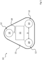
- said plurality of accumulators comprises at least a third accumulator, more preferably even at least a fourth accumulator (and preferably no more than four accumulators). In this way the capacity (and/or the supplied voltage) of the power supplier is enhanced.
- said accumulators are arranged around said electronic unit, more preferably substantially angularly equidistant from each other, even more preferably along a circle which surrounds said electronic unit, even more preferably centred onto (a geometric centre of) said electronic unit. In this way the distance between the accumulators, for a given plan encumbrance, is maximized.
- said accumulators are arranged at end positions of said flexible support (e.g. close to an edge of said flexible support). As explained above, in this way the stresses and the deformations exerted by the accumulators on the electronic components and on the conductive tracks of the device are reduced.
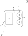
- a tyre in partial perspective section
- a monitoring device 10 according to the present invention.
- the same reference number is used for the same elements, also in their embodiments.
- the monitoring device 10 comprises an electronic unit 11 and an electric power supplier 12 electrically connected to the electronic unit.
- the monitoring device 10 further comprises a flexible support 13 in a single body, fixed onto the inner surface 15 of the tyre at a crown portion 16 of the tyre 1 (i.e. the portion of tyre at the tread band 17).
- the electronic unit and the electric power supplier are fixed onto the flexible support 13, for example by means of conductive adhesive (e.g. Henkel ® 3104 WXL) and of structural adhesive (e.g. Henkel ® LOCTITE ® 312TM).
- the electric power supplier 12 comprises a plurality of distinct electrical energy accumulators 14, each accumulator 14 being electrically connected to the electronic unit for supplying the electronic unit. Each accumulator 14 is directly fixed onto the flexible support 13.
- each accumulator 14 is an electric battery, for example a coin cell battery of the type CR2032HR sold by Maxell ® (capacity 200 mAh, weight 3g, diameter and thickness 20x3.2mm), or BR1632A sold by Panasonic ® (capacity 120mAh, 1.5g, 6x3.2mm).
- the typical voltage is equal to 3V, and the operating temperature range from -40°C to +125°C (or possibly in sub-intervals, depending on the type of envisaged use).
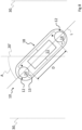
- the monitoring device 10 comprises an electric connection circuit 18 (shown only schematically in the figures) for connecting each accumulator 14 to the electronic unit 11, preferably in parallel (as exemplarily shown in a schematic way only in figure 4 ).
- the tracks of the electric connection circuit are made with a conductive ink (e.g. silver conductive ink DuPont ® 5025) printed with serigraphic technique directly on the flexible substrate.
- the electronic unit 11 comprises (not shown) at least one sensor for detecting at least one of the following physical quantities: temperature, pressure, acceleration; a processing unit and a transceiver.
- the electronic unit can include a pre-fabricated assembly model FXTH87091 1DT1 sold by NXP Semiconductors ® , comprising a processing unit and a plurality of sensors suitable for detecting all the three physical quantities: temperature, pressure and acceleration.
- This assembly also includes an RF transceiver with a transceiver frequency of 315-434 MHz. In an exemplary embodiment, it can be used a further transceiver fixed onto the flexible support separately from the aforementioned assembly, usable on a different frequency band (for example with Wifi or Bluetooth ® technology).
- the flexible support 13 is a film made of polyimide (e.g. Kapton ® by DuPont ® ).
- a layer of adhesive (not shown), for example pressure sensitive, may be arranged to bond the lower face of the flexible support to the inner surface of the tyre.
- the device 10 is applied to the inner surface of the tyre in such a way that the equatorial plane 20 of the tyre crosses the monitoring device 10, and more specifically it crosses the electronic unit 11 (so that the sensor is located at or near to the central rib 21 of the tread 17).
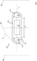
- the plurality of accumulators 14 comprises two and no more than two accumulators, as shown exemplarily in Figures 2 , 3 and 4 .
- the two accumulators are arranged on opposite parts of the electronic unit 11, as exemplarily shown in the figures 3 and 4 .
- the monitoring device 10 has a plan (e.g. defined by the plan of the flexible support 13) with an elongated shape along a longitudinal direction L of main development, the two accumulators being arranged at longitudinally opposite ends of the monitoring device.
- the dimensions L1xL2 respectively along this longitudinal direction L and along the dimension perpendicular to it (in the plane of figure 3 ) are equal to about 80x55mm (aspect ratio R equal to about 1.5) and the distance D between the two accumulators is equal to about 45 mm.
- the dimensions L1xL2 are equal to about 110x30mm (aspect ratio R equal to 3.7) or about 80x25mm (R equal to 3.2).
- the distance D between the two accumulators is equal to about 69 mm in the case of the dimensions 110x30mm, while for dimensions equal to 80X25mm the distance D is equal to about 50 mm.
- an angle A formed between a straight line L passing through the centres of mass of the accumulators 14 (in the example coinciding with the direction L of main development) and the direction of intersection 20' between the equatorial plane and the inner surface is exemplarily a right angle.
- the electronic unit 11 can lie on the equatorial plane, while the accumulators 14 lie completely outside the equatorial plane, and thus far from the central rib.
- the acute angle A formed between the straight-line L and the intersection 20' between the equatorial plane and the inner surface is exemplarily equal to 45°.
- the electronic unit 11 can lie on the equatorial plane, while the accumulators 14 lie far enough from the central rib, and at the same time the effects on the flexible support of possible deformations of the tyre and/or of the flexible support along the axial direction are reduced.
- the plurality of accumulators comprises three and, respectively, four accumulators 14 arranged in an angularly equidistant way along a circle circumscribed to the electronic unit 11 and centred on the electronic unit, in positions placed towards the edges of the flexible support 13.
Landscapes
- Engineering & Computer Science (AREA)
- Mechanical Engineering (AREA)
- Tires In General (AREA)
- Measuring Fluid Pressure (AREA)
- Arrangements For Transmission Of Measured Signals (AREA)
Applications Claiming Priority (5)
| Application Number | Priority Date | Filing Date | Title |
|---|---|---|---|
| IT201800007769 | 2018-08-02 | ||
| IT201800010794 | 2018-12-04 | ||
| IT201800010795 | 2018-12-04 | ||
| PCT/IT2019/050174 WO2020026282A1 (en) | 2018-08-02 | 2019-07-25 | Tyre comprising a monitoring device |
| EP19755975.0A EP3829901B1 (de) | 2018-08-02 | 2019-07-25 | Reifen mit überwachungsvorrichtung |
Related Parent Applications (2)
| Application Number | Title | Priority Date | Filing Date |
|---|---|---|---|
| EP19755975.0A Division EP3829901B1 (de) | 2018-08-02 | 2019-07-25 | Reifen mit überwachungsvorrichtung |
| EP19755975.0A Division-Into EP3829901B1 (de) | 2018-08-02 | 2019-07-25 | Reifen mit überwachungsvorrichtung |
Publications (2)
| Publication Number | Publication Date |
|---|---|
| EP4474174A2 true EP4474174A2 (de) | 2024-12-11 |
| EP4474174A3 EP4474174A3 (de) | 2025-03-05 |
Family
ID=67667890
Family Applications (6)
| Application Number | Title | Priority Date | Filing Date |
|---|---|---|---|
| EP24208477.0A Pending EP4491419A3 (de) | 2018-08-02 | 2019-07-25 | Reifen mit einer überwachungsvorrichtung |
| EP25153970.6A Pending EP4520553A3 (de) | 2018-08-02 | 2019-07-25 | Reifen mit einer überwachungsvorrichtung |
| EP19755974.3A Active EP3829900B1 (de) | 2018-08-02 | 2019-07-25 | Reifen mit überwachungsvorrichtung |
| EP19755975.0A Active EP3829901B1 (de) | 2018-08-02 | 2019-07-25 | Reifen mit überwachungsvorrichtung |
| EP24208472.1A Pending EP4474174A3 (de) | 2018-08-02 | 2019-07-25 | Reifen mit einer überwachungsvorrichtung |
| EP19755976.8A Active EP3829902B1 (de) | 2018-08-02 | 2019-07-25 | Reifen mit ueberwachungsvorrichtung |
Family Applications Before (4)
| Application Number | Title | Priority Date | Filing Date |
|---|---|---|---|
| EP24208477.0A Pending EP4491419A3 (de) | 2018-08-02 | 2019-07-25 | Reifen mit einer überwachungsvorrichtung |
| EP25153970.6A Pending EP4520553A3 (de) | 2018-08-02 | 2019-07-25 | Reifen mit einer überwachungsvorrichtung |
| EP19755974.3A Active EP3829900B1 (de) | 2018-08-02 | 2019-07-25 | Reifen mit überwachungsvorrichtung |
| EP19755975.0A Active EP3829901B1 (de) | 2018-08-02 | 2019-07-25 | Reifen mit überwachungsvorrichtung |
Family Applications After (1)
| Application Number | Title | Priority Date | Filing Date |
|---|---|---|---|
| EP19755976.8A Active EP3829902B1 (de) | 2018-08-02 | 2019-07-25 | Reifen mit ueberwachungsvorrichtung |
Country Status (5)
| Country | Link |
|---|---|
| US (3) | US11981164B2 (de) |
| EP (6) | EP4491419A3 (de) |
| CN (3) | CN112566798A (de) |
| RU (1) | RU2762050C1 (de) |
| WO (3) | WO2020026282A1 (de) |
Families Citing this family (10)
| Publication number | Priority date | Publication date | Assignee | Title |
|---|---|---|---|---|
| RU2762050C1 (ru) * | 2018-08-02 | 2021-12-15 | Пирелли Тайр С.П.А. | Шина, содержащая устройство мониторинга |
| US11260705B2 (en) | 2019-12-17 | 2022-03-01 | The Goodyear Tire & Rubber Company | Flexible tire sensor unit |
| WO2021124366A1 (en) * | 2019-12-19 | 2021-06-24 | Pirelli Tyre S.P.A. | Tyre for motor-cycles comprising a monitoring device |
| CN112339511B (zh) * | 2020-11-27 | 2024-07-16 | 智周博行(北京)科技有限公司 | 轮胎检测装置、轮胎及车辆 |
| JP7666521B2 (ja) * | 2020-12-07 | 2025-04-22 | 住友ゴム工業株式会社 | タイヤ |
| US11845347B2 (en) | 2021-05-12 | 2023-12-19 | David Alan Copeland | Precision charging control of an untethered vehicle with a modular vehicle charging roadway |
| DE102021117410B4 (de) * | 2021-07-06 | 2025-11-13 | Saf-Holland Gmbh | Reifenbefüllungssystem und Nutzfahrzeug mit einem Reifenbefüllungssystem sowie Verfahren zum Betreiben eines Reifenbefüllungssystems |
| IT202200003239A1 (it) | 2022-02-22 | 2023-08-22 | Pirelli | Metodo e sistema di controllo di un veicolo in presenza di acquaplano |
| WO2023228224A1 (en) * | 2022-05-27 | 2023-11-30 | Pirelli Tyre S.P.A. | Tyre comprising a monitoring device |
| IT202300025719A1 (it) | 2023-12-01 | 2025-06-01 | Pirelli | Metodo e sistema di rilevamento di una condizione di acquaplano di uno pneumatico su una superficie |
Citations (19)
| Publication number | Priority date | Publication date | Assignee | Title |
|---|---|---|---|---|
| US4862486A (en) | 1987-11-16 | 1989-08-29 | Wing J Keith | Revolution counter attached to tires |
| US5749984A (en) | 1995-12-29 | 1998-05-12 | Michelin Recherche Et Technique S.A. | Tire monitoring system and method |
| US5960844A (en) | 1997-12-22 | 1999-10-05 | Bridgestone/Firestone, Inc. | Method and apparatus for monitoring conditions of a vehicle tire |
| US5977870A (en) | 1997-12-22 | 1999-11-02 | Bridgestone/Firestone, Inc. | Method and apparatus for transmitting stored data and engineering conditions of a tire to a remote location |
| US20070013503A1 (en) | 2005-07-14 | 2007-01-18 | Kuender Co., Ltd. | Patch-type tire status monitoring apparatus |
| DE102005051136A1 (de) | 2005-10-26 | 2007-05-03 | Leopold Kostal Gmbh & Co. Kg | Reifendruck-Sensormodul für einen Kraftfahrzeugreifen |
| WO2007048621A1 (en) | 2005-10-28 | 2007-05-03 | Pirelli Tyre S.P.A. | A tyre comprising an electronic unit and a method of installing said electronic unit into said tyre |
| WO2007121768A1 (en) | 2006-04-26 | 2007-11-01 | Pirelli Tyre S.P.A. | A tyre comprising an electronic unit and a method of installing said electronic unit into said tyre |
| DE102007014097A1 (de) | 2007-03-21 | 2008-09-25 | Continental Teves Ag & Co. Ohg | Reifenmodul |
| US20080303634A1 (en) | 2007-06-08 | 2008-12-11 | Bridgestone Corporation | Tire revolution detecting system |
| US20090134710A1 (en) | 2005-06-10 | 2009-05-28 | Michelin Recherche Et Technique S.A. | Inductive coupling of pulses from piezoelectric device |
| US20100007477A1 (en) | 1999-04-29 | 2010-01-14 | Wilson Paul B | Tire with monitoring device |
| US20100097662A1 (en) | 2008-10-20 | 2010-04-22 | John Eric Churilla | System and method for scanning and processing printed media |
| WO2013098712A1 (en) | 2011-12-29 | 2013-07-04 | Pirelli Tyre S.P.A. | Monitoring device for tyres for vehicle wheels, tyre for vehicle wheels provided with said monitoring device, and method for installing an electronic unit in said tyre |
| WO2013098711A1 (en) | 2011-12-29 | 2013-07-04 | Pirelli Tyre S.P.A. | Monitoring device for tyres for vehicle wheels, tyre for vehicle wheels provided with said monitoring device, and method for installing an electronic unit in said tyre |
| DE102012007071A1 (de) | 2012-04-11 | 2013-10-17 | Huf Hülsbeck & Fürst Gmbh & Co. Kg | Reifenmodul und damit ausgestatteter Reifen |
| US20140118134A1 (en) | 2012-10-26 | 2014-05-01 | Samsung Electronics Co., Ltd. | Tire pressure monitoring system |
| WO2016042580A1 (en) | 2014-09-17 | 2016-03-24 | Ste S.R.L. | Transmitting device and method for wireless transmission of measured parameters |
| WO2018065846A1 (en) | 2016-10-04 | 2018-04-12 | Pirelli Tyre S.P.A. | Device for securing an electronic unit to a tyre and a tyre comprising an electronic unit |
Family Cites Families (46)
| Publication number | Priority date | Publication date | Assignee | Title |
|---|---|---|---|---|
| US5731754A (en) * | 1994-06-03 | 1998-03-24 | Computer Methods Corporation | Transponder and sensor apparatus for sensing and transmitting vehicle tire parameter data |
| US7549327B2 (en) * | 2001-02-16 | 2009-06-23 | Automotive Technologies International, Inc. | Tire-mounted energy generator and monitor |
| DE19532914A1 (de) * | 1995-09-06 | 1997-03-13 | Dynatron Ag | Vorrichtung zur Überwachung des Luftdruckes von luftbereiften Fahrzeugrädern |
| US7429801B2 (en) * | 2002-05-10 | 2008-09-30 | Michelin Richerche Et Technique S.A. | System and method for generating electric power from a rotating tire's mechanical energy |
| US6994133B2 (en) | 2002-10-01 | 2006-02-07 | Michelin Recherche Et Technique S.A. | Low or no pressure usage indicator for a tire |
| ES2292984T3 (es) * | 2003-06-12 | 2008-03-16 | Pirelli Tyre S.P.A. | Neumatico equipado con un dispositivo de monitorizacion, y procedimiento para instalar el dispositivo sobre la superficie interior del neumatico. |
| JP4052290B2 (ja) | 2003-08-29 | 2008-02-27 | オムロン株式会社 | 無線icタグ接合方法、無線icタグ付き物品、及び車両 |
| US20050076982A1 (en) | 2003-10-09 | 2005-04-14 | Metcalf Arthur Richard | Post patch assembly for mounting devices in a tire interior |
| FR2870397A1 (fr) | 2004-05-13 | 2005-11-18 | Michelin Soc Tech | Cablage pour article en caoutchouc avec electronique integree et procede pour instrumenter un tel article |
| JP4713863B2 (ja) | 2004-08-27 | 2011-06-29 | 住友電気工業株式会社 | タイヤセンサユニット、タイヤ状態検出装置及びタイヤ |
| FR2878782B1 (fr) | 2004-12-02 | 2007-01-12 | Michelin Soc Tech | Element de la liaison au sol d'un vehicule, pneumatique et liaison au sol d'un vehicule |
| JP4847022B2 (ja) | 2005-01-28 | 2011-12-28 | 京セラ株式会社 | 発声内容認識装置 |
| DE102005016354A1 (de) | 2005-04-09 | 2006-10-12 | Continental Aktiengesellschaft | Fahrzeugreifen |
| EP1896276B1 (de) | 2005-06-28 | 2013-02-20 | PIRELLI TYRE S.p.A. | Mit einer vorrichtung zur erfassung mindestens eines funktionalen parameters des reifens selbst versehener reifen und verfahren zur erfassung mindestens eines funktionalen parameters in einem reifen |
| FR2894519B1 (fr) * | 2005-12-13 | 2010-02-12 | Michelin Soc Tech | Emplatre pour fixer un systeme electronique sur un pneumatique |
| FR2899150B1 (fr) | 2006-04-04 | 2010-09-10 | Michelin Soc Tech | Dispositif de fixation d'un module sur la paroi interne d'un pneumatique |
| WO2008012850A1 (en) | 2006-07-28 | 2008-01-31 | Pirelli Tyre S.P.A. | Wheel for vehicles |
| JP4705560B2 (ja) | 2006-12-05 | 2011-06-22 | 住友ゴム工業株式会社 | Icタグ、それを取付けた空気入りタイヤ、およびicタグの取付方法 |
| DE102008007774A1 (de) * | 2008-02-06 | 2009-08-13 | Robert Bosch Gmbh | Biegewandler zum Erzeugen von elektrischer Energie aus mechanischen Verformungen |
| US20100271191A1 (en) | 2008-10-07 | 2010-10-28 | De Graff Bassel | Systems, devices, and methods utilizing stretchable electronics to measure tire or road surface conditions |
| FR2940930B1 (fr) | 2009-01-09 | 2011-11-18 | Michelin Soc Tech | Ensemble de fixation d'un module electronique a une paroi interne d'un pneumatique |
| BRPI1009748A2 (pt) | 2009-02-27 | 2019-04-09 | Givent Ltd | elemento de construção, e um método a produção de elemento |
| JP5546808B2 (ja) * | 2009-07-03 | 2014-07-09 | 日立マクセル株式会社 | 扁平形電池の取付方法及び回転部分に取り付けられる装置 |
| CN101691103A (zh) * | 2009-10-16 | 2010-04-07 | 广东省粤晶高科股份有限公司 | 系统级封装的汽车轮胎压力传感器轮胎模块核心组件 |
| WO2011051800A1 (en) * | 2009-10-30 | 2011-05-05 | Pirelli Tyre S.P.A. | Method for generating electric energy in a tyre |
| CN201532645U (zh) * | 2009-11-09 | 2010-07-21 | 青岛高校软控股份有限公司 | 补片式rfid轮胎电子标签装置 |
| US9429497B2 (en) * | 2011-12-29 | 2016-08-30 | Michelin Recherche Et Technique S.A. | System and method for determining tire uniformity parameters from piezoelectric measurements in the tire counter-deflection zone |
| JP5346099B2 (ja) | 2012-02-22 | 2013-11-20 | シリコン・バレイ・マイクロ・シイ・コーポレーション | 感度が向上したタイヤ圧力センサ・システムと節電 |
| CN203254901U (zh) * | 2013-01-31 | 2013-10-30 | 上海保隆汽车科技股份有限公司 | 轮胎压力监测传感器 |
| US20150097662A1 (en) | 2013-10-08 | 2015-04-09 | Cub Elecparts Inc. | Flexible board type tire pressure sensor device |
| BR112016022147A2 (pt) | 2014-03-28 | 2017-08-15 | Pirelli | Dispositivo de sensor de pneu, e, pneu de veículo |
| DE102014205923B4 (de) | 2014-03-31 | 2023-06-07 | Aktiebolaget Skf | Modul zum Erfassen einer physikalischen Größe eines gasförmigen Mediums |
| WO2015194930A1 (en) | 2014-06-19 | 2015-12-23 | Salutica Allied Solutions Sdn. Bhd. | Wireless tire monitoring system |
| US20160317068A1 (en) | 2015-04-30 | 2016-11-03 | Verily Life Sciences Llc | Electronic devices with encapsulating silicone based adhesive |
| US9935563B2 (en) * | 2015-08-05 | 2018-04-03 | Nxp Usa, Inc. | Electrical energy generation within a vehicle tire |
| US10406866B2 (en) * | 2016-02-26 | 2019-09-10 | The Goodyear Tire & Rubber Company | Tire sensor for a tire monitoring system |
| DE102016222535A1 (de) * | 2016-11-16 | 2018-05-17 | Continental Reifen Deutschland Gmbh | Fahrzeugreifen |
| DE102017104732A1 (de) * | 2017-03-07 | 2018-09-13 | Infineon Technologies Ag | Reifensensorvorrichtung und Verfahren |
| EP3501855B1 (de) * | 2017-12-20 | 2022-04-27 | The Goodyear Tire & Rubber Company | Sensorsystem zur überwachung des reifenverschleisses |
| RU2762050C1 (ru) * | 2018-08-02 | 2021-12-15 | Пирелли Тайр С.П.А. | Шина, содержащая устройство мониторинга |
| US10960714B2 (en) * | 2018-09-26 | 2021-03-30 | The Goodyear Tire & Rubber Company | Tire with printed shear sensors |
| US11385083B2 (en) * | 2018-12-07 | 2022-07-12 | Mohammad Kabany | Method for measuring and/or processing measured pressure and/or humidity values |
| IT201800020335A1 (it) * | 2018-12-20 | 2020-06-20 | Pirelli | Pneumatico comprendente un dispositivo di rilevamento |
| MX2021011448A (es) * | 2019-03-20 | 2021-10-13 | Cipher Skin | Sensor para monitoreo de estructuras fisicas. |
| US11260705B2 (en) * | 2019-12-17 | 2022-03-01 | The Goodyear Tire & Rubber Company | Flexible tire sensor unit |
| WO2021124366A1 (en) * | 2019-12-19 | 2021-06-24 | Pirelli Tyre S.P.A. | Tyre for motor-cycles comprising a monitoring device |
-
2019
- 2019-07-25 RU RU2021103559A patent/RU2762050C1/ru active
- 2019-07-25 EP EP24208477.0A patent/EP4491419A3/de active Pending
- 2019-07-25 EP EP25153970.6A patent/EP4520553A3/de active Pending
- 2019-07-25 EP EP19755974.3A patent/EP3829900B1/de active Active
- 2019-07-25 US US17/261,438 patent/US11981164B2/en active Active
- 2019-07-25 US US17/261,372 patent/US12151518B2/en active Active
- 2019-07-25 WO PCT/IT2019/050174 patent/WO2020026282A1/en not_active Ceased
- 2019-07-25 EP EP19755975.0A patent/EP3829901B1/de active Active
- 2019-07-25 CN CN201980051418.6A patent/CN112566798A/zh active Pending
- 2019-07-25 EP EP24208472.1A patent/EP4474174A3/de active Pending
- 2019-07-25 WO PCT/IT2019/050175 patent/WO2020026283A1/en not_active Ceased
- 2019-07-25 US US17/261,402 patent/US11780276B2/en active Active
- 2019-07-25 EP EP19755976.8A patent/EP3829902B1/de active Active
- 2019-07-25 CN CN201980051436.4A patent/CN112566799A/zh active Pending
- 2019-07-25 WO PCT/IT2019/050173 patent/WO2020026281A1/en not_active Ceased
- 2019-07-25 CN CN201980051424.1A patent/CN112533777B/zh active Active
Patent Citations (19)
| Publication number | Priority date | Publication date | Assignee | Title |
|---|---|---|---|---|
| US4862486A (en) | 1987-11-16 | 1989-08-29 | Wing J Keith | Revolution counter attached to tires |
| US5749984A (en) | 1995-12-29 | 1998-05-12 | Michelin Recherche Et Technique S.A. | Tire monitoring system and method |
| US5960844A (en) | 1997-12-22 | 1999-10-05 | Bridgestone/Firestone, Inc. | Method and apparatus for monitoring conditions of a vehicle tire |
| US5977870A (en) | 1997-12-22 | 1999-11-02 | Bridgestone/Firestone, Inc. | Method and apparatus for transmitting stored data and engineering conditions of a tire to a remote location |
| US20100007477A1 (en) | 1999-04-29 | 2010-01-14 | Wilson Paul B | Tire with monitoring device |
| US20090134710A1 (en) | 2005-06-10 | 2009-05-28 | Michelin Recherche Et Technique S.A. | Inductive coupling of pulses from piezoelectric device |
| US20070013503A1 (en) | 2005-07-14 | 2007-01-18 | Kuender Co., Ltd. | Patch-type tire status monitoring apparatus |
| DE102005051136A1 (de) | 2005-10-26 | 2007-05-03 | Leopold Kostal Gmbh & Co. Kg | Reifendruck-Sensormodul für einen Kraftfahrzeugreifen |
| WO2007048621A1 (en) | 2005-10-28 | 2007-05-03 | Pirelli Tyre S.P.A. | A tyre comprising an electronic unit and a method of installing said electronic unit into said tyre |
| WO2007121768A1 (en) | 2006-04-26 | 2007-11-01 | Pirelli Tyre S.P.A. | A tyre comprising an electronic unit and a method of installing said electronic unit into said tyre |
| DE102007014097A1 (de) | 2007-03-21 | 2008-09-25 | Continental Teves Ag & Co. Ohg | Reifenmodul |
| US20080303634A1 (en) | 2007-06-08 | 2008-12-11 | Bridgestone Corporation | Tire revolution detecting system |
| US20100097662A1 (en) | 2008-10-20 | 2010-04-22 | John Eric Churilla | System and method for scanning and processing printed media |
| WO2013098712A1 (en) | 2011-12-29 | 2013-07-04 | Pirelli Tyre S.P.A. | Monitoring device for tyres for vehicle wheels, tyre for vehicle wheels provided with said monitoring device, and method for installing an electronic unit in said tyre |
| WO2013098711A1 (en) | 2011-12-29 | 2013-07-04 | Pirelli Tyre S.P.A. | Monitoring device for tyres for vehicle wheels, tyre for vehicle wheels provided with said monitoring device, and method for installing an electronic unit in said tyre |
| DE102012007071A1 (de) | 2012-04-11 | 2013-10-17 | Huf Hülsbeck & Fürst Gmbh & Co. Kg | Reifenmodul und damit ausgestatteter Reifen |
| US20140118134A1 (en) | 2012-10-26 | 2014-05-01 | Samsung Electronics Co., Ltd. | Tire pressure monitoring system |
| WO2016042580A1 (en) | 2014-09-17 | 2016-03-24 | Ste S.R.L. | Transmitting device and method for wireless transmission of measured parameters |
| WO2018065846A1 (en) | 2016-10-04 | 2018-04-12 | Pirelli Tyre S.P.A. | Device for securing an electronic unit to a tyre and a tyre comprising an electronic unit |
Also Published As
| Publication number | Publication date |
|---|---|
| US11780276B2 (en) | 2023-10-10 |
| CN112566799A (zh) | 2021-03-26 |
| US20210276374A1 (en) | 2021-09-09 |
| EP3829900C0 (de) | 2025-02-12 |
| EP3829901C0 (de) | 2024-12-25 |
| EP4474174A3 (de) | 2025-03-05 |
| RU2762050C1 (ru) | 2021-12-15 |
| EP4520553A2 (de) | 2025-03-12 |
| WO2020026282A1 (en) | 2020-02-06 |
| US12151518B2 (en) | 2024-11-26 |
| US20210309057A1 (en) | 2021-10-07 |
| EP3829900B1 (de) | 2025-02-12 |
| EP3829901B1 (de) | 2024-12-25 |
| EP3829901A1 (de) | 2021-06-09 |
| EP3829902A1 (de) | 2021-06-09 |
| EP3829900A1 (de) | 2021-06-09 |
| EP4520553A3 (de) | 2025-06-04 |
| WO2020026283A1 (en) | 2020-02-06 |
| WO2020026281A1 (en) | 2020-02-06 |
| CN112566798A (zh) | 2021-03-26 |
| EP4491419A2 (de) | 2025-01-15 |
| US20210339584A1 (en) | 2021-11-04 |
| BR112021001001A2 (pt) | 2021-04-20 |
| BR112021000998A2 (pt) | 2021-04-20 |
| CN112533777A (zh) | 2021-03-19 |
| CN112533777B (zh) | 2022-09-27 |
| EP4491419A3 (de) | 2025-03-26 |
| EP3829902B1 (de) | 2022-09-07 |
| US11981164B2 (en) | 2024-05-14 |
Similar Documents
| Publication | Publication Date | Title |
|---|---|---|
| EP3829901B1 (de) | Reifen mit überwachungsvorrichtung | |
| KR101946001B1 (ko) | 타이어 공기압 모니터링 시스템 | |
| CN115298043B (zh) | 轮胎功能部件、用于将轮胎功能部件安装于轮胎的安装构造以及轮胎 | |
| EP3898291B1 (de) | Reifen mit überwachungsvorrichtung | |
| US12220949B2 (en) | Tyre for motor-cycles comprising a monitoring device | |
| RU2773058C1 (ru) | Шина, содержащая устройство мониторинга | |
| EP3994014B1 (de) | Reifen mit einer überwachungsvorrichtung | |
| BR112021000998B1 (pt) | Pneu | |
| EP4532229A1 (de) | Reifen mit einer überwachungsvorrichtung | |
| BR112021001001B1 (pt) | Pneu |
Legal Events
| Date | Code | Title | Description |
|---|---|---|---|
| PUAI | Public reference made under article 153(3) epc to a published international application that has entered the european phase |
Free format text: ORIGINAL CODE: 0009012 |
|
| STAA | Information on the status of an ep patent application or granted ep patent |
Free format text: STATUS: THE APPLICATION HAS BEEN PUBLISHED |
|
| AC | Divisional application: reference to earlier application |
Ref document number: 3829901 Country of ref document: EP Kind code of ref document: P |
|
| AK | Designated contracting states |
Kind code of ref document: A2 Designated state(s): AL AT BE BG CH CY CZ DE DK EE ES FI FR GB GR HR HU IE IS IT LI LT LU LV MC MK MT NL NO PL PT RO RS SE SI SK SM TR |
|
| PUAL | Search report despatched |
Free format text: ORIGINAL CODE: 0009013 |
|
| AK | Designated contracting states |
Kind code of ref document: A3 Designated state(s): AL AT BE BG CH CY CZ DE DK EE ES FI FR GB GR HR HU IE IS IT LI LT LU LV MC MK MT NL NO PL PT RO RS SE SI SK SM TR |
|
| RIC1 | Information provided on ipc code assigned before grant |
Ipc: B60C 23/04 20060101AFI20250128BHEP |
|
| STAA | Information on the status of an ep patent application or granted ep patent |
Free format text: STATUS: REQUEST FOR EXAMINATION WAS MADE |
|
| 17P | Request for examination filed |
Effective date: 20250829 |