EP4474103B1 - Klemm- und/oder bremsvorrichtung für feuchte umgebungen - Google Patents
Klemm- und/oder bremsvorrichtung für feuchte umgebungen Download PDFInfo
- Publication number
- EP4474103B1 EP4474103B1 EP23177172.6A EP23177172A EP4474103B1 EP 4474103 B1 EP4474103 B1 EP 4474103B1 EP 23177172 A EP23177172 A EP 23177172A EP 4474103 B1 EP4474103 B1 EP 4474103B1
- Authority
- EP
- European Patent Office
- Prior art keywords
- clamping
- housing part
- elastic element
- protrusion
- contact surface
- Prior art date
- Legal status (The legal status is an assumption and is not a legal conclusion. Google has not performed a legal analysis and makes no representation as to the accuracy of the status listed.)
- Active
Links
Images


Classifications
-
- B—PERFORMING OPERATIONS; TRANSPORTING
- B23—MACHINE TOOLS; METAL-WORKING NOT OTHERWISE PROVIDED FOR
- B23Q—DETAILS, COMPONENTS, OR ACCESSORIES FOR MACHINE TOOLS, e.g. ARRANGEMENTS FOR COPYING OR CONTROLLING; MACHINE TOOLS IN GENERAL CHARACTERISED BY THE CONSTRUCTION OF PARTICULAR DETAILS OR COMPONENTS; COMBINATIONS OR ASSOCIATIONS OF METAL-WORKING MACHINES, NOT DIRECTED TO A PARTICULAR RESULT
- B23Q16/00—Equipment for precise positioning of tool or work into particular locations not otherwise provided for
- B23Q16/02—Indexing equipment
- B23Q16/08—Indexing equipment having means for clamping the relatively movable parts together in the indexed position
- B23Q16/10—Rotary indexing
- B23Q16/107—Rotary indexing clamping with a drum brake
-
- F—MECHANICAL ENGINEERING; LIGHTING; HEATING; WEAPONS; BLASTING
- F16—ENGINEERING ELEMENTS AND UNITS; GENERAL MEASURES FOR PRODUCING AND MAINTAINING EFFECTIVE FUNCTIONING OF MACHINES OR INSTALLATIONS; THERMAL INSULATION IN GENERAL
- F16D—COUPLINGS FOR TRANSMITTING ROTATION; CLUTCHES; BRAKES
- F16D65/00—Parts or details
- F16D65/14—Actuating mechanisms for brakes; Means for initiating operation at a predetermined position
- F16D65/16—Actuating mechanisms for brakes; Means for initiating operation at a predetermined position arranged in or on the brake
- F16D65/18—Actuating mechanisms for brakes; Means for initiating operation at a predetermined position arranged in or on the brake adapted for drawing members together, e.g. for disc brakes
- F16D65/186—Actuating mechanisms for brakes; Means for initiating operation at a predetermined position arranged in or on the brake adapted for drawing members together, e.g. for disc brakes with full-face force-applying member, e.g. annular
-
- B—PERFORMING OPERATIONS; TRANSPORTING
- B23—MACHINE TOOLS; METAL-WORKING NOT OTHERWISE PROVIDED FOR
- B23Q—DETAILS, COMPONENTS, OR ACCESSORIES FOR MACHINE TOOLS, e.g. ARRANGEMENTS FOR COPYING OR CONTROLLING; MACHINE TOOLS IN GENERAL CHARACTERISED BY THE CONSTRUCTION OF PARTICULAR DETAILS OR COMPONENTS; COMBINATIONS OR ASSOCIATIONS OF METAL-WORKING MACHINES, NOT DIRECTED TO A PARTICULAR RESULT
- B23Q3/00—Devices holding, supporting, or positioning work or tools, of a kind normally removable from the machine
- B23Q3/02—Devices holding, supporting, or positioning work or tools, of a kind normally removable from the machine for mounting on a work-table, tool-slide, or analogous part
- B23Q3/06—Work-clamping means
- B23Q3/08—Work-clamping means other than mechanically-actuated
- B23Q3/082—Work-clamping means other than mechanically-actuated hydraulically actuated
-
- F—MECHANICAL ENGINEERING; LIGHTING; HEATING; WEAPONS; BLASTING
- F16—ENGINEERING ELEMENTS AND UNITS; GENERAL MEASURES FOR PRODUCING AND MAINTAINING EFFECTIVE FUNCTIONING OF MACHINES OR INSTALLATIONS; THERMAL INSULATION IN GENERAL
- F16D—COUPLINGS FOR TRANSMITTING ROTATION; CLUTCHES; BRAKES
- F16D55/00—Brakes with substantially-radial braking surfaces pressed together in axial direction, e.g. disc brakes
- F16D55/02—Brakes with substantially-radial braking surfaces pressed together in axial direction, e.g. disc brakes with axially-movable discs or pads pressed against axially-located rotating members
- F16D55/04—Brakes with substantially-radial braking surfaces pressed together in axial direction, e.g. disc brakes with axially-movable discs or pads pressed against axially-located rotating members by moving discs or pads away from one another against radial walls of drums or cylinders
- F16D55/06—Brakes with substantially-radial braking surfaces pressed together in axial direction, e.g. disc brakes with axially-movable discs or pads pressed against axially-located rotating members by moving discs or pads away from one another against radial walls of drums or cylinders without self-tightening action
- F16D55/10—Brakes actuated by a fluid-pressure device arranged in or on the brake
- F16D55/12—Brakes actuated by a fluid-pressure device arranged in or on the brake comprising an expansible fluid-filled flexible member coaxial with the brake
-
- F—MECHANICAL ENGINEERING; LIGHTING; HEATING; WEAPONS; BLASTING
- F16—ENGINEERING ELEMENTS AND UNITS; GENERAL MEASURES FOR PRODUCING AND MAINTAINING EFFECTIVE FUNCTIONING OF MACHINES OR INSTALLATIONS; THERMAL INSULATION IN GENERAL
- F16D—COUPLINGS FOR TRANSMITTING ROTATION; CLUTCHES; BRAKES
- F16D55/00—Brakes with substantially-radial braking surfaces pressed together in axial direction, e.g. disc brakes
- F16D55/02—Brakes with substantially-radial braking surfaces pressed together in axial direction, e.g. disc brakes with axially-movable discs or pads pressed against axially-located rotating members
- F16D55/04—Brakes with substantially-radial braking surfaces pressed together in axial direction, e.g. disc brakes with axially-movable discs or pads pressed against axially-located rotating members by moving discs or pads away from one another against radial walls of drums or cylinders
- F16D55/14—Brakes with substantially-radial braking surfaces pressed together in axial direction, e.g. disc brakes with axially-movable discs or pads pressed against axially-located rotating members by moving discs or pads away from one another against radial walls of drums or cylinders with self-tightening action, e.g. by means of coacting helical surfaces or balls and inclined surfaces
- F16D55/18—Brakes actuated by a fluid-pressure device arranged in or on the brake
- F16D55/20—Brakes actuated by a fluid-pressure device arranged in or on the brake comprising an expansible fluid-filled flexible member coaxial with the brake
Definitions
- the invention relates to an annular elastic element and a component for a pneumatic clamping and/or braking device and a pneumatic clamping and/or braking device, each with such an annular elastic element.
- processing machines in particular work spindles or other machine tools, are used which process material from a workpiece using tools attached to a shaft, in particular to give it the desired shape.
- the shaft can be a rotational axis or pivoting axis of such a machine.
- rotating or pivoting tables are used with a shaft to place tools or workpieces in the appropriate processing position or to move workpieces at appropriate speeds.
- a high speed of the shaft is one of the prerequisites for precise and efficient processing.
- Emergency or safety systems therefore have the task of stopping the shaft or holding it in a fixed position and thus fixing it in the event of a malfunction or failure of the system, such as a power failure or cable break.
- Common machining centers are equipped with electromagnetic, hydraulic, or pneumatic clamping and/or braking devices. These devices feature a friction lining that can be frictionally connected to the shaft via force transmission. This allows the shaft to be clamped at varying speeds.
- a chamber is pressurized with hydraulic oil and clamps the rotating shaft or disc.
- Passive hydraulic clamps are also known.
- hydraulic clamps have long reaction times, or short reaction times require very high expenditure.
- the hydraulic material, especially hydraulic valves and hydraulic pipes, is expensive and requires longer assembly times.
- the hydraulic oil also requires additional expenditure for maintenance. the cleanliness in the area around a hydraulic clamp.
- a braking device for frequently braking a moving part in particular a shaft of a rotary table of a machine tool, comprises a prestressed annular spring plate element.
- a sealing plate is arranged on the front and rear sides.
- two chambers are defined on either side of the spring element.
- CN 203412996 U discloses a pneumatic clamp and relates to a clamp for braking a motor.
- the pneumatic clamp consists of two shells and two bellows, the two shells being of equal size and symmetrical to each other; the bellows being of equal size, symmetrical to each other, are closed to be arranged in the two shells, and are fastened by screws; an inner cavity is formed between the two bellows; an outer cavity is formed between the shells and the bellows; an outer side surface of each shell is processed into a reference surface.
- EP 1585 616 B1 and EP 1 651 881 B1 describe pneumatic clamping devices with two annular spring plates that are inserted into a housing of the clamping device, forming a pressure chamber that can be pressurized with compressed air or vented to change the bending of the spring plates and thereby switch between a closed state of the clamping devices, in which an object to be clamped, such as a rotating shaft, is clamped, and an open state of the clamping devices, in which the object is free.
- an object to be clamped such as a rotating shaft
- the object of the invention is to provide means that enable a pneumatic clamping and/or braking device to be operated reliably in humid environments.
- annular elastic element for a clamping and/or braking device, the element comprising: an annular spring plate, wherein the annular spring plate has a first annular side surface and a second annular side surface; a first sealing element, wherein the first sealing element is arranged on the first side surface of the spring plate; a second sealing element, wherein the second sealing element is arranged on the second side surface of the spring plate, and wherein the second sealing element forms an inner projection in a region of an inner edge of the annular spring plate and forms an outer projection in a region of an outer edge of the annular spring plate, wherein the first sealing element forms a first projection.
- a component for a clamping and/or braking device comprising: the annular elastic element according to the invention; and a housing part, wherein the housing part has an annular recess for clamping the annular elastic element, and wherein the housing part has an inner surface defined by the recess; wherein, when the elastic element is clamped in the recess with the first side surface facing the inner surface, the first projection of the first sealing element is designed to make contact with a first portion of the inner surface of the housing part.
- a clamping and/or braking device for clamping and/or braking an object to be clamped and/or braked, the device comprising: a first elastic element according to the invention and a second elastic element according to the invention; a housing comprising a first housing part with an inner surface and a second housing part with an inner surface, wherein the housing parts are arranged and fastened to one another in such a way that the inner surfaces of the housing parts together delimit an interior space within the housing; one or more clamping elements, wherein each clamping element has a clamping surface; a spring arranged in the interior space, comprising the first elastic element and the second elastic element, wherein the elastic elements are arranged within the interior space in such a way that a first pressure chamber is formed in the interior space between the elastic elements and the inner surfaces of the housing parts, wherein the first pressure chamber can be vented and pressurized with excess pressure from a pressure medium that can be supplied to the housing, wherein the first elastic element is clamped in
- the liquid medium When operating the device under the influence of liquid media, particularly in the area of the clamping surface, there is a possibility of the liquid medium penetrating the housing of the device. As a consequence of this possibility, the medium penetrates into the first pressure chamber during operation, which leads to a blockage in the first pressure chamber. The penetration of the liquid medium leads to component failure due to leaks (e.g. rubber damage), contamination in the device and deterioration of the device's response times.
- the inventors have recognized that the penetration of the liquid medium is primarily due to small gaps that occur at the Transition of the housing parts, in particular the two clamping elements or clamping surfaces of the housing parts, of the device.
- a second pressure chamber is expanded by pressurising the second pressure chamber.
- the first pressure chamber is vented.
- the movement of the elastic element e.g. rubberised spring plate
- a permanent small leak then usually occurs, among other things, to the second pressure chamber, which leads to a constant flow of the liquid medium as long as the second pressure chamber is expanded. This effect increases the suction effect and leads to accelerated failure or premature malfunction in the device.
- a sealing element with a projection on the side of the elastic element facing the first pressure chamber interrupts this suction effect or inhibits it to such an extent that the above-described failures or malfunctions of the device can no longer occur.
- this means can inhibit the fluidic connection of the first pressure chamber with the transition of the housing parts or clamping elements without thereby impairing the opening and closing function of the device or its dynamics.
- a second sealing element is arranged on the second side surface of the annular spring plate, and the second sealing element has an inner projection in a region of an inner edge of the annular spring plate of the elastic element and an outer projection in the region of an outer edge of the annular spring plate.
- the elastic element according to the invention has on the other (first) side surface of the spring plate, which can therefore face the first pressure chamber, a first sealing element which forms a first projection which is consequently suitable for projecting into the first pressure chamber and there at least for inhibiting the fluidic connection of the first pressure chamber with the transition of the housing parts.
- the first projection is preferably formed between the inner and outer edges of the annular spring plate, wherein the first projection is particularly preferably formed in a region of the inner or outer edge of the annular spring plate, Depending on whether the clamping action is directed inward or outward, it is close to the gaps between the clamping elements described above.
- the first projection is preferably mounted on the first side surface of the annular spring plate in such a way that it is suitable for being mounted in the region of the transition between the housing parts or the clamping elements and for projecting into the first pressure chamber.
- the first sealing element further comprises - preferably on the first side surface, preferably in a region of the edge of the annular spring plate which is opposite the edge on which the first projection is arranged - a second projection which serves as a further interruption or inhibition of the fluidic connection of the first pressure chamber with the transitions of the housing parts or clamping elements.
- the first and/or the second sealing element are vulcanized on the spring plate and are thus particularly well fixed there.
- the first and/or the second projection each have a surface that is rounded at least in sections in order to establish a contact in an arbitrarily shaped inner wall of the housing, which can cause the inhibition or interruption of the fluidic connection described above.
- the housing part has an indentation or depression in the inner surface of the housing part, wherein the indentation or depression is preferably complementary in shape to the surface of the first or second projection contacting it, so that the contact described above is particularly effective (sealing).
- both the first projection and the second, optional projection of the first sealing element are also suitable for inhibiting or even preventing the escape of pressure medium (especially gases) that may be present in the first pressure chamber. This enables the clamp to be used in a vacuum or clean room in addition to humid environments.
- the inventors have developed a series of further optional means for use of the clamp in a vacuum or clean room, which can be used individually or in combination with the means described above. in a humid environment to ensure even more reliable use of the clamp in vacuum or clean room conditions and thus create a universally applicable clamp.
- the inner and/or outer projection of the second sealing element can each form, at least in sections, a preferably radially extending bulge (or protrusion or outwardly directed curvature) in order to achieve particularly good sealing for use in a vacuum environment or in a clean room.
- the bulge can be created by applying additional (elastic) material of the sealing element compared to the rest of the projection. These bulges can fill an interior space within a housing part, for example in the region of a transition between the housing parts, and can be brought into sealing contact with an inner wall (e.g. a slope or long bevel) of the housing part.
- the bulge is preferably adjacent or contiguous to the flat surface.
- the flat surface preferably merges into the bulge.
- the bulge of the outer projection of the second sealing element preferably extends radially outwards, preferably radially outwards beyond the outer edge of the spring plate.
- the bulge of the inner projection of the second sealing element extends radially inward, preferably radially inward beyond the inner edge of the spring plate.
- the bulges are particularly advantageous for sealing the first pressure chamber against a gap at the junction of adjacent housing parts.
- the bulges ensure that little or no medium flows in or out over the edge of the housing during operation of the first pressure chamber.
- the flat surfaces also support the displacement of the bulges against the inner wall of the housing parts, thus supporting the effects of the bulges described above. This support is particularly pronounced when, as described, the flat surface is adjacent to or contiguous with the corresponding bulge and/or merges into it.
- the flat surfaces and the associated bulges thus form a combination of features that interact synergistically, but can also exist individually.
- the elastic material used for the elastic element can be a suitable material that preferably has little or no release of material into the vacuum (high media resistance), is suitable for high temperatures and/or has low gas permeability.
- a suitable material preferably steel, can be used for the housing parts, which is preferably not susceptible to corrosion in order to avoid the release of rust into the vacuum or clean room.
- the elastic element according to the invention can have a first connection seal for a first connection for supplying the first pressure chamber with a pressure medium, wherein the first connection seal seals the first connection.
- a first connection seal for a first connection for supplying the first pressure chamber with a pressure medium, wherein the first connection seal seals the first connection.
- an edge of the first connection seal can at least partially and preferably completely surround a first connection opening and can be in the form of an O-ring.
- the elastic element according to the invention can have a second connection seal for a second connection for supplying the second pressure chamber with a pressure medium, wherein the second connection seal seals the second connection.
- an edge of the second connection seal can at least partially and preferably completely surround a second connection opening and can be in the form of an O-ring.
- the edge can form a connection projection of the second connection seal, which at least partially forms a rear grip on the edge of the second connection opening.
- the rear grip of the connection projection of the elastic element can engage behind the housing part. The rear grip of the connection projection of the elastic element reinforces the seal.
- the rear grip eliminates the need for sealing compound (adhesive) at this point. Such a sealing compound could have a negative impact on the vacuum or clean room.
- the housing part of a component or device according to the invention can have a preferably circular groove or notch for receiving an O-ring.
- the groove or notch with O-ring supports the previously described function of the bulge and the first connection seal in that no fluids flow in or out over the housing edge during operation of the first pressure chamber.
- the sealing compound (adhesive) between the housing halves which is undesirable for use in a vacuum and in a clean room, can be eliminated.
- terminals can be provided that can be operated reliably in humid environments and can also optionally be operated in a vacuum or in a clean room without negatively affecting the dynamics of opening and closing the terminal.
- the invention relates to an annular elastic element and a component for a pneumatic clamping and/or braking device and a pneumatic clamping and/or braking device, each with such an annular elastic element.
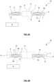
- FIGS. 1A to +5A and 8 show schematic cross sections through such a clamping device 10 according to the invention with a housing 3 which comprises two housing parts 3a, 3b, and with a spring 1 arranged in the housing 3, which spring comprises at least two annular elastic elements 1a, 1b according to the invention.
- the clamping device 10 comprises the following: a first elastic element 1a according to the invention and a second elastic element 1b according to the invention; a housing 3 comprising a first housing part 3a with an inner surface and a second housing part 3b with an inner surface, wherein the housing parts 3a, 3b are arranged and fastened to one another in such a way that the inner surfaces of the housing parts 3a, 3b together delimit an interior space 13 within the housing 3; one or more clamping elements 8, wherein each clamping element 8 has a clamping surface 7; a Spring 1 arranged in an interior space 13, comprising the first elastic element 1a and the second elastic element 1a, wherein the elastic elements 1a, 1b are arranged within the interior space 13 in such a way that a first pressure chamber 4 is formed in the interior space 13 between the elastic elements 1a, 1b and the inner surfaces of the housing parts 3a, 3b, wherein the first pressure chamber 4 can be vented and can be subjected to overpressure from a pressure medium that can be supplied to
- Each of these clamping devices 10 shows a closed state, with the clamping surface 7 of the clamping element 8 touching the periphery of the object 5.
- the clamping element 8 is also referred to as a clamping lip.
- the clamping element 8 can be formed integrally with the remaining parts of the housing part 3a, 3b or can be a component of the housing part 3a, 3b that is structurally separate from the remaining parts.
- the clamping force or effect of the clamping surface 7 on the object 5 to be clamped takes place in a clamping plane which is spanned by two vectors, each of which forms a radius of the annular elastic elements 1a, 1b or annular recess 11 (cf. Fig. 5A ).
- the axis 9 can pass through the center of the ring of the components described here as annular and can therefore be referred to as the main axis of the clamping device 10, which can run perpendicular to the clamping plane.
- the inner edge, projection, or end is closer to the axis 9 than the corresponding outer edge, projection, or end. The same can also apply to other components.
- the clamping device 10 can be designed rotationally symmetrical about this main axis 9
- the main axis 9 can run approximately or exactly centrally through an opening of the clamping device 10 (opening 14 in Fig. 5B ).
- the object 5 to be clamped for example a rotatable shaft of a machine or a table, is placed within the opening 14 and the clamping force of the clamping device is therefore directed radially inwards towards the main axis 9 (perpendicular to the main axis 9) within the clamping plane.
- Figures 1B , 4B the object 5 to be clamped is placed outside the clamping device 10 and the clamping force of the clamping device is therefore directed radially outwards away from the main axis 9 (perpendicular to the main axis 9) within the clamping plane.
- Fig. 1A , 2A , 3A , 4A The clamping element 8 is located between spring 1 and opening 14 or main axis 9.
- the object 5 to be clamped at least partially surrounds the clamping device 10, so that the clamping element 8 is located between the object 5 and the opening 14 or main axis 9.
- a component which at least partially fills the opening 14 and through which the main axis 9 extends can be introduced into the opening 14.
- venting an inner pressure chamber 2 of the spring 1 and ventilating an outer pressure chamber 4 can lead to at least partial relaxation of the spring 1 while the spring 1 presses against the radial contact surfaces, the distance between which increases slightly, so that the housing 3 is elastically deformed in the region of the clamping element 8 or the clamping surface 7 and the clamping surface 7 therefore touches the object 5 and is pressed against the object 5 with a (predefined) clamping force in order to clamp the object 5.
- the object 5 is clamped and the clamping device 10 is in the closed state, as in Figures 1A and 1B shown. In the closed state of the device 10, the spring 1 can still be slightly bent even after partial relaxation in order to be firmly fixed in the housing 3 in this state.
- the clamping element 8 can be an elastic element, such as a suspension fork, which In the pressure-free initial state of the device 10, the spring force of the (slightly) bent spring 1 moves it from an initial position in which the elastic element is relaxed into a tensioned position, for example by bending the spring fork 8, until, in the pressure-free initial state, an equilibrium is reached between a restoring force of the elastic element 8 and the spring force of the spring 1. In this equilibrium, the clamping surface 7 can press against the object 5.
- an elastic element such as a suspension fork
- the clamping device 10 can also be operated with a single pressure chamber, which can be, for example, the inner pressure chamber 2 or the outer pressure chamber 4.
- Figures 2A and 2B show the clamping devices 10 from the Figures 1A and 1B in each case in the open state in which the clamping surface 7 does not touch the circumference of the object 5 or is spaced from the circumference of the object 5.
- the inner pressure chamber 2 can be connected via an opening in the housing 3 to an air connection 11 (also referred to as "Open"), to which a compressed air pump 6 can be connected.
- an air connection 11 also referred to as "Open”
- the spring 1 By applying compressed air (for example 4 bar or 6 bar) to the inner pressure chamber 2 by the compressed air pump 6 and venting the outer pressure chamber 4, the spring 1 is, compared to the closed state of Fig. 1A, 1B , more strongly (convexly) bent or tensioned, resulting in a radial shortening of the spring 1 or the distance between the two contact surfaces.
- the clamping surface 7 lifts off the object 5 to release the clamping.
- the object 5 is freely movable (e.g., rotatable about axis 9 or linearly movable along axis 9) and the clamping device 10 is open.
- the device 10 can be switched back and forth between the closed state and the open state.
- Such pneumatic clamps 10 have a number of advantages over hydraulic clamps.
- a spring 1 with elastic elements 1a, 1b, and compressed air for example, very short reaction times are achieved when switching between the open and closed state and also a secure clamping of the object 5 is ensured.
- the spring 1 can preferably be designed in the shape of a plate, as in Fig. 5 shown in more detail, wherein two superimposed elastic elements 1a, 1b form the spring 1 and the inner pressure chamber 2 of the spring 1 between the plates 1a, 1b.
- the plates 1a, 1b can also be annular, as in Fig. 5 shown, and can optionally additionally have radial slots so that a change in the inner diameter is possible with particularly low forces.
- the elastic elements 1a, 1b can be coated with rubber, at least in the area of the slots, in order to create the tightness required for the compressed air.
- the elastic elements 1a, 1b are generally designed to be pressure-resistant and elastically bendable and are arranged in the housing 3 of the clamping device 10 in such a way that the inner pressure chamber 2 is formed between the elastic elements 1a, 1b within the spring 1 and the outer pressure chamber 4 is formed between each elastic element 1a, 1b and the housing 3 or the housing parts 3a, 3b of the clamping device 10.
- Figure 5 shows a three-dimensional view of a clamping device 10 similar to Figures 1A and 2A .
- the spring 1 By venting or applying compressed air to the outer pressure chamber 4 and venting the inner pressure chamber 2, as in Fig. 1A As shown, the spring 1 is at least partially relaxed and exerts a clamping force on the object 5 to be clamped, in particular on the circumference of a shaft 5. In the event of a power or pressure failure, the object 5 is clamped or the shaft 5 is immediately brought to a standstill, thus providing a safety clamp.
- such pneumatic clamps 10 can achieve holding torques of several 100 Nm and up to several 1000 Nm, which can be increased by additionally pressurizing the outer pressure chamber 4 with compressed air, as in Fig. 1A by a pressure pump 6 (booster).
- compressed air of a few bar is sufficient to provide several times the holding torque that is achieved without a booster.
- Pneumatic clamps also require lower costs and assembly effort than hydraulic clamps, and the use of compressed air eliminates any additional effort required to maintain cleanliness within the system.
- Such pneumatic clamps also allow for compact dimensions, as minimal transverse deflection and minimal (changes in) longitudinal expansion of the spring, and thus small pressure chamber volumes, are sufficient to generate the required clamping forces.
- spring 1 In the initial, pressureless state, spring 1 can be bent to varying degrees (transversely) and thus radially shortened to varying degrees.
- the interior of housing 3 can be adapted to the bending of elastic elements 1a, 1b or define it.
- a corresponding stop surface for elastic elements 1a, 1b can be formed, for example, by an inner housing wall.
- the inner housing wall can be designed to complement (e.g., concave) a bending (e.g., convex) of elastic elements 1a, 1b.
- the spring 1 is generally slightly elastically bent (e.g. convex) or pre-tensioned in the pressure-free initial state and the clamping devices 10 can be closed ( Fig. 1A, 1B ).
- the clamping device 10 is only opened by the application of force from the inside by applying compressed air to the inner pressure chamber 2 ( Fig. 2A, 2B ).
- the spring 1 In the initial pressure-free state, the spring 1 is usually slightly bent, so that in the event of a clamping action or in the event of a pressure drop, the spring force generated by the energy stored in the spring 1 is transferred to the object 5 to be clamped as a clamping force in order to clamp the object 5.
- the spring 1, with the same housing 3 can be more transversely curved outwards in the depressurized initial state and thus more radially shortened than with passive clamping devices.
- This smaller radial expansion of the elastic elements 1a, 1b in the depressurized initial state can lead to an open state of the clamping device 10 in the depressurized initial state.
- the elastic elements 1a, 1b are elastically bent and press against the contact surfaces so that the spring is fixed in the housing.
- the interior of the housing or the recesses can absorb the greater curvature caused by plastic deformation in the initial state.
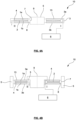
- the clamping force must now be actively induced from the outside, as in Fig. 4A and 4B shown to transfer the clamp into the closed state.
- compressed air is introduced into the external pressure chamber 4 by a compressed air pump 6, thus pressurizing the spring 1 from the outside in such a way that the spring 1 is actively relaxed, the curvature of the spring 1 is reduced, the distance between the two contact surfaces increases, and the housing 3 is elastically deformed in the area of the clamping element 8 or the clamping surface 7, so that the clamping surface 7 touches the object 5 and exerts a clamping force on the object 5, thereby clamping the object 5.
- the active clamping device 10 is then in the closed state.
- an active or passive clamping system 10 is used. If a safety clamp is primarily desired, a passive clamping device is generally used. With such pneumatic passive clamping systems, it is possible to generate a predetermined clamping force even in a depressurized state when the device is appropriately mounted in an overall device, which clamping force is applied to the object 5 to be clamped. By applying overpressure or negative pressure, the forces transmitted to this object can be increased, reduced, or completely eliminated, which opens up a wide variety of applications. If, on the other hand, the clamping device is primarily intended to carry out a deliberate work process, such as a tool change, an active clamping device is generally used.
- the housing 3 of the clamping devices 10 comprises two housing parts 3a, 3b, which are fastened to one another by fastening means, such as screws, and are mounted in such a way that, in the mounted state, the two housing parts 3a, 3b enclose the interior space 13 between the housing parts 3a, 3b within the Housing 3 defines the spring 1 together with its inventive annular elastic elements 1a, 1b.
- the housing parts 3a, 3b each define a recess 11, which is also annular and serves to receive the annular elastic elements 1a, 1b, as shown in Figures 5A to 5D shown.
- At least a part of the first contact surface 101 of the housing part can run (substantially) perpendicular to the radial direction R of the annular recess 11 and/or a part of the second contact surface 102 of the housing part can run (substantially perpendicular) to the radial direction R of the annular recess 11.
- the housing 3 Through the center of the housing 3 extends an opening 14 (Fig. 5B) into which the object 5 to be clamped, such as a shaft, can be inserted.
- the housing can extend up to 360° around this opening and at least partially encloses the object 5 in at least one plane, which is referred to as the clamping plane.
- the central main axis 9 of the clamping devices runs centrally through the opening 14 and perpendicular to the clamping plane.
- the main axis 9 runs centrally through the shaft along its longitudinal axis.
- the clamping surfaces 7 which, in the event of elastic deformation of the housing 3 in the region of the clamping element 8 or the clamping surface 7, exert the clamping force on the outer circumference of the object 5 and can thereby clamp the object 5.
- a symmetrical distribution of the clamping force along the clamping surface 7 or along the circumference of the object 5 is desirable.
- a non-symmetrical distribution of the clamping force can lead to damage to the object 5.
- one or both contact surfaces 101, 102 are circular within the clamping plane.
- the clamping surface 7 is circular within the clamping plane.
- the clamping element 8 can be annular. All ring-shaped or circular components described herein can, individually or in combination, have as their center the intersection point of the main axis 9 with the clamping plane (e.g. center point of the opening 14).
- Figure 5B shows an embodiment of the component according to the invention.
- the component comprises the annular elastic element 1a according to the invention and a housing part (here the upper housing part 3a made of Fig. 5A ), wherein the housing part 3a has an annular recess 11 for clamping the annular elastic element 1a, and wherein the housing part 3a has an inner surface defined by the recess 11 (cf. 105 in Fig. 7 ).
- the annular recess 11 preferably defines an annular opening 12 in the housing part, wherein the annular opening is formed between a first annular edge 12a of the housing part and a second annular edge 12b of the housing part.
- the elastic element 1a can be clamped between the first annular edge 12a and the second annular edge 12b.
- the elastic element 1a is in contact with the first side surface (cf. 16c in Fig. 6C ) facing the inner surface through the opening 12 into the recess 11 and is clamped in the recess 11, the first pressure chamber 4 is formed between the inner surface and the elastic element 1a.
- the elastic element according to the invention has the means mentioned above, which allow a reliable use of the component in a humid environment. These means are described in connection with the Figures 6 to 12 explained in more detail.
- the illustrated elastic element 1a of the spring 1 extends from a first contact surface 101 within the housing part 3a to a second contact surface 102 within the housing part 3a and can contact it.
- the first contact surface 101 is arranged radially further outward from the center of the opening 14 than the second contact surface 102.
- Figure 5C shows the section of the Figure 5B illustrated housing part 3a in which the upper plate 1a of the spring 1 meets the first contact surface 101 and is preferably in contact with it.
- Figure 5D shows the section of the Figure 5B illustrated housing part 3a in which the upper plate 1a of the spring 1 meets the second contact surface 102 and is preferably in contact with it.
- one or more further components it is also possible for one or more further components to be located radially between the elastic element 1a and one or more of the contact surfaces 101, 102, via which the elastic element 1a exerts its spring force on the contact surfaces 101, 102.
- the elastic element 1a is clamped in the recess 11 between the inner sides of the housing part 3a.
- Each of the plates of the spring 1 is inserted in the direction of the main axis 9 of the clamping devices 10 through the opening 12 into the recess 11 of the respective housing part during assembly along the inner surfaces of the housing part 3a, until the respective plate hits a stop 112, 122 at the end of each of the two contact surfaces 101, 102 and therefore cannot be inserted further into the recess 11. Since the expansion of the elastic element 1a in the clamping plane or in the radial direction of the annular recess can be greater than the expansion of the interior defined by the housing part, the plate 1a in the be bent or prestressed in the initial pressureless state.
- Figure 6A shows an annular elastic element 1a, 1b according to the invention for a clamping and/or braking device 10, the element 1a, 1b comprising: an annular spring plate 16, wherein the annular spring plate 16 has a first annular side surface 16c and a second annular side surface 16d; a first sealing element 17, wherein the first sealing element 17 is arranged on the first side surface 16c of the spring plate 16; a second sealing element 15, wherein the second sealing element 15 is arranged on the second side surface 16d of the spring plate 16, and wherein the second sealing element 15 forms an inner projection 15a in a region of an inner edge 16a of the annular spring plate 16 and an outer projection 15b in a region of an outer edge 16b of the annular spring plate 16, wherein the first sealing element 17 forms a first projection 17a.
- the Figures 6B and 6C show that the first projection 17a is formed between the inner 16a and outer edge 16b of the annular spring plate 16; here, for example, the first projection 17a is formed in a region of the inner 16a or outer 16b edge of the annular spring plate 16.
- Figures 6A and 6B further show that the first sealing element 17, preferably in a region of the outer edge 16b of the annular spring plate 16, forms an optional second projection 17b on the first side surface 16c.
- Each of the projections 15a, 15b, 17a, 17b of the first and/or second sealing element 15, 17 can be annular, at least in sections, and extend annularly around the axis 9.
- Each of the projections 15a, 15b, 17a, 17b of the first and/or second sealing element 15, 17 can be fixed to the spring plate 16, preferably vulcanized, or can be arranged detachably from the spring plate 16, preferably as an O-ring.
- Figures 6A and 6C also show that a longitudinal axis of the first projection 17a of the first sealing element 17 is (substantially) perpendicular to the first side surface 16c of the spring plate 16.
- the inner projection 15a and/or outer projection 15b of the second sealing element 15 each has an at least partially flat surface 15e, 15f, which serves as a bearing surface, for example, against an (inner) housing wall or another elastic element in order to delimit and seal the second pressure chamber 2.
- the inner and/or outer projection 15a, 15b of the second sealing element 15 each forms, at least in sections, a radially extending bulge 15c, 15d.
- the bulge 15d of the outer projection 15b of the second sealing element 15 extends as shown in Figure 6B shown, radially outward, preferably radially outward beyond the outer edge 16a of the spring plate 16.
- the bulge 15d is adjacent or contiguous to the flat surface 15f.
- the flat surface 15f merges into the bulge 15d.
- the bulge 15c of the inner projection 15a of the second sealing element 15 extends as shown in Figure 6C shown, radially inward, preferably radially inward beyond the inner edge 16a of the spring plate 16.
- the bulge 15c is adjacent or contiguous to the flat surface 15e.
- the flat surface 15e merges into the bulge 15c.
- the first sealing element 17 and/or the second sealing element 15 may individually or both be made of an elastic material, preferably rubber or another suitable material, which is fixed (e.g. vulcanized) on the spring plate 16.
- Figure 7 shows a housing part 3a, 3b of a component or device according to the invention, wherein the housing part 3a, 3b is an advantageous further development of the housing part 3a from Figure 5B
- the housing part also has advantageous and preferred adaptations.
- the first projection 17a of the first sealing element 17 will establish a preferably sealing contact with a first portion of the inner surface 105 of the housing part 3a, 3b.
- the first portion may comprise an indentation or depression 106 of the housing part 3a, 3b.
- the surface shapes of the first projection 17a and the first portion 106 are at least partially complementary in order to establish a particularly effective sealing contact.
- the second projection 17b of the first sealing element 17 will establish a preferably sealing contact with another section of the inner surface 105 of the housing part 3a, 3b.
- This other section can have an indentation or depression 107 of the housing part 3a, 3b.
- the surface shapes of the second projection 17b and the section 107 are at least partially complementary in order to establish a particularly effective sealing contact.
- Each of the two projections 17a, 17b inhibits or completely prevents a fluidic connection between the first pressure chamber 4 and the surroundings of the housing, particularly in the region of the transition between two adjacent housing parts 3a, 3b.
- the housing part 3a, 3b can comprise an annular recess 11 for clamping the annular elastic element 1a, 1b, wherein the recess 11 forms a first annular edge 12a and a second annular edge 12b of an annular opening 12 of the housing part 3a, 3b, wherein the annular recess 11 defines an inner surface 105 of the housing part 3a, 3b between the first annular edge 12a and the second annular edge 12b, wherein the inner surface 105 forms a first bevel 103 (or long chamfer) in the region of the first annular edge 12 and the inner surface 105 forms a second bevel 104 (or long chamfer) in the region of the second annular edge 12b, wherein the bevels 103, 104 are aligned such that the annular opening 12 enlarged towards the first and second edges 12a, 12b.
- the inner surface 105 can form a first contact surface 101 and a second contact surface 102, which are designed to clamp the spring plate 16 of the elastic element 1a, 1b according to the invention therebetween, wherein the first bevel 103 is arranged between the first contact surface 101 and the first annular edge 12a, and wherein the second bevel 104 is arranged between the second contact surface 102 and the second annular edge 12b.
- the elastic element 1a, 1b is clamped in the recess 11 with the first side surface 16c facing the inner surface 105, the bulges 15c, 15d are brought into preferably sealing contact with the bevels 103, 104.
- the first contact surface 101 can form a first bevel 103 (or called a long chamfer) or can merge into this and/or the second contact surface 102 can form a second bevel 104 (or called a long chamfer) or can merge into this, wherein the bevels 103, 104 are each preferably aligned such that the annular opening 12 or the recess 11 increases in size towards the first and second edges 12a, 12b (cf. Fig. 7 and 5B ).
- Each of these bevels 103, 104 largely prevents the The bending force of the clamping element 8 is not transmitted by the second sealing element 15 to the clamping element 8, but rather the spring plate 16, or the inner edge 16a, primarily transmits the force for clamping or braking the object 5 to the clamping element 8 and the clamping surface 7. This protects the second sealing element 15 and makes the process of opening and closing the device more reliable.
- bulges 15c, 15d are provided, which fill the space at the bevels and come into contact with bevels 103, 104.
- Bulges 15c, 15d are advantageous for the tightness of the first pressure chamber 4 against the gap at the transition of the clamping elements 8 of adjacent housing parts 3a, 3b.
- the bulges at the housing edge with bevels 103, 104 are advantageous in that little or no medium flows in or out over the housing edge during operation of the first pressure chamber 4.
- the flat surfaces 15e, 15f increase, on the one hand, the resistance to the permeability of a pressure medium (especially gases) when the second pressure chamber 2 is pressurized with the pressure medium.
- the flat surfaces 15e, 15f reduce or prevent the overflow of a medium between the first pressure chamber 4 and the second pressure chamber 2.
- the flat surfaces 15f and 15e also support the displacement of the bulges 15c, 15d against the bevels 103, 104 on the housing and thus the effects of the bulges described above. This support is particularly pronounced when, as in connection with the Figures 6B and 6C As described, the flat surface 15e or 15f is adjacent to the associated bulge 15c or 15d and/or merges into it.
- each of the sealing elements 17a and 17b is to be regarded as an additional barrier and supports the tightness of the first pressure chamber 4 against the environment.
- the housing part 3a, 3b can have a preferably circular groove or notch 110 for receiving an O-ring.
- the groove or notch 110 can preferably completely encircle the housing part 3a, 3b along the circumference of the housing part in the region of the first annular edge 12a, or between an outer edge 100b of the housing part and the first contact surface 101 or the recess 11.
- the groove or notch 110 can alternatively or additionally encircle the housing part 3a, 3b along the circumference of the housing part in the region of the second annular edge 12b, or between an inner edge 100a of the Housing part and the second contact surface 102 or the recess 11, preferably completely.
- Figure 8 shows a clamping and/or braking device 10 according to the invention.
- Figure 8 is an example of a device 10 with an inwardly directed clamping effect as in the Figures 1A , 2A and 5A shown.
- the first projection 17a of the first sealing element 17 of at least one of the elastic elements 1a, 1b establishes a preferably sealing contact with a first portion (e.g., 106) of the inner surface 105 of one of the housing parts 3a, 3b, in order to at least inhibit a flow connection between a region of the first pressure chamber 4 and a transition between the housing parts 3a, 3b.
- the contact can be at least partially sealing against a medium, preferably a fluid or liquid, which penetrates from outside the device 10 through the gap at the transition between the housing parts 3a, 3b or clamping elements 8 into the housing 3.
- the area of the first pressure chamber 4 is in Figure 8 between the first projection 17a of the first sealing element 17 of the at least one elastic element 1a, 1b and the outer edge 16b of the spring plate 16 of the at least one elastic element 1a, 1b, or the second projection 17b of the first sealing element 17 of the at least one elastic element.
- the optional second projection 17b of the first sealing element 17 of at least one of the elastic elements 1a, 1b establishes contact with a second section (e.g. 107) of the inner surface 105 of the housing part 3a, 3b, wherein the second section of the inner surface 105 preferably lies between the first contact surface 101 and the second contact surface 102 of the housing part 3a, 3b.
- This projection can also reduce the fluidic connection of the first pressure chamber 4 with the area outside the clamping element 8.
- the inner surface 105 can have one or more indentations or depressions 106, 107, wherein the indentation or depression 106, 107 is preferably complementary in shape to the surface of the projection 17a, 17b contacting it.
- first contact surface 101 of each housing part 3a, 3b forms the first bevel 103 and the second contact surface 102 of each housing part 3a, 3b forms the second bevel 104, wherein the bulge 15c of the inner projection 15a of the second sealing element 15 of the first elastic element touches the second slope 104 of the second contact surface 102 of the housing part 3a, 3b, and wherein the bulge 15d of the outer projection 15b of the second sealing element 15 of the first elastic element touches the first slope 103 of the first contact surface 101 of the housing part 3a, 3b.
- the first elastic element 1a and the second elastic element 1b are in Figure 8 are clamped in the interior space 13 in such a way that the flat surfaces 15e of the inner projections 15a of the second sealing element 15 of the elastic elements 1a, 1b touch each other and/or the flat surfaces 15f of the outer projections 15b of the second sealing elements of the elastic elements 1a, 1b touch each other, in order to delimit the second pressure chamber 2 and to seal it, in particular during its application with pressure medium.
- Figure 9 shows an embodiment of the elastic element 1a, 1b according to the invention with a first connection seal 30 and/or a second connection seal 20.
- the annular spring plate 16 may be disposed between a portion of the second connection seal 20 and a portion of the first connection seal 30.
- the first connection seal 30 and the second connection seal 20 may be disposed on opposite portions of the inner edge 16a or outer edge 16b of the annular spring plate 16.
- the first connection seal 30 and/or the second connection seal 20 can each be made of an elastic material, preferably rubber.
- the first connection seal 30 can be offset at least in sections radially inwardly or outwardly relative to the inner edge 16a and/or outer edge 16b (cf. Fig. 9 ) of the spring plate 16 of the elastic element 1a, 1b.
- the first connection seal 30 can be part of the first sealing element 17 and/or the second sealing element 15.
- the first connection seal 30 can extend radially over the inner edge 16a or the outer edge 16b (cf. Fig. 9 ) protrude beyond.
- the second connection seal 20 can be offset at least in sections radially inwards or outwards relative to the inner edge 16a and/or outer edge 16b (cf. Fig. 9 ) of the spring plate 16 of the elastic element 1a, 1b.
- the second connection seal 20 can be part of the first sealing element 17 and/or the second sealing element 15
- the second connection seal 20 can be radially arranged over the inner edge 16a or the outer edge 16b (cf. Fig. 9 ) protrude beyond.
- the Figures 11 and 12 each show a section of the cross-section of the device 10 according to the invention.
- the left half and the right half of the Figures 11 and 12 each show a cross section of the elastic element 1a, 1b according to the invention according to Figure 9 installed in the housing part 3a, 3b according to Figure 10 .
- the elastic element 1a, 1b is clamped in the recess 11 between the inner edge 100a (or clamping element 8 with clamping surface 7) and the outer edge 100b of the housing part 3a, 3b in such a way that the first connection seal 30 comes into contact with the area of the housing part 3a, 3b for the first connection I and the second connection seal 20 comes into contact with the area of the housing part 3a, 3b for the connection II.
- This is carried out twice, so that two components according to the invention are prepared, which are then fastened together, as in the Figures 11 and 12 shown.
- the Figure 11 The section of the cross-section of the device 10 shown corresponds in its position to the Figures 9 and 10 indicated sections XI through the elastic element 1a, 1b and the housing part 3a, 3b in the region of the second connection seal 20.
- the second connection seal 20 has an edge along a second connection opening, wherein the edge serves to seal the second connection II of the clamping and/or braking device 10 for pressurizing the second pressure chamber 2 of the clamping and/or braking device 10 with a pressure medium.
- the second connection seal 20 forms a connection projection 21 along the edge of the second connection opening, which connection projection encircles the second connection opening at least partially and preferably completely.
- connection projection 21 of the second connection seal 20 forms a recess 22, at least in sections, on the edge of the second connection opening to reinforce the seal, particularly against the escape of pressure medium into the environment.
- the recess 22 of the second connection seal 20 reduces the risk of the second connection seal 20 lifting off the housing's flat surface, especially when pressurizing the first pressure chamber 4.
- the recess 22 avoids the use of sealing compound (adhesive) at this point. Such a sealing compound could have a negative impact on the vacuum or clean room.
- the second connection seal 20 may form a part of the inner or outer projection 15a, 15b of the second sealing element 15.
- the part of the projection of the second sealing element 15 formed by the second connection seal 20 may be a side of the second connection opening 20 which is remote from and/or opposite a side of the second connection opening 20 on which the connection projection 21 is formed by the second connection seal 20.
- the Figure 12 The section of the cross-section of the device 10 shown corresponds in its position to the Figures 9 and 10 indicated sections XII through the elastic element 1a, 1b and the housing part 3a, 3b in the region of the first connection seal 30.
- the first connection seal 30 has an edge of a first connection opening, wherein the edge serves to seal the first connection I of the clamping and/or braking device 10 for pressurizing the first pressure chamber 4 of the clamping and/or braking device 10 with a pressure medium.
- the edge of the first connection seal 30 surrounds the first connection opening at least partially and preferably completely.
- the first connection seal 30 can comprise an O-ring that surrounds the first connection opening.
- the bulge 15d of the projection 15b with the bevel 103, together with the first connection seal 30 at connection I, ensure that no fluids flow in or out over the housing edge when the first pressure chamber 4 is pressurized. In addition, this eliminates the need for unwanted sealing compounds (adhesives) between the housing halves. Such a sealing compound could have a negative impact on the vacuum or clean room.
- terminals can be provided that can be operated reliably in humid environments and can also optionally be operated in a vacuum or in a clean room without negatively affecting the dynamics of opening and closing the terminal.
Landscapes
- Engineering & Computer Science (AREA)
- General Engineering & Computer Science (AREA)
- Mechanical Engineering (AREA)
- Clamps And Clips (AREA)
- Gasket Seals (AREA)
- Braking Arrangements (AREA)
Priority Applications (9)
| Application Number | Priority Date | Filing Date | Title |
|---|---|---|---|
| ES23177172T ES3038428T3 (en) | 2023-06-05 | 2023-06-05 | Device for clamping and/or braking damp environments |
| EP23177172.6A EP4474103B1 (de) | 2023-06-05 | 2023-06-05 | Klemm- und/oder bremsvorrichtung für feuchte umgebungen |
| US18/993,322 US12584531B2 (en) | 2023-06-05 | 2024-04-22 | Clamping and/or braking device for humid environments |
| CN202480003339.9A CN119522150A (zh) | 2023-06-05 | 2024-04-22 | 用于潮湿环境的夹紧和/或制动装置 |
| JP2024576413A JP7842261B2 (ja) | 2023-06-05 | 2024-04-22 | 高湿度環境のためのクランプ及び/又はブレーキ装置 |
| CA3260054A CA3260054A1 (en) | 2023-06-05 | 2024-04-22 | CLAMPING AND/OR BRAKING DEVICE FOR HUMID ENVIRONMENTS |
| KR1020257001801A KR102903961B1 (ko) | 2023-06-05 | 2024-04-22 | 습한 환경용 클램핑 및/또는 제동 장치 |
| PCT/EP2024/060861 WO2024251424A1 (de) | 2023-06-05 | 2024-04-22 | Klemm- und/oder bremsvorrichtung für feuchte umgebungen |
| TW113119584A TWI919279B (zh) | 2023-06-05 | 2024-05-27 | 用於潮濕環境的夾持和/或制動裝置 |
Applications Claiming Priority (1)
| Application Number | Priority Date | Filing Date | Title |
|---|---|---|---|
| EP23177172.6A EP4474103B1 (de) | 2023-06-05 | 2023-06-05 | Klemm- und/oder bremsvorrichtung für feuchte umgebungen |
Publications (3)
| Publication Number | Publication Date |
|---|---|
| EP4474103A1 EP4474103A1 (de) | 2024-12-11 |
| EP4474103C0 EP4474103C0 (de) | 2025-05-21 |
| EP4474103B1 true EP4474103B1 (de) | 2025-05-21 |
Family
ID=86692937
Family Applications (1)
| Application Number | Title | Priority Date | Filing Date |
|---|---|---|---|
| EP23177172.6A Active EP4474103B1 (de) | 2023-06-05 | 2023-06-05 | Klemm- und/oder bremsvorrichtung für feuchte umgebungen |
Country Status (8)
| Country | Link |
|---|---|
| US (1) | US12584531B2 (ja) |
| EP (1) | EP4474103B1 (ja) |
| JP (1) | JP7842261B2 (ja) |
| KR (1) | KR102903961B1 (ja) |
| CN (1) | CN119522150A (ja) |
| CA (1) | CA3260054A1 (ja) |
| ES (1) | ES3038428T3 (ja) |
| WO (1) | WO2024251424A1 (ja) |
Families Citing this family (1)
| Publication number | Priority date | Publication date | Assignee | Title |
|---|---|---|---|---|
| ES3037699T3 (en) * | 2023-06-05 | 2025-10-06 | Hema Maschinen Und Apparateschutz Gmbh | Vacuum-compatible clamping and/or braking device |
Family Cites Families (25)
| Publication number | Priority date | Publication date | Assignee | Title |
|---|---|---|---|---|
| US3753478A (en) | 1971-07-19 | 1973-08-21 | Borg Warner | Clutch with fluid operated lock |
| DE69100636T2 (de) | 1990-02-09 | 1994-05-26 | Bo Kungsoer Granbom | Bremsvorrichtung in einer gradlinigen Bewegungsvorrichtung. |
| US5836233A (en) | 1997-03-07 | 1998-11-17 | Rumsey; Donald | Spring brake with sealable breather holes |
| ATE280011T1 (de) * | 1999-07-14 | 2004-11-15 | Erowa Ag | Einrichtung zum positionsdefinierten aufspannen eines werkstücks im arbeitsbereich einer bearbeitungsmaschine |
| US6629584B1 (en) | 1999-11-11 | 2003-10-07 | Innotech Engineering Gmbh | Clamping and/or braking device |
| DE10203008B4 (de) | 2002-01-26 | 2011-11-17 | Horst Jansen | Druckspeicherblase für gasförmige oder flüssige Druckmedien |
| KR101067554B1 (ko) | 2003-01-20 | 2011-09-27 | 클라우스 호프만 | 클램핑 및/또는 제동 장치 |
| DE10335795A1 (de) | 2003-08-05 | 2005-03-10 | Klaus Hofmann | Klemm- und/oder Bremsvorrichtung |
| DE102004010987B4 (de) * | 2004-03-03 | 2013-08-22 | Klaus Hofmann | Sicherungseinheit |
| EP1629939A1 (en) | 2004-08-23 | 2006-03-01 | Peter Lehmann AG | Brake, particularly for rotating tables |
| DE102005033468A1 (de) | 2005-07-18 | 2007-01-25 | Klaus Hofmann | Spannvorrichtung |
| DE102009014117A1 (de) | 2009-03-24 | 2010-10-07 | Peiseler Gmbh & Co. Kg | Klemmvorrichtung |
| FR2958986B1 (fr) | 2010-04-19 | 2012-05-11 | Poclain Hydraulics Ind | Frein multiplicateur d'effort |
| KR101346464B1 (ko) * | 2012-02-01 | 2014-01-16 | 박동수 | 고속 고효율 엔씨 인덱스 테이블 |
| CN102678786A (zh) | 2012-05-28 | 2012-09-19 | 北京信息科技大学 | 一种回转制动装置 |
| DE102012212889A1 (de) * | 2012-07-23 | 2014-01-23 | Robert Bosch Gmbh | Dichtungsring für ein Pumpenelement einer Fahrzeugbremsanlage |
| CN203412996U (zh) * | 2013-03-13 | 2014-01-29 | 大连光洋科技工程有限公司 | 气动钳夹 |
| CN107127360A (zh) | 2017-05-04 | 2017-09-05 | 广州市霏鸿机电科技有限公司 | 一种气动式机床转轴刹车装置 |
| DE102019005799A1 (de) * | 2019-08-17 | 2021-02-18 | Sauter Feinmechanik Gmbh | Drehtisch |
| CN111322341B (zh) | 2020-03-10 | 2021-05-11 | 季华实验室 | 空气弹簧、空气弹簧的控制系统和控制方法 |
| DE102021006219B3 (de) * | 2021-12-16 | 2022-12-15 | Günther Zimmer | Brems- und/oder Klemmvorrichtung mit kolbenbelastbarem Scheibenelement |
| CN115325086B (zh) | 2022-08-23 | 2025-05-27 | 上海大学 | 一种刚度和阻尼可调的新型组合减振装置 |
| WO2024188534A1 (de) * | 2023-03-15 | 2024-09-19 | Hema Maschinen- Und Apparateschutz Gmbh | Gehäuseteil für eine pneumatische klemm- und/oder bremsvorrichtung |
| KR102867407B1 (ko) * | 2023-03-15 | 2025-09-30 | 헤마 마쉬넨 운트 아파라테슈츠 게엠베하 | 공압 클램핑 및/또는 제동장치 |
| ES3037699T3 (en) * | 2023-06-05 | 2025-10-06 | Hema Maschinen Und Apparateschutz Gmbh | Vacuum-compatible clamping and/or braking device |
-
2023
- 2023-06-05 ES ES23177172T patent/ES3038428T3/es active Active
- 2023-06-05 EP EP23177172.6A patent/EP4474103B1/de active Active
-
2024
- 2024-04-22 CN CN202480003339.9A patent/CN119522150A/zh active Pending
- 2024-04-22 US US18/993,322 patent/US12584531B2/en active Active
- 2024-04-22 KR KR1020257001801A patent/KR102903961B1/ko active Active
- 2024-04-22 WO PCT/EP2024/060861 patent/WO2024251424A1/de not_active Ceased
- 2024-04-22 JP JP2024576413A patent/JP7842261B2/ja active Active
- 2024-04-22 CA CA3260054A patent/CA3260054A1/en active Pending
Also Published As
| Publication number | Publication date |
|---|---|
| KR20250036817A (ko) | 2025-03-14 |
| US20250243916A1 (en) | 2025-07-31 |
| JP2025524282A (ja) | 2025-07-28 |
| CN119522150A (zh) | 2025-02-25 |
| US12584531B2 (en) | 2026-03-24 |
| TW202507159A (zh) | 2025-02-16 |
| JP7842261B2 (ja) | 2026-04-07 |
| EP4474103C0 (de) | 2025-05-21 |
| ES3038428T3 (en) | 2025-10-13 |
| EP4474103A1 (de) | 2024-12-11 |
| KR102903961B1 (ko) | 2025-12-23 |
| WO2024251424A1 (de) | 2024-12-12 |
| CA3260054A1 (en) | 2025-04-04 |
Similar Documents
| Publication | Publication Date | Title |
|---|---|---|
| DE102008018210B4 (de) | Dichtungsanordnung und nasslaufende Doppelkupplungsanordnung mit einer Dichtungsanordnung | |
| DE102011101968B4 (de) | Fluiddruckvorrichtung | |
| DE2609446A1 (de) | Kugelventil | |
| EP4474101B1 (de) | Vakuumtaugliche klemm- und/oder bremsvorrichtung | |
| WO2024188559A1 (de) | Pneumatische klemm- und/oder bremsvorrichtung | |
| WO2024188534A1 (de) | Gehäuseteil für eine pneumatische klemm- und/oder bremsvorrichtung | |
| EP4474103B1 (de) | Klemm- und/oder bremsvorrichtung für feuchte umgebungen | |
| DE2108705A1 (en) | High pressure control valve - esp for pneumatic or hydraulic circuits has nonstick sea | |
| DE9403963U1 (de) | Dichtungselement | |
| DE202023101258U1 (de) | Gehäuseteil für eine pneumatische Klemm- und/oder Bremsvorrichtung | |
| EP4431228B1 (de) | Gehäuseteil für eine pneumatische klemm- und/oder bremsvorrichtung | |
| DE3727173C2 (ja) | ||
| EP4431229B1 (de) | Pneumatische klemm- und/oder bremsvorrichtung | |
| EP4552792B1 (de) | Elastisches element für eine klemm- und/oder bremsvorrichtung | |
| DE102023005515B4 (de) | Elastisches Element | |
| EP4565388B1 (de) | Gehäuseteil für eine klemm- und/oder bremsvorrichtung | |
| EP4556160B1 (de) | Kit für eine klemm- und/oder bremsvorrichtung | |
| WO2025098651A1 (de) | Elastisches element für eine klemm- und/oder bremsvorrichtung | |
| DE102023131087B3 (de) | Komponenten für eine Klemm- und/oder Bremsvorrichtung | |
| DE202023106554U1 (de) | Elastisches Element für eine Klemm- und/oder Bremsvorrichtung | |
| DE202023106553U1 (de) | Komponenten für eine Klemm- und/oder Bremsvorrichtung | |
| DE102023122783A1 (de) | Gehäuseteil für eine Klemm- und/oder Bremsvorrichtung | |
| DE3303877C2 (de) | Einzelstempelventil | |
| DE202023104835U1 (de) | Gehäuseteil für eine Klemm- und/oder Bremsvorrichtung | |
| WO2025103616A1 (de) | Käfig für eine klemm- und/oder bremsvorrichtung |
Legal Events
| Date | Code | Title | Description |
|---|---|---|---|
| PUAI | Public reference made under article 153(3) epc to a published international application that has entered the european phase |
Free format text: ORIGINAL CODE: 0009012 |
|
| STAA | Information on the status of an ep patent application or granted ep patent |
Free format text: STATUS: EXAMINATION IS IN PROGRESS |
|
| 17P | Request for examination filed |
Effective date: 20240417 |
|
| AK | Designated contracting states |
Kind code of ref document: A1 Designated state(s): AL AT BE BG CH CY CZ DE DK EE ES FI FR GB GR HR HU IE IS IT LI LT LU LV MC ME MK MT NL NO PL PT RO RS SE SI SK SM TR |
|
| GRAP | Despatch of communication of intention to grant a patent |
Free format text: ORIGINAL CODE: EPIDOSNIGR1 |
|
| STAA | Information on the status of an ep patent application or granted ep patent |
Free format text: STATUS: GRANT OF PATENT IS INTENDED |
|
| INTG | Intention to grant announced |
Effective date: 20250130 |
|
| GRAS | Grant fee paid |
Free format text: ORIGINAL CODE: EPIDOSNIGR3 |
|
| GRAA | (expected) grant |
Free format text: ORIGINAL CODE: 0009210 |
|
| STAA | Information on the status of an ep patent application or granted ep patent |
Free format text: STATUS: THE PATENT HAS BEEN GRANTED |
|
| AK | Designated contracting states |
Kind code of ref document: B1 Designated state(s): AL AT BE BG CH CY CZ DE DK EE ES FI FR GB GR HR HU IE IS IT LI LT LU LV MC ME MK MT NL NO PL PT RO RS SE SI SK SM TR |
|
| REG | Reference to a national code |
Ref country code: GB Ref legal event code: FG4D Free format text: NOT ENGLISH |
|
| REG | Reference to a national code |
Ref country code: CH Ref legal event code: EP |
|
| REG | Reference to a national code |
Ref country code: DE Ref legal event code: R096 Ref document number: 502023001020 Country of ref document: DE |
|
| REG | Reference to a national code |
Ref country code: IE Ref legal event code: FG4D Free format text: LANGUAGE OF EP DOCUMENT: GERMAN |
|
| U01 | Request for unitary effect filed |
Effective date: 20250521 |
|
| U07 | Unitary effect registered |
Designated state(s): AT BE BG DE DK EE FI FR IT LT LU LV MT NL PT RO SE SI Effective date: 20250528 |
|
| U20 | Renewal fee for the european patent with unitary effect paid |
Year of fee payment: 3 Effective date: 20250624 |
|
| PGFP | Annual fee paid to national office [announced via postgrant information from national office to epo] |
Ref country code: ES Payment date: 20250710 Year of fee payment: 3 |
|
| PG25 | Lapsed in a contracting state [announced via postgrant information from national office to epo] |
Ref country code: GR Free format text: LAPSE BECAUSE OF FAILURE TO SUBMIT A TRANSLATION OF THE DESCRIPTION OR TO PAY THE FEE WITHIN THE PRESCRIBED TIME-LIMIT Effective date: 20250822 Ref country code: NO Free format text: LAPSE BECAUSE OF FAILURE TO SUBMIT A TRANSLATION OF THE DESCRIPTION OR TO PAY THE FEE WITHIN THE PRESCRIBED TIME-LIMIT Effective date: 20250821 |
|
| REG | Reference to a national code |
Ref country code: ES Ref legal event code: FG2A Ref document number: 3038428 Country of ref document: ES Kind code of ref document: T3 Effective date: 20251013 |
|
| PG25 | Lapsed in a contracting state [announced via postgrant information from national office to epo] |
Ref country code: PL Free format text: LAPSE BECAUSE OF FAILURE TO SUBMIT A TRANSLATION OF THE DESCRIPTION OR TO PAY THE FEE WITHIN THE PRESCRIBED TIME-LIMIT Effective date: 20250521 |
|
| PG25 | Lapsed in a contracting state [announced via postgrant information from national office to epo] |
Ref country code: HR Free format text: LAPSE BECAUSE OF FAILURE TO SUBMIT A TRANSLATION OF THE DESCRIPTION OR TO PAY THE FEE WITHIN THE PRESCRIBED TIME-LIMIT Effective date: 20250521 |
|
| PG25 | Lapsed in a contracting state [announced via postgrant information from national office to epo] |
Ref country code: RS Free format text: LAPSE BECAUSE OF FAILURE TO SUBMIT A TRANSLATION OF THE DESCRIPTION OR TO PAY THE FEE WITHIN THE PRESCRIBED TIME-LIMIT Effective date: 20250821 |
|
| PG25 | Lapsed in a contracting state [announced via postgrant information from national office to epo] |
Ref country code: IS Free format text: LAPSE BECAUSE OF FAILURE TO SUBMIT A TRANSLATION OF THE DESCRIPTION OR TO PAY THE FEE WITHIN THE PRESCRIBED TIME-LIMIT Effective date: 20250921 |
|
| PG25 | Lapsed in a contracting state [announced via postgrant information from national office to epo] |
Ref country code: SM Free format text: LAPSE BECAUSE OF FAILURE TO SUBMIT A TRANSLATION OF THE DESCRIPTION OR TO PAY THE FEE WITHIN THE PRESCRIBED TIME-LIMIT Effective date: 20250521 |
|
| PG25 | Lapsed in a contracting state [announced via postgrant information from national office to epo] |
Ref country code: CZ Free format text: LAPSE BECAUSE OF FAILURE TO SUBMIT A TRANSLATION OF THE DESCRIPTION OR TO PAY THE FEE WITHIN THE PRESCRIBED TIME-LIMIT Effective date: 20250521 |
|
| PG25 | Lapsed in a contracting state [announced via postgrant information from national office to epo] |
Ref country code: SK Free format text: LAPSE BECAUSE OF FAILURE TO SUBMIT A TRANSLATION OF THE DESCRIPTION OR TO PAY THE FEE WITHIN THE PRESCRIBED TIME-LIMIT Effective date: 20250521 |
|
| PG25 | Lapsed in a contracting state [announced via postgrant information from national office to epo] |
Ref country code: MC Free format text: LAPSE BECAUSE OF FAILURE TO SUBMIT A TRANSLATION OF THE DESCRIPTION OR TO PAY THE FEE WITHIN THE PRESCRIBED TIME-LIMIT Effective date: 20250521 |
|
| PLBE | No opposition filed within time limit |
Free format text: ORIGINAL CODE: 0009261 |
|
| STAA | Information on the status of an ep patent application or granted ep patent |
Free format text: STATUS: NO OPPOSITION FILED WITHIN TIME LIMIT |
|
| REG | Reference to a national code |
Ref country code: CH Ref legal event code: L10 Free format text: ST27 STATUS EVENT CODE: U-0-0-L10-L00 (AS PROVIDED BY THE NATIONAL OFFICE) Effective date: 20260402 |
|
| PG25 | Lapsed in a contracting state [announced via postgrant information from national office to epo] |
Ref country code: IE Free format text: LAPSE BECAUSE OF NON-PAYMENT OF DUE FEES Effective date: 20250605 |