EP4474004A1 - Vorrichtung zur behandlung durch phototherapie - Google Patents
Vorrichtung zur behandlung durch phototherapie Download PDFInfo
- Publication number
- EP4474004A1 EP4474004A1 EP24180045.7A EP24180045A EP4474004A1 EP 4474004 A1 EP4474004 A1 EP 4474004A1 EP 24180045 A EP24180045 A EP 24180045A EP 4474004 A1 EP4474004 A1 EP 4474004A1
- Authority
- EP
- European Patent Office
- Prior art keywords
- helmet
- shell wall
- headband
- user
- outer shell
- Prior art date
- Legal status (The legal status is an assumption and is not a legal conclusion. Google has not performed a legal analysis and makes no representation as to the accuracy of the status listed.)
- Pending
Links
Images

Classifications
-
- A—HUMAN NECESSITIES
- A61—MEDICAL OR VETERINARY SCIENCE; HYGIENE
- A61N—ELECTROTHERAPY; MAGNETOTHERAPY; RADIATION THERAPY; ULTRASOUND THERAPY
- A61N5/00—Radiation therapy
- A61N5/06—Radiation therapy using light
- A61N5/0613—Apparatus adapted for a specific treatment
- A61N5/0616—Skin treatment other than tanning
- A61N5/0617—Hair treatment
-
- A—HUMAN NECESSITIES
- A61—MEDICAL OR VETERINARY SCIENCE; HYGIENE
- A61N—ELECTROTHERAPY; MAGNETOTHERAPY; RADIATION THERAPY; ULTRASOUND THERAPY
- A61N5/00—Radiation therapy
- A61N5/06—Radiation therapy using light
- A61N2005/0635—Radiation therapy using light characterised by the body area to be irradiated
- A61N2005/0643—Applicators, probes irradiating specific body areas in close proximity
- A61N2005/0645—Applicators worn by the patient
- A61N2005/0647—Applicators worn by the patient the applicator adapted to be worn on the head
-
- A—HUMAN NECESSITIES
- A61—MEDICAL OR VETERINARY SCIENCE; HYGIENE
- A61N—ELECTROTHERAPY; MAGNETOTHERAPY; RADIATION THERAPY; ULTRASOUND THERAPY
- A61N5/00—Radiation therapy
- A61N5/06—Radiation therapy using light
- A61N2005/065—Light sources therefor
- A61N2005/0651—Diodes
-
- A—HUMAN NECESSITIES
- A61—MEDICAL OR VETERINARY SCIENCE; HYGIENE
- A61N—ELECTROTHERAPY; MAGNETOTHERAPY; RADIATION THERAPY; ULTRASOUND THERAPY
- A61N5/00—Radiation therapy
- A61N5/06—Radiation therapy using light
- A61N2005/0658—Radiation therapy using light characterised by the wavelength of light used
- A61N2005/0662—Visible light
- A61N2005/0663—Coloured light
Definitions
- the present invention relates to a phototherapy treatment device for an external region of the body of a living being. More particularly but not exclusively, it applies to phototherapy treatment of the head surface of a user, for example to treatment of the scalp as a treatment for baldness.
- the treatment consists of applying light radiation with a predefined emission spectrum directly to the scalp.
- This phototherapy treatment can also be applied in combination with a photosensitizing product applied to the area to be treated a few hours before exposure to the light radiation to increase the effectiveness of the treatment.
- dynamic phototherapy also known by the English acronym PDT "Photo Dynamic Therapy”
- the radiation is preferably substantially monochromatic or has an emission spectrum within a relatively narrow band of wavelengths.
- the emission spectrum includes a peak wavelength in red visible light or blue visible light, these wavelengths having demonstrated particular efficacy for the treatment of certain skin conditions.
- phototherapy treatment in a predefined wavelength range can have a beneficial effect on many skin problems, such as scars, stretch marks, acne, wrinkles and fine lines.
- the cells in the irradiated region will react according to a principle similar to that of plant photosynthesis.
- the light will stimulate the cells, and more specifically certain cellular structures of the cell, such as the mitochondria.
- ATP acronym for Adenosine Tri Phosphate
- red light for example at the wavelength of 630 nm, allows stimulation of hair regrowth, improvement of hair quality and density as well as stabilization of hair loss.
- equipment for phototherapy treatment of the scalp of a user comprising a helmet delimiting an open end through which, in the position of use, the user's head is at least partially engaged.
- one of the proposed solutions is to hold the helmet using ear units that enclose the head on each side at ear level, as in the patent application. EP2477697 .
- This solution has the disadvantage of disturbing the user's sound environment during their phototherapy treatment, which is a disadvantage when the user wishes to participate, for example, in a conversation with an interlocutor.
- Another solution is to provide a chin strap that holds the helmet at the user's chin.
- the present invention aims in particular to propose a phototherapy device which overcomes its drawbacks.
- the invention relates to a helmet for treating a user's scalp by phototherapy, the helmet comprising outer and inner shell walls each extending from a proximal top portion to a distal edge and defining, once assembled, a peripheral edge of the helmet which delimits an opening for the passage of the user's head and a light source arranged between the two walls emitting towards the inside of the helmet, characterized in that it comprises a circumferential headband for adjusting the helmet to a head circumference of the user, attached to the peripheral edge, said headband comprising a body provided with a deformation portion extending radially towards the inside of the helmet and being configured to deform between a rest position deployed radially towards the inside of the helmet and a compressed position between the helmet and the user's head in the use configuration.
- a helmet according to the invention may include one or more of the features following.
- the deformation portion is hollow.
- the headband is mounted on the helmet such that the headband cannot be removed before the two shell walls are disassembled from each other.
- the deformation portion extends towards the inside of the helmet by a connecting bead which is pinched between reliefs of the distal edges of the shell walls.
- the inner wall comprises on its rear face a circumferentially projecting rib which forms a support shoulder at the distal edge such that the bead is gripped inside this shoulder by the inner shell wall against a relief of the outer shell wall.
- the distal edge of the outer shell wall is folded at an inwardly projecting end to form a flange extending radially inward to form a bearing shoulder such that the bead is gripped inside this shoulder by the outer shell wall against a relief of the inner shell wall.
- the deformation portion extends towards the outside of the helmet by an external anchoring heel which is retained by a relief provided on a rear face of the external shell wall.
- the anchor heel is formed by a free end edge curved into a U shape which fits radially into a circumferential groove provided on an outer face of the outer shell wall.
- the adjustment strip is configured to be pre-positioned by being releasably retained on the outer shell wall in a final destination position, prior to assembly of the inner shell wall to the outer shell wall to lock the strip in said position.
- the headband is made of a deformable and resilient material with a shore A hardness of between 25 and 95 shore.
- the helmet includes a heat dissipation interface plate made of a light-opaque material that extends between the two shell walls.
- the headband the outer shell wall being made of translucent materials
- the outer shell wall has on its distal edge a locally thickened pattern which locally prevents light from passing so as to produce a light pattern.
- the two shell walls are assembled with each other by permanent or liberal connecting means.
- the invention also relates to an assembly comprising a helmet according to the invention and a group of headbands with a plurality of different internal circumferences defining as many different dimensional categories, the headband of the helmet being chosen from said group and assembled on the helmet to define the dimensional category of the helmet.
- the treatment helmet is designated by the general reference 10.
- the treatment helmet 10 comprises a body 20 which delimits a cavity 12 inside which a user can insert his head.
- the body 20 further incorporates a light source 16 which emits towards the interior of the cavity 12 in the direction of the surface to be treated.
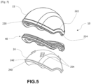
- the light source 16 comprises in this example, as illustrated in the [ Fig.4 ], a plurality of light emitting diodes 162.
- the light emitting diodes 162 emit red light preferably with a wavelength around 630 nanometers, in a range of 620 to 640 nanometers. Alternatively, other wavelengths of light may be selected depending on the nature of the desired phototherapy treatment.
- the light emitting diodes 162 are carried by an electrical interconnection support 164.
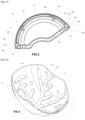
- the body 20 of the helmet 10 comprises outer 22 and inner 24 shell walls each extending from a crown portion proximal to a distal edge 220, 240 of the shell wall 22, 24.
- the two shell walls 22, 24, once assembled, define a peripheral edge 200 of the helmet 10 which delimits the opening for passage of the head of a user.
- the inner shell wall 24 is preferably made of a material that allows the light flux emitted by the light source 16 to pass through.
- the material is translucent to allow uniform diffusion of the light as well as natural protection of the user against glare.
- translucent we mean a material that allows light to pass through but is not necessarily transparent.
- the choice of a translucent material rather than a transparent material also makes it possible, at the aesthetic level, to make the diodes of the light source less visible.
- the material can be chosen to be transparent to the light rays emitted by the light sources.
- the inner shell wall 24 can also be referred to as an inner window because of its light transmission properties.
- the inner wall 24 is made of a thermoformable plastic material, for example a mixture of polystyrene and polyethylene (acronym PS-PE).
- the light source 16 is arranged between the two shell walls 22, 24 and emits towards the inside of the helmet 10.
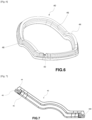
- the helmet 10 also comprises a circumferential headband 40 for adjusting the helmet 10 to the user's head circumference, attached to the peripheral edge 200.
- This headband 40 makes it possible to adjust the cavity 12 of the helmet 10 to the user's head circumference, this head circumference exhibiting great variability within the general population.
- this headband 40 comprises a body provided with a deformation portion 46 extending radially towards the inside of the helmet 10 which is configured to deform between a rest position deployed radially towards the inside of the helmet 10 and a compressed position between the helmet 10 and the user's head in the use configuration.
- this deformation portion 46 is hollow which makes it possible, for example, to guide the deformation along a preferential deformation line.
- the headband 40 is held attached to the helmet after assembly of the two shell walls 22, 24 together.
- the headband 40 comprises in the example described two attachment portions, a first attachment portion 48 outside the helmet 10 and a second attachment portion 44 inside the helmet 10.
- the deformation portion 46 extends towards the inside of the helmet 10 by a peripheral attachment bead 44 which forms the second attachment part.
- This bead 44 is preferably pinched between reliefs of the distal edges 220, 240 of hull walls 22 and 24.
- the deformation portion 46 extends towards the outside of the helmet 10 by a peripheral external anchoring heel 48 forming the first attachment part of the headband 40.
- This heel 48 is preferably retained by embedding in a relief provided on a rear face of the external shell wall 22, for example in the distal edge 220.
- the first attachment portion 48 is housed in a circumferential groove 224 formed on the external face of the outer helmet wall 22.
- the strip 40 comprises a free edge 480 curved in a U shape ([ Fig.7 ]) which fits radially into the circumferential groove 224 formed on the outer face of the shell wall 22.
- the inner shell wall 24 comprises on its rear face a circumferentially projecting rib 242 which forms a support shoulder 244 at the distal edge 240 such that the bead 44 of the strip 40 is gripped inside this shoulder 244 by the inner shell wall 24 against a relief of the outer shell wall 22.
- the distal edge 220 of the outer wall 22 is folded at the end projecting inwards to form a rim 226 extending radially inwards, forming a support shoulder 228 such that the bead 44 is gripped inside this shoulder 228 by the outer shell wall 22 against a relief of the inner shell wall 24.
- the deformation portion 46 may have a solid or hollow cross-section and of varied shape, for example of a shape chosen from the following list: polygonal, square, rectangular, triangular, circular, non-circular, oblong, oval, elliptical, crenellated, star-shaped, etc.
- the strip 40 is made of a deformable and resilient material with a shore A hardness of between 25 and 95 shore, preferably 50 shore.
- the strip 40 is made of a material comprising a polyurethane or silicone elastomer. Furthermore, preferably, the strip 40 has a passage 42 for an electrical power supply cable of the source 16. For example, the attachment portion 44 is locally interrupted to form the passage 42.
- the helmet 10 also comprises, in the illustrated example, on its peripheral edge 200, two notches corresponding to the ear contour areas.
- the headband 40 has a general arch shape having a curvilinear circumferential profile with preferably two ear contour notches. This makes it possible to clear the user's ears in the usage configuration.
- the outer shell 22 is provided on its inner face with an end which flares outwards to form a collar 222 before curving towards the interior by its edge 226,
- the helmet 10 further comprises a heat dissipation layer 26 interposed between the two shell walls 22, 24.
- the layer 26 is shaped into a plate configured to extend into the body of the helmet 10.
- the plate 26 forms a support for the light source.
- the light source 16 comprises a flexible support 164 and a plurality of light-emitting diodes 162.
- the flexible support 164 has, for example, a star-shaped configuration in order to conform to the concavity of the shell walls 22, 24.
- the support 164 is attached to an internal face of the heat dissipation plate 26 which is oriented towards the cavity 12 of the helmet 10.
- the heat dissipation plate 26 is made of a light-opaque material so that light cannot pass through the helmet 10 in an area covered by the heat dissipation layer 26.
- the plate is an aluminum plate.
- the headband 40, the outer shell wall 22 being made of translucent materials, the outer shell wall 22 has on its distal edge 220 a locally thickened pattern which locally prevents light from passing so as to produce a light pattern.
- the headband 40 is arranged on the helmet 10 such that the headband 40 cannot be removed without dismantling the two shell walls 22, 24 from each other.
- the two shell walls 22, 24 are assembled with each other by permanent (irreversible) or liberal (reversible) connecting means 250.
- the connecting means comprise a plurality of fastening elements 250, for example spaced apart from each other.
- These fastening elements 250 have complementary geometric profiles that can be mechanically assembled to each other, reversibly or irreversibly.
- irreversible assembly is meant an assembly that is inviolable by its physical and mechanical strength or by its chemical inertia (in the case of gluing for example).
- the assembly of the two shell walls 22, 24 together is irreversible.
- This is an assembly, for example, by reciprocal interlocking by clipping or by snap-fastening arranged in such a way that it is not possible to separate the two walls 22, 24 without damaging the connecting means 250 in rupture zones. This prevents a user from unintentionally dismantling the helmet 10. This makes it possible to ensure that the headband 40 cannot be removed from the helmet 10 without irreversible damage to the body of the helmet 10.
- the connecting means 250 comprise projections 254 provided on one 24 of the walls which penetrate into corresponding recesses of the other 22 of the walls.
- the projections 254 are in the form of clips.
- the recesses have complementary teeth (not illustrated) intended to cooperate with the projections 254 of the wall 24.
- the two walls 22, 24 are coupled together by the clips 254, for example made of plastic material and comprising for example orifices 252 coinciding with the two walls 22, 24 allowing the insertion of an element for fixing the walls 22, 24 together.
- a fixing element (not shown) makes it possible to constrain the inner window 24 formed by the inner shell wall 24 against the outer shell wall 22, for example by screwing.
- the fixing elements are chosen, for example, from: screws, bolts, a crimping, a rivet, a seal.
- the helmet 10 is in several separate parts, an outer shell wall 22, an inner shell wall 24, a heat dissipation plate 26, a light source 16, an adjustment headband 40.
- the adjustment headband 40 can be selected for example from a group of three headbands corresponding to three different head circumferences corresponding to three different dimensional categories: a small dimension, a medium dimension and a large dimension. It is therefore only at the time of assembly of the headband 40 to the body of the helmet 10 that the dimensional category of the helmet 10 is defined.
- the assembly order is as follows: the heat dissipation plate 26 and the light source 16 are positioned inside the concavity of the outer shell wall 22.
- the strip 40 is prepositioned by being connected to the outer shell wall 22 by means of the anchor heel 48 which is inserted into the peripheral groove 224 and the remainder of the strip 40 comes to be positioned naturally in its final destination position by elasticity and shape memory.
- the window formed by the inner shell wall 24 is then assembled on the outer shell wall 22 so that when the window 24 is screwed onto the outer shell wall 22, the strip 40 is constrained by its bead 44 between the reliefs of the two shell walls 22, 24 and immobilized in its final position.
Landscapes
- Health & Medical Sciences (AREA)
- Biomedical Technology (AREA)
- Life Sciences & Earth Sciences (AREA)
- Engineering & Computer Science (AREA)
- Nuclear Medicine, Radiotherapy & Molecular Imaging (AREA)
- Pathology (AREA)
- Biophysics (AREA)
- Radiology & Medical Imaging (AREA)
- Animal Behavior & Ethology (AREA)
- General Health & Medical Sciences (AREA)
- Public Health (AREA)
- Veterinary Medicine (AREA)
- Radiation-Therapy Devices (AREA)
- Helmets And Other Head Coverings (AREA)
Applications Claiming Priority (1)
| Application Number | Priority Date | Filing Date | Title |
|---|---|---|---|
| FR2305751A FR3149512B1 (fr) | 2023-06-07 | 2023-06-07 | Dispositif de traitement par photothérapie. |
Publications (1)
| Publication Number | Publication Date |
|---|---|
| EP4474004A1 true EP4474004A1 (de) | 2024-12-11 |
Family
ID=87974635
Family Applications (1)
| Application Number | Title | Priority Date | Filing Date |
|---|---|---|---|
| EP24180045.7A Pending EP4474004A1 (de) | 2023-06-07 | 2024-06-04 | Vorrichtung zur behandlung durch phototherapie |
Country Status (2)
| Country | Link |
|---|---|
| EP (1) | EP4474004A1 (de) |
| FR (1) | FR3149512B1 (de) |
Citations (6)
| Publication number | Priority date | Publication date | Assignee | Title |
|---|---|---|---|---|
| EP2477697A2 (de) | 2009-09-18 | 2012-07-25 | Apira Science, Inc. | Lichttherapievorrichtung für behandlungen der haare und der kopfhaut |
| US20200353283A1 (en) * | 2015-07-28 | 2020-11-12 | Know Bio, Llc | Phototherapy devices for treatment of dermatological disorders of the scalp |
| CN213030089U (zh) * | 2020-06-02 | 2021-04-23 | 阎彩虹 | 穿戴式洗头设备 |
| CN214050217U (zh) * | 2020-04-28 | 2021-08-27 | 深圳半岛医疗有限公司 | 生发帽 |
| EP4091667A1 (de) * | 2021-05-17 | 2022-11-23 | Farmasuisse Servizi S.r.l. | Helm zur behandlung der kopfhaut und haare mit photobiostimulationstechnologie |
| CN115670099A (zh) * | 2021-07-23 | 2023-02-03 | 北京夏禾科技有限公司 | 一种多功能额部佩戴品 |
Family Cites Families (1)
| Publication number | Priority date | Publication date | Assignee | Title |
|---|---|---|---|---|
| US20220370823A1 (en) * | 2021-05-24 | 2022-11-24 | Sander Electronic Co., Ltd. | Light based therapy helmet |
-
2023
- 2023-06-07 FR FR2305751A patent/FR3149512B1/fr active Active
-
2024
- 2024-06-04 EP EP24180045.7A patent/EP4474004A1/de active Pending
Patent Citations (6)
| Publication number | Priority date | Publication date | Assignee | Title |
|---|---|---|---|---|
| EP2477697A2 (de) | 2009-09-18 | 2012-07-25 | Apira Science, Inc. | Lichttherapievorrichtung für behandlungen der haare und der kopfhaut |
| US20200353283A1 (en) * | 2015-07-28 | 2020-11-12 | Know Bio, Llc | Phototherapy devices for treatment of dermatological disorders of the scalp |
| CN214050217U (zh) * | 2020-04-28 | 2021-08-27 | 深圳半岛医疗有限公司 | 生发帽 |
| CN213030089U (zh) * | 2020-06-02 | 2021-04-23 | 阎彩虹 | 穿戴式洗头设备 |
| EP4091667A1 (de) * | 2021-05-17 | 2022-11-23 | Farmasuisse Servizi S.r.l. | Helm zur behandlung der kopfhaut und haare mit photobiostimulationstechnologie |
| CN115670099A (zh) * | 2021-07-23 | 2023-02-03 | 北京夏禾科技有限公司 | 一种多功能额部佩戴品 |
Also Published As
| Publication number | Publication date |
|---|---|
| FR3149512B1 (fr) | 2025-05-30 |
| FR3149512A1 (fr) | 2024-12-13 |
Similar Documents
| Publication | Publication Date | Title |
|---|---|---|
| FR2757371A1 (fr) | Dispositif elastique a grande capacite d'allongement pour l'extension de tissu vivant | |
| CA2382325A1 (fr) | Emballage pour la presentation groupee d'au moins deux articles | |
| FR2690840A1 (fr) | Dispositif d'extension de tissu vivant. | |
| EP3125999A1 (de) | Behandlungsvorrichtung mit einem lichtleiter | |
| FR2896133A1 (fr) | Doublure de casque | |
| USD949471S1 (en) | Cosmetics applicator | |
| EP4182016B1 (de) | Freihändige lichttherapievorrichtung | |
| EP4474004A1 (de) | Vorrichtung zur behandlung durch phototherapie | |
| FR3037779A1 (fr) | Article pour decorer la peau ou un ongle d'un humain et procede mettant en œuvre un tel article | |
| EP4474006A1 (de) | Vorrichtung zur behandlung durch phototherapie | |
| FR2797564A1 (fr) | Casquette a taille variable comportant une bande de reglage | |
| FR2512651A1 (fr) | Produits anti-rides | |
| EP4474005A1 (de) | Vorrichtung zur behandlung durch phototherapie | |
| FR2905239A1 (fr) | Dispositif pour isoler au moins une meche de cheveux | |
| EP1566114A1 (de) | Vorrichtung zum Auftragen eines Haarpflegeproduktes auf Haarsträhnen | |
| FR3123221A1 (fr) | Dispositif de traitement de photothérapie | |
| EP4347012A1 (de) | Vorrichtung zur phototherapiebehandlung | |
| USD1014387S1 (en) | Wheel for automobile | |
| FR2744623A1 (fr) | Dispositif elastique d'extension de tissu vivant | |
| FR3149511A1 (fr) | Dispositif de traitement par photothérapie. | |
| FR3143374A1 (fr) | Dispositif cosmétique portatif. | |
| KR200297353Y1 (ko) | 모자의 밴드띠 흡착 구조 | |
| WO2022248792A1 (fr) | Dispositif de traitement de photothérapie | |
| FR3020575A1 (fr) | Equipement de traitement par phototherapie avec dispositif de protection | |
| FR2921802A1 (fr) | Ensemble de decoration pour casque |
Legal Events
| Date | Code | Title | Description |
|---|---|---|---|
| PUAI | Public reference made under article 153(3) epc to a published international application that has entered the european phase |
Free format text: ORIGINAL CODE: 0009012 |
|
| STAA | Information on the status of an ep patent application or granted ep patent |
Free format text: STATUS: THE APPLICATION HAS BEEN PUBLISHED |
|
| AK | Designated contracting states |
Kind code of ref document: A1 Designated state(s): AL AT BE BG CH CY CZ DE DK EE ES FI FR GB GR HR HU IE IS IT LI LT LU LV MC ME MK MT NL NO PL PT RO RS SE SI SK SM TR |
|
| STAA | Information on the status of an ep patent application or granted ep patent |
Free format text: STATUS: REQUEST FOR EXAMINATION WAS MADE |
|
| 17P | Request for examination filed |
Effective date: 20250511 |
|
| GRAP | Despatch of communication of intention to grant a patent |
Free format text: ORIGINAL CODE: EPIDOSNIGR1 |
|
| STAA | Information on the status of an ep patent application or granted ep patent |
Free format text: STATUS: GRANT OF PATENT IS INTENDED |
|
| RIC1 | Information provided on ipc code assigned before grant |
Ipc: A61N 5/06 20060101AFI20250926BHEP |
|
| INTG | Intention to grant announced |
Effective date: 20251015 |
|
| RAP3 | Party data changed (applicant data changed or rights of an application transferred) |
Owner name: LUCIBEL SA |
|
| RAP3 | Party data changed (applicant data changed or rights of an application transferred) |
Owner name: LUCIBEL SA |