EP4182016B1 - Freihändige lichttherapievorrichtung - Google Patents
Freihändige lichttherapievorrichtung Download PDFInfo
- Publication number
- EP4182016B1 EP4182016B1 EP21755526.7A EP21755526A EP4182016B1 EP 4182016 B1 EP4182016 B1 EP 4182016B1 EP 21755526 A EP21755526 A EP 21755526A EP 4182016 B1 EP4182016 B1 EP 4182016B1
- Authority
- EP
- European Patent Office
- Prior art keywords
- headband
- snap
- ear
- shell
- ear units
- Prior art date
- Legal status (The legal status is an assumption and is not a legal conclusion. Google has not performed a legal analysis and makes no representation as to the accuracy of the status listed.)
- Active
Links
Images


Classifications
-
- A—HUMAN NECESSITIES
- A61—MEDICAL OR VETERINARY SCIENCE; HYGIENE
- A61N—ELECTROTHERAPY; MAGNETOTHERAPY; RADIATION THERAPY; ULTRASOUND THERAPY
- A61N5/00—Radiation therapy
- A61N5/06—Radiation therapy using light
- A61N5/0613—Apparatus adapted for a specific treatment
- A61N5/0616—Skin treatment other than tanning
- A61N5/0617—Hair treatment
-
- A—HUMAN NECESSITIES
- A61—MEDICAL OR VETERINARY SCIENCE; HYGIENE
- A61N—ELECTROTHERAPY; MAGNETOTHERAPY; RADIATION THERAPY; ULTRASOUND THERAPY
- A61N5/00—Radiation therapy
- A61N5/06—Radiation therapy using light
- A61N5/0613—Apparatus adapted for a specific treatment
- A61N5/062—Photodynamic therapy, i.e. excitation of an agent
-
- A—HUMAN NECESSITIES
- A61—MEDICAL OR VETERINARY SCIENCE; HYGIENE
- A61N—ELECTROTHERAPY; MAGNETOTHERAPY; RADIATION THERAPY; ULTRASOUND THERAPY
- A61N5/00—Radiation therapy
- A61N5/06—Radiation therapy using light
- A61N2005/0626—Monitoring, verifying, controlling systems and methods
- A61N2005/0629—Sequential activation of light sources
-
- A—HUMAN NECESSITIES
- A61—MEDICAL OR VETERINARY SCIENCE; HYGIENE
- A61N—ELECTROTHERAPY; MAGNETOTHERAPY; RADIATION THERAPY; ULTRASOUND THERAPY
- A61N5/00—Radiation therapy
- A61N5/06—Radiation therapy using light
- A61N2005/0632—Constructional aspects of the apparatus
- A61N2005/0633—Arrangements for lifting or hinging the frame which supports the light sources
-
- A—HUMAN NECESSITIES
- A61—MEDICAL OR VETERINARY SCIENCE; HYGIENE
- A61N—ELECTROTHERAPY; MAGNETOTHERAPY; RADIATION THERAPY; ULTRASOUND THERAPY
- A61N5/00—Radiation therapy
- A61N5/06—Radiation therapy using light
- A61N2005/0635—Radiation therapy using light characterised by the body area to be irradiated
- A61N2005/0643—Applicators, probes irradiating specific body areas in close proximity
- A61N2005/0645—Applicators worn by the patient
- A61N2005/0647—Applicators worn by the patient the applicator adapted to be worn on the head
-
- A—HUMAN NECESSITIES
- A61—MEDICAL OR VETERINARY SCIENCE; HYGIENE
- A61N—ELECTROTHERAPY; MAGNETOTHERAPY; RADIATION THERAPY; ULTRASOUND THERAPY
- A61N5/00—Radiation therapy
- A61N5/06—Radiation therapy using light
- A61N2005/0658—Radiation therapy using light characterised by the wavelength of light used
- A61N2005/0662—Visible light
Definitions
- the present invention relates to a phototherapy treatment device for an external region of the body of a living being. More particularly but not exclusively, it applies to the phototherapy treatment of the head surface of a user, for example to the treatment of the scalp as a treatment for baldness.
- the treatment consists of applying light radiation with a predefined emission spectrum directly to the scalp.
- This phototherapy treatment can also be applied in combination with a photosensitizing product applied to the area to be treated a few hours before exposure to the light radiation to increase the effectiveness of the treatment.
- photodynamic therapy also known by the English acronym PDT "Photo Dynamic Therapy”
- the radiation is preferably substantially monochromatic or has an emission spectrum within a relatively narrow band of wavelengths.
- the emission spectrum has a peak wavelength in the red visible light or blue visible light, these wavelengths having demonstrated particular effectiveness in treating certain skin conditions.
- phototherapy treatment in a predefined wavelength range can have a beneficial effect on many skin problems, such as scars, stretch marks, acne, wrinkles and fine lines.
- the cells in the irradiated region will react according to a principle similar to that of photosynthesis in plants.
- the light will stimulate the cells, and more specifically certain cellular structures of the cell, such as the mitochondria.
- ATP acronym for Adenosine Tri Phosphate
- red light for example at the wavelength of 630 nm, allows stimulation of hair regrowth, improvement of hair quality and density as well as stabilization of hair loss.
- WO 2004/026400 A1 discloses a hands-free portable phototherapy device, of the type comprising a main head unit having a headband-shaped band configured to be positioned above a user's head, wherein attachment of the headband to the ear units allows relative rotation of the headband with respect to the ear units.
- the invention aims in particular to remedy these drawbacks by proposing an ergonomic, aesthetic and easily transportable phototherapy device.
- the invention relates to a hands-free portable phototherapy device, of the type comprising a main head unit comprising a headband in the form of a hoop configured to be positioned above the head of a user extending between first and second end portions and comprising a light source emitting on an internal portion of the headband and first and second ear units configured to be worn on the ears of a user, the end portions and of the headband are connected respectively to the first and second ear units such that in the mounted configuration the headband exerts compression of the ear units against the head of the user to ensure that the device is held hands-free, in which the end portions each carry releasable attachment means of the headband configured to cooperate respectively with complementary attachment means carried by the ear units of the snap-on type, an end portion of the headband comprising a flexible tab provided with a loop, and in which the attachment means are configured to allow, in the position snap-on, a relative rotation of the headband relative to the ear units.
- the device allows treatment of the entire surface of the head without being more cumbersome, for example, than a conventional audio headset.
- the headband since the headband only covers a portion of the user's head, it is possible to successively cover the occipital, parietal and frontal areas of the scalp by a simple relative rotation of the headband with respect to the ear units.
- the phototherapy light headband is connected by snap-fastening, it can be exchanged for any accessory provided with identical attachment means.
- a device according to the invention may further comprise one or more of the following features.
- the ear unit comprises an outer shell defining dorsal and ventral walls and a peripheral annular wall, the shell defining a receiving slot on its peripheral annular wall for the introduction of one of the end portions of the headband into a snap-in groove provided of a snap-fit shape configured to retain said end portion.
- the snap-in shape and the end portion are shaped to cooperate in rotation with respect to each other in a snap-in position.
- the shell comprises a recessed portion inner and an internal flexible skirt housed inside the recessed portion delimiting the snap-in groove, the skirt having an external protrusion projecting out of the shell through an opening formed in the dorsal wall of the shell, the protrusion forming a push button configured so that manual pressure on the button causes flexion of the skirt suitable for ensuring disengagement of the end portion and the snap-in shape allowing the release of the end portion.
- the skirt has a dorsal wall carrying the protuberance and a ventral wall carrying the snap-fit shape and two lateral partitions flexurally connecting the ventral and dorsal walls together.
- the side partitions are configured to limit the angular movement of the end portion.
- the snap-in shape has the shape of a substantially rounded bump.
- the snap-in shape is provided with a notched or ridged surface to generate a tactile indication when rotating the headband relative to the ear units.
- an end portion of the headband comprises a flexible tab provided with a loop.
- the headband comprises a housing provided with a connector port arranged through an opening in the housing to provide a snap-on magnetically coupled interface with a complementary connector socket for powering the light source.
- the ear unit comprises a speaker unit adapted to output an audio signal.
- the device comprises control means, such as a microcontroller with a program loaded in memory, of the light source according to a plurality of ignition sequences.
- control means such as a microcontroller with a program loaded in memory, of the light source according to a plurality of ignition sequences.
- Assembly comprising a device according to the invention and further comprising at least one other head unit, characterized in that the other head unit comprises releasable attachment means identical to the releasable attachment means of the headband so as to allow the attachment of this other head unit directly onto the ear units.
- the other head unit carries means configured to perform at least in part a function chosen from a lighting function, a decorative function, a facial phototherapy treatment function, a video image acquisition function
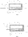
- FIG. 1 It has been schematically represented on the Figure 1 an assembly 100 comprising a phototherapy device 10 according to the invention and means 200 for electrically connecting the device 10 to an external electrical power source (not shown), such as for example the mains power supply.
- an external electrical power source not shown
- the hands-free portable phototherapy treatment device 10 comprises a main head unit 12 comprising a headband 14 in the form of a hoop equipped with a light source 16 and configured to be positioned above the head of a user.
- the light source 16 preferably comprises a plurality of light-emitting diodes emitting in red light, for example within a wavelength range between 600 nm and 700 nm, and preferably at the wavelength 630 nm.
- the strip 14 comprises a housing 18 shaped like an arch.
- the housing 18 comprises two internal 20 and external 22 parts defined relative to the general curvature of the strip 14.
- These internal 20 and external 22 parts delimit between them a housing, for example for the light source 16 and a printed circuit board forming a support for this source 16.
- a printed circuit board can be made of a flexible material to match the arcuate shape of the internal housing of the housing 18.
- the internal part 20 comprises an emission window 22 for the light emitted by the light source 16 made of a diffusing material, for example a plastic material such as polycarbonate.
- the housing 18 is, in this example, provided with a connector port 23 arranged through an opening in the housing 18 to provide, for example, an electrical power supply interface with the connection means 200.
- this interface may be of the snap-on magnetic coupling type with a complementary connector socket for the electrical power supply of the light source 14.
- the electrical connection means 200 make it possible to electrically recharge an internal battery unit housed in the housing 18 of the device 10.
- an opening is made on a peripheral edge of the housing 18 and, in this embodiment and as illustrated in the figures, the connector port 23 makes it possible to form a connectable interface accessible from the outside of the housing 18 for the connection of a connector socket 208 of the connection means 200, complementary to the connector port 23.
- this connectable interface is of the magnetic coupling and snap-fastening type.
- the connecting means 200 comprise a separable connector socket 204 for connection to the mains power supply, for example.
- the socket 204 and the port 23 may have rotational symmetry such that a 180-degree rotation of either the socket or the port, clockwise or counterclockwise, results in an identical electrical connection, thus eliminating the need to check alignment when establishing a connection.
- the socket 204 and the port 23 may only be connected in a single position.
- the magnetized elements of the magnetically coupled interface are polarized in such a way that the user can only connect the interface in a single position.
- the interface is thus provided with a keying device so that if the relative direction of the socket 204 and the port 23 is reversed, the magnetized elements repel each other.
- the connector socket 204 is also connected to a first end of an electrical power supply cable 202, this cable 202 being provided at its other end with a connector 206 of the “USB” type or equivalent.
- This connector 206 is preferably capable of being engaged in a standard format male socket 208 for electrical connection to a domestic electrical power supply network.
- the housing 18 also comprises an on/off button 24 and an operating indicator light 26 and houses, for example, other electronic components not described.
- the device 10 comprises first 30A and second 30B ear units configured to be worn on the user's ears.
- the headband 14 comprises two end portions 14A, 14B attached respectively to the first 30A and second 30B ear units such that in the mounted configuration the headband 14 exerts compression of the ear units 30A, 30B against the user's head to ensure that the hands-free device 10 is held on the user's head.
- the headband 14 is elastically deformable to adapt to the shape of the user's head by elastic return.
- the ends 14A, 14B each carry releasable attachment means of the snap-on type of the headband 14 configured to cooperate respectively with complementary attachment means 31A, 31B carried respectively by the ear units 30A, 30B.
- the attachment means 14A, 14B, 31A, 31B are configured to allow, in the snap-on position, a relative rotation of the headband 14 relative to the ear units 30A, 30B towards the ears of the user.
- the ear unit 30A or 30B comprises an outer shell 32 defining dorsal 34 and ventral 36 walls and a peripheral annular wall 38.
- the shell 32 defines a receiving slot 40 on its peripheral annular wall for the introduction of the end portion 14A of the headband 14.
- the device 10 comprises two identical ear units 30A, 30B mounted symmetrically on either side of the headband 14.
- FIGS. 3 and 4 illustrate the mechanism of the snap-fastening means according to a preferred embodiment of the invention.
- these fastening means may have other configurations without departing from the scope of the invention defined by the claims.
- the shell 32 of the ear unit 30A provided with its snap-in slot 40 formed on its peripheral annular wall 38 allowing the introduction of the loop of the end part 14A of the headband 14.
- the loop of the end part 14A is inserted inside a snap-in groove 44 formed inside the shell 32.
- the snap groove 44 is provided with a snap shape 46 configured to retain the end portion 14A of the headband 14 while allowing relative rotation of the headband 14 relative to the ear units 30A, 30B in the configuration mounted on the user's ears.
- the shell 32 of the ear unit 30A includes an inner recessed portion 48 or internal bore 48 and an inner flexible skirt 50 housed within the inner bore 48 defining the snap groove 44.
- the skirt 50 has an outer protrusion 52 projecting out of the shell 32 through an opening formed in the back wall 34 of the shell 32.
- the protrusion 52 forms a push button configured so that manual pressure on the button causes flexion of the skirt 50 suitable for ensuring disengagement of the end portion 14A and the snap shape 46 allowing the release of the previously engaged end portion 14A.
- the skirt 50 has a dorsal wall 54 carrying on an external face the protuberance 52 and a ventral wall 56 carrying on an internal face the snap-fastening shape 46 and two lateral partitions (not visible in the figures) connecting in flexion the ventral 54 and dorsal 56 walls, together.
- the dorsal wall 54 moves and the ventral wall 56 is also driven in flexion by the two lateral partitions connected to the dorsal wall 54.
- other forms of engagement and release of the snap-fastening can be envisaged without departing from the scope of the invention.
- the shell 32 also comprises a cylindrical bore or cylindrical housing for retaining an elastic element 60, for example a spring operating in compression. Furthermore, optionally, the shell 32 further comprises an ejection key 62 mechanically connected to the elastic element 60.
- the key 62 in the rest position, the key 62 is driven, by the deployed spring 60, into the snap groove 44 while the introduction of the loop of the end part 14A causes the ejection key 62 to be pushed back until the snap shape 46 is placed inside the loop of the end part 14A.
- an end portion 14A, 14B of the headband 14 comprises a flexible tab provided with a loop.
- the snap-fit shape 46 has the shape of a substantially rounded bump and the end portion 14A comprises a loop. Furthermore, in the example described, the boss 46 is provided with a surface relief configured to form notches thus generating a tactile indication during rotation of notches. For example, boss 46 is striated or notched on its periphery.
- the lateral partitions of the skirt 50 are configured to limit the angular rotational movement of the end portion 14A inside the slot 40.
- the ear unit 30A may comprise a loudspeaker unit capable of emitting an audio signal.
- This loudspeaker unit is represented schematically by a rectangle referenced 300 on the Figures 3 and 4 but will not be further detailed.
- the assembly 100 further comprises at least one other head unit illustrated in the Figure 6 .
- This other head unit 70 comprises releasable attachment means identical to the releasable attachment means of the headband 14 so as to allow the attachment of this other head unit 70 directly onto the ear units 30A, 30B.
- the other head unit 70 carries means configured to perform at least in part a function chosen from a lighting function, a decorative function, a facial phototherapy treatment function, a video image acquisition function, for example a sports camera of the GOPRO ® type.
- the other head unit 70 comprises a light function performed for example by a light source 72 of white light.
- the user wishes to treat the scalp. He selects the head unit 12 for phototherapy treatment. He hooks the end portions 14A, 14B to the ear units 30A, 30B. Then, he positions the device 10 above his head such that the headband 14 extends above the area of the scalp to be treated and the ear units 30A, 30B around the ears. During this step, the user slightly separates the ear units 30A, 30B from each other by elastic deformation of the headband 14 and then releases the headband 14, the latter coming by elastic return to compress the ear units 30A, 30B against the user's ears.
- the user starts the phototherapy program by pressing the on/off button 26.
- the indicator light 24 then indicates by a light that the phototherapy program is activated.
- the light source 16 illuminates the scalp for a predefined treatment duration that can be programmed.
Landscapes
- Health & Medical Sciences (AREA)
- Biomedical Technology (AREA)
- Life Sciences & Earth Sciences (AREA)
- Engineering & Computer Science (AREA)
- Nuclear Medicine, Radiotherapy & Molecular Imaging (AREA)
- Pathology (AREA)
- Biophysics (AREA)
- Radiology & Medical Imaging (AREA)
- Animal Behavior & Ethology (AREA)
- General Health & Medical Sciences (AREA)
- Public Health (AREA)
- Veterinary Medicine (AREA)
- Radiation-Therapy Devices (AREA)
Claims (13)
- Tragbare, freihändige Phototherapievorrichtung (10) des Typs, der eine Hauptkopfeinheit (12) mit einem Stirnband umfasst. (14) in Form eines Bügels, der so konfiguriert ist, dass er über dem Kopf eines Benutzers positioniert werden kann, der sich zwischen einem ersten (14A) und einem zweiten (14B) Endabschnitt erstreckt und eine Lichtquelle (16), die auf einen inneren Abschnitt (20) des Stirnbands (14) strahlt, und eine erste (30A) und eine zweite (30B) Ohreinheit umfasst, die so konfiguriert sind, dass sie an den Ohren eines Benutzers getragen werden können, die Endabschnitte (14A) und (14B) des Kopfbands (14) jeweils mit der ersten (30A) und der zweiten (30B) Ohreinheit verbunden sind, so dass das Kopfband (14) in der montierten Konfiguration eine Kompression der Ohreinheiten (30A, 30B) gegen den Kopf des Benutzers ausübt, um das freihändige Halten der Vorrichtung (10) zu gewährleisten, wobei die Endabschnitte (14A, 14B) jeweils lösbare Einhakmittel des Kopfbandes (14) tragen, die so konfiguriert sind, dass sie jeweils mit komplementären Einhakmitteln (31A, 31B) zusammenwirken, wobei die komplementären Einhakmittel (31A, 31B) jeweils mit den Endabschnitten 14A, 14B) des Kopfbandes (14) zusammenwirken, 31B), die von den Ohreinheiten (30A, 30B) vom Einschnapptyp getragen werden, wobei ein Endabschnitt (14A, 14B) des Kopfbandes (14) eine flexible Lasche umfasst, die mit einer Schnalle versehen ist, und wobei die Einhakmittel (14A, 31A ; 14B, 31B) so konfiguriert sind, dass sie in der Einrastposition eine relative Drehung des Kopfbands (14) in Bezug auf die Ohreneinheiten (30A, 30B) zulassen.
- Vorrichtung (10) nach dem vorhergehenden Anspruch, wobei die Ohreinheit (30A, 30B) eine äußere Schale (32), die eine Rückenwand (34) und eine Bauchwand (36) begrenzt, und eine ringförmige Umfangswand (38) umfasst, die Schale (32) an ihrer ringförmigen Umfangswand (38) einen Aufnahmeschlitz (40) zum Einführen eines der Endabschnitte (14A, 14B) des Kopfbandes (14) in eine Rastnut (44) begrenzt, die mit einer Rastform (46) versehen ist, die so konfiguriert ist, dass sie den Endabschnitt (14A, 14B) festhält.
- Vorrichtung (10) nach dem vorhergehenden Anspruch, wobei die Einrastform (46) und der Endabschnitt (14A, 14B) so geformt sind, dass sie in einer Einrastposition drehbar relativ zueinander zusammenwirken.
- Vorrichtung (10) nach dem vorhergehenden Anspruch, wobei die Schale (32) einen inneren ausgesparten Abschnitt (48) und eine innere flexible Schürze (50) aufweist, die in dem ausgesparten Abschnitt (48) untergebracht ist, der die Rastnut (44) begrenzt, wobei die Schürze (50) einen äußeren Vorsprung (52) aufweist, der aus der Schale (32) durch eine äußere Ausbuchtung (52) vorsteht, die durch die Rastnut (44) hindurch verläuft. Öffnung, die in der Rückenwand (34) des Rumpfes (32) ausgebildet ist, wobei der Vorsprung (52) einen Druckknopf bildet, der so konfiguriert ist, dass ein manueller Druck auf den Knopf (52) eine Biegung der Schürze bewirkt. (50), die geeignet ist, das Lösen des Endabschnitts (14A, 14B) zu gewährleisten, und der Einrastform (46), die die Freigabe des Endabschnitts (14A, 14B) ermöglicht.
- Vorrichtung (10) nach dem vorhergehenden Anspruch, wobei die Schürze (50) eine Rückenwand 54), die den Vorsprung (52) trägt, und eine Bauchwand (56), die die Rastform (46) trägt, sowie zwei Seitenwände aufweist, die die Bauchwand (52) und die Rückenwand biegsam miteinander verbinden (54) untereinander.
- Vorrichtung (10) nach dem vorhergehenden Anspruch, wobei die Seitenwände so gestaltet sind, dass sie die Winkelauslenkung des Endabschnitts (14A, 14B) begrenzen.
- Vorrichtung (10) nach einem der Ansprüche 2 bis 6, wobei die Einrastform (46) die Form eines im Wesentlichen abgerundeten Höckers hat.
- Vorrichtung (10) nach dem vorhergehenden Anspruch, wobei die Einrastform (46) mit einer gezahnten oder geriffelten Oberfläche versehen ist, um eine taktile Anzeige zu erzeugen, wenn das Kopfband (14) in Bezug auf die Ohreneinheiten (30A, 30B) gedreht wird.
- Vorrichtung (10) nach einem der vorhergehenden Ansprüche, wobei das Stirnband (14) ein Gehäuse (18) umfasst, das mit einem Steckeranschluss (23) versehen ist, der durch eine Öffnung des Gehäuses (18) hindurch angeordnet ist, um eine magnetisch gekoppelte Schnittstelle zu bilden, die mit einem komplementären Steckeranschluss für die Stromversorgung der Lichtquelle (16) einschnappbar ist.
- Vorrichtung (10) nach einem der vorhergehenden Ansprüche, wobei die Ohreinheit (30A, 30B) eine Lautsprechereinheit umfasst, die zum Ausgeben eines Audiosignals geeignet ist.
- Vorrichtung (10) nach einem der vorhergehenden Ansprüche, die Mittel zur Steuerung, wie einen Mikrocontroller mit einem in den Speicher geladenen Programm, der Lichtquelle (16) gemäß einer Vielzahl von Zündsequenzen umfasst.
- Anordnung (100), die eine Vorrichtung (10) nach einem der vorhergehenden Ansprüche umfasst und außerdem mindestens eine weitere Kopfeinheit (70) umfasst, dadurch gekennzeichnet, dass die weitere Kopfeinheit (70) lösbare Hakenmittel umfasst, die identisch mit den lösbaren Hakenmitteln des Kopfbandes (14) sind, um so das Aufhängen dieser anderen Kopfeinheit direkt an den Ohreneinheiten (30A, 30B) ermöglichen.
- Anordnung (100) nach dem vorhergehenden Anspruch, bei der die andere Kopfeinheit (70) Mittel trägt, die so konfiguriert sind, dass sie zumindest teilweise eine Funktion ausführen, die aus einer Beleuchtungsfunktion, einer dekorativen Funktion, einer Funktion zur Phototherapiebehandlung des Gesichts und einer Funktion zur Erfassung von Videobildern ausgewählt ist.
Applications Claiming Priority (2)
| Application Number | Priority Date | Filing Date | Title |
|---|---|---|---|
| FR2007633A FR3112490B1 (fr) | 2020-07-20 | 2020-07-20 | Dispositif de photothérapie mains libres. |
| PCT/FR2021/051343 WO2022018369A1 (fr) | 2020-07-20 | 2021-07-17 | Dispositif de photothérapie mains libres |
Publications (3)
| Publication Number | Publication Date |
|---|---|
| EP4182016A1 EP4182016A1 (de) | 2023-05-24 |
| EP4182016C0 EP4182016C0 (de) | 2025-06-04 |
| EP4182016B1 true EP4182016B1 (de) | 2025-06-04 |
Family
ID=73013618
Family Applications (1)
| Application Number | Title | Priority Date | Filing Date |
|---|---|---|---|
| EP21755526.7A Active EP4182016B1 (de) | 2020-07-20 | 2021-07-17 | Freihändige lichttherapievorrichtung |
Country Status (3)
| Country | Link |
|---|---|
| EP (1) | EP4182016B1 (de) |
| FR (1) | FR3112490B1 (de) |
| WO (1) | WO2022018369A1 (de) |
Families Citing this family (2)
| Publication number | Priority date | Publication date | Assignee | Title |
|---|---|---|---|---|
| EP4385560A1 (de) * | 2022-12-14 | 2024-06-19 | Koninklijke Philips N.V. | Kopfhautbehandlungsvorrichtung |
| EP4470606A1 (de) * | 2023-05-30 | 2024-12-04 | Gbo Medizintechnik AG | Applikatoreinrichtung zum applizieren von magnetischen feldern zur magnetfeldtherapie |
Citations (1)
| Publication number | Priority date | Publication date | Assignee | Title |
|---|---|---|---|---|
| EP2477697B1 (de) * | 2009-09-18 | 2014-08-27 | Apira Science, Inc. | Lichttherapievorrichtung für behandlungen der haare und der kopfhaut |
Family Cites Families (7)
| Publication number | Priority date | Publication date | Assignee | Title |
|---|---|---|---|---|
| WO2004026400A1 (ja) * | 2002-09-20 | 2004-04-01 | Biotech Inc. | ヘッドフォン型育毛補助装置 |
| US8747446B2 (en) * | 2009-10-12 | 2014-06-10 | Chung-Yang Chen | Hair restoration caring device |
| US20140350643A1 (en) * | 2013-05-23 | 2014-11-27 | Apira Science, Inc. | Phototherapy apparatus for skin treatment |
| JP2016010482A (ja) * | 2014-06-27 | 2016-01-21 | パナソニックIpマネジメント株式会社 | 光育毛装置 |
| FR3024355A1 (fr) * | 2014-07-30 | 2016-02-05 | Jean Tien | Equipement pour l'application d'elements actifs sur le crane d'un patient |
| US20180021592A1 (en) * | 2016-05-18 | 2018-01-25 | Kim Segal | Hair growth stimulating band |
| US20190262628A1 (en) * | 2017-10-24 | 2019-08-29 | Laserstim, Inc. | Method of combining laser light therapy with bioactive compounds |
-
2020
- 2020-07-20 FR FR2007633A patent/FR3112490B1/fr active Active
-
2021
- 2021-07-17 WO PCT/FR2021/051343 patent/WO2022018369A1/fr not_active Ceased
- 2021-07-17 EP EP21755526.7A patent/EP4182016B1/de active Active
Patent Citations (1)
| Publication number | Priority date | Publication date | Assignee | Title |
|---|---|---|---|---|
| EP2477697B1 (de) * | 2009-09-18 | 2014-08-27 | Apira Science, Inc. | Lichttherapievorrichtung für behandlungen der haare und der kopfhaut |
Also Published As
| Publication number | Publication date |
|---|---|
| EP4182016C0 (de) | 2025-06-04 |
| FR3112490B1 (fr) | 2024-06-21 |
| WO2022018369A1 (fr) | 2022-01-27 |
| EP4182016A1 (de) | 2023-05-24 |
| FR3112490A1 (fr) | 2022-01-21 |
Similar Documents
| Publication | Publication Date | Title |
|---|---|---|
| EP4182016B1 (de) | Freihändige lichttherapievorrichtung | |
| EP2092842B1 (de) | Enthaarungsvorrichtung, die pulsierende elektromagnetische Strahlung benutzt | |
| WO1997025832A1 (fr) | Perfectionnement pour dispositif de communication du type electroacoustique destine a equiper un casque de protection | |
| US6095334A (en) | Mirror compact case | |
| FR3093438A1 (fr) | Dispositif de traitement de photothérapie. | |
| FR3123221A1 (fr) | Dispositif de traitement de photothérapie | |
| FR2905239A1 (fr) | Dispositif pour isoler au moins une meche de cheveux | |
| EP1871577A1 (de) | Rasierapparat | |
| WO1992018055A1 (fr) | Dispositif ecarteur de tissus pour interventions medicales et chirurgicales | |
| BE1011308A6 (fr) | Casquette transformable a combinaisons multiples fonctionnelles et esthetiques. | |
| EP4347012A1 (de) | Vorrichtung zur phototherapiebehandlung | |
| FR2700861A1 (fr) | Paire de lunettes modulable. | |
| FR3018692A1 (fr) | Module portatif de traitement par phototherapie. | |
| FR3143374A1 (fr) | Dispositif cosmétique portatif. | |
| FR2921800A1 (fr) | Ensemble de decoration pour casque | |
| FR2921802A1 (fr) | Ensemble de decoration pour casque | |
| CA2243290C (fr) | Perfectionnement pour dispositif de communication du type electroacoustique destine a equiper un casque de protection | |
| FR3110085A1 (fr) | Dispositif de traitement par photothérapie. | |
| EP4474006A1 (de) | Vorrichtung zur behandlung durch phototherapie | |
| CN214414335U (zh) | 一种美妆镜 | |
| EP2898790B1 (de) | Gerät zur Körperbehandlung mit integrierter Optik | |
| CH720476A1 (fr) | Fermoir pour bracelet | |
| EP4474003A1 (de) | Vorrichtung zur behandlung durch phototherapie | |
| FR3164630A1 (fr) | Dispositif pour exposer la peau d’un utilisateur à un rayonnement lumineux ou infrarouge | |
| FR3149510A1 (fr) | Dispositif de traitement par photothérapie. |
Legal Events
| Date | Code | Title | Description |
|---|---|---|---|
| STAA | Information on the status of an ep patent application or granted ep patent |
Free format text: STATUS: UNKNOWN |
|
| STAA | Information on the status of an ep patent application or granted ep patent |
Free format text: STATUS: THE INTERNATIONAL PUBLICATION HAS BEEN MADE |
|
| PUAI | Public reference made under article 153(3) epc to a published international application that has entered the european phase |
Free format text: ORIGINAL CODE: 0009012 |
|
| STAA | Information on the status of an ep patent application or granted ep patent |
Free format text: STATUS: REQUEST FOR EXAMINATION WAS MADE |
|
| 17P | Request for examination filed |
Effective date: 20230125 |
|
| AK | Designated contracting states |
Kind code of ref document: A1 Designated state(s): AL AT BE BG CH CY CZ DE DK EE ES FI FR GB GR HR HU IE IS IT LI LT LU LV MC MK MT NL NO PL PT RO RS SE SI SK SM TR |
|
| RAP3 | Party data changed (applicant data changed or rights of an application transferred) |
Owner name: LAPIDUS, OLIVIER Owner name: LUCIBEL SA |
|
| DAV | Request for validation of the european patent (deleted) | ||
| DAX | Request for extension of the european patent (deleted) | ||
| GRAP | Despatch of communication of intention to grant a patent |
Free format text: ORIGINAL CODE: EPIDOSNIGR1 |
|
| STAA | Information on the status of an ep patent application or granted ep patent |
Free format text: STATUS: GRANT OF PATENT IS INTENDED |
|
| INTG | Intention to grant announced |
Effective date: 20250319 |
|
| GRAS | Grant fee paid |
Free format text: ORIGINAL CODE: EPIDOSNIGR3 |
|
| GRAA | (expected) grant |
Free format text: ORIGINAL CODE: 0009210 |
|
| STAA | Information on the status of an ep patent application or granted ep patent |
Free format text: STATUS: THE PATENT HAS BEEN GRANTED |
|
| AK | Designated contracting states |
Kind code of ref document: B1 Designated state(s): AL AT BE BG CH CY CZ DE DK EE ES FI FR GB GR HR HU IE IS IT LI LT LU LV MC MK MT NL NO PL PT RO RS SE SI SK SM TR |
|
| REG | Reference to a national code |
Ref country code: GB Ref legal event code: FG4D Free format text: NOT ENGLISH |
|
| REG | Reference to a national code |
Ref country code: CH Ref legal event code: EP |
|
| REG | Reference to a national code |
Ref country code: DE Ref legal event code: R096 Ref document number: 602021031823 Country of ref document: DE |
|
| REG | Reference to a national code |
Ref country code: IE Ref legal event code: FG4D Free format text: LANGUAGE OF EP DOCUMENT: FRENCH |
|
| U01 | Request for unitary effect filed |
Effective date: 20250607 |
|
| RAP4 | Party data changed (patent owner data changed or rights of a patent transferred) |
Owner name: LUCIBEL SA Owner name: LAPIDUS, OLIVIER |
|
| U07 | Unitary effect registered |
Designated state(s): AT BE BG DE DK EE FI FR IT LT LU LV MT NL PT RO SE SI Effective date: 20250710 |
|
| U20 | Renewal fee for the european patent with unitary effect paid |
Year of fee payment: 5 Effective date: 20250713 |
|
| PG25 | Lapsed in a contracting state [announced via postgrant information from national office to epo] |
Ref country code: ES Free format text: LAPSE BECAUSE OF FAILURE TO SUBMIT A TRANSLATION OF THE DESCRIPTION OR TO PAY THE FEE WITHIN THE PRESCRIBED TIME-LIMIT Effective date: 20250604 |
|
| PG25 | Lapsed in a contracting state [announced via postgrant information from national office to epo] |
Ref country code: GR Free format text: LAPSE BECAUSE OF FAILURE TO SUBMIT A TRANSLATION OF THE DESCRIPTION OR TO PAY THE FEE WITHIN THE PRESCRIBED TIME-LIMIT Effective date: 20250905 Ref country code: NO Free format text: LAPSE BECAUSE OF FAILURE TO SUBMIT A TRANSLATION OF THE DESCRIPTION OR TO PAY THE FEE WITHIN THE PRESCRIBED TIME-LIMIT Effective date: 20250904 |
|
| PG25 | Lapsed in a contracting state [announced via postgrant information from national office to epo] |
Ref country code: PL Free format text: LAPSE BECAUSE OF FAILURE TO SUBMIT A TRANSLATION OF THE DESCRIPTION OR TO PAY THE FEE WITHIN THE PRESCRIBED TIME-LIMIT Effective date: 20250604 |
|
| PG25 | Lapsed in a contracting state [announced via postgrant information from national office to epo] |
Ref country code: HR Free format text: LAPSE BECAUSE OF FAILURE TO SUBMIT A TRANSLATION OF THE DESCRIPTION OR TO PAY THE FEE WITHIN THE PRESCRIBED TIME-LIMIT Effective date: 20250604 |
|
| PG25 | Lapsed in a contracting state [announced via postgrant information from national office to epo] |
Ref country code: RS Free format text: LAPSE BECAUSE OF FAILURE TO SUBMIT A TRANSLATION OF THE DESCRIPTION OR TO PAY THE FEE WITHIN THE PRESCRIBED TIME-LIMIT Effective date: 20250904 |
|
| PG25 | Lapsed in a contracting state [announced via postgrant information from national office to epo] |
Ref country code: IS Free format text: LAPSE BECAUSE OF FAILURE TO SUBMIT A TRANSLATION OF THE DESCRIPTION OR TO PAY THE FEE WITHIN THE PRESCRIBED TIME-LIMIT Effective date: 20251004 |
|
| PG25 | Lapsed in a contracting state [announced via postgrant information from national office to epo] |
Ref country code: SM Free format text: LAPSE BECAUSE OF FAILURE TO SUBMIT A TRANSLATION OF THE DESCRIPTION OR TO PAY THE FEE WITHIN THE PRESCRIBED TIME-LIMIT Effective date: 20250604 |
|
| PG25 | Lapsed in a contracting state [announced via postgrant information from national office to epo] |
Ref country code: CZ Free format text: LAPSE BECAUSE OF FAILURE TO SUBMIT A TRANSLATION OF THE DESCRIPTION OR TO PAY THE FEE WITHIN THE PRESCRIBED TIME-LIMIT Effective date: 20250604 |
|
| PG25 | Lapsed in a contracting state [announced via postgrant information from national office to epo] |
Ref country code: SK Free format text: LAPSE BECAUSE OF FAILURE TO SUBMIT A TRANSLATION OF THE DESCRIPTION OR TO PAY THE FEE WITHIN THE PRESCRIBED TIME-LIMIT Effective date: 20250604 |
|
| REG | Reference to a national code |
Ref country code: CH Ref legal event code: H13 Free format text: ST27 STATUS EVENT CODE: U-0-0-H10-H13 (AS PROVIDED BY THE NATIONAL OFFICE) Effective date: 20260224 |