EP4473997A2 - Führungsdraht für ein bildgeführtes chirurgisches system und verfahren zur herstellung und verwendung - Google Patents
Führungsdraht für ein bildgeführtes chirurgisches system und verfahren zur herstellung und verwendung Download PDFInfo
- Publication number
- EP4473997A2 EP4473997A2 EP24208847.4A EP24208847A EP4473997A2 EP 4473997 A2 EP4473997 A2 EP 4473997A2 EP 24208847 A EP24208847 A EP 24208847A EP 4473997 A2 EP4473997 A2 EP 4473997A2
- Authority
- EP
- European Patent Office
- Prior art keywords
- guide wire
- connector
- distal end
- electromagnetic sensor
- proximal end
- Prior art date
- Legal status (The legal status is an assumption and is not a legal conclusion. Google has not performed a legal analysis and makes no representation as to the accuracy of the status listed.)
- Pending
Links
Images

Classifications
-
- A—HUMAN NECESSITIES
- A61—MEDICAL OR VETERINARY SCIENCE; HYGIENE
- A61M—DEVICES FOR INTRODUCING MEDIA INTO, OR ONTO, THE BODY; DEVICES FOR TRANSDUCING BODY MEDIA OR FOR TAKING MEDIA FROM THE BODY; DEVICES FOR PRODUCING OR ENDING SLEEP OR STUPOR
- A61M25/00—Catheters; Hollow probes
- A61M25/01—Introducing, guiding, advancing, emplacing or holding catheters
- A61M25/09—Guide wires
-
- A—HUMAN NECESSITIES
- A61—MEDICAL OR VETERINARY SCIENCE; HYGIENE
- A61B—DIAGNOSIS; SURGERY; IDENTIFICATION
- A61B17/00—Surgical instruments, devices or methods
- A61B17/24—Surgical instruments, devices or methods for use in the oral cavity, larynx, bronchial passages or nose; Tongue scrapers
-
- A—HUMAN NECESSITIES
- A61—MEDICAL OR VETERINARY SCIENCE; HYGIENE
- A61B—DIAGNOSIS; SURGERY; IDENTIFICATION
- A61B34/00—Computer-aided surgery; Manipulators or robots specially adapted for use in surgery
- A61B34/20—Surgical navigation systems; Devices for tracking or guiding surgical instruments, e.g. for frameless stereotaxis
-
- A—HUMAN NECESSITIES
- A61—MEDICAL OR VETERINARY SCIENCE; HYGIENE
- A61B—DIAGNOSIS; SURGERY; IDENTIFICATION
- A61B90/00—Instruments, implements or accessories specially adapted for surgery or diagnosis and not covered by any of the groups A61B1/00 - A61B50/00, e.g. for luxation treatment or for protecting wound edges
- A61B90/90—Identification means for patients or instruments, e.g. tags
- A61B90/98—Identification means for patients or instruments, e.g. tags using electromagnetic means, e.g. transponders
-
- A—HUMAN NECESSITIES
- A61—MEDICAL OR VETERINARY SCIENCE; HYGIENE
- A61M—DEVICES FOR INTRODUCING MEDIA INTO, OR ONTO, THE BODY; DEVICES FOR TRANSDUCING BODY MEDIA OR FOR TAKING MEDIA FROM THE BODY; DEVICES FOR PRODUCING OR ENDING SLEEP OR STUPOR
- A61M25/00—Catheters; Hollow probes
- A61M25/01—Introducing, guiding, advancing, emplacing or holding catheters
- A61M25/0105—Steering means as part of the catheter or advancing means; Markers for positioning
-
- A—HUMAN NECESSITIES
- A61—MEDICAL OR VETERINARY SCIENCE; HYGIENE
- A61M—DEVICES FOR INTRODUCING MEDIA INTO, OR ONTO, THE BODY; DEVICES FOR TRANSDUCING BODY MEDIA OR FOR TAKING MEDIA FROM THE BODY; DEVICES FOR PRODUCING OR ENDING SLEEP OR STUPOR
- A61M25/00—Catheters; Hollow probes
- A61M25/01—Introducing, guiding, advancing, emplacing or holding catheters
- A61M25/09—Guide wires
- A61M25/09041—Mechanisms for insertion of guide wires
-
- A—HUMAN NECESSITIES
- A61—MEDICAL OR VETERINARY SCIENCE; HYGIENE
- A61M—DEVICES FOR INTRODUCING MEDIA INTO, OR ONTO, THE BODY; DEVICES FOR TRANSDUCING BODY MEDIA OR FOR TAKING MEDIA FROM THE BODY; DEVICES FOR PRODUCING OR ENDING SLEEP OR STUPOR
- A61M29/00—Dilators with or without means for introducing media, e.g. remedies
- A61M29/02—Dilators made of swellable material
-
- A—HUMAN NECESSITIES
- A61—MEDICAL OR VETERINARY SCIENCE; HYGIENE
- A61B—DIAGNOSIS; SURGERY; IDENTIFICATION
- A61B17/00—Surgical instruments, devices or methods
- A61B2017/00526—Methods of manufacturing
-
- A—HUMAN NECESSITIES
- A61—MEDICAL OR VETERINARY SCIENCE; HYGIENE
- A61B—DIAGNOSIS; SURGERY; IDENTIFICATION
- A61B17/00—Surgical instruments, devices or methods
- A61B2017/00831—Material properties
- A61B2017/00867—Material properties shape memory effect
-
- A—HUMAN NECESSITIES
- A61—MEDICAL OR VETERINARY SCIENCE; HYGIENE
- A61B—DIAGNOSIS; SURGERY; IDENTIFICATION
- A61B17/00—Surgical instruments, devices or methods
- A61B17/22—Implements for squeezing-off ulcers or the like on inner organs of the body; Implements for scraping-out cavities of body organs, e.g. bones; for invasive removal or destruction of calculus using mechanical vibrations; for removing obstructions in blood vessels, not otherwise provided for
- A61B2017/22038—Implements for squeezing-off ulcers or the like on inner organs of the body; Implements for scraping-out cavities of body organs, e.g. bones; for invasive removal or destruction of calculus using mechanical vibrations; for removing obstructions in blood vessels, not otherwise provided for with a guide wire
-
- A—HUMAN NECESSITIES
- A61—MEDICAL OR VETERINARY SCIENCE; HYGIENE
- A61B—DIAGNOSIS; SURGERY; IDENTIFICATION
- A61B34/00—Computer-aided surgery; Manipulators or robots specially adapted for use in surgery
- A61B34/20—Surgical navigation systems; Devices for tracking or guiding surgical instruments, e.g. for frameless stereotaxis
- A61B2034/2046—Tracking techniques
- A61B2034/2051—Electromagnetic tracking systems
-
- A—HUMAN NECESSITIES
- A61—MEDICAL OR VETERINARY SCIENCE; HYGIENE
- A61B—DIAGNOSIS; SURGERY; IDENTIFICATION
- A61B90/00—Instruments, implements or accessories specially adapted for surgery or diagnosis and not covered by any of the groups A61B1/00 - A61B50/00, e.g. for luxation treatment or for protecting wound edges
- A61B90/39—Markers, e.g. radio-opaque or breast lesions markers
- A61B2090/3983—Reference marker arrangements for use with image guided surgery
-
- A—HUMAN NECESSITIES
- A61—MEDICAL OR VETERINARY SCIENCE; HYGIENE
- A61B—DIAGNOSIS; SURGERY; IDENTIFICATION
- A61B90/00—Instruments, implements or accessories specially adapted for surgery or diagnosis and not covered by any of the groups A61B1/00 - A61B50/00, e.g. for luxation treatment or for protecting wound edges
- A61B90/36—Image-producing devices or illumination devices not otherwise provided for
- A61B90/37—Surgical systems with images on a monitor during operation
-
- A—HUMAN NECESSITIES
- A61—MEDICAL OR VETERINARY SCIENCE; HYGIENE
- A61M—DEVICES FOR INTRODUCING MEDIA INTO, OR ONTO, THE BODY; DEVICES FOR TRANSDUCING BODY MEDIA OR FOR TAKING MEDIA FROM THE BODY; DEVICES FOR PRODUCING OR ENDING SLEEP OR STUPOR
- A61M25/00—Catheters; Hollow probes
- A61M25/01—Introducing, guiding, advancing, emplacing or holding catheters
- A61M25/0105—Steering means as part of the catheter or advancing means; Markers for positioning
- A61M2025/0166—Sensors, electrodes or the like for guiding the catheter to a target zone, e.g. image guided or magnetically guided
-
- A—HUMAN NECESSITIES
- A61—MEDICAL OR VETERINARY SCIENCE; HYGIENE
- A61M—DEVICES FOR INTRODUCING MEDIA INTO, OR ONTO, THE BODY; DEVICES FOR TRANSDUCING BODY MEDIA OR FOR TAKING MEDIA FROM THE BODY; DEVICES FOR PRODUCING OR ENDING SLEEP OR STUPOR
- A61M25/00—Catheters; Hollow probes
- A61M25/01—Introducing, guiding, advancing, emplacing or holding catheters
- A61M25/09—Guide wires
- A61M2025/09133—Guide wires having specific material compositions or coatings; Materials with specific mechanical behaviours, e.g. stiffness, strength to transmit torque
- A61M2025/09141—Guide wires having specific material compositions or coatings; Materials with specific mechanical behaviours, e.g. stiffness, strength to transmit torque made of shape memory alloys which take a particular shape at a certain temperature
-
- A—HUMAN NECESSITIES
- A61—MEDICAL OR VETERINARY SCIENCE; HYGIENE
- A61M—DEVICES FOR INTRODUCING MEDIA INTO, OR ONTO, THE BODY; DEVICES FOR TRANSDUCING BODY MEDIA OR FOR TAKING MEDIA FROM THE BODY; DEVICES FOR PRODUCING OR ENDING SLEEP OR STUPOR
- A61M25/00—Catheters; Hollow probes
- A61M25/01—Introducing, guiding, advancing, emplacing or holding catheters
- A61M25/09—Guide wires
- A61M2025/0915—Guide wires having features for changing the stiffness
-
- A—HUMAN NECESSITIES
- A61—MEDICAL OR VETERINARY SCIENCE; HYGIENE
- A61M—DEVICES FOR INTRODUCING MEDIA INTO, OR ONTO, THE BODY; DEVICES FOR TRANSDUCING BODY MEDIA OR FOR TAKING MEDIA FROM THE BODY; DEVICES FOR PRODUCING OR ENDING SLEEP OR STUPOR
- A61M25/00—Catheters; Hollow probes
- A61M25/01—Introducing, guiding, advancing, emplacing or holding catheters
- A61M25/09—Guide wires
- A61M2025/09175—Guide wires having specific characteristics at the distal tip
- A61M2025/09183—Guide wires having specific characteristics at the distal tip having tools at the distal tip
-
- A—HUMAN NECESSITIES
- A61—MEDICAL OR VETERINARY SCIENCE; HYGIENE
- A61M—DEVICES FOR INTRODUCING MEDIA INTO, OR ONTO, THE BODY; DEVICES FOR TRANSDUCING BODY MEDIA OR FOR TAKING MEDIA FROM THE BODY; DEVICES FOR PRODUCING OR ENDING SLEEP OR STUPOR
- A61M29/00—Dilators with or without means for introducing media, e.g. remedies
- A61M29/02—Dilators made of swellable material
- A61M2029/025—Dilators made of swellable material characterised by the guiding element
-
- A—HUMAN NECESSITIES
- A61—MEDICAL OR VETERINARY SCIENCE; HYGIENE
- A61M—DEVICES FOR INTRODUCING MEDIA INTO, OR ONTO, THE BODY; DEVICES FOR TRANSDUCING BODY MEDIA OR FOR TAKING MEDIA FROM THE BODY; DEVICES FOR PRODUCING OR ENDING SLEEP OR STUPOR
- A61M2205/00—General characteristics of the apparatus
- A61M2205/02—General characteristics of the apparatus characterised by a particular materials
- A61M2205/0222—Materials for reducing friction
-
- A—HUMAN NECESSITIES
- A61—MEDICAL OR VETERINARY SCIENCE; HYGIENE
- A61M—DEVICES FOR INTRODUCING MEDIA INTO, OR ONTO, THE BODY; DEVICES FOR TRANSDUCING BODY MEDIA OR FOR TAKING MEDIA FROM THE BODY; DEVICES FOR PRODUCING OR ENDING SLEEP OR STUPOR
- A61M2205/00—General characteristics of the apparatus
- A61M2205/33—Controlling, regulating or measuring
- A61M2205/3317—Electromagnetic, inductive or dielectric measuring means
-
- A—HUMAN NECESSITIES
- A61—MEDICAL OR VETERINARY SCIENCE; HYGIENE
- A61M—DEVICES FOR INTRODUCING MEDIA INTO, OR ONTO, THE BODY; DEVICES FOR TRANSDUCING BODY MEDIA OR FOR TAKING MEDIA FROM THE BODY; DEVICES FOR PRODUCING OR ENDING SLEEP OR STUPOR
- A61M2210/00—Anatomical parts of the body
- A61M2210/06—Head
- A61M2210/0681—Sinus (maxillaris)
Definitions
- the present invention relates generally to a guide wire system and more particularly to guide wire systems and methods of manufacture and use that are useable in conjunction with image guided surgery systems to facilitate insertion and positioning of various other apparatus at desired locations within the body, in particular the sinus cavities.
- Sinusitis is a condition affecting over 35 million Americans, and similarly large populations in the rest of the developed world. Sinusitis occurs when one or more of the four paired sinus cavities (i.e., maxillary, ethmoid, frontal, sphenoid) becomes obstructed, or otherwise has compromised drainage. Normally the sinus cavities, each of which are lined by mucosa, produce mucous which is then moved by beating cilia from the sinus cavity out to the nasal cavity and down the throat. The combined sinuses produce approximately one liter of mucous daily, so the effective transport of this mucous is important to sinus health.
- sinus cavities i.e., maxillary, ethmoid, frontal, sphenoid
- mucosa Normally the sinus cavities, each of which are lined by mucosa, produce mucous which is then moved by beating cilia from the sinus cavity out to the nasal cavity and down the throat.
- the combined sinuses produce approximately one liter of mucous daily, so
- Each sinus cavity has a drainage pathway or outflow tract opening into the nasal passage.
- This drainage passageway can include an ostium, as well as a "transition space" in the region of the ostia, such as the "frontal recess,” in the case of the frontal sinus, or an "ethmoidal infundibulum,” in the case of the maxillary sinus.
- sinusitis may be treatable with appropriate medicates, in some cases sinusitis persists for months or more, a condition called chronic sinusitis, and may not respond to medical therapy. Some patients are also prone to multiple episodes of sinusitis in a given period of time, a condition called recurrent acute sinusitis.
- Balloon dilation has been applied to treat constricted sinus passageways for the treatment of sinusitis.
- These balloon dilation devices typically involve the use of an inflatable balloon located at the distal end of a catheter such as a balloon catheter.
- the inflatable balloon is inserted into the constricted sinus passageway in a deflated state via the use of a guide wire that is positioned in the desired nasal cavity using an image guided surgery system.
- the balloon is then expanded to open or reduce the degree of constriction in the sinus passageway being treated to facilitate better sinus drainage and ventilation.
- most, if not all, of the functional mucosal tissue lining of the sinuses and their drainage passageways are preserved.
- guide wire systems exist for use in placement of nasal treatment devices, improved guide wire systems, methods of manufacture, and methods of use may be desirable.
- the present disclosure is related to guide wire systems, methods of manufacture, and methods of use. More specifically, the present disclosure relates to guide wire systems for use in combination with image guided surgery systems for treating nasal afflictions such as sinusitis.
- the present disclosure provides a guide wire system.
- the guide wire system includes a guide wire having a distal end and a proximal end, wherein the guide wire comprises a superelastic material that is configured to (i) transition from a first configuration to a second configuration responsive to a force applied to the guide wire and (ii) return from the second configuration to the first configuration responsive to the force being removed from the guide wire.
- the guide wire system also includes a first connector coupled to the proximal end of the guide wire.
- the guide wire system also includes a second connector coupled to the guide wire between the distal end and the proximal end.
- the guide wire system also includes an electromagnetic sensor coupled to the distal end of the guide wire.
- the guide wire system also includes a polymeric tube surrounding at least a portion of the guide wire and at least a portion of the electromagnetic sensor.
- the present disclosure provides a method manufacturing a guide wire system.
- the method includes positioning a first connector at a proximal end of a guide wire, wherein the guide wire comprises a superelastic material that is configured to (i) transition from a first configuration to a second configuration responsive to a force applied to the guide wire and (ii) return from the second configuration to the first configuration responsive to the force being removed from the guide wire.
- the method also includes positioning a second connector on the guide wire between a distal end of the guide wire and the proximal end of the guide wire.
- the method also includes positioning an electromagnetic sensor at the distal end of the guide wire.
- the method also includes positioning a polymeric tube around at least a portion of the guide wire and at least a portion of the electromagnetic sensor.
- the method also includes applying a heat source to at least a portion of the polymeric tube.
- the present disclosure provides a method of treating a sinus cavity of a subject.
- the method includes inserting a distal portion of a guide wire system into a lumen of a balloon dilation catheter, the guide wire system including: (i) a guide wire having a distal end and a proximal end, wherein the guide wire comprises a superelastic material that is configured to (1) transition from a first configuration to a second configuration responsive to a force applied to the guide wire and (2) return from the second configuration to the first configuration responsive to the force being removed from the guide wire, (ii) a first connector coupled to the proximal end of the guide wire, (iii) a second connector coupled to the guide wire between the distal end and the proximal end, (iv) an electromagnetic sensor coupled to the distal end of the guide wire, and (v) a polymeric tube surrounding at least a portion of the guide wire and at least a portion of the electromagnetic sensor, and the balloon dilation catheter including: (i) an inner guide member including the lumen of
- the method also includes coupling the second connector of the guide wire system to the balloon dilation catheter such the distal end of the guide wire is fixed with respect to a distal end of the balloon dilation catheter.
- the method also includes directing the distal end of the guide wire and the distal end of the balloon dilation catheter simultaneously to a drainage pathway of the sinus cavity using data received from the electromagnetic sensor.
- the method also includes inflating the balloon.
- Example methods and systems are described herein. It should be understood that the words “example,” “exemplary,” and “illustrative” are used herein to mean “serving as an example, instance, or illustration.” Any example or feature described herein as being an “example,” being “exemplary,” or being “illustrative” is not necessarily to be construed as preferred or advantageous over other examples or features. The examples described herein are not meant to be limiting. It will be readily understood that the aspects of the present disclosure, as generally described herein, and illustrated in the figures, can be arranged, substituted, combined, separated, and designed in a wide variety of different configurations, all of which are explicitly contemplated herein.
- first, second, etc. are used herein merely as labels, and are not intended to impose ordinal, positional, or hierarchical requirements on the items to which these terms refer. Moreover, reference to, e.g., a “second” item does not require or preclude the existence of, e.g., a "first” or lower-numbered item, and/or, e.g., a "third" or higher-numbered item.
- a system, apparatus, structure, article, element, component, or hardware “configured to” perform a specified function is indeed capable of performing the specified function without any alteration, rather than merely having potential to perform the specified function after further modification.
- the system, apparatus, structure, article, element, component, or hardware “configured to” perform a specified function is specifically selected, created, implemented, utilized, programmed, and/or designed for the purpose of performing the specified function.
- "configured to” denotes existing characteristics of a system, apparatus, structure, article, element, component, or hardware which enable the system, apparatus, structure, article, element, component, or hardware to perform the specified function without further modification.
- a system, apparatus, structure, article, element, component, or hardware described as being “configured to” perform a particular function may additionally or alternatively be described as being “adapted to” and/or as being “operative to” perform that function.
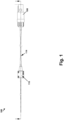
- Figure 1 is guide wire system 100 according to an example
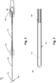
- Figure 2 is a cross-sectional view taken along line A-A of the guide wire system of Figure 1
- the guide wire system 100 includes a guide wire 102 having a distal end 104 and a proximal end 106.
- the guide wire system 100 further includes a first connector 108 coupled to the proximal end 106 of the guide wire 102, and a second connector 110 coupled to the guide wire 102 between the distal end 104 and the proximal end 106.
- An electromagnetic sensor 112 is coupled to the distal end 104 of the guide wire 102.
- the guide wire system 100 further includes a polymeric tube 114 surrounding at least a portion of the guide wire 102 and at least a portion of the electromagnetic sensor 112.
- the guide wire system 100 is discarded after each procedure.
- the guide wire system 100 can be sanitized and reused after each procedure.
- the guide wire 102 comprises a superelastic material.
- a superelastic material deforms reversibly to high strains (up to 10%) by the creation of a stress-induced phase.
- the new phase becomes unstable and the material regains its original shape automatically.
- the guide wire 102 is configured to (i) transition from a first configuration to a second configuration responsive to a force applied to the guide wire 102, and (ii) return from the second configuration to the first configuration responsive to the force being removed from the guide wire 102.
- the guide wire 102 has a straight shape in the first configuration and a bent shape in the second configuration.
- the superelasticity of the guide wire 102 provides kink resistance and tensile strength to the guide wire system 100.
- the superelastic material comprises a nickel titanium alloy, such as nitinol. Other superelastic materials are possible as well.
- the guide wire 102 can include a lubricious coating that reduces friction between the guide wire 102 and other components of the guide wire system 100.
- a diameter of the guide wire 102 ranges from about 0.4 mm to about 1 mm.
- a stiffness of the guide wire 102 is constant along an entire length of the guide wire 102 from the proximal end 106 to the distal end 104. In another example, a stiffness of a distal portion of the guide wire 102 is less than a stiffness of a proximal portion of the guide wire 102. In such an example, a length of the distal portion of the guide wire 102 is less than a length of the proximal portion of the guide wire 102. The reduced stiffness of the distal portion of the guide wire 102 may provide increased flexibility of the distal portion of the guide wire 102, which may be advantageous in certain use cases.
- a diameter of the guide wire 102 is constant along an entire length of the guide wire 102 from the proximal end 106 to the distal end 104. In another example, a diameter of a distal portion of the guide wire 102 is less than a diameter of a proximal portion of the guide wire 102. In such an example, a length of the distal portion of the guide wire 102 is less than a length of the proximal portion of the guide wire 102. The reduced diameter at the distal portion of the guide wire 102 may provide increased flexibility of the distal portion of the guide wire 102, which may be advantageous in certain use cases.
- the guide wire system 100 includes the first connector 108 coupled to the proximal end 106 of the guide wire 102.
- the first connector 108 comprises a pin connector, such as a 10-pin connector as a non-limiting example.
- the polymeric tube 114 surrounds at least a portion of the first connector 108, and the first connector 108 is secured to the proximal end 106 of the guide wire 102 via a heat bond between the polymeric tube 114 and the guide wire 102.
- the guide wire system 100 further includes a second polymeric tube positioned around the guide wire 102 between the first connector 108 and the second connector 110.
- the first connector 108 can include a flexible circuit that includes a memory chip configured to transmit an identification of the guide wire system 100 to an image guided surgery system when the first connector 108 is coupled to the image guided surgery system.
- the flexible circuit comprises an electronic circuit that is assembled by mounting electronic devices on flexible plastic substrates.
- the flexible plastic substrate can be formed from at least one material chosen from polyimide, Polyether ether ketone, and transparent conductive polyester film. Such a design enables the circuit board to conform to a desired shape, or to flex during its use.
- the guide wire system 100 includes the second connector 110 coupled to the guide wire 102 between the distal end 104 and the proximal end 106.
- the second connector 110 comprises a bayonet connector configured to interact with a complementary bayonet connector of balloon dilation catheter to thereby couple the guide wire system 100 to the balloon dilation catheter.
- the second connector 110 is coupled to a handpiece of balloon dilation catheter. A geometry of the second connector 110 with respect to the balloon dilation catheter allows a user to set a desired distance between the distal end 104 of the guide wire 102 and a distal end of the balloon dilation catheter.
- the distal end 104 of the guide wire 102 is aligned with a distal end of the balloon dilation catheter. In another example, when the second connector 110 is coupled to the balloon dilation catheter, the distal end 104 of the guide wire 102 extends distally from a distal end of the balloon dilation catheter.
- Exemplary balloon dilation catheters and methods of use particularly suited for the dilation of anatomic structures associated with the sinuses and use with the guide wire system 100 are disclosed, for example, in U.S. Pat. No. 8,282,667 which is incorporated by reference herein.
- the guide wire system 100 includes an electromagnetic sensor 112 positioned at the distal end 104 of the guide wire 102.
- the electromagnetic sensor 112 is configured to interact with an image guided surgery system to transmit data to the image guided surgery system indicating a location of the electromagnetic sensor 112. Since the electromagnetic sensor 112 is positioned at the distal end 104 of the guide wire 102, the transmitted location of the electromagnetic sensor 112 corresponds to a location of the distal end 104 of the guide wire 102. As discussed in additional detail below, this information can be used to ensure a device (such as a balloon dilation catheter) is properly positioned in a desired nasal cavity to thereby treat nasal afflictions such as sinusitis.
- a device such as a balloon dilation catheter
- the electromagnetic sensor 112 is potted by an epoxy prior to being coupled to the distal end 104 of the guide wire 102.
- the electromagnetic sensor 112 is coupled to the distal end 104 of the guide wire 102 by being potted by an epoxy. Potting the electromagnetic sensor 112 in an epoxy may provide a more robust sensor that is able to better withstand the rigors of multiple nasal cavity procedures.
- the electromagnetic sensor 112 may be secured to the distal end 104 of the guide wire 102 via a radio frequency (RF) tipping die. Utilizing an RF tipping die provides a benefit of joining the electromagnetic sensor 112 to the distal end 104 of the guide wire 102 without the use of adhesive. Further, the RF tipping die prevents movement of the electromagnetic sensor 112 as the RF tipping die joins the electromagnetic sensor 112 to the polymeric tube 114.
- RF radio frequency
- the guide wire system 100 further includes a camera positioned at the distal end 104 of the guide wire 102.
- the electromagnetic sensor 112 may work in combination with the camera to provide a medical professional with the location of the distal end 104 of the guide wire 102.
- a method of manufacturing the guide wire system 100 of any of the examples described above may include (a) positioning a first connector 108 at a proximal end 106 of a guide wire 102, wherein the guide wire 102 comprises a superelastic material that is configured to (i) transition from a first configuration to a second configuration responsive to a force applied to the guide wire 102 and (ii) return from the second configuration to the first configuration responsive to the force being removed from the guide wire 102, (b) positioning a second connector 110 on the guide wire 102 between a distal end 104 of the guide wire 102 and the proximal end 106 of the guide wire 102, (c) positioning an electromagnetic sensor 112 at the distal end 104 of the guide wire 102, (d) positioning a polymeric tube 114 around at least a portion of the guide wire 102 and at least a portion of the electromagnetic sensor 112, and (e) applying a heat source to at least a portion of the polymeric tube 114.
- applying the heat source to at least a portion of the polymeric tube 114 comprises applying the heat source adjacent the proximal end 106 of the guide wire 102 to secure the first connector 108 to the proximal end 106 of the guide wire 102.
- applying the heat source to at least a portion of the polymeric tube 114 comprises applying the heat source adjacent the distal end 104 of the guide wire 102 to secure the electromagnetic sensor 112 to the distal end 104 of the guide wire 102.
- the electromagnetic sensor 112 is potted in epoxy prior to being coupled to the distal end 104 of the guide wire 102.
- the electromagnetic sensor 112 is coupled to the distal end 104 of the guide wire 102 by being potted in epoxy.
- the electromagnetic sensor 112 is secured to the distal end 104 of the guide wire 102 via a radio frequency tipping die.
- a method of treating a sinus cavity of a subject includes (a) inserting a distal portion of a guide wire system into a lumen of a balloon dilation catheter, the guide wire system including: (i) a guide wire having a distal end and a proximal end, wherein the guide wire comprises a superelastic material that is configured to (1) transition from a first configuration to a second configuration responsive to a force applied to the guide wire and (2) return from the second configuration to the first configuration responsive to the force being removed from the guide wire, (ii) a first connector coupled to the proximal end of the guide wire, (iii) a second connector coupled to the guide wire between the distal end and the proximal end, (iv) an electromagnetic sensor coupled to the distal end of the guide wire, and (v) a polymeric tube surrounding at least a portion of the guide wire and at least a portion of the electromagnetic sensor, and the balloon dilation catheter including: (i) an inner guide member including the lume
- the distal end 104 of the guide wire 102 when the second connector 110 is coupled to the balloon dilation catheter, the distal end 104 of the guide wire 102 is aligned with a distal end of the balloon dilation catheter. In another example, when the second connector 110 is coupled to the balloon dilation catheter, the distal end 104 of the guide wire 102 extends distally from a distal end of the balloon dilation catheter. In one example, the method can further include re-positioning the inner guide member based at least in part on a determined location of the distal end 104 of the guide wire 102 with respect to the sinus cavity.
- another method of treating a sinus cavity of a subject includes (a) inserting a portion of the guide wire system 100 of any of the examples described above into a nostril of the subject, (b) directing the distal end 104 of the guide wire 102 to a drainage pathway of the sinus cavity using data received from the electromagnetic sensor 112, (c) while the distal end 104 of the guide wire 102 is in the drainage pathway, positioning a balloon dilation catheter over the guide wire 102, the balloon dilation catheter including: (i) an inner guide member including a lumen, and (ii) a movable shaft coupled to a balloon and mounted on the inner guide member, wherein the balloon dilation catheter is configured to allow the movable shaft to move along the inner guide member and prevent the movable shaft from rotating around the inner guide member, (d) directing the inner guide member over the guide wire to the drainage pathway of the sinus cavity, (e) advancing the movable shaft and balloon over the inner guide member to place the balloon in the drainage pathway while keeping the
- the distal end 104 of the guide wire 102 when the second connector 110 is coupled to the balloon dilation catheter, the distal end 104 of the guide wire 102 is aligned with a distal end of the balloon dilation catheter. In another example, when the second connector 110 is coupled to the balloon dilation catheter, the distal end 104 of the guide wire 102 extends distally from a distal end of the balloon dilation catheter. In one example, the method can further include re-positioning the inner guide member based at least in part on a determined location of the distal end 104 of the guide wire 102 with respect to the sinus cavity.
- another method of treating a sinus cavity of a subject includes (a) inserting a distal portion of a balloon dilation catheter into a nostril of the subject, the balloon dilation catheter including: (i) an inner guide member including a lumen, and (ii) a movable shaft coupled to a balloon and mounted on the inner guide member, wherein the balloon dilation catheter is configured to allow the movable shaft to move along the inner guide member and prevent the movable shaft from rotating around the inner guide member, (b) directing the inner guide member to a drainage pathway of the sinus cavity, (c) advancing the movable shaft and balloon over the inner guide member to place the balloon in the drainage pathway while keeping the inner guide member static relative to the drainage pathway, (d) while the balloon is in the drainage pathway, inserting the guide wire system 100 of any of the examples described above into the lumen of the inner guide member, (e) advancing the guide wire system through the lumen until the distal end 104 of the guide wire 102 is aligned with
Landscapes
- Health & Medical Sciences (AREA)
- Life Sciences & Earth Sciences (AREA)
- Engineering & Computer Science (AREA)
- Surgery (AREA)
- General Health & Medical Sciences (AREA)
- Public Health (AREA)
- Veterinary Medicine (AREA)
- Animal Behavior & Ethology (AREA)
- Heart & Thoracic Surgery (AREA)
- Biomedical Technology (AREA)
- Medical Informatics (AREA)
- Molecular Biology (AREA)
- Nuclear Medicine, Radiotherapy & Molecular Imaging (AREA)
- Pulmonology (AREA)
- Hematology (AREA)
- Anesthesiology (AREA)
- Oral & Maxillofacial Surgery (AREA)
- Biophysics (AREA)
- Dentistry (AREA)
- Pathology (AREA)
- Electromagnetism (AREA)
- Physics & Mathematics (AREA)
- Otolaryngology (AREA)
- Robotics (AREA)
- Vascular Medicine (AREA)
- Media Introduction/Drainage Providing Device (AREA)
- Surgical Instruments (AREA)
- Ultra Sonic Daignosis Equipment (AREA)
Applications Claiming Priority (3)
| Application Number | Priority Date | Filing Date | Title |
|---|---|---|---|
| US201962899999P | 2019-09-13 | 2019-09-13 | |
| EP20781663.8A EP4027917B1 (de) | 2019-09-13 | 2020-09-14 | Führungsdraht für ein bildgeführtes chirurgisches system und verfahren zur herstellung |
| PCT/US2020/050675 WO2021051060A1 (en) | 2019-09-13 | 2020-09-14 | Image guided surgery system guide wire and methods of manufacture and use |
Related Parent Applications (1)
| Application Number | Title | Priority Date | Filing Date |
|---|---|---|---|
| EP20781663.8A Division EP4027917B1 (de) | 2019-09-13 | 2020-09-14 | Führungsdraht für ein bildgeführtes chirurgisches system und verfahren zur herstellung |
Publications (2)
| Publication Number | Publication Date |
|---|---|
| EP4473997A2 true EP4473997A2 (de) | 2024-12-11 |
| EP4473997A3 EP4473997A3 (de) | 2025-02-26 |
Family
ID=72670799
Family Applications (2)
| Application Number | Title | Priority Date | Filing Date |
|---|---|---|---|
| EP24208847.4A Pending EP4473997A3 (de) | 2019-09-13 | 2020-09-14 | Führungsdraht für ein bildgeführtes chirurgisches system und verfahren zur herstellung und verwendung |
| EP20781663.8A Active EP4027917B1 (de) | 2019-09-13 | 2020-09-14 | Führungsdraht für ein bildgeführtes chirurgisches system und verfahren zur herstellung |
Family Applications After (1)
| Application Number | Title | Priority Date | Filing Date |
|---|---|---|---|
| EP20781663.8A Active EP4027917B1 (de) | 2019-09-13 | 2020-09-14 | Führungsdraht für ein bildgeführtes chirurgisches system und verfahren zur herstellung |
Country Status (7)
| Country | Link |
|---|---|
| US (3) | US11617866B2 (de) |
| EP (2) | EP4473997A3 (de) |
| JP (2) | JP2022548609A (de) |
| KR (1) | KR20220066100A (de) |
| CN (1) | CN114340713B (de) |
| AU (1) | AU2020346080B2 (de) |
| WO (1) | WO2021051060A1 (de) |
Families Citing this family (3)
| Publication number | Priority date | Publication date | Assignee | Title |
|---|---|---|---|---|
| JP2022548609A (ja) | 2019-09-13 | 2022-11-21 | エンテラス メディカル インコーポレイテッド | 画像誘導手術システムのガイドワイヤ並びに製造方法及び使用方法 |
| US12426896B2 (en) | 2020-08-07 | 2025-09-30 | Mighty Oak Medical, Inc. | Drilling depth and control apparatus and methods for using the same |
| US11529147B2 (en) * | 2020-08-07 | 2022-12-20 | Mighty Oak Medical, Inc. | Drilling depth and control apparatus and methods for using the same |
Citations (1)
| Publication number | Priority date | Publication date | Assignee | Title |
|---|---|---|---|---|
| US8282667B2 (en) | 2009-06-05 | 2012-10-09 | Entellus Medical, Inc. | Sinus dilation catheter |
Family Cites Families (35)
| Publication number | Priority date | Publication date | Assignee | Title |
|---|---|---|---|---|
| JPH0951954A (ja) * | 1995-08-15 | 1997-02-25 | Nippon Zeon Co Ltd | ガイドワイヤ固定具およびそれを備えたカテーテルセット |
| US6068623A (en) * | 1997-03-06 | 2000-05-30 | Percusurge, Inc. | Hollow medical wires and methods of constructing same |
| US7720521B2 (en) * | 2004-04-21 | 2010-05-18 | Acclarent, Inc. | Methods and devices for performing procedures within the ear, nose, throat and paranasal sinuses |
| US8702626B1 (en) * | 2004-04-21 | 2014-04-22 | Acclarent, Inc. | Guidewires for performing image guided procedures |
| US20070208252A1 (en) * | 2004-04-21 | 2007-09-06 | Acclarent, Inc. | Systems and methods for performing image guided procedures within the ear, nose, throat and paranasal sinuses |
| US9399121B2 (en) * | 2004-04-21 | 2016-07-26 | Acclarent, Inc. | Systems and methods for transnasal dilation of passageways in the ear, nose or throat |
| US8348858B2 (en) * | 2005-01-05 | 2013-01-08 | Stereotaxis, Inc. | Stent delivery guide wire |
| US20060173382A1 (en) * | 2005-01-31 | 2006-08-03 | John Schreiner | Guidewire with superelastic core |
| US8109953B1 (en) * | 2006-08-14 | 2012-02-07 | Volcano Corporation | Catheter device, hub assembly and method for traversing total occlusions |
| US8239003B2 (en) | 2007-04-16 | 2012-08-07 | General Electric Company | System and method of integrating electromagnetic microsensors in guidewires |
| US9649048B2 (en) * | 2007-11-26 | 2017-05-16 | C. R. Bard, Inc. | Systems and methods for breaching a sterile field for intravascular placement of a catheter |
| US9095685B2 (en) * | 2008-01-23 | 2015-08-04 | Mediguide Ltd. | Sensor mounted flexible guidewire |
| EP2313143B1 (de) * | 2008-08-22 | 2014-09-24 | C.R. Bard, Inc. | Katheteranordnung mit ekg-sensor und magnetischen baugruppen |
| GB2465334B (en) | 2008-10-31 | 2013-02-13 | Daniela Andrich | Catheterisation device |
| US10384039B2 (en) * | 2010-05-14 | 2019-08-20 | C. R. Bard, Inc. | Catheter insertion device including top-mounted advancement components |
| US8764683B2 (en) | 2010-12-29 | 2014-07-01 | Mediguide Ltd. | Medical device guidewire with a position sensor |
| US8676301B2 (en) * | 2011-07-14 | 2014-03-18 | Med Works Limited | Guide wire incorporating a handle |
| CA2856519C (en) * | 2011-11-22 | 2020-11-03 | Ascension Technology Corporation | Tracking a guidewire |
| US9364640B2 (en) * | 2012-05-07 | 2016-06-14 | St. Jude Medical Atrial Fibrillation Division, Inc. | Medical device guidewire with helical cutout and coating |
| CN105392518A (zh) * | 2012-10-02 | 2016-03-09 | 女王医疗中心 | 具有引导线防滑脱特征的脉管通路系统 |
| US9233225B2 (en) * | 2012-11-10 | 2016-01-12 | Curvo Medical, Inc. | Coaxial bi-directional catheter |
| EP3048999A1 (de) * | 2013-09-27 | 2016-08-03 | Acclarent, Inc. | Verbesserter greifvorrichtungen für nasale und nasennebenhöhlensysteme |
| US10441754B2 (en) * | 2014-03-26 | 2019-10-15 | Volcano Corporation | Intravascular devices, systems, and methods having a core wire formed of multiple materials |
| US10238845B2 (en) * | 2014-09-19 | 2019-03-26 | Acclarent, Inc. | Balloon catheter assembly |
| JP6945451B2 (ja) * | 2015-04-14 | 2021-10-06 | コーニンクレッカ フィリップス エヌ ヴェKoninklijke Philips N.V. | コア部材に巻きつけられた通信線の周りに形成されたポリマージャケットを有する血管内デバイス、システム及び方法 |
| US10625062B2 (en) * | 2016-03-08 | 2020-04-21 | Acclarent, Inc. | Dilation catheter assembly with rapid change components |
| US20180085174A1 (en) * | 2016-09-23 | 2018-03-29 | Acclarent, Inc. | Suction device for use in image-guided sinus medical procedure |
| KR101831659B1 (ko) * | 2016-09-29 | 2018-02-23 | 원광대학교산학협력단 | 능동형 가이드 와이어 장치 |
| KR102427995B1 (ko) * | 2017-10-12 | 2022-08-03 | 아사히 인텍크 가부시키가이샤 | 가이드 와이어 |
| US11504510B2 (en) | 2017-10-17 | 2022-11-22 | Innovex Medical Co., Ltd. | Dilatable balloon catheter |
| US10974034B2 (en) * | 2017-12-11 | 2021-04-13 | Acclarent, Inc. | Force measurement instrument for sinuplasty procedure |
| US20190192177A1 (en) * | 2017-12-22 | 2019-06-27 | Acclarent, Inc. | Reusable navigation guidewire |
| US20190262512A1 (en) * | 2018-02-27 | 2019-08-29 | Acclarent, Inc. | Medical Instrument with Self-Collapsing Channel |
| US20190261886A1 (en) * | 2018-02-27 | 2019-08-29 | Lucent Medical Systems, Inc. | Medical guidewire with electromagnetic trackable element |
| JP2022548609A (ja) | 2019-09-13 | 2022-11-21 | エンテラス メディカル インコーポレイテッド | 画像誘導手術システムのガイドワイヤ並びに製造方法及び使用方法 |
-
2020
- 2020-09-14 JP JP2022516351A patent/JP2022548609A/ja active Pending
- 2020-09-14 WO PCT/US2020/050675 patent/WO2021051060A1/en not_active Ceased
- 2020-09-14 EP EP24208847.4A patent/EP4473997A3/de active Pending
- 2020-09-14 KR KR1020227012139A patent/KR20220066100A/ko active Pending
- 2020-09-14 CN CN202080062655.5A patent/CN114340713B/zh active Active
- 2020-09-14 AU AU2020346080A patent/AU2020346080B2/en active Active
- 2020-09-14 EP EP20781663.8A patent/EP4027917B1/de active Active
- 2020-09-14 US US17/020,077 patent/US11617866B2/en active Active
-
2023
- 2023-03-03 US US18/177,958 patent/US12420066B2/en active Active
-
2025
- 2025-04-28 JP JP2025074620A patent/JP2025121950A/ja active Pending
- 2025-08-25 US US19/308,739 patent/US20250375595A1/en active Pending
Patent Citations (1)
| Publication number | Priority date | Publication date | Assignee | Title |
|---|---|---|---|---|
| US8282667B2 (en) | 2009-06-05 | 2012-10-09 | Entellus Medical, Inc. | Sinus dilation catheter |
Also Published As
| Publication number | Publication date |
|---|---|
| US20210077788A1 (en) | 2021-03-18 |
| WO2021051060A1 (en) | 2021-03-18 |
| AU2020346080A1 (en) | 2022-03-24 |
| CN114340713B (zh) | 2025-02-25 |
| US12420066B2 (en) | 2025-09-23 |
| EP4473997A3 (de) | 2025-02-26 |
| CN114340713A (zh) | 2022-04-12 |
| CA3154493A1 (en) | 2021-03-18 |
| KR20220066100A (ko) | 2022-05-23 |
| JP2022548609A (ja) | 2022-11-21 |
| EP4027917A1 (de) | 2022-07-20 |
| AU2020346080B2 (en) | 2024-02-15 |
| US11617866B2 (en) | 2023-04-04 |
| AU2024202743A1 (en) | 2024-05-16 |
| US20230226325A1 (en) | 2023-07-20 |
| US20250375595A1 (en) | 2025-12-11 |
| JP2025121950A (ja) | 2025-08-20 |
| EP4027917B1 (de) | 2024-10-30 |
Similar Documents
| Publication | Publication Date | Title |
|---|---|---|
| US12420066B2 (en) | Image guided surgery system guide wire and methods of manufacturing and use | |
| US11541214B2 (en) | Balloon dilation catheter for use in sinus passageways | |
| US20250204943A1 (en) | Balloon Dilation Catheter for Use in Sinus Drainage Pathways | |
| AU2024202743B2 (en) | Image guided surgery system guide wire and methods of manufacture and use | |
| CA3154493C (en) | Image guided surgery system guide wire and methods of manufacture and use | |
| JP7742733B2 (ja) | サポートデバイス |
Legal Events
| Date | Code | Title | Description |
|---|---|---|---|
| PUAI | Public reference made under article 153(3) epc to a published international application that has entered the european phase |
Free format text: ORIGINAL CODE: 0009012 |
|
| STAA | Information on the status of an ep patent application or granted ep patent |
Free format text: STATUS: THE APPLICATION HAS BEEN PUBLISHED |
|
| AC | Divisional application: reference to earlier application |
Ref document number: 4027917 Country of ref document: EP Kind code of ref document: P |
|
| AK | Designated contracting states |
Kind code of ref document: A2 Designated state(s): AL AT BE BG CH CY CZ DE DK EE ES FI FR GB GR HR HU IE IS IT LI LT LU LV MC MK MT NL NO PL PT RO RS SE SI SK SM TR |
|
| REG | Reference to a national code |
Ref country code: DE Ref legal event code: R079 Free format text: PREVIOUS MAIN CLASS: A61M0025090000 Ipc: A61B0017240000 |
|
| PUAL | Search report despatched |
Free format text: ORIGINAL CODE: 0009013 |
|
| AK | Designated contracting states |
Kind code of ref document: A3 Designated state(s): AL AT BE BG CH CY CZ DE DK EE ES FI FR GB GR HR HU IE IS IT LI LT LU LV MC MK MT NL NO PL PT RO RS SE SI SK SM TR |
|
| RIC1 | Information provided on ipc code assigned before grant |
Ipc: A61M 25/01 20060101ALN20250123BHEP Ipc: A61B 17/22 20060101ALN20250123BHEP Ipc: A61M 25/09 20060101ALI20250123BHEP Ipc: A61B 90/00 20160101ALI20250123BHEP Ipc: A61B 90/98 20160101ALI20250123BHEP Ipc: A61B 34/20 20160101ALI20250123BHEP Ipc: A61B 17/24 20060101AFI20250123BHEP |
|
| STAA | Information on the status of an ep patent application or granted ep patent |
Free format text: STATUS: REQUEST FOR EXAMINATION WAS MADE |
|
| 17P | Request for examination filed |
Effective date: 20250826 |