EP4471979A1 - Kontaktvorrichtung für ein elektrisches element und antennenmodul damit - Google Patents
Kontaktvorrichtung für ein elektrisches element und antennenmodul damit Download PDFInfo
- Publication number
- EP4471979A1 EP4471979A1 EP23747205.5A EP23747205A EP4471979A1 EP 4471979 A1 EP4471979 A1 EP 4471979A1 EP 23747205 A EP23747205 A EP 23747205A EP 4471979 A1 EP4471979 A1 EP 4471979A1
- Authority
- EP
- European Patent Office
- Prior art keywords
- gasket
- frame
- fastening hole
- electrical member
- contact device
- Prior art date
- Legal status (The legal status is an assumption and is not a legal conclusion. Google has not performed a legal analysis and makes no representation as to the accuracy of the status listed.)
- Pending
Links
Images




Classifications
-
- H—ELECTRICITY
- H01—ELECTRIC ELEMENTS
- H01R—ELECTRICALLY-CONDUCTIVE CONNECTIONS; STRUCTURAL ASSOCIATIONS OF A PLURALITY OF MUTUALLY-INSULATED ELECTRICAL CONNECTING ELEMENTS; COUPLING DEVICES; CURRENT COLLECTORS
- H01R12/00—Structural associations of a plurality of mutually-insulated electrical connecting elements, specially adapted for printed circuits, e.g. printed circuit boards [PCB], flat or ribbon cables, or like generally planar structures, e.g. terminal strips, terminal blocks; Coupling devices specially adapted for printed circuits, flat or ribbon cables, or like generally planar structures; Terminals specially adapted for contact with, or insertion into, printed circuits, flat or ribbon cables, or like generally planar structures
- H01R12/70—Coupling devices
- H01R12/71—Coupling devices for rigid printing circuits or like structures
- H01R12/712—Coupling devices for rigid printing circuits or like structures co-operating with the surface of the printed circuit or with a coupling device exclusively provided on the surface of the printed circuit
- H01R12/714—Coupling devices for rigid printing circuits or like structures co-operating with the surface of the printed circuit or with a coupling device exclusively provided on the surface of the printed circuit with contacts abutting directly the printed circuit; Button contacts therefore provided on the printed circuit
-
- H—ELECTRICITY
- H01—ELECTRIC ELEMENTS
- H01Q—ANTENNAS, i.e. RADIO AERIALS
- H01Q1/00—Details of, or arrangements associated with, antennas
- H01Q1/12—Supports; Mounting means
- H01Q1/20—Resilient mountings
-
- H—ELECTRICITY
- H01—ELECTRIC ELEMENTS
- H01Q—ANTENNAS, i.e. RADIO AERIALS
- H01Q1/00—Details of, or arrangements associated with, antennas
- H01Q1/005—Damping of vibrations; Means for reducing wind-induced forces
-
- H—ELECTRICITY
- H01—ELECTRIC ELEMENTS
- H01R—ELECTRICALLY-CONDUCTIVE CONNECTIONS; STRUCTURAL ASSOCIATIONS OF A PLURALITY OF MUTUALLY-INSULATED ELECTRICAL CONNECTING ELEMENTS; COUPLING DEVICES; CURRENT COLLECTORS
- H01R12/00—Structural associations of a plurality of mutually-insulated electrical connecting elements, specially adapted for printed circuits, e.g. printed circuit boards [PCB], flat or ribbon cables, or like generally planar structures, e.g. terminal strips, terminal blocks; Coupling devices specially adapted for printed circuits, flat or ribbon cables, or like generally planar structures; Terminals specially adapted for contact with, or insertion into, printed circuits, flat or ribbon cables, or like generally planar structures
- H01R12/70—Coupling devices
- H01R12/7076—Coupling devices for connection between PCB and component, e.g. display
-
- H—ELECTRICITY
- H01—ELECTRIC ELEMENTS
- H01R—ELECTRICALLY-CONDUCTIVE CONNECTIONS; STRUCTURAL ASSOCIATIONS OF A PLURALITY OF MUTUALLY-INSULATED ELECTRICAL CONNECTING ELEMENTS; COUPLING DEVICES; CURRENT COLLECTORS
- H01R13/00—Details of coupling devices of the kinds covered by groups H01R12/70 or H01R24/00 - H01R33/00
- H01R13/02—Contact members
- H01R13/22—Contacts for co-operating by abutting
- H01R13/24—Contacts for co-operating by abutting resilient; resiliently-mounted
- H01R13/2407—Contacts for co-operating by abutting resilient; resiliently-mounted characterized by the resilient means
- H01R13/2414—Contacts for co-operating by abutting resilient; resiliently-mounted characterized by the resilient means conductive elastomers
-
- H—ELECTRICITY
- H01—ELECTRIC ELEMENTS
- H01R—ELECTRICALLY-CONDUCTIVE CONNECTIONS; STRUCTURAL ASSOCIATIONS OF A PLURALITY OF MUTUALLY-INSULATED ELECTRICAL CONNECTING ELEMENTS; COUPLING DEVICES; CURRENT COLLECTORS
- H01R13/00—Details of coupling devices of the kinds covered by groups H01R12/70 or H01R24/00 - H01R33/00
- H01R13/02—Contact members
- H01R13/22—Contacts for co-operating by abutting
- H01R13/24—Contacts for co-operating by abutting resilient; resiliently-mounted
- H01R13/2435—Contacts for co-operating by abutting resilient; resiliently-mounted with opposite contact points, e.g. C beam
-
- H—ELECTRICITY
- H01—ELECTRIC ELEMENTS
- H01R—ELECTRICALLY-CONDUCTIVE CONNECTIONS; STRUCTURAL ASSOCIATIONS OF A PLURALITY OF MUTUALLY-INSULATED ELECTRICAL CONNECTING ELEMENTS; COUPLING DEVICES; CURRENT COLLECTORS
- H01R2201/00—Connectors or connections adapted for particular applications
- H01R2201/02—Connectors or connections adapted for particular applications for antennas
Definitions
- Embodiments of the present disclosure relate to an electrical member contact device and an antenna module comprising same, and more particularly, to an electrical member contact device that protects the contact stability of a contact point between an antenna contact device and a substrate from external environmental factors such as vibration by improving the shape of a contact part, and an antenna module comprising same.
- vehicle antennas refer to various types of antennas mounted inside/outside of a vehicle for communication between wireless communication devices used in the vehicle.
- wireless communication devices used in a vehicle such as AM/FM radios, digital multimedia broadcast (DMB) receivers, global positioning systems (GPS), and vehicle mobile communication devices are extensively used and diversified, there are rapidly increasing requests for vehicle antenna manufacturing techniques of supporting multiple frequency bands while improving durability against vibration and shock occurring in vehicle environments and ensuring the stability and reliability of an antenna operation.
- DMB digital multimedia broadcast
- GPS global positioning systems
- the related arts have adopted a feeding method using the restoring force of a part of an antenna radiator.
- the restoring force is reduced due to long-term use.
- a feeding area is in the form of a contact point, there is a problem in that contact resistance increases due to environmental factors such as external shock or vibration.
- An object of the present disclosure is to provide an electrical member contact device capable of improving the stability and reliability of an antenna operation despite of external shock and vibration by improving a feeding structure of an antenna, and an antenna module comprising same.
- An object of the present disclosure is to provide an electrical member contact device capable of providing measures for preventing an antenna radiator from being separated from a gasket when the restoring force of the antenna radiator is reduced due to long-term used, and an antenna module comprising same.
- the frame may be curved past the first surface being the upper part of the gasket, may protrude out of the fastening hole by penetrating the fastening hole, and may be curved again so that an end of the frame is fixed to the gasket.
- the frame may be made of an elastic material.
- the gasket may be made of an elastic material.
- the gasket may include a fitting guide part provided in a direction penetrating the fastening hole so that the end of the frame is fixed by fitting into the gasket.
- the gasket may include a second surface located facing the first surface and provided to be electrically conductive in contact with a substrate.
- the frame may include: a contact part formed in a 'C' shape while surrounding the first surface and the third surface; and a support part electrically connected to the contact part, arranged between the third surface and the fourth surface, and formed in a 'C' shape to form a curve protruding out of the fastening hole, an end of the support part being fixed to the gasket.
- the contact part may be connected to the support part in a region where the third surface is arranged.
- the frame may be curved past the first surface being the upper part of the gasket, may protrude out of the fastening hole by penetrating the fastening hole, and may be curved again so that an end of the frame is fixed to the gasket.
- the frame may be made of an elastic material.
- the gasket may be made of an elastic material.
- the gasket may include a fitting guide part provided in a direction penetrating the fastening hole so that the end of the frame is fixed by fitting into the gasket.
- the frame may include a protrusion formed to protrude into contact with a side surface of the gasket in order to fix the frame.
- the gasket may include a second surface located facing the first surface and provided to be electrically conductive in contact with a substrate, and the fastening hole may include: a third surface formed on an inner surface of the fastening hole and adjacent to the first surface; and a fourth surface formed on the inner surface of the fastening hole, facing the third surface, and adjacent to the second surface.
- the frame may include: a contact part formed in a 'C' shape while surrounding the first surface and the third surface; and a support part electrically connected to the contact part, arranged between the third surface and the fourth surface, and formed in a 'C' shape to form a curve protruding out of the fastening hole, an end of the support part being fixed to the gasket.
- a second surface of the gasket comes into contact with the substrate.
- a contact area between the substrate and the gasket can be expanded, and separate components such as a feeding pad between the substrate and the gasket are not required.
- an electrical connection between a frame fastened to the gasket and the substrate can be stably maintained against external shock or vibration, and since a separate feeding pad is not required for the electrical connection between the substrate and the gasket, a manufacturing process such as an SMT process is omitted, so that the manufacturing cost can be reduced.
- a protrusion provided on a support part of the frame protrudes from the frame to contact the side surface of the gasket.
- the gasket is provided with a fitting guide part and is configured so that the support part is fitted adjacent to a fourth surface of the gasket.
- Term “and/or” used in the present specification includes each of mentioned components and one or more combinations thereof.
- terms “first” and “second” are used to describe various components, the components are not limited by the terms. The terms are used only to distinguish one component from another component. Therefore, a first component described below may be a second component within the technical idea of the present disclosure.
- Term “horizontal direction” used in the following description means a front, rear, left or right direction with no change in the position in an upward or downward direction
- term “vertical direction” used in the following description means an upward or downward direction with no change in the position in the front, rear, left or right direction.
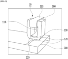
- FIG. 1 is a perspective view of an antenna module 1 including an electrical member contact device according to embodiments of the present disclosure.
Landscapes
- Details Of Aerials (AREA)
Applications Claiming Priority (2)
| Application Number | Priority Date | Filing Date | Title |
|---|---|---|---|
| KR1020220012367A KR102656046B1 (ko) | 2022-01-27 | 2022-01-27 | 전기부재 접촉 장치 및 이를 포함하는 안테나 모듈 |
| PCT/KR2023/000416 WO2023146162A1 (ko) | 2022-01-27 | 2023-01-10 | 전기부재 접촉 장치 및 이를 포함하는 안테나 모듈 |
Publications (2)
| Publication Number | Publication Date |
|---|---|
| EP4471979A1 true EP4471979A1 (de) | 2024-12-04 |
| EP4471979A4 EP4471979A4 (de) | 2025-05-07 |
Family
ID=87471822
Family Applications (1)
| Application Number | Title | Priority Date | Filing Date |
|---|---|---|---|
| EP23747205.5A Pending EP4471979A4 (de) | 2022-01-27 | 2023-01-10 | Kontaktvorrichtung für ein elektrisches element und antennenmodul damit |
Country Status (5)
| Country | Link |
|---|---|
| US (1) | US20250112352A1 (de) |
| EP (1) | EP4471979A4 (de) |
| KR (1) | KR102656046B1 (de) |
| CN (1) | CN118891786A (de) |
| WO (1) | WO2023146162A1 (de) |
Family Cites Families (9)
| Publication number | Priority date | Publication date | Assignee | Title |
|---|---|---|---|---|
| AU7281698A (en) * | 1997-05-06 | 1998-11-27 | Gryphics, Inc. | Multi-mode compliant connector and replaceable chip module utilizing the same |
| KR100989547B1 (ko) * | 2008-05-19 | 2010-10-25 | 박진우 | 안테나 접속장치 |
| KR200458069Y1 (ko) | 2010-03-16 | 2012-01-18 | 주식회사 이엠따블유 | 안테나 캐리어, 안테나 방사체, 및 이를 구비한 내장형 안테나 |
| KR101049545B1 (ko) * | 2010-07-07 | 2011-07-14 | 강태석 | 안테나 접속장치 |
| KR101123423B1 (ko) * | 2010-09-03 | 2012-03-23 | 김연수 | 휴대폰용 안테나 접속 장치 |
| KR101033193B1 (ko) * | 2010-10-14 | 2011-05-06 | 주식회사 이노칩테크놀로지 | 전자파 차폐 가스켓 |
| JP2016208291A (ja) * | 2015-04-23 | 2016-12-08 | ミツミ電機株式会社 | アンテナ装置 |
| US11258163B2 (en) * | 2018-08-30 | 2022-02-22 | Apple Inc. | Housing and antenna architecture for mobile device |
| KR102340421B1 (ko) * | 2019-06-12 | 2021-12-17 | 조인셋 주식회사 | 부착 강도가 향상된 솔더링이 가능한 전기전도성 개스킷 |
-
2022
- 2022-01-27 KR KR1020220012367A patent/KR102656046B1/ko active Active
-
2023
- 2023-01-10 CN CN202380026938.8A patent/CN118891786A/zh active Pending
- 2023-01-10 EP EP23747205.5A patent/EP4471979A4/de active Pending
- 2023-01-10 WO PCT/KR2023/000416 patent/WO2023146162A1/ko not_active Ceased
- 2023-01-10 US US18/833,813 patent/US20250112352A1/en active Pending
Also Published As
| Publication number | Publication date |
|---|---|
| KR102656046B1 (ko) | 2024-04-09 |
| WO2023146162A1 (ko) | 2023-08-03 |
| US20250112352A1 (en) | 2025-04-03 |
| EP4471979A4 (de) | 2025-05-07 |
| KR20230115651A (ko) | 2023-08-03 |
| CN118891786A (zh) | 2024-11-01 |
Similar Documents
| Publication | Publication Date | Title |
|---|---|---|
| US8026864B2 (en) | Antenna device, antenna element and antenna module | |
| EP1861893B1 (de) | Patch-antenne mit gegengewicht zur elektromagnetischen abschirmung | |
| US12199332B2 (en) | Antenna device for vehicle | |
| US10008768B2 (en) | Capacitively shielded housing, in particular capacitively shielded component housing for an antenna device | |
| KR101814301B1 (ko) | 다중대역 차량 안테나 조립체 | |
| CN103918126A (zh) | 具有接地的屏蔽/外壳上的gps天线 | |
| CN113839222B (zh) | 天线装置 | |
| US7078620B2 (en) | Mounting structure of on-vehicle electronic circuit unit | |
| KR20050043701A (ko) | 다중 주파수 안테나 | |
| KR101153165B1 (ko) | 인쇄회로기판을 이용한 고주파 통신선로 | |
| EP4471979A1 (de) | Kontaktvorrichtung für ein elektrisches element und antennenmodul damit | |
| US7646350B2 (en) | Antenna structure | |
| CN108565552B (zh) | 天线装置、连接结构及终端设备 | |
| US20040075612A1 (en) | Antenna device | |
| KR102278616B1 (ko) | 안테나 디바이스 및 이를 포함하는 차량 | |
| US20220376382A1 (en) | Antenna module for small device | |
| US20110075375A1 (en) | Tuner module capable of preventing a heat conductive sheet from arising | |
| CN220527199U (zh) | 平板型双频贴片天线 | |
| US6735308B1 (en) | Mobile telephone connector module | |
| US12327912B2 (en) | Vehicle antenna module | |
| US6940459B2 (en) | Antenna assembly with electrical connectors | |
| KR20170084794A (ko) | 안테나 모듈 | |
| US8681054B2 (en) | PIFA/monopole hybrid antenna and mobile communications device having the same | |
| WO2001091228A1 (en) | Antenna arrangement | |
| KR102278617B1 (ko) | 안테나 디바이스 및 이를 포함하는 차량 |
Legal Events
| Date | Code | Title | Description |
|---|---|---|---|
| STAA | Information on the status of an ep patent application or granted ep patent |
Free format text: STATUS: THE INTERNATIONAL PUBLICATION HAS BEEN MADE |
|
| PUAI | Public reference made under article 153(3) epc to a published international application that has entered the european phase |
Free format text: ORIGINAL CODE: 0009012 |
|
| STAA | Information on the status of an ep patent application or granted ep patent |
Free format text: STATUS: REQUEST FOR EXAMINATION WAS MADE |
|
| 17P | Request for examination filed |
Effective date: 20240806 |
|
| AK | Designated contracting states |
Kind code of ref document: A1 Designated state(s): AL AT BE BG CH CY CZ DE DK EE ES FI FR GB GR HR HU IE IS IT LI LT LU LV MC ME MK MT NL NO PL PT RO RS SE SI SK SM TR |
|
| DAV | Request for validation of the european patent (deleted) | ||
| DAX | Request for extension of the european patent (deleted) | ||
| A4 | Supplementary search report drawn up and despatched |
Effective date: 20250403 |
|
| RIC1 | Information provided on ipc code assigned before grant |
Ipc: H01R 13/24 20060101ALI20250328BHEP Ipc: H01R 12/71 20110101ALI20250328BHEP Ipc: H01R 12/70 20110101ALI20250328BHEP Ipc: H01Q 1/00 20060101ALI20250328BHEP Ipc: H01Q 1/20 20060101AFI20250328BHEP |