EP4471659A1 - Erfassungsvorrichtung zur identifikation eines von einer fördereinrichtung transportierten objekts - Google Patents
Erfassungsvorrichtung zur identifikation eines von einer fördereinrichtung transportierten objekts Download PDFInfo
- Publication number
- EP4471659A1 EP4471659A1 EP23175995.2A EP23175995A EP4471659A1 EP 4471659 A1 EP4471659 A1 EP 4471659A1 EP 23175995 A EP23175995 A EP 23175995A EP 4471659 A1 EP4471659 A1 EP 4471659A1
- Authority
- EP
- European Patent Office
- Prior art keywords
- detection device
- designed
- microphone
- value
- identification
- Prior art date
- Legal status (The legal status is an assumption and is not a legal conclusion. Google has not performed a legal analysis and makes no representation as to the accuracy of the status listed.)
- Granted
Links
Images


Classifications
-
- G—PHYSICS
- G06—COMPUTING OR CALCULATING; COUNTING
- G06K—GRAPHICAL DATA READING; PRESENTATION OF DATA; RECORD CARRIERS; HANDLING RECORD CARRIERS
- G06K7/00—Methods or arrangements for sensing record carriers, e.g. for reading patterns
- G06K7/02—Methods or arrangements for sensing record carriers, e.g. for reading patterns by pneumatic or hydraulic means, e.g. sensing punched holes with compressed air; by sonic means ; by ultrasonic means
-
- G—PHYSICS
- G06—COMPUTING OR CALCULATING; COUNTING
- G06V—IMAGE OR VIDEO RECOGNITION OR UNDERSTANDING
- G06V10/00—Arrangements for image or video recognition or understanding
- G06V10/20—Image preprocessing
- G06V10/255—Detecting or recognising potential candidate objects based on visual cues, e.g. shapes
-
- G—PHYSICS
- G01—MEASURING; TESTING
- G01V—GEOPHYSICS; GRAVITATIONAL MEASUREMENTS; DETECTING MASSES OR OBJECTS; TAGS
- G01V1/00—Seismology; Seismic or acoustic prospecting or detecting
- G01V1/001—Acoustic presence detection
-
- G—PHYSICS
- G06—COMPUTING OR CALCULATING; COUNTING
- G06K—GRAPHICAL DATA READING; PRESENTATION OF DATA; RECORD CARRIERS; HANDLING RECORD CARRIERS
- G06K7/00—Methods or arrangements for sensing record carriers, e.g. for reading patterns
- G06K7/08—Methods or arrangements for sensing record carriers, e.g. for reading patterns by means detecting the change of an electrostatic or magnetic field, e.g. by detecting change of capacitance between electrodes
- G06K7/082—Methods or arrangements for sensing record carriers, e.g. for reading patterns by means detecting the change of an electrostatic or magnetic field, e.g. by detecting change of capacitance between electrodes using inductive or magnetic sensors
- G06K7/087—Methods or arrangements for sensing record carriers, e.g. for reading patterns by means detecting the change of an electrostatic or magnetic field, e.g. by detecting change of capacitance between electrodes using inductive or magnetic sensors flux-sensitive, e.g. magnetic, detectors
-
- G—PHYSICS
- G06—COMPUTING OR CALCULATING; COUNTING
- G06K—GRAPHICAL DATA READING; PRESENTATION OF DATA; RECORD CARRIERS; HANDLING RECORD CARRIERS
- G06K7/00—Methods or arrangements for sensing record carriers, e.g. for reading patterns
- G06K7/10—Methods or arrangements for sensing record carriers, e.g. for reading patterns by electromagnetic radiation, e.g. optical sensing; by corpuscular radiation
- G06K7/10009—Methods or arrangements for sensing record carriers, e.g. for reading patterns by electromagnetic radiation, e.g. optical sensing; by corpuscular radiation sensing by radiation using wavelengths larger than 0.1 mm, e.g. radio-waves or microwaves
- G06K7/10297—Methods or arrangements for sensing record carriers, e.g. for reading patterns by electromagnetic radiation, e.g. optical sensing; by corpuscular radiation sensing by radiation using wavelengths larger than 0.1 mm, e.g. radio-waves or microwaves arrangements for handling protocols designed for non-contact record carriers such as RFIDs NFCs, e.g. ISO/IEC 14443 and 18092
-
- G—PHYSICS
- G06—COMPUTING OR CALCULATING; COUNTING
- G06K—GRAPHICAL DATA READING; PRESENTATION OF DATA; RECORD CARRIERS; HANDLING RECORD CARRIERS
- G06K7/00—Methods or arrangements for sensing record carriers, e.g. for reading patterns
- G06K7/10—Methods or arrangements for sensing record carriers, e.g. for reading patterns by electromagnetic radiation, e.g. optical sensing; by corpuscular radiation
- G06K7/10009—Methods or arrangements for sensing record carriers, e.g. for reading patterns by electromagnetic radiation, e.g. optical sensing; by corpuscular radiation sensing by radiation using wavelengths larger than 0.1 mm, e.g. radio-waves or microwaves
- G06K7/10366—Methods or arrangements for sensing record carriers, e.g. for reading patterns by electromagnetic radiation, e.g. optical sensing; by corpuscular radiation sensing by radiation using wavelengths larger than 0.1 mm, e.g. radio-waves or microwaves the interrogation device being adapted for miscellaneous applications
- G06K7/10415—Methods or arrangements for sensing record carriers, e.g. for reading patterns by electromagnetic radiation, e.g. optical sensing; by corpuscular radiation sensing by radiation using wavelengths larger than 0.1 mm, e.g. radio-waves or microwaves the interrogation device being adapted for miscellaneous applications the interrogation device being fixed in its position, such as an access control device for reading wireless access cards, or a wireless ATM
- G06K7/10425—Methods or arrangements for sensing record carriers, e.g. for reading patterns by electromagnetic radiation, e.g. optical sensing; by corpuscular radiation sensing by radiation using wavelengths larger than 0.1 mm, e.g. radio-waves or microwaves the interrogation device being adapted for miscellaneous applications the interrogation device being fixed in its position, such as an access control device for reading wireless access cards, or a wireless ATM the interrogation device being arranged for interrogation of record carriers passing by the interrogation device
- G06K7/10435—Methods or arrangements for sensing record carriers, e.g. for reading patterns by electromagnetic radiation, e.g. optical sensing; by corpuscular radiation sensing by radiation using wavelengths larger than 0.1 mm, e.g. radio-waves or microwaves the interrogation device being adapted for miscellaneous applications the interrogation device being fixed in its position, such as an access control device for reading wireless access cards, or a wireless ATM the interrogation device being arranged for interrogation of record carriers passing by the interrogation device the interrogation device being positioned close to a conveyor belt or the like on which moving record carriers are passing
-
- G—PHYSICS
- G06—COMPUTING OR CALCULATING; COUNTING
- G06K—GRAPHICAL DATA READING; PRESENTATION OF DATA; RECORD CARRIERS; HANDLING RECORD CARRIERS
- G06K7/00—Methods or arrangements for sensing record carriers, e.g. for reading patterns
- G06K7/10—Methods or arrangements for sensing record carriers, e.g. for reading patterns by electromagnetic radiation, e.g. optical sensing; by corpuscular radiation
- G06K7/10009—Methods or arrangements for sensing record carriers, e.g. for reading patterns by electromagnetic radiation, e.g. optical sensing; by corpuscular radiation sensing by radiation using wavelengths larger than 0.1 mm, e.g. radio-waves or microwaves
- G06K7/10366—Methods or arrangements for sensing record carriers, e.g. for reading patterns by electromagnetic radiation, e.g. optical sensing; by corpuscular radiation sensing by radiation using wavelengths larger than 0.1 mm, e.g. radio-waves or microwaves the interrogation device being adapted for miscellaneous applications
- G06K7/10415—Methods or arrangements for sensing record carriers, e.g. for reading patterns by electromagnetic radiation, e.g. optical sensing; by corpuscular radiation sensing by radiation using wavelengths larger than 0.1 mm, e.g. radio-waves or microwaves the interrogation device being adapted for miscellaneous applications the interrogation device being fixed in its position, such as an access control device for reading wireless access cards, or a wireless ATM
- G06K7/10425—Methods or arrangements for sensing record carriers, e.g. for reading patterns by electromagnetic radiation, e.g. optical sensing; by corpuscular radiation sensing by radiation using wavelengths larger than 0.1 mm, e.g. radio-waves or microwaves the interrogation device being adapted for miscellaneous applications the interrogation device being fixed in its position, such as an access control device for reading wireless access cards, or a wireless ATM the interrogation device being arranged for interrogation of record carriers passing by the interrogation device
- G06K7/10435—Methods or arrangements for sensing record carriers, e.g. for reading patterns by electromagnetic radiation, e.g. optical sensing; by corpuscular radiation sensing by radiation using wavelengths larger than 0.1 mm, e.g. radio-waves or microwaves the interrogation device being adapted for miscellaneous applications the interrogation device being fixed in its position, such as an access control device for reading wireless access cards, or a wireless ATM the interrogation device being arranged for interrogation of record carriers passing by the interrogation device the interrogation device being positioned close to a conveyor belt or the like on which moving record carriers are passing
- G06K7/10445—Methods or arrangements for sensing record carriers, e.g. for reading patterns by electromagnetic radiation, e.g. optical sensing; by corpuscular radiation sensing by radiation using wavelengths larger than 0.1 mm, e.g. radio-waves or microwaves the interrogation device being adapted for miscellaneous applications the interrogation device being fixed in its position, such as an access control device for reading wireless access cards, or a wireless ATM the interrogation device being arranged for interrogation of record carriers passing by the interrogation device the interrogation device being positioned close to a conveyor belt or the like on which moving record carriers are passing the record carriers being fixed to further objects, e.g. RFIDs fixed to packages, luggage, mail-pieces or work-pieces transported on a conveyor belt
-
- G—PHYSICS
- G06—COMPUTING OR CALCULATING; COUNTING
- G06K—GRAPHICAL DATA READING; PRESENTATION OF DATA; RECORD CARRIERS; HANDLING RECORD CARRIERS
- G06K7/00—Methods or arrangements for sensing record carriers, e.g. for reading patterns
- G06K7/10—Methods or arrangements for sensing record carriers, e.g. for reading patterns by electromagnetic radiation, e.g. optical sensing; by corpuscular radiation
- G06K7/10544—Methods or arrangements for sensing record carriers, e.g. for reading patterns by electromagnetic radiation, e.g. optical sensing; by corpuscular radiation by scanning of the records by radiation in the optical part of the electromagnetic spectrum
- G06K7/10712—Fixed beam scanning
-
- G—PHYSICS
- G06—COMPUTING OR CALCULATING; COUNTING
- G06K—GRAPHICAL DATA READING; PRESENTATION OF DATA; RECORD CARRIERS; HANDLING RECORD CARRIERS
- G06K7/00—Methods or arrangements for sensing record carriers, e.g. for reading patterns
- G06K7/10—Methods or arrangements for sensing record carriers, e.g. for reading patterns by electromagnetic radiation, e.g. optical sensing; by corpuscular radiation
- G06K7/10544—Methods or arrangements for sensing record carriers, e.g. for reading patterns by electromagnetic radiation, e.g. optical sensing; by corpuscular radiation by scanning of the records by radiation in the optical part of the electromagnetic spectrum
- G06K7/10712—Fixed beam scanning
- G06K7/10722—Photodetector array or CCD scanning
- G06K7/10732—Light sources
-
- G—PHYSICS
- G06—COMPUTING OR CALCULATING; COUNTING
- G06K—GRAPHICAL DATA READING; PRESENTATION OF DATA; RECORD CARRIERS; HANDLING RECORD CARRIERS
- G06K7/00—Methods or arrangements for sensing record carriers, e.g. for reading patterns
- G06K7/10—Methods or arrangements for sensing record carriers, e.g. for reading patterns by electromagnetic radiation, e.g. optical sensing; by corpuscular radiation
- G06K7/10544—Methods or arrangements for sensing record carriers, e.g. for reading patterns by electromagnetic radiation, e.g. optical sensing; by corpuscular radiation by scanning of the records by radiation in the optical part of the electromagnetic spectrum
- G06K7/10821—Methods or arrangements for sensing record carriers, e.g. for reading patterns by electromagnetic radiation, e.g. optical sensing; by corpuscular radiation by scanning of the records by radiation in the optical part of the electromagnetic spectrum further details of bar or optical code scanning devices
- G06K7/10861—Methods or arrangements for sensing record carriers, e.g. for reading patterns by electromagnetic radiation, e.g. optical sensing; by corpuscular radiation by scanning of the records by radiation in the optical part of the electromagnetic spectrum further details of bar or optical code scanning devices sensing of data fields affixed to objects or articles, e.g. coded labels
-
- G—PHYSICS
- G06—COMPUTING OR CALCULATING; COUNTING
- G06K—GRAPHICAL DATA READING; PRESENTATION OF DATA; RECORD CARRIERS; HANDLING RECORD CARRIERS
- G06K7/00—Methods or arrangements for sensing record carriers, e.g. for reading patterns
- G06K7/10—Methods or arrangements for sensing record carriers, e.g. for reading patterns by electromagnetic radiation, e.g. optical sensing; by corpuscular radiation
- G06K7/14—Methods or arrangements for sensing record carriers, e.g. for reading patterns by electromagnetic radiation, e.g. optical sensing; by corpuscular radiation using light without selection of wavelength, e.g. sensing reflected white light
- G06K7/1404—Methods for optical code recognition
- G06K7/1408—Methods for optical code recognition the method being specifically adapted for the type of code
-
- G—PHYSICS
- G06—COMPUTING OR CALCULATING; COUNTING
- G06V—IMAGE OR VIDEO RECOGNITION OR UNDERSTANDING
- G06V10/00—Arrangements for image or video recognition or understanding
- G06V10/20—Image preprocessing
- G06V10/25—Determination of region of interest [ROI] or a volume of interest [VOI]
-
- B—PERFORMING OPERATIONS; TRANSPORTING
- B65—CONVEYING; PACKING; STORING; HANDLING THIN OR FILAMENTARY MATERIAL
- B65G—TRANSPORT OR STORAGE DEVICES, e.g. CONVEYORS FOR LOADING OR TIPPING, SHOP CONVEYOR SYSTEMS OR PNEUMATIC TUBE CONVEYORS
- B65G2203/00—Indexing code relating to control or detection of the articles or the load carriers during conveying
- B65G2203/02—Control or detection
- B65G2203/0208—Control or detection relating to the transported articles
-
- B—PERFORMING OPERATIONS; TRANSPORTING
- B65—CONVEYING; PACKING; STORING; HANDLING THIN OR FILAMENTARY MATERIAL
- B65G—TRANSPORT OR STORAGE DEVICES, e.g. CONVEYORS FOR LOADING OR TIPPING, SHOP CONVEYOR SYSTEMS OR PNEUMATIC TUBE CONVEYORS
- B65G2203/00—Indexing code relating to control or detection of the articles or the load carriers during conveying
- B65G2203/02—Control or detection
- B65G2203/0208—Control or detection relating to the transported articles
- B65G2203/0216—Codes or marks on the article
-
- B—PERFORMING OPERATIONS; TRANSPORTING
- B65—CONVEYING; PACKING; STORING; HANDLING THIN OR FILAMENTARY MATERIAL
- B65G—TRANSPORT OR STORAGE DEVICES, e.g. CONVEYORS FOR LOADING OR TIPPING, SHOP CONVEYOR SYSTEMS OR PNEUMATIC TUBE CONVEYORS
- B65G2203/00—Indexing code relating to control or detection of the articles or the load carriers during conveying
- B65G2203/04—Detection means
-
- B—PERFORMING OPERATIONS; TRANSPORTING
- B65—CONVEYING; PACKING; STORING; HANDLING THIN OR FILAMENTARY MATERIAL
- B65G—TRANSPORT OR STORAGE DEVICES, e.g. CONVEYORS FOR LOADING OR TIPPING, SHOP CONVEYOR SYSTEMS OR PNEUMATIC TUBE CONVEYORS
- B65G2203/00—Indexing code relating to control or detection of the articles or the load carriers during conveying
- B65G2203/04—Detection means
- B65G2203/041—Camera
-
- B—PERFORMING OPERATIONS; TRANSPORTING
- B65—CONVEYING; PACKING; STORING; HANDLING THIN OR FILAMENTARY MATERIAL
- B65G—TRANSPORT OR STORAGE DEVICES, e.g. CONVEYORS FOR LOADING OR TIPPING, SHOP CONVEYOR SYSTEMS OR PNEUMATIC TUBE CONVEYORS
- B65G2203/00—Indexing code relating to control or detection of the articles or the load carriers during conveying
- B65G2203/04—Detection means
- B65G2203/042—Sensors
-
- B—PERFORMING OPERATIONS; TRANSPORTING
- B65—CONVEYING; PACKING; STORING; HANDLING THIN OR FILAMENTARY MATERIAL
- B65G—TRANSPORT OR STORAGE DEVICES, e.g. CONVEYORS FOR LOADING OR TIPPING, SHOP CONVEYOR SYSTEMS OR PNEUMATIC TUBE CONVEYORS
- B65G2203/00—Indexing code relating to control or detection of the articles or the load carriers during conveying
- B65G2203/04—Detection means
- B65G2203/042—Sensors
- B65G2203/046—RFID
Definitions
- the invention relates to a detection device, in particular a code reader, preferably a barcode scanner, with an identification unit for identifying an object transported by a conveyor device, in particular a continuous conveyor, further in particular a roller conveyor, and a method for identifying an object transported by a conveyor device.
- a detection device in particular a code reader, preferably a barcode scanner
- an identification unit for identifying an object transported by a conveyor device, in particular a continuous conveyor, further in particular a roller conveyor, and a method for identifying an object transported by a conveyor device.
- detection devices with light barriers which detect an approaching object by using a light barrier, whereby only when a detection occurs the identification unit is activated in time to identify the object.
- a disadvantage of this known solution for identifying the object is that a separately arranged light barrier must be provided for each detection device, which also entails additional installation effort for the detection device, in particular for the light barrier and the identification unit itself, as well as for the additional cabling required, and additional maintenance effort for such a system.
- the invention is therefore based on the object of creating a device for identifying an object transported by a conveyor device, which device has a simple structure, wherein the disadvantages of the prior art do not occur.
- a detection device with the features of claim 1, and in particular in that the detection device has at least a first microphone and is designed to acoustically detect the object by means of at least the first microphone, in particular during transport, preferably during a movement during transport that causes particular noise, and to initiate an identification process for identifying the object by means of the identification unit only when the object is detected.
- the detection device Due to the acoustic detection by means of at least the first microphone, the detection device according to the invention is designed to detect the presence of the object in a timely manner, in particular in an area in which the object can be identified by the identification unit, without the need for a light barrier.
- the detection can take place in such a timely manner that the identification process can be initiated and the object can be identified by the identification unit before the object moves away from the detection device again due to transport. This simplifies the structure of the detection device as well as the installation and maintenance effort. Since the detection device is also designed to initiate an identification process of the object using the identification unit only when the object is detected, the service life of the detection device can be increased and its energy consumption reduced.
- the acoustic detection can, for example, be based on a noise generated by the object itself.
- the acoustic detection can also be based on a noise caused by a movement during transport, for example a rolling noise from a roller conveyor. It is also conceivable that the acoustic detection can also be based on a noise generated by another sound source and on which the object has an effect.
- the noise can, for example, be industrial noise in a factory hall, which is shielded from the microphone by the object. Consequently, depending on the application, different noises can be used for detection, whereby the decisive factor is that the noise is sufficiently influenced by the object in a characterizing way so that the presence of the object is acoustically perceptible.
- these and other noises which are related to the detection of the object in the sense of the invention are generally referred to as a noise influenced by the object.
- the "presence” refers in particular to the presence in an area in which the object can be identified by the identification unit.
- the identification unit comprises a code reading sensor for identifying the object.
- the identification unit can be designed for operation in an inactive state in which the code reading sensor is inactive and/or a measured value output of the code reading sensor is not processed, and for operation in an active state in which the code reading sensor is active and/or the measured value output of the code reading sensor is processed, wherein the detection device is designed to switch the identification unit from the inactive state to the active state when the object is detected. This enables reliable identification of the object when it is detected. Since the code reading sensor is basically only active if the object has previously been detected, the service life of the code reading sensor can be increased.
- the energy consumption can also be reduced due to the suspended processing and the service life of other components of the detection device, such as a processor responsible for processing the code reading sensor data, can also be increased.
- the identification unit is designed to read out a code attached to the object, in particular by means of the code reading sensor, by means of which code the object can be identified, in particular in order to identify the object.
- a code attached to the object
- specific information can be assigned to the object in a simple manner. Reading this information by the identification unit thus enables particularly simple and reliable identification of the object.
- the code reading sensor is preferably designed as an optical sensor, in particular as a laser scanner, a camera scanner and/or an LED scanner.
- the code reading sensor can comprise a light source, for example a laser, with which the object is illuminated.
- the illumination is preferably linear.
- the code reading sensor can also be designed as an electromagnetic sensor, in particular as an RFID reader. Such sensors enable particularly reliable identification of the object.
- the detection device advantageously comprises a second microphone at a defined distance from the first microphone and is designed to acoustically detect the object using the second microphone, in particular during transport, preferably during a movement during transport that causes noise.
- the first microphone and the second microphone can be designed the same/identical.
- the detection of the object can be improved using the first microphone, the second microphone and the known defined distance between them.
- the detection device is designed to record and evaluate a volume and a pitch of a noise influenced by the object, in particular a transport noise of the object, by means of at least the first microphone and in particular the second microphone, in order to detect the object.
- the detection is thus carried out using two measured variables, which increases the reliability of the detection.
- the detection device can be designed to calculate a distance between the object and the detection device and/or a position of the object and/or a speed of the object and/or a direction of movement, in particular a direction of transport, of the object on the basis of the volume and/or pitch recorded by the first microphone and the second microphone by means of triangulation and/or beamforming. Furthermore, the detection device can be designed to advantageously use the calculated distance to set an autofocus or a scanning frequency of the identification unit, in particular the optical sensor, and/or to advantageously determine the speed via the calculated speed. of the conveyor device. Furthermore, the detection device can be designed to detect a standstill of the conveyor device using at least the first microphone.
- the detection device can comprise further microphones in the form of a microphone array, whereby the reliability of the detection can be increased even further, in particular by means of beamforming.
- Beamforming can amplify noises from an expected area of the room in which the presence of the object is to be detected, and dampen noises from other areas of the room.
- the detection device can also be designed to detect an irregularity in the operating sequence via the calculated distance between the object and the detection device in order to provide additional diagnostic options.
- an object transported at the edge of the conveyor can be detected as it passes the detection device before the object falls off the conveyor, for example.
- the detection device is designed to detect the object when the distance falls below a predetermined distance value and/or the object reaches a predetermined position value.
- this allows the function of a light barrier to be implemented virtually, since, for example, when the predetermined distance value is reached, at which a light barrier is used in conventional systems, the detection according to the invention can take place.
- the detection device is designed to detect the object when the volume exceeds a predefined first limit value and the pitch exceeds a predefined second limit value. Detection therefore only occurs when the respective limit value is exceeded for both measured variables at the same time. It is not important that the limit values are exceeded at the same time, but only that both criteria are met at the same time. This can further increase the reliability of the detection.
- the detection device is also designed to detect the object when a distance between the object and the detection device falls below a predetermined distance value and/or the object reaches a predetermined position value
- the detection device can be designed to use this as an additional criterion in addition to the volume of the predefined first limit value and the pitch of the predefined second limit value being exceeded, wherein the detection device in such an embodiment can be designed such that detection only takes place when all criteria are met at the same time. This can further increase the reliability of the detection.
- the detection device is advantageously designed to end the identification process after the object has been identified, when the volume exceeds a predefined third limit value and the pitch exceeds a predefined fourth limit value, when a preset waiting time has elapsed after the identification, when a preset switch-off time has elapsed after the identification process has been initiated, when the distance exceeds a predetermined second distance value and/or when the object reaches a predetermined second position value.
- the detection device can advantageously be designed to switch the identification unit from the active state to the inactive state in order to terminate the identification process.
- the limit values are predefined in such a way that the limit values have a correlation with each other, which correlation has a value based on the Doppler effect based relationship between the volume and the pitch of the noise influenced by the object, in particular the transport noise of the object, is taken into account when passing the detection device.
- the sound waves of the noise influenced by the object can be compressed in the direction of movement of the object when the object approaches the detection device.
- the recorded volume can increase, whereby the recorded pitch can be higher than when the object is at the level of the detection device.
- a noise that simply becomes louder and does not have the corresponding pitch could then not lead to detection. Since the recorded volume and pitch therefore only lead to detection if they correlate according to the Doppler effect in the object approaching the detection device, the reliability of the detection can be improved even further.
- the detection device can advantageously comprise a memory module on which the volume and the pitch are recorded.
- the limit values, the waiting time, the switch-off time, the distance value, and in particular the second distance value, and/or the position value, and in particular the second position value can be stored on the memory module, in particular by the manufacturer.
- the detection device can be designed such that the limit values, the waiting time, the switch-off time, the distance value, and in particular the second distance value, and/or the position value, and in particular the second position value, are determined during an installation process of the detection device.
- the memory module can be designed for electronic data exchange with an external device. This makes it easy to access the data required in each case, with the electronic data exchange also making it possible to provide the data on the memory module, for example, to another detection device.
- the detection device is designed to store the volume of the noise influenced by the object as a, in particular respective, first reference pattern and the pitch of the noise influenced by the object as a, in particular respective, second reference pattern in the memory module during the installation process, in which the object passes the detection device at least once, by means of at least the first microphone, and in particular the second microphone, in particular for each passage of the object, and to determine the first limit value, and in particular the third limit value, via the at least one, in particular respective, first reference pattern, and to determine the second limit value, and in particular the fourth limit value, via the at least one, in particular respective, second reference pattern.
- This makes it particularly easy to adjust the limit values to the noise influenced by the object, whereby the reliability of the detection can be improved.
- the detection device is advantageously designed to compare the volume of the noise influenced by the object with the at least one, in particular respective, first reference pattern and the pitch of the noise influenced by the object with the at least one, in particular respective, second reference pattern and, depending on whether the comparison matches, to detect the object and/or to end the identification process and/or to reject the identification.
- This makes it possible, for example, to reject an identification if the comparison shows that the detection was made incorrectly, which can reduce the risk of incorrect identification.
- the degree actually required, e.g. the value of the match depends in particular on the respective desired reliability of the detection and can be determined in a simple manner, for example experimentally.
- the detection device preferably has a hardware interface and is designed to output the identification via the hardware interface, in particular to an industrial plant for further processing of the identification, preferably for locating the identified object via the known location of the detection device.
- the identification can thus be output and further processed in a simple manner.
- the detection device advantageously has a housing in which the identification unit and at least the first microphone, and in particular the second microphone and/or the memory module, are arranged. This results in a particularly compact and simple design of the detection device, which also reduces the installation effort.
- the detection device is advantageously designed to filter out the volume and pitch of a noise influenced by the object, in particular before further evaluation, from an ambient noise of the detection device, in particular industrial noise, by means of one or more filters.
- filters tailored to the respective reference pattern can be provided.
- the detection device can be designed to acoustically detect, by means of at least the first microphone, unscheduled states of a system surrounding the detection device, for example by sounding a warning siren of the conveyor device, and to temporally correlate the detected unscheduled state with a standstill of the conveyor device detected by means of at least the first microphone.
- the detection device can thus enable a transparent error analysis.
- the invention further relates to a method for identifying a material conveyed by a conveyor device, in particular a continuous conveyor, further in particular a Roller conveyor, transported object, in particular by means of a detection device corresponding to one of the preceding embodiments, wherein the object is acoustically detected, in particular during transport, and an identification process for identifying the object is initiated only when the object is detected.
- Fig. 1 shows a detection device 11 known from the prior art with an identification unit 13 installed on a conveyor device 17.
- the identification unit 13 is designed to identify an object 19 transported by the conveyor device 17 during transport.
- the object 19 is provided with a barcode 27, by means of which specific information can be assigned to the object 19 in a simple manner.
- An enlarged view of the barcode 27 is shown in Fig. 1 shown in the bottom right.
- the identification unit 13 is designed to read the barcode 27 so that the Object 19 can be identified via the barcode 27.
- the identification unit 13 is only activated when the object 19 is actually located near the detection device 11.
- the detection device 11 comprises a light barrier 15 at a sufficiently large distance from the identification unit 13, by means of which the detection device 11 can detect the approaching object 19 and only activates the identification unit 13 in time when it is detected so that it can identify the object 19 by reading the barcode 27 before the object 19 has passed the detection device 11.
- a disadvantage of this known solution for identifying the object 19, however, is that a light barrier 15 must be provided for each detection device 11, which also entails additional installation effort for the detection device 11, in particular for the light barrier 15 and the identification unit 13 itself, as well as for the additional cabling required, and additional maintenance effort for such a detection device 11.
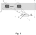
- Fig. 2 shows a detection device 11 according to the invention in the form of a stationary barcode scanner.
- the detection device 11 is arranged on the side of a conveyor device 17, which transports an object 19 in the form of a package in the direction illustrated by the arrow.
- the detection device 11 comprises an identification unit 13 for identifying the object 19 transported by the conveyor device 17 and a first microphone 21.
- the detection device 11 is designed to acoustically detect the object 19 during a noise-causing movement during transport by means of at least the first microphone 21, and to initiate an identification process for identifying the object 19 by means of the identification unit 13 only when the object 19 is detected.
- the identification unit 13 comprises a code reading sensor (not shown) in the form of a laser scanner for identifying the object 19.
- the identification unit 13 is designed for operation in an inactive state in which the code reading sensor is inactive, and for operation in an active state in which the code reading sensor is active.
- the detection device 11 is designed to switch the identification unit 13 from the inactive state to the active state when the object 19 is detected.
- the detection device 11 comprises a control device (not shown).
- the identification unit 13 is designed to use the code reading sensor to read out a code (not shown) attached to the object 19, by means of which code the object 19 can be identified, in order to identify the object 19.
- the detection device 11 has a second microphone 23 at a defined distance from the first microphone 21 and is designed to acoustically detect the object 19 during a noise-causing movement during transport using the second microphone 23.
- the first microphone 21 and the second microphone 23 can be designed in the same way.
- the detection device 11 is designed to record and evaluate a volume and a pitch of a noise influenced by the object 19 by means of the first microphone 21 and the second microphone 23 in order to detect the object 19.
- the noise influenced by the object 19 is the Fig. 2
- the embodiment shown is a transport noise of the object 19, which is illustrated by the circles drawn around the object 19.
- the detection device 11 is designed to use the volume recorded by the first microphone 21 and the second microphone 23 to triangulate on the basis of the time differences to the first microphone 21 and the second microphone 23, the speed of sound and the known defined distance between the first microphone 21 and the second microphone 23 to calculate a distance between the object 19 and the detection device 11.
- Fig. 3 is exemplary for the Fig. 2
- a temporal progression of the volume (b)) and the pitch (c)) is shown, as they are recorded at the location of the detection device 11 by one of the microphones 21, 23 when the object 19, as illustrated by the arrow, is transported by the conveyor device 17 and passes the detection device 11 (a)). Passing includes the object 19 approaching the detection device 11, being at its height, and then moving away from it again. If the object 19 approaches the detection device 11, the volume increases, with the pitch being higher than when the object 19 is at the height of the detection device 11, since the sound waves of the noise influenced by the object 19 are compressed in the direction of movement of the object 19 in the exemplary embodiment shown.
- the volume reaches a maximum, but the pitch is lower than when it is approaching. If the object 19 moves away from the detection device 11 again, the volume decreases, whereby the pitch - since the sound waves of the noise influenced by the object 19 are stretched against the direction of movement of the object 19 in the embodiment shown - is lower than when the object 19 is at the level of the detection device 11.
- the detection device 11 of the embodiment shown is designed to detect the object only if the following three criteria are simultaneously met: If a predefined first limit value of the volume and a predefined second limit value of the pitch are exceeded at the same time, a corresponding first criterion and a corresponding second criterion for detecting the object 19 are met at the same time. It is not important that the limit values are actually exceeded at the same time, but only that both criteria are met at the same time.
- the first limit value and the second limit value are predefined in such a way that the two limit values have a correlation with each other, which correlation is a relationship based on the Doppler effect between the volume and the pitch of the noise influenced by the object 19 when the detection device 11 approaches according to the illustration from Fig. 3 taken into account. If a predetermined distance value is undercut by the calculated distance, a corresponding third criterion is also met.
- the identification unit 13 is thus set to the active state and ready to read the code attached to the object 19 by means of the code reading sensor. In this embodiment, this occurs when the object 19 is at the level of the detection device 11.
- the detection device 11 is designed to end the identification process by means of the control device when the volume falls below a predefined third limit and the pitch falls below a predefined fourth limit and to switch the identification unit 13 from the active state to the inactive state.
- this only occurs when the object 19 reaches the position illustrated by the line CD, since the third limit and the fourth limit are predefined in such a way that the third limit and the fourth limit are only simultaneously undercut from position CD when the object 19 is removed from the detection device 11 due to the noise influenced by the object 19.
- the first and third, as well as the second and fourth limit values can be identical limit values.
- the detection device 11 also comprises a memory module (not shown), on which the volume and the pitch are recorded, wherein the detection device 11 is designed so that the limit values and the distance value are determined during an installation process of the detection device 11.
- the detection device 11 is designed, during the installation process in which the object 19 passes the detection device 11 at least once, to use the first microphone 21 and the second microphone 23 to store the volume of the noise influenced by the object 19 as a respective first reference pattern and the pitch of the noise influenced by the object 19 as a respective second reference pattern in the memory module for each passage of the object 19, and to determine the first limit value and the third limit value via the at least one respective first reference pattern, and to determine the second limit value and the fourth limit value via the at least one respective second reference pattern.
- the object 19 passed the detection device for setting the limit values three times.
- the distance value was determined by an operator in accordance with the first and second limit values thus set. the detection device 11 manually and thus determined by the detection device 11.
- the detection device 11 is designed to compare the volume of the noise influenced by the object 19 with the three respective first reference patterns and the pitch of the noise influenced by the object 19 with the three respective second reference patterns and to reject the identification depending on whether the comparison matches. This means that, for example, an identification can be rejected again if the comparison shows that the detection was made incorrectly, which can reduce the risk of incorrect identification.
- the detection device 11 also has a hardware interface (not shown) and is designed to output the identification via the hardware interface to an industrial plant for locating the identified object 19 via the known location of the detection device 11.
- the detection device 11 also comprises a housing 25, in which housing 25 the identification unit 13, the first microphone 21, the second microphone 23, the memory module, and the hardware interface are arranged. This results in a particularly compact and simple design of the detection device 11, which also reduces the installation effort.
Landscapes
- Engineering & Computer Science (AREA)
- Physics & Mathematics (AREA)
- General Physics & Mathematics (AREA)
- Toxicology (AREA)
- Health & Medical Sciences (AREA)
- Theoretical Computer Science (AREA)
- Electromagnetism (AREA)
- Computer Vision & Pattern Recognition (AREA)
- Artificial Intelligence (AREA)
- General Health & Medical Sciences (AREA)
- Computer Networks & Wireless Communication (AREA)
- Life Sciences & Earth Sciences (AREA)
- Acoustics & Sound (AREA)
- Multimedia (AREA)
- Computer Security & Cryptography (AREA)
- Geology (AREA)
- Remote Sensing (AREA)
- Environmental & Geological Engineering (AREA)
- Geophysics (AREA)
- General Life Sciences & Earth Sciences (AREA)
- Control Of Conveyors (AREA)
Abstract
Description
- Die Erfindung betrifft eine Erfassungsvorrichtung, insbesondere einen Codeleser, vorzugsweise einen Barcode-Scanner, mit einer Identifikationseinheit zur Identifikation eines von einer Fördereinrichtung, insbesondere einem Stetigförderer, weiter insbesondere einem Rollenförderer, transportierten Objekts, sowie ein Verfahren zur Identifikation eines von einer Fördereinrichtung transportierten Objekts.
- Beispielsweise in Werkhallen oder Logistikzentren ist es für einen koordinierten Ablauf wichtig, dass der Aufenthaltsort eines Objekts, wie zum Beispiel eines Pakets, bekannt ist. Gewöhnlich kommen hierzu an Fördereinrichtungen installierte Erfassungsvorrichtungen zum Einsatz, welche das Objekt mittels einer Identifikationseinheit identifizieren und, da der Standort der Erfassungsvorrichtung bekannt ist, damit eine Ortung des Objekts ermöglichen.
- Dabei ist es üblich, die Identifikationseinheit lediglich dann zu aktivieren, wenn sich das Objekt auch tatsächlich in der Nähe der Erfassungsvorrichtung befindet. Ein dauerhafter Betrieb der Identifikationseinheit kann hingegen, insbesondere bei Laser-basierten Identifikationseinheiten, die Lebensdauer der Erfassungsvorrichtung unnötig reduzieren, da die Gefahr für einen Defekt, beispielsweise eines Codelesesensors der Identifikationseinheit, steigt.
- Daher sind Erfassungsvorrichtung mit Lichtschranken bekannt, die ein herannahendes Objekt durch den Einsatz einer Lichtschranke detektieren, wobei lediglich bei einer Detektion die Identifikationseinheit rechtzeitig aktiviert wird, um das Objekt zu identifizieren.
- Nachteilig an dieser bekannten Lösung zur Identifikation des Objekts ist allerdings, dass für jede Erfassungsvorrichtung eine separat anzuordnende Lichtschranke vorgesehen werden muss, womit auch ein zusätzlicher Installationsaufwand für die Erfassungsvorrichtung, insbesondere für die Lichtschranke und die Identifikationseinheit an sich, sowie für die zusätzliche benötigte Verkabelung, und ein zusätzlicher Wartungsaufwand eines solchen Systems einhergeht.
- Der Erfindung liegt daher die Aufgabe zugrunde, eine Vorrichtung zur Identifikation eines von einer Fördereinrichtung transportierten Objekts zu schaffen, welche Vorrichtung einen einfachen Aufbau aufweist, wobei die Nachteile des Stands der Technik nicht auftreten.
- Diese Aufgabe wird durch eine Erfassungsvorrichtung mit den Merkmalen des Anspruchs 1 gelöst, und insbesondere dadurch dass die Erfassungsvorrichtung zumindest ein erstes Mikrofon aufweist und dazu ausgebildet ist, mittels zumindest des ersten Mikrofons das Objekt, insbesondere beim Transport, vorzugsweise während einer, insbesondere Geräusche verursachenden, Bewegung während des Transports, akustisch zu detektieren, und lediglich bei einer Detektion des Objekts einen Identifikationsvorgang zur Identifikation des Objekts mittels der Identifikationseinheit anzustoßen.
- Auf Grund der akustischen Detektion mittels zumindest des ersten Mikrofons ist die erfindungsgemäße Erfassungsvorrichtung dazu ausgebildet, die Anwesenheit des Objekts, insbesondere in einem Bereich, in welchem das Objekt durch die Identifikationseinheit identifiziert werden kann, ohne die Notwendigkeit einer Lichtschranke rechtzeitig zu detektieren. Die Detektion kann dabei so rechtzeitig erfolgen, dass der Identifikationsvorgang angestoßen und das Objekt durch die Identifikationseinheit identifiziert werden kann, bevor sich das Objekt auf Grund des Transports von der Erfassungsvorrichtung wieder entfernt. Hierdurch vereinfacht sich der Aufbau der Erfassungsvorrichtung sowie der Installations- und Wartungsaufwand. Da die Erfassungsvorrichtung ferner dazu ausgebildet ist, lediglich bei einer Detektion des Objekts einen Identifikationsvorgang des Objekts mittels der Identifikationseinheit anzustoßen, kann die Lebensdauer der Erfassungsvorrichtung erhöht und deren Energieverbrauch reduziert werden.
- Die akustische Detektion kann beispielsweise auf einem von dem Objekt selbst erzeugten Geräusch beruhen. Die akustische Detektion kann aber auch auf einem Geräusch beruhen, welches bei einer Bewegung während des Transports verursacht wird, beispielsweise einem Rollgeräusch eines Rollenförderers. Ebenfalls denkbar ist, dass die akustische Detektion auch auf einem Geräusch beruht, welches von einer anderen Schallquelle erzeugt wird und auf welches das Objekt einwirkt. Dabei kann es sich bei dem Geräusch beispielsweise um einen Industrielärm in einer Werkhalle handeln, welcher von dem Objekt gegenüber dem Mikrofon abgeschirmt wird. Folglich können je nach Anwendungsfall verschiedene Geräusche zur Detektion herangezogen werden, wobei maßgeblich ist, dass das Geräusch von dem Objekt hinreichend charakterisierend beeinflusst wird, sodass die Anwesenheit des Objekts akustisch wahrnehmbar ist. Insofern werden diese und auch andere Geräusche, welche im Sinne der Erfindung im Zusammenhang mit der Detektion des Objekts stehen, allgemein als ein von dem Objekt beeinflusstes Geräusch bezeichnet.
- Die "Anwesenheit" bezeichnet dabei insbesondere die Anwesenheit in einem Bereich, in welchem das Objekt durch die Identifikationseinheit identifiziert werden kann.
- Vorteilhafte Ausgestaltungen der Erfindung ergeben sich aus den Unteransprüchen, der Beschreibung und den Figuren.
- Es kann vorgesehen sein, dass die Identifikationseinheit einen Codelesesensor zur Identifikation des Objekts umfasst. Die Identifikationseinheit kann für einen Betrieb in einem inaktiven Zustand, in welchem der Codelesesensor inaktiv ist und/oder eine Messwertausgabe des Codelesesensors nicht verarbeitet wird, und für einen Betrieb einem aktiven Zustand, in welchem der Codelesesensor aktiv ist und/oder die Messwertausgabe des Codelesesensors verarbeitet wird, ausgebildet sein, wobei die Erfassungsvorrichtung dazu ausgebildet ist, bei der Detektion des Objekts die Identifikationseinheit aus dem inaktiven Zustand in den aktiven Zustand zu versetzen. Hierdurch kann bei einer Detektion eine zuverlässige Identifikation des Objekts erfolgen. Da der Codelesesensor grundsätzlich nur aktiv ist, wenn das Objekt zuvor detektiert wurde, kann die Lebensdauer des Codelesesensors erhöht werden. Bei Ausgestaltungen mit einem für einen dauerhaften Betrieb ausgelegten Codelesesensor, kann, wenn lediglich die Messwertausgabe des Codelesesensors nicht verarbeitet wird, auf Grund der ausgesetzten Verarbeitung ebenfalls der Energieverbrauch reduziert und auch die Lebensdauer anderer Komponenten der Erfassungsvorrichtung, wie beispielsweise eines für die Verarbeitung der Codelesesensordaten zuständigen Prozessors, erhöht werden.
- Vorzugsweise ist die Identifikationseinheit dazu ausgebildet, insbesondere mittels des Codelesesensors, einen an dem Objekt angebrachten Code, mittels welchem Code das Objekt identifizierbar ist, auszulesen, insbesondere um das Objekt zu identifizieren. Mittels des Codes können dem Objekt spezifische Informationen auf einfache Weise zugeordnet werden. Deren Auslesung durch die Identifikationseinheit ermöglicht somit eine besonders einfache und zuverlässige Identifikation des Objekts.
- Bevorzugt ist der Codelesesensor als ein optischer Sensor, insbesondere als Laser-Scanner, als Kamera-Scanner und/oder als LED-Scanner, ausgeführt. Der Codelesesensor kann eine Lichtquelle, beispielsweise einen Laser, umfassen, mit welchem das Objekt beleuchtet wird. Die Beleuchtung erfolgt bevorzugt linienförmig. Alternativ kann der Codelesesensor auch als ein elektromagnetischer Sensor, insbesondere als ein RFID Lesegerät, ausgeführt sein. Derartige Sensoren ermöglichen eine besonders zuverlässige Identifikation des Objekts.
- Vorteilhafterweise umfasst die Erfassungsvorrichtung definiert beabstandet zu dem ersten Mikrofon ein zweites Mikrofon und ist dazu ausgebildet, auch mittels des zweiten Mikrofons das Objekt, insbesondere beim Transport, vorzugsweise während einer, insbesondere Geräusche verursachenden, Bewegung während des Transports, akustisch zu detektieren. Das erste Mikrofon und das zweite Mikrofon können dabei gleich/identisch ausgebildet sein. Mittels des ersten Mikrofons, des zweiten Mikrofons und des bekannten definierten Abstands zwischen diesen kann die Detektion des Objekts verbessert werden.
- Bevorzugt ist die Erfassungsvorrichtung dazu ausgebildet, mittels zumindest des ersten Mikrofons, und insbesondere des zweiten Mikrofons, insbesondere jeweils, eine Lautstärke und eine Tonhöhe eines von dem Objekt beeinflussten Geräuschs, insbesondere eines Transportgeräuschs des Objekts, aufzuzeichnen und auszuwerten, um das Objekt zu detektieren. Die Detektion erfolgt somit anhand zweier Messgrößen, wodurch die Zuverlässigkeit der Detektion steigt.
- Weiter kann die Erfassungsvorrichtung dazu ausgebildet sein, auf Grundlage der von dem ersten Mikrofon und dem zweiten Mikrofon jeweils aufgezeichneten Lautstärke und/oder Tonhöhe mittels Triangulation und/oder Beamforming eine Entfernung zwischen dem Objekt und der Erfassungsvorrichtung und/oder eine Position des Objekts und/oder eine Geschwindigkeit des Objekts und/oder eine Bewegungsrichtung, insbesondere eine Transportrichtung, des Objekts zu berechnen. Des Weiteren kann die Erfassungsvorrichtung dazu ausgebildet sein, die berechnete Entfernung vorteilhaft zu einer Einstellung eines Autofokus oder einer Scanfrequenz der Identifikationseinheit, insbesondere des optischen Sensors, zu nutzten und/oder über die berechnete Geschwindigkeit mit Vorteil die Geschwindigkeit der Fördereinrichtung zu bestimmen. Ferner kann die Erfassungsvorrichtung dazu ausgebildet sein, mittels zumindest des ersten Mikrofons einen Stillstand der Fördereinrichtung zu erkennen. Insbesondere kann die Erfassungsvorrichtung zur Detektion noch weitere Mikrofone in Form eines Mikrofon-Arrays umfassen, wodurch die Zuverlässigkeit der Detektion, insbesondere mittels Beamforming, noch weiter erhöht werden kann. Durch das Beamforming können Geräusche aus einem erwarteten Raumbereich, in welchem die Anwesenheit des Objekts detektiert werden soll, verstärkt und Geräusche aus anderen Raumbereichen gedämpft werden.
- Die Erfassungvorrichtung kann auch dazu ausgebildet sein, über die berechnete Entfernung zwischen dem Objekt und der Erfassungsvorrichtung eine Unregelmäßigkeit im Betriebsablauf zu erkennen, um erweitere Diagnosemöglichkeiten bereitzustellen. So kann beispielsweise ein am Rand der Fördereinrichtung transportiertes Objekt beim Passieren der Erfassungseinrichtung erkannt werden, bevor das Objekt beispielsweise von der Fördereinrichtung fällt.
- Bevorzugt ist die Erfassungsvorrichtung dazu ausgebildet, das Objekt zu detektieren, wenn die Entfernung einen vorbestimmten Entfernungswert unterschreitet und/oder das Objekt eine vorgegebenen Positionswert erreicht. Insbesondere hierdurch kann die Funktion einer Lichtschranke virtuell umgesetzt werden, da beispielsweise bei Erreichen des vorbestimmten Entfernungswerts, bei welchem bei herkömmlichen Systemen eine Lichtschranke eingesetzt wird, die erfindungsgemäße Detektion erfolgen kann.
- Vorzugsweise ist die Erfassungsvorrichtung dazu ausgebildet ist, das Objekt zu detektieren, wenn die Lautstärke einen vordefinierten ersten Grenzwert und die Tonhöhe einen vordefinierten zweiten Grenzwert durchtreten. Eine Detektion erfolgt also grundsätzlich nur dann, wenn für beide Messgrößen der jeweilige Grenzwert zugleich durchtreten ist. Dabei kommt es nicht darauf an, dass die Grenzwerte zeitgleich durchtreten werden, sondern lediglich, dass die beiden Kriterien zugleich erfüllt sind. Hierdurch kann die Zuverlässigkeit der Detektion weiter erhöht werden. Falls die Erfassungsvorrichtung auch dazu ausgebildet ist, das Objekt zu detektieren, wenn eine Entfernung zwischen dem Objekt und der Erfassungsvorrichtung einen vorbestimmten Entfernungswert unterschreitet und/oder das Objekt eine vorgegebenen Positionswert erreicht, kann die Erfassungsvorrichtung dazu ausgebildet sein, dies als zusätzliches Kriterium neben dem Durchtreten der Lautstärke des vordefinierten ersten Grenzwerts und der Tonhöhe des vordefinierten zweiten Grenzwerts anzuwenden, wobei die Erfassungsvorrichtung in einer solchen Ausgestaltung dazu ausgebildet sein kann, dass eine Detektion dann nur erfolgt, wenn alle Kriterien zugleich erfüllt sind. Hierdurch kann die Zuverlässigkeit der Detektion noch weiter erhöht werden.
- Mit Vorteil ist die Erfassungsvorrichtung dazu ausgebildet, nach der Identifikation des Objekts, wenn die Lautstärke einen vordefinierten dritten Grenzwert und die Tonhöhe einen vordefinierten vierten Grenzwert durchtreten, wenn nach der Identifikation eine voreingestellte Wartezeit abgelaufen ist, wenn nach dem Anstoßen des Identifikationsvorgangs eine voreingestellte Abschaltzeit abgelaufen ist, wenn die Entfernung einen vorbestimmten zweiten Entfernungswert überschreitet und/oder wenn das Objekt eine vorgegebenen zweiten Positionswert erreicht, den Identifikationsvorgang zu beenden. Hierdurch kann auf einfache Weise die Lebensdauer der Erfassungsvorrichtung erhöht und deren Energieverbrauch reduziert werden.
- Weiter mit Vorteil kann die Erfassungsvorrichtung dazu ausgebildet sein, zum Beenden des Identifikationsvorgangs die Identifikationseinheit aus dem aktiven Zustand in den inaktiven Zustand zu versetzten.
- Bevorzugt sind die Grenzwerte derart vordefiniert, dass die Grenzwerte zueinander eine Korrelation aufweisen, welche Korrelation einen auf dem Dopplereffekt beruhende Beziehung zwischen der Lautstärke und der Tonhöhe des von dem Objekt beeinflussten Geräuschs, insbesondere des Transportgeräuschs des Objekts, beim Passieren der Erfassungsvorrichtung berücksichtigt. Beispielsweise können die Schallwellen des von dem Objekt beeinflussten Geräuschs in Bewegungsrichtung des Objekts gestaucht werden, wenn sich das Objekt der Erfassungsvorrichtung nähert. Dadurch kann, wenn sich das Objekt der Erfassungsvorrichtung nähert, die aufgezeichnete Lautstärke steigen, wobei die aufgezeichnete Tonhöhe höher sein kann, als wenn sich das Objekt auf Höhe der Erfassungsvorrichtung befindet. Ein lediglich lauter werdendes Geräusch, das die entsprechende Tonhöhe nicht aufweist, könnte dann hingegen nicht zu einer Detektion führen. Da die aufgezeichnete Lautstärke und Tonhöhe also grundsätzlich nur dann zu einer Detektion führen, wenn diese dem Dopplereffekt bei dem sich der Erfassungsvorrichtung nähernden Objekt entsprechend korrelieren, kann die Zuverlässigkeit der Detektion noch weiter verbessert werden.
- Vorteilhafterweise kann die Erfassungsvorrichtung ein Speichermodul umfassen, auf welchem die Lautstärke und die Tonhöhe aufgezeichnet werden. Alternativ oder zusätzlich können die Grenzwerte, die Wartezeit, die Abschaltzeit, der Entfernungswert, und insbesondere der zweite Entfernungswert, und/oder der Positionswert, und insbesondere der zweite Positionswert, insbesondere herstellerseitig, auf dem Speichermodul hinterlegt sein. Weiter alternativ oder zusätzlich kann die Erfassungsvorrichtung dazu ausgebildet sein, dass die Grenzwerte, die Wartezeit, die Abschaltzeit, der Entfernungswert, und insbesondere der zweite Entfernungswert, und/oder der Positionswert, und insbesondere der zweite Positionswert, bei einem Installationsvorgang der Erfassungsvorrichtung festgelegt werden. Insbesondere kann das Speichermodul für einen elektronischen Datenaustausch mit einem externen Gerät ausgebildet sein. Hierdurch kann auf einfache Weise auf die jeweils benötigten Daten zugegriffen werden, wobei der elektronische Datenaustausch auch eine Bereitstellung der auf dem Speichermodul befindlichen Daten beispielsweise an eine andere Erfassungsvorrichtung ermöglicht.
- Bevorzugt ist die Erfassungsvorrichtung dazu ausgebildet ist, bei dem Installationsvorgang, bei welchem das Objekt zumindest einmal die Erfassungsvorrichtung passiert, mittels zumindest des ersten Mikrofons, und insbesondere des zweiten Mikrofons, insbesondere jeweils, für jedes Passieren des Objekts die Lautstärke des von dem Objekt beeinflussten Geräuschs als ein, insbesondere jeweiliges, erstes Referenzmuster und die Tonhöhe des von dem Objekt beeinflussten Geräuschs als ein, insbesondere jeweiliges, zweites Referenzmuster in dem Speichermodul abzuspeichern, und über das zumindest eine, insbesondere jeweilige, erste Referenzmuster den ersten Grenzwert, und insbesondere den dritten Grenzwert, zu bestimmen, und über das zumindest eine, insbesondere jeweilige, zweite Referenzmuster den zweiten Grenzwert, und insbesondere den vierten Grenzwert, zu bestimmen. Hierdurch können auf besonders einfache Weise die Grenzwerte auf das von dem Objekt beeinflusste Geräusch abgestimmt werden, wodurch die Zuverlässigkeit der Detektion verbessert werden kann.
- Vorteilhafterweise ist die Erfassungsvorrichtung dazu ausgebildet, die Lautstärke des von dem Objekt beeinflussten Geräuschs mit dem zumindest einen, insbesondere jeweiligen, ersten Referenzmuster und die Tonhöhe des von dem Objekt beeinflussten Geräuschs mit dem zumindest einen, insbesondere jeweiligen, zweiten Referenzmuster zu vergleichen und in Abhängigkeit einer Übereinstimmung des Vergleichs das Objekt zu detektieren und/oder den Identifikationsvorgang zu beenden und/oder die Identifikation zu verwerfen. Hierdurch kann beispielsweise eine Identifikation wieder verworfen werden, wenn der Vergleich ergibt, dass die Detektion fälschlicherweise erfolgte, wodurch das Risiko einer fehlerhaften Identifikation verringert werden kann. Der tatsächlich erforderliche Grad, d.h. beispielsweise der Wert der Übereinstimmung, hängt insbesondere von der jeweiligen gewünschten Zuverlässigkeit der Detektion ab und kann auf einfache Weise beispielsweise experimentell ermittelt werden.
- Bevorzugt weist die Erfassungsvorrichtung eine Hardwareschnittstelle auf und ist dazu ausgebildet, die Identifikation über die Hardwareschnittstelle, insbesondere an eine Industrieanlage zur Weiterverarbeitung der Identifikation, vorzugsweise zur Ortung des identifizierten Objekts über den bekannten Ort der Erfassungsvorrichtung, auszugeben. Dadurch kann die Identifikation auf einfache Weise ausgegeben und weiterverarbeitet werden.
- Mit Vorteil weist die Erfassungsvorrichtung ein Gehäuse auf, in welchem Gehäuse die Identifikationseinheit und zumindest das erste Mikrofon, und insbesondere das zweite Mikrofon und/oder das Speichermodul, angeordnet sind. Hierdurch ergibt sich eine besonders kompakte und einfache Bauweise der Erfassungsvorrichtung, wobei sich außerdem auch der Installationsaufwand verringert.
- Vorteilhafterweise ist die Erfassungsvorrichtung dazu ausgebildet, die Lautstärke und Tonhöhe eines von dem Objekt beeinflussten Geräuschs, insbesondere vor einer weiteren Auswertung, mittels einem oder mehrerer Filter aus einem Umgebungsgeräusch der Erfassungsvorrichtung, insbesondere Industrielärm, herauszufiltern. Hierzu können insbesondere auf das jeweilige Referenzmuster abgestimmte Filter vorgesehen sein.
- Darüber hinaus kann die Erfassungsvorrichtung dazu ausgebildet sein, mittels zumindest des ersten Mikrofons außerplanmäßige Zustände einer die Erfassungsvorrichtung umgebenden Anlage, beispielsweise über ein Ertönen einer Warnsirene der Fördereinrichtung, akustisch zu erkennen und den erkannten außerplanmäßigen Zustand mit einem mittels zumindest des ersten Mikrofons erkannten Stillstand der Fördereinrichtung zeitlich zu korrelieren. Dadurch kann die Erfassungsvorrichtung eine transparente Fehleranalyse ermöglichen.
- Die Erfindung betrifft ferner ein Verfahren zur Identifikation eines von einer Fördereinrichtung, insbesondere einem Stetigförderer, weiter insbesondere einem Rollenförderer, transportierten Objekts, insbesondere mittels einer einer der vorhergehenden Ausführungen entsprechenden Erfassungsvorrichtung, wobei das Objekt, insbesondere beim Transport, akustisch detektiert wird und lediglich bei einer Detektion des Objekts ein Identifikationsvorgang zur Identifikation des Objekts angestoßen wird.
- Generell gelten die Ausführungen zu der erfindungsgemäßen Erfassungsvorrichtung für das erfindungsgemäße Verfahren entsprechend, dies gilt insbesondere hinsichtlich Ausführungsformen und Vorteilen. Zudem versteht es sich, dass sämtliche hierin genannten Merkmale miteinander kombinierbar sind, außer es ist explizit etwas Gegenteiliges angegeben.
- Die Erfindung wird im Folgenden beispielhaft unter Bezugnahme auf die Figuren beschrieben. Es zeigen schematisch
- Fig. 1
- eine aus dem Stand der Technik bekannte Erfassungsvorrichtung,
- Fig. 2
- eine erfindungsgemäße Erfassungsvorrichtung, und
- Fig. 3
- einen zeitlichen Verlauf von Lautstärke und Tonhöhe am Ort der Erfassungsvorrichtung beim Transport des Objekts.
-
Fig. 1 zeigt eine aus dem Stand der Technik bekannte Erfassungsvorrichtung 11 mit einer an einer Fördereinrichtung 17 installierten Identifikationseinheit 13. Die Identifikationseinheit 13 ist dazu ausgebildet, ein von der Fördereinrichtung 17 transportiertes Objekt 19 beim Transport zu identifizieren. Hierzu ist das Objekt 19 mit einem Barcode 27 versehen, mittels welchem dem Objekt 19 spezifische Informationen auf einfache Weise zugeordnet werden können. Eine vergrößerte Ansicht des Barcodes 27 ist inFig. 1 rechts unten zusätzlich dargestellt. Die Identifikationseinheit 13 ist dazu ausgebildet, den Barcode 27 auszulesen, so dass das Objekt 19 über den Barcode 27 identifizierbar ist. Um die Lebensdauer der Erfassungsvorrichtung 11 nicht unnötig zu verringern, ist die Identifikationseinheit 13 lediglich dann aktiviert, wenn sich das Objekt 19 auch tatsächlich in der Nähe der Erfassungsvorrichtung 11 befindet. Hierzu umfasst die Erfassungsvorrichtung 11 in einem ausreichend großen Abstand zur Identifikationseinheit 13 eine Lichtschranke 15, mittels welcher die Erfassungsvorrichtung 11 das herannahende Objekt 19 detektieren kann und lediglich bei einer Detektion die Identifikationseinheit 13 so rechtzeitig aktiviert, dass diese durch das Auslesen des Barcodes 27 das Objekt 19 identifizieren kann, bevor das Objekt 19 die Erfassungsvorrichtung 11 passiert hat. - Nachteilig an dieser bekannten Lösung zur Identifikation des Objekts 19 ist allerdings, dass für jede Erfassungsvorrichtung 11 eine Lichtschranke 15 vorgesehen werden muss, womit auch ein zusätzlicher Installationsaufwand für die Erfassungsvorrichtung 11, insbesondere für die Lichtschranke 15 und die Identifikationseinheit 13 an sich, sowie für die zusätzliche benötigte Verkabelung, und ein zusätzlicher Wartungsaufwand einer solchen Erfassungsvorrichtung 11 einhergeht.
-
Fig. 2 zeigt eine erfindungsgemäße Erfassungsvorrichtung 11 in Form eines stationären Barcode-Scanners. Die Erfassungsvorrichtung 11 ist seitlich an einer Fördereinrichtung 17 angeordnet, welche ein Objekt 19 in Form eines Pakets in die durch den Pfeil illustrierte Richtung transportiert. Die Erfassungsvorrichtung 11 umfasst eine Identifikationseinheit 13 zur Identifikation des von der Fördereinrichtung 17 transportierten Objekts 19 sowie ein erstes Mikrofon 21. Die Erfassungsvorrichtung 11 ist dazu ausgebildet, mittels zumindest des ersten Mikrofons 21 das Objekt 19 während einer Geräusche verursachenden Bewegung während des Transports akustisch zu detektieren, und lediglich bei einer Detektion des Objekts 19 einen Identifikationsvorgang zur Identifikation des Objekts 19 mittels der Identifikationseinheit 13 anzustoßen. - Die Identifikationseinheit 13 umfasst einen Codelesesensor (nicht dargestellt) in Form eines Laser-Scanners zur Identifikation des Objekts 19. Die Identifikationseinheit 13 ist für einen Betrieb in einem inaktiven Zustand, in welchem der Codelesesensor inaktiv ist, und für einen Betrieb einem aktiven Zustand, in welchem der Codelesesensor aktiv ist, ausgebildet. Die Erfassungsvorrichtung 11 ist dazu ausgebildet, bei einer Detektion des Objekts 19 die Identifikationseinheit 13 aus dem inaktiven Zustand in den aktiven Zustand zu versetzen. Dazu umfasst die Erfassungsvorrichtung 11 eine nicht dargestellte Steuereinrichtung. Ferner ist die Identifikationseinheit 13 dazu ausgebildet, mittels des Codelesesensors einen an dem Objekt 19 angebrachten Code (nicht dargestellt), mittels welchem Code das Objekt 19 identifizierbar ist, auszulesen, um das Objekt 19 zu identifizieren.
- Außerdem weist die Erfassungsvorrichtung 11 definiert beabstandet zu dem ersten Mikrofon 21 ein zweites Mikrofon 23 auf und ist dazu ausgebildet, auch mittels des zweiten Mikrofons 23 das Objekt 19 während einer Geräusche verursachenden Bewegung während des Transports akustisch zu detektieren. Das erste Mikrofon 21 und das zweite Mikrofon 23 können dabei gleich ausgebildet sein.
- Die Erfassungsvorrichtung 11 ist dazu ausgebildet, mittels des ersten Mikrofons 21 und des zweiten Mikrofons 23 jeweils eine Lautstärke und eine Tonhöhe eines von dem Objekt 19 beeinflussten Geräuschs aufzuzeichnen und auszuwerten, um das Objekt 19 zu detektieren. Bei dem von dem Objekt 19 beeinflussten Geräusch handelt es sich bei dem in
Fig. 2 gezeigten Ausführungsbeispiel um ein Transportgeräusch des Objekts 19, welches durch die um das Objekt 19 gezogenen Kreise illustriert wird. - Des Weiteren ist die Erfassungsvorrichtung 11 dazu ausgebildet, über die von dem ersten Mikrofon 21 und dem zweiten Mikrofon 23 jeweils aufgezeichnete Lautstärke mittels Triangulation auf Grundlage der Laufzeitunterschiede zu dem ersten Mikrofon 21 und dem zweiten Mikrofon 23, der Schallgeschwindigkeit und des bekannten definierten Abstands zwischen dem ersten Mikrofon 21 und dem zweiten Mikrofon 23 eine Entfernung zwischen dem Objekt 19 und der Erfassungsvorrichtung 11 zu berechnen.
- In
Fig. 3 ist beispielhaft für das inFig. 2 gezeigte Ausführungsbeispiel ein zeitlicher Verlauf der Lautstärke (b)) und der Tonhöhe (c)) dargestellt, wie sie am Ort der Erfassungsvorrichtung 11 von einem der Mikrofone 21, 23 aufgezeichnet werden, wenn das Objekt 19 wie mittels des Pfeils illustriert von der Fördereinrichtung 17 transportiert die Erfassungsvorrichtung 11 passiert (a)). Das Passieren umfasst, dass sich das Objekt 19 der Erfassungsvorrichtung 11 nähert, sich auf deren Höhe befindet, und sich wieder von dieser entfernt. Nähert sich das Objekt 19 der Erfassungsvorrichtung 11, steigt die Lautstärke, wobei die Tonhöhe - da die Schallwellen des von dem Objekt 19 beeinflussten Geräuschs in dem gezeigten Ausführungsbeispiel in Bewegungsrichtung des Objekts 19 gestaucht werden - höher ist, als wenn sich das Objekt 19 auf Höhe der Erfassungsvorrichtung 11 befindet. Befindet sich das Objekt 19 auf Höhe der Erfassungsvorrichtung 11, erreicht die Lautstärke ein Maximum, die Tonhöhe ist hingegen niedriger als während des Näherns. Entfernt sich das Objekt 19 wieder von der Erfassungsvorrichtung 11, nimmt die Laustärke ab, wobei die Tonhöhe - da die Schallwellen des von dem Objekt 19 beeinflussten Geräuschs in dem gezeigten Ausführungsbeispiel entgegen der Bewegungsrichtung des Objekts 19 gestreckt werden - niedriger ist, als wenn sich das Objekt 19 auf Höhe der Erfassungsvorrichtung 11 befindet. - Für eine besonders zuverlässige Detektion des Objekts 19 ist die Erfassungsvorrichtung 11 des gezeigten Ausführungsbeispiels dazu ausgebildet, das Objekt nur dann zu detektieren, wenn die nachfolgenden drei Kriterien zugleich erfüllt sind:
Sind ein vordefinierter erster Grenzwert von der Lautstärke und ein vordefinierter zweiter Grenzwert von der Tonhöhe zugleich überschritten, so sind ein entsprechendes erstes Kriterium und ein entsprechendes zweites Kriterium zur Detektion des Objekts 19 zugleich erfüllt. Dabei kommt es nicht darauf an, dass die Grenzwerte tatsächlich zeitgleich überschritten werden, sondern lediglich, dass beide Kriterien zugleich erfüllt sind. In diesem Ausführungsbeispiel sind der erste Grenzwert und der zweite Grenzwert derart vordefiniert, dass die beiden Grenzwerte zueinander eine Korrelation aufweisen, welche Korrelation eine auf dem Dopplereffekt beruhende Beziehung zwischen der Lautstärke und der Tonhöhe des von dem Objekt 19 beeinflussten Geräuschs beim Nähern der Erfassungsvorrichtung 11 gemäß der Illustration ausFig. 3 berücksichtigt. Ist zugleich ein vorbestimmter Entfernungswert von der berechneten Entfernung unterschritten, ist zugleich ein entsprechendes drittes Kriterium erfüllt. - In einer ersten Situation in
Fig. 2 ist das Objekt 19 für die Detektion noch zu weit von der Erfassungsvorrichtung 11 entfernt, da der erste Grenzwert und der zweite Grenzwert derart vordefiniert sind und der Entfernungswert derart vorbestimmt ist, dass die entsprechenden vorstehenden Kriterien auf Grund des von dem Objekt 19 beeinflussten Geräuschs beim Nähern der Erfassungsvorrichtung 11 erst zugleich erfüllt sind, wenn das Objekt 19 die durch die Linie AB illustrierte Lage erreicht. Die Detektion in dieser Lage aktiviert die Identifikationseinheit 13 dabei so rechtzeitig, dass diese das Objekt 19 identifizieren kann, bevor das Objekt 19 die Erfassungsvorrichtung 11 passiert hat. - In einer zweiten Situation in
Fig. 2 hat das Objekt 19 eine Lage erreicht, in welcher die vorstehenden Kriterien zugleich erfüllt sind, wodurch die Detektion des Objekts 19 erfolgte. Somit ist die Identifikationseinheit 13 in der zweiten Situation in den aktiven Zustand versetzt und bereit, mittels des Codelesesensors den an dem Objekt 19 angebrachten Code auszulesen. Dies geschieht bei diesem Ausführungsbeispiel, wenn sich das Objekt 19 auf Höhe der Erfassungsvorrichtung 11 befindet. - Ferner ist die Erfassungsvorrichtung 11 dazu ausgebildet, wenn die Lautstärke einen vordefinierten dritten Grenzwert und die Tonhöhe einen vordefinierten vierten Grenzwert unterschreiten, mittels der Steuereinrichtung den Identifikationsvorgang zu beenden und die Identifikationseinheit 13 aus dem aktiven Zustand in den inaktiven Zustand zu versetzten. Hierzu kommt es jedoch erst, wenn das Objekt 19 die durch die Linie CD illustrierte Lage erreicht, da der dritte Grenzwert und der vierte Grenzwert derart vordefiniert sind, dass der dritte Grenzwert und der vierte Grenzwert auf Grund des von dem Objekt 19 beeinflussten Geräuschs beim Entfernen von der Erfassungsvorrichtung 11 erst ab der Lage CD zugleich unterschritten sind. Beispielsweise kann es sich bei dem ersten und dritten, sowie dem zweiten und vierten Grenzwert um identische Grenzwerte handeln.
- Die Erfassungsvorrichtung 11 umfasst zudem ein Speichermodul (nicht dargestellt), auf welchem Speichermodul die Lautstärke und die Tonhöhe aufgezeichnet werden, wobei die Erfassungsvorrichtung 11 dazu ausgebildet ist, dass die Grenzwerte und der Entfernungswert bei einem Installationsvorgang der Erfassungsvorrichtung 11 festgelegt werden. Hierfür ist die Erfassungsvorrichtung 11 dazu ausgebildet, bei dem Installationsvorgang, bei welchem das Objekt 19 zumindest einmal die Erfassungsvorrichtung 11 passiert, mittels des ersten Mikrofons 21 und des zweiten Mikrofons 23 jeweils für jedes Passieren des Objekts 19 die Lautstärke des von dem Objekt 19 beeinflussten Geräuschs als ein jeweiliges erstes Referenzmuster und die Tonhöhe des von dem Objekt 19 beeinflussten Geräuschs als ein jeweiliges zweites Referenzmuster in dem Speichermodul abzuspeichern, und über das zumindest eine jeweilige erste Referenzmuster den ersten Grenzwert und den dritten Grenzwert zu bestimmen, und über das zumindest eine jeweilige zweite Referenzmuster den zweiten Grenzwert und den vierten Grenzwert zu bestimmen. Bei dem Installationsvorgang des in
Fig. 2 gezeigten Ausführungsbeispiels passierte das Objekt 19 dreimal die Erfassungsvorrichtung zur Festlegung der Grenzwerte. Der Entfernungswert wurde in Abstimmung auf den auf diese Weise festgelegten ersten und zweiten Grenzwert von einem Bediener der Erfassungsvorrichtung 11 manuell eingeben und so von der Erfassungsvorrichtung 11 festgelegt. - Außerdem ist die Erfassungsvorrichtung 11 dazu ausgebildet, die Lautstärke des von dem Objekt 19 beeinflussten Geräuschs mit den drei jeweiligen ersten Referenzmustern und die Tonhöhe des von dem Objekt 19 beeinflussten Geräuschs mit den drei jeweiligen zweiten Referenzmustern zu vergleichen und in Abhängigkeit einer Übereinstimmung des Vergleichs die Identifikation zu verwerfen. Hierdurch kann beispielsweise eine Identifikation wieder verworfen werden, wenn der Vergleich ergibt, dass die Detektion fälschlicherweise erfolgte, wodurch das Risiko einer fehlerhaften Identifikation verringert werden kann.
- Die Erfassungsvorrichtung 11 weist zudem eine Hardwareschnittstelle (nicht dargestellt) auf und ist dazu ausgebildet, die Identifikation über die Hardwareschnittstelle an eine Industrieanlage zur Ortung des identifizierten Objekts 19 über den bekannten Ort der Erfassungsvorrichtung 11 auszugeben. Des Weiteren umfasst die Erfassungsvorrichtung 11 ein Gehäuse 25, in welchem Gehäuse 25 die Identifikationseinheit 13, das erste Mikrofon 21, das zweite Mikrofon 23, das Speichermodul, und die Hardwareschnittstelle angeordnet sind. Hierdurch ergibt sich eine besonders kompakte und einfache Bauweise der Erfassungsvorrichtung 11, wobei sich außerdem auch der Installationsaufwand verringert.
-
- 11
- Erfassungsvorrichtung
- 13
- Identifikationseinheit
- 15
- Lichtschranke
- 17
- Fördereinrichtung
- 19
- Objekt
- 21
- erstes Mikrofon
- 23
- zweites Mikrofon
- 25
- Gehäuse
Claims (15)
- Erfassungsvorrichtung (11), insbesondere Codeleser, mit einer Identifikationseinheit (13) zur Identifikation eines von einer Fördereinrichtung (17), insbesondere einem Stetigförderer, weiter insbesondere einem Rollenförderer, transportierten Objekts (19),
dadurch gekennzeichnet,
dass die Erfassungsvorrichtung (11) zumindest ein erstes Mikrofon (21) aufweist und dazu ausgebildet ist, mittels zumindest des ersten Mikrofons (21) das Objekt (19), insbesondere beim Transport, akustisch zu detektieren, und lediglich bei einer Detektion des Objekts (19) einen Identifikationsvorgang des Objekts (19) mittels der Identifikationseinheit (13) anzustoßen. - Erfassungvorrichtung (11) nach Anspruch 1, wobei die Identifikationseinheit (13) einen Codelesesensor zur Identifikation des Objekts (19) umfasst und für einen Betrieb in einem inaktiven Zustand, in welchem der Codelesesensor inaktiv ist und/oder eine Messwertausgabe des Codelesesensors nicht verarbeitet wird, und für einen Betrieb einem aktiven Zustand, in welchem der Codelesesensor aktiv ist und/oder die Messwertausgabe des Codelesesensors verarbeitet wird, ausgebildet ist, und wobei die Erfassungsvorrichtung (11) dazu ausgebildet ist, bei einer Detektion des Objekts (19) die Identifikationseinheit (13) aus dem inaktiven Zustand in den aktiven Zustand zu versetzen.
- Erfassungsvorrichtung (11) nach Anspruch 1 oder 2, wobei die Identifikationseinheit (13) dazu ausgebildet ist, insbesondere mittels des Codelesesensors, einen an dem Objekt (19) angebrachten Code, mittels welchem Code das Objekt (19) identifizierbar ist, auszulesen.
- Erfassungsvorrichtung (11) nach Anspruch 2 oder 3, wobei der Codelesesensor als ein optischer Sensor, insbesondere als Laser-Scanner, als Kamera-Scanner und/oder als LED-Scanner, ausgeführt ist oder wobei der Codelesesensor als ein elektromagnetischer Sensor, insbesondere als ein RFID Lesegerät, ausgeführt ist.
- Erfassungsvorrichtung (11) nach einem der vorhergehenden Ansprüche, wobei die Erfassungsvorrichtung (11) definiert beabstandet zu dem ersten Mikrofon (21) ein zweites Mikrofon (23) aufweist und dazu ausgebildet ist, mittels des zweiten Mikrofons (23) das Objekt (19), insbesondere beim Transport, akustisch zu detektieren
- Erfassungsvorrichtung (11) nach einem der vorhergehenden Ansprüche, wobei die Erfassungsvorrichtung (11) dazu ausgebildet ist, mittels zumindest des ersten Mikrofons (21), und insbesondere des zweiten Mikrofons (23), insbesondere jeweils, eine Lautstärke und eine Tonhöhe eines von dem Objekt (19) beeinflussten Geräuschs, insbesondere eines Transportgeräuschs des Objekts (19), aufzuzeichnen und auszuwerten, um das Objekt (19) zu detektieren.
- Erfassungsvorrichtung (11) nach Anspruch 6, wobei die Erfassungsvorrichtung (11) dazu ausgebildet ist, auf Grundlage der von dem ersten Mikrofon (21) und dem zweiten Mikrofon (23) jeweils aufgezeichneten Lautstärke und/oder Tonhöhe mittels Triangulation eine Entfernung zwischen dem Objekt (19) und der Erfassungsvorrichtung (11) und/oder eine Position des Objekts (19) und/oder eine Geschwindigkeit des Objekts (19) zu berechnen.
- Erfassungsvorrichtung (11) nach Anspruch 7, wobei die Erfassungsvorrichtung (11) dazu ausgebildet ist, das Objekt (19) zu detektieren, wenn die Entfernung einen vorbestimmten Entfernungswert unterschreitet und/oder das Objekt (19) eine vorgegebenen Positionswert erreicht, und/oder wobei die Erfassungsvorrichtung (11) dazu ausgebildet ist, das Objekt (19) zu detektieren, wenn die Lautstärke einen vordefinierten ersten Grenzwert und die Tonhöhe einen vordefinierten zweiten Grenzwert durchtreten.
- Erfassungsvorrichtung (11) nach einem der vorhergehenden Ansprüche, wobei die Erfassungsvorrichtung (11) dazu ausgebildet ist, nach der Identifikation des Objekts (19), wenn die Lautstärke einen vordefinierten dritten Grenzwert und die Tonhöhe einen vordefinierten vierten Grenzwert durchtreten, wenn nach der Identifikation eine voreingestellte Wartezeit abgelaufen ist, wenn nach dem Anzustoßen des Identifikationsvorgangs eine voreingestellte Abschaltzeit abgelaufen ist, wenn die Entfernung einen vorbestimmten zweiten Entfernungswert überschreitet und/oder wenn das Objekt (19) eine vorgegebenen zweiten Positionswert erreicht, den Identifikationsvorgang zu beenden, wobei die Erfassungsvorrichtung (11) insbesondere dazu ausgebildet ist, zum Beenden des Identifikationsvorgangs die Identifikationseinheit (13) aus dem aktiven Zustand in den inaktiven Zustand zu versetzten.
- Erfassungsvorrichtung (11) nach einem der Ansprüche 8 oder 9, wobei die Grenzwerte derart vordefiniert sind, dass die Grenzwerte zueinander eine Korrelation aufweisen, welche Korrelation einen auf dem Dopplereffekt beruhende Beziehung zwischen der Lautstärke und der Tonhöhe des von dem Objekt (19) beeinflussten Geräuschs, insbesondere des Transportgeräuschs des Objekts (19), beim Passieren der Erfassungsvorrichtung (11) berücksichtigt.
- Erfassungsvorrichtung (11) nach einem der Ansprüche 6 bis 10, wobei die Erfassungsvorrichtung (11) ein, insbesondere für einen elektronischen Datenaustausch mit einem externen Gerät ausgebildetes, Speichermodul umfasst, auf welchem Speichermodul die Lautstärke und die Tonhöhe aufgezeichnet werden und/oder die Grenzwerte, die Wartezeit, die Abschaltzeit, der Entfernungswert, und insbesondere der zweite Entfernungswert, und/oder der Positionswert, und insbesondere der zweite Positionswert, insbesondere herstellerseitig, hinterlegt sind und/oder wobei die Erfassungsvorrichtung (11) dazu ausgebildet ist, dass die Grenzwerte, die Wartezeit, die Abschaltzeit, der Entfernungswert, und insbesondere der zweite Entfernungswert, und/oder der Positionswert, und insbesondere der zweite Positionswert, bei einem Installationsvorgang der Erfassungsvorrichtung (11) festgelegt werden.
- Erfassungsvorrichtung (11) nach Anspruch 11, wobei die Erfassungsvorrichtung (11) dazu ausgebildet ist, bei dem Installationsvorgang, bei welchem das Objekt (19) zumindest einmal die Erfassungsvorrichtung (11) passiert, mittels zumindest des ersten Mikrofons (21), und insbesondere des zweiten Mikrofons (23), insbesondere jeweils, für jedes Passieren des Objekts (19) die Lautstärke des von dem Objekt (19) beeinflussten Geräuschs als ein, insbesondere jeweiliges, erstes Referenzmuster und die Tonhöhe des von dem Objekt (19) beeinflussten Geräuschs als ein, insbesondere jeweiliges, zweites Referenzmuster in dem Speichermodul abzuspeichern, und über das zumindest eine, insbesondere jeweilige, erste Referenzmuster den ersten Grenzwert, und insbesondere den dritten Grenzwert, zu bestimmen, und über das zumindest eine, insbesondere jeweilige, zweite Referenzmuster den zweiten Grenzwert, und insbesondere den vierten Grenzwert, zu bestimmen.
- Erfassungsvorrichtung (11) nach Anspruch 12, wobei die Erfassungsvorrichtung (11) dazu ausgebildet ist, die Lautstärke des von dem Objekt (19) beeinflussten Geräuschs mit dem zumindest einen, insbesondere jeweiligen, ersten Referenzmuster und die Tonhöhe des von dem Objekt (19) beeinflussten Geräuschs mit dem zumindest einen, insbesondere jeweiligen, zweiten Referenzmuster zu vergleichen und in Abhängigkeit einer Übereinstimmung des Vergleichs das Objekt (19) zu detektieren, den Identifikationsvorgang zu beenden und/oder die Identifikation zu verwerfen.
- Erfassungsvorrichtung (11) nach einem der vorhergehenden Ansprüche, wobei die Erfassungsvorrichtung (11) ein Gehäuse (25) aufweist, in welchem Gehäuse (25) die Identifikationseinheit (13) und zumindest das erste Mikrofon (21), insbesondere das zweite Mikrofon (21) und/oder das Speichermodul, angeordnet sind.
- Verfahren zur Identifikation eines von einer Fördereinrichtung (17), insbesondere einem Stetigförderer, weiter insbesondere einem Rollenförderer, transportierten Objekts (19), wobei das Objekt (19), insbesondere beim Transport, akustisch detektiert wird und lediglich bei einer Detektion des Objekts (19) ein Identifikationsvorgang zur Identifikation des Objekts (19) angestoßen wird.
Priority Applications (3)
| Application Number | Priority Date | Filing Date | Title |
|---|---|---|---|
| EP23175995.2A EP4471659B1 (de) | 2023-05-30 | 2023-05-30 | Erfassungsvorrichtung zur identifikation eines von einer fördereinrichtung transportierten objekts |
| US18/656,883 US20240403576A1 (en) | 2023-05-30 | 2024-05-07 | Detection Apparatus for Identifying an Object Transported by a Conveying Device |
| CN202410678118.3A CN119064986A (zh) | 2023-05-30 | 2024-05-29 | 用于识别由输送设备运输的物体的检测装置 |
Applications Claiming Priority (1)
| Application Number | Priority Date | Filing Date | Title |
|---|---|---|---|
| EP23175995.2A EP4471659B1 (de) | 2023-05-30 | 2023-05-30 | Erfassungsvorrichtung zur identifikation eines von einer fördereinrichtung transportierten objekts |
Publications (2)
| Publication Number | Publication Date |
|---|---|
| EP4471659A1 true EP4471659A1 (de) | 2024-12-04 |
| EP4471659B1 EP4471659B1 (de) | 2025-04-23 |
Family
ID=86609570
Family Applications (1)
| Application Number | Title | Priority Date | Filing Date |
|---|---|---|---|
| EP23175995.2A Active EP4471659B1 (de) | 2023-05-30 | 2023-05-30 | Erfassungsvorrichtung zur identifikation eines von einer fördereinrichtung transportierten objekts |
Country Status (3)
| Country | Link |
|---|---|
| US (1) | US20240403576A1 (de) |
| EP (1) | EP4471659B1 (de) |
| CN (1) | CN119064986A (de) |
Citations (2)
| Publication number | Priority date | Publication date | Assignee | Title |
|---|---|---|---|---|
| US20080136623A1 (en) * | 2006-12-06 | 2008-06-12 | Russell Calvarese | Audio trigger for mobile devices |
| US20170186124A1 (en) * | 2015-12-02 | 2017-06-29 | Wal-Mart Stores, Inc. | Systems and methods of monitoring the unloading and loading of delivery vehicles |
Family Cites Families (1)
| Publication number | Priority date | Publication date | Assignee | Title |
|---|---|---|---|---|
| CA3006060A1 (en) * | 2015-12-02 | 2017-06-08 | Walmart Apollo, Llc | Systems and methods of tracking item containers at a shopping facility |
-
2023
- 2023-05-30 EP EP23175995.2A patent/EP4471659B1/de active Active
-
2024
- 2024-05-07 US US18/656,883 patent/US20240403576A1/en active Pending
- 2024-05-29 CN CN202410678118.3A patent/CN119064986A/zh active Pending
Patent Citations (2)
| Publication number | Priority date | Publication date | Assignee | Title |
|---|---|---|---|---|
| US20080136623A1 (en) * | 2006-12-06 | 2008-06-12 | Russell Calvarese | Audio trigger for mobile devices |
| US20170186124A1 (en) * | 2015-12-02 | 2017-06-29 | Wal-Mart Stores, Inc. | Systems and methods of monitoring the unloading and loading of delivery vehicles |
Also Published As
| Publication number | Publication date |
|---|---|
| EP4471659B1 (de) | 2025-04-23 |
| US20240403576A1 (en) | 2024-12-05 |
| CN119064986A (zh) | 2024-12-03 |
Similar Documents
| Publication | Publication Date | Title |
|---|---|---|
| DE102013106514B3 (de) | Vorrichtung und Verfahren zum Absichern einer automatisiert arbeitenden Maschine | |
| EP1910195B1 (de) | Einrichtung zur überwachung einer förderanlage | |
| EP2882366B1 (de) | Einrichtung und verfahren zum gleichzeitigen identifizieren einer vielzahl chirurgischer instrumente | |
| EP1026079B1 (de) | Verfahren und Vorrichtung zum Detektieren sowie Beseitigen fehlerhafter und/oder fehlerhaft positionierter Zigaretten | |
| DE102018102966A1 (de) | Robotersystem | |
| DE102007013299A1 (de) | Sensorvorrichtung sowie Anlage mit einem Förderer und einer Sensorvorrichtung | |
| DE112014001727T5 (de) | Vorrichtung und Verfahren für die Überwachung von bewegten Objekten in einem Erfassungsbereich | |
| DE102016001920A1 (de) | Steuervorrichtung zum Melden von Wartungs- und Inspektionszeiten signalgesteuerter Peripheriegeräte | |
| DE102019135620B4 (de) | Optisches Anlernen von kameraerfassten Wegstrecken | |
| EP4471659B1 (de) | Erfassungsvorrichtung zur identifikation eines von einer fördereinrichtung transportierten objekts | |
| DE102017104466B4 (de) | Vorrichtung, Anordnung und Verfahren zur Sicherung eines Gefahrenbereichs einer Untertage-Maschine | |
| EP3403018B1 (de) | Sicherheitseinrichtung und verfahren zum ueberwachen einer maschine | |
| EP2112530A2 (de) | Verfahren zur Detektion von Objekten mittels eines Sensors | |
| EP1826589A1 (de) | Optischer Sensor zur Überwachung einer Schutzzone | |
| EP1837586A2 (de) | Vorrichtung zur Überwachung eines Gefahrenbereichs an einem Arbeitsmittel | |
| DE4103166C2 (de) | ||
| DE102017123018B4 (de) | Aktive führungserfassungsvorrichtung | |
| EP0647480A1 (de) | Verfahren zum Ausscheiden von Mehrwegflaschen aus dem Mehrwegumlauf | |
| EP2808843B1 (de) | Verfahren zur Parametrierung eines Bildverarbeitungssystems für die Überwachung einer Werkzeugmaschine | |
| EP4075214A1 (de) | Verfahren zur wartung von anlagen, insbesondere maschinen in warenlagern | |
| DE102017202095B4 (de) | Verfahren und Vorrichtung zum Betreiben einer Warenbelegungseinheit | |
| DE102017208630B4 (de) | Verfahren zum Bestimmen von Wirkungsgrad oder Wirkungsgradänderungen einer Schlackeabsaugung und zugehörige Laserbearbeitungsmaschine | |
| DE202008003444U1 (de) | Sicherheitseinrichtung zum Absichern einer Maschine | |
| DE3141220C2 (de) | ||
| EP3708265B1 (de) | Sortierungserfassungssystem zum erfassen eines passierens eines objektes durch eine von mehreren öffnungen |
Legal Events
| Date | Code | Title | Description |
|---|---|---|---|
| PUAI | Public reference made under article 153(3) epc to a published international application that has entered the european phase |
Free format text: ORIGINAL CODE: 0009012 |
|
| STAA | Information on the status of an ep patent application or granted ep patent |
Free format text: STATUS: REQUEST FOR EXAMINATION WAS MADE |
|
| 17P | Request for examination filed |
Effective date: 20231220 |
|
| AK | Designated contracting states |
Kind code of ref document: A1 Designated state(s): AL AT BE BG CH CY CZ DE DK EE ES FI FR GB GR HR HU IE IS IT LI LT LU LV MC ME MK MT NL NO PL PT RO RS SE SI SK SM TR |
|
| GRAP | Despatch of communication of intention to grant a patent |
Free format text: ORIGINAL CODE: EPIDOSNIGR1 |
|
| STAA | Information on the status of an ep patent application or granted ep patent |
Free format text: STATUS: GRANT OF PATENT IS INTENDED |
|
| INTG | Intention to grant announced |
Effective date: 20241219 |
|
| GRAS | Grant fee paid |
Free format text: ORIGINAL CODE: EPIDOSNIGR3 |
|
| GRAA | (expected) grant |
Free format text: ORIGINAL CODE: 0009210 |
|
| STAA | Information on the status of an ep patent application or granted ep patent |
Free format text: STATUS: THE PATENT HAS BEEN GRANTED |
|
| AK | Designated contracting states |
Kind code of ref document: B1 Designated state(s): AL AT BE BG CH CY CZ DE DK EE ES FI FR GB GR HR HU IE IS IT LI LT LU LV MC ME MK MT NL NO PL PT RO RS SE SI SK SM TR |
|
| REG | Reference to a national code |
Ref country code: GB Ref legal event code: FG4D Free format text: NOT ENGLISH |
|
| REG | Reference to a national code |
Ref country code: CH Ref legal event code: EP |
|
| REG | Reference to a national code |
Ref country code: DE Ref legal event code: R096 Ref document number: 502023000859 Country of ref document: DE |
|
| REG | Reference to a national code |
Ref country code: IE Ref legal event code: FG4D Free format text: LANGUAGE OF EP DOCUMENT: GERMAN |
|
| PGFP | Annual fee paid to national office [announced via postgrant information from national office to epo] |
Ref country code: DE Payment date: 20250618 Year of fee payment: 3 |
|
| PGFP | Annual fee paid to national office [announced via postgrant information from national office to epo] |
Ref country code: LU Payment date: 20250612 Year of fee payment: 3 Ref country code: BE Payment date: 20250612 Year of fee payment: 3 |
|
| PGFP | Annual fee paid to national office [announced via postgrant information from national office to epo] |
Ref country code: FR Payment date: 20250612 Year of fee payment: 3 |
|
| PGFP | Annual fee paid to national office [announced via postgrant information from national office to epo] |
Ref country code: AT Payment date: 20250721 Year of fee payment: 3 |
|
| PGFP | Annual fee paid to national office [announced via postgrant information from national office to epo] |
Ref country code: IE Payment date: 20250618 Year of fee payment: 3 |
|
| REG | Reference to a national code |
Ref country code: NL Ref legal event code: MP Effective date: 20250423 |
|
| PG25 | Lapsed in a contracting state [announced via postgrant information from national office to epo] |
Ref country code: NL Free format text: LAPSE BECAUSE OF FAILURE TO SUBMIT A TRANSLATION OF THE DESCRIPTION OR TO PAY THE FEE WITHIN THE PRESCRIBED TIME-LIMIT Effective date: 20250423 |
|
| PG25 | Lapsed in a contracting state [announced via postgrant information from national office to epo] |
Ref country code: FI Free format text: LAPSE BECAUSE OF FAILURE TO SUBMIT A TRANSLATION OF THE DESCRIPTION OR TO PAY THE FEE WITHIN THE PRESCRIBED TIME-LIMIT Effective date: 20250423 Ref country code: ES Free format text: LAPSE BECAUSE OF FAILURE TO SUBMIT A TRANSLATION OF THE DESCRIPTION OR TO PAY THE FEE WITHIN THE PRESCRIBED TIME-LIMIT Effective date: 20250423 Ref country code: PT Free format text: LAPSE BECAUSE OF FAILURE TO SUBMIT A TRANSLATION OF THE DESCRIPTION OR TO PAY THE FEE WITHIN THE PRESCRIBED TIME-LIMIT Effective date: 20250825 |
|
| REG | Reference to a national code |
Ref country code: LT Ref legal event code: MG9D |
|
| PG25 | Lapsed in a contracting state [announced via postgrant information from national office to epo] |
Ref country code: GR Free format text: LAPSE BECAUSE OF FAILURE TO SUBMIT A TRANSLATION OF THE DESCRIPTION OR TO PAY THE FEE WITHIN THE PRESCRIBED TIME-LIMIT Effective date: 20250724 Ref country code: NO Free format text: LAPSE BECAUSE OF FAILURE TO SUBMIT A TRANSLATION OF THE DESCRIPTION OR TO PAY THE FEE WITHIN THE PRESCRIBED TIME-LIMIT Effective date: 20250723 |
|
| PG25 | Lapsed in a contracting state [announced via postgrant information from national office to epo] |
Ref country code: PL Free format text: LAPSE BECAUSE OF FAILURE TO SUBMIT A TRANSLATION OF THE DESCRIPTION OR TO PAY THE FEE WITHIN THE PRESCRIBED TIME-LIMIT Effective date: 20250423 |
|
| PGFP | Annual fee paid to national office [announced via postgrant information from national office to epo] |
Ref country code: IT Payment date: 20250531 Year of fee payment: 3 |
|
| PG25 | Lapsed in a contracting state [announced via postgrant information from national office to epo] |
Ref country code: BG Free format text: LAPSE BECAUSE OF FAILURE TO SUBMIT A TRANSLATION OF THE DESCRIPTION OR TO PAY THE FEE WITHIN THE PRESCRIBED TIME-LIMIT Effective date: 20250423 |
|
| PG25 | Lapsed in a contracting state [announced via postgrant information from national office to epo] |
Ref country code: HR Free format text: LAPSE BECAUSE OF FAILURE TO SUBMIT A TRANSLATION OF THE DESCRIPTION OR TO PAY THE FEE WITHIN THE PRESCRIBED TIME-LIMIT Effective date: 20250423 |
|
| PG25 | Lapsed in a contracting state [announced via postgrant information from national office to epo] |
Ref country code: RS Free format text: LAPSE BECAUSE OF FAILURE TO SUBMIT A TRANSLATION OF THE DESCRIPTION OR TO PAY THE FEE WITHIN THE PRESCRIBED TIME-LIMIT Effective date: 20250723 |
|
| PG25 | Lapsed in a contracting state [announced via postgrant information from national office to epo] |
Ref country code: IS Free format text: LAPSE BECAUSE OF FAILURE TO SUBMIT A TRANSLATION OF THE DESCRIPTION OR TO PAY THE FEE WITHIN THE PRESCRIBED TIME-LIMIT Effective date: 20250823 |
|
| PG25 | Lapsed in a contracting state [announced via postgrant information from national office to epo] |
Ref country code: LV Free format text: LAPSE BECAUSE OF FAILURE TO SUBMIT A TRANSLATION OF THE DESCRIPTION OR TO PAY THE FEE WITHIN THE PRESCRIBED TIME-LIMIT Effective date: 20250423 |
|
| PG25 | Lapsed in a contracting state [announced via postgrant information from national office to epo] |
Ref country code: DK Free format text: LAPSE BECAUSE OF FAILURE TO SUBMIT A TRANSLATION OF THE DESCRIPTION OR TO PAY THE FEE WITHIN THE PRESCRIBED TIME-LIMIT Effective date: 20250423 Ref country code: SM Free format text: LAPSE BECAUSE OF FAILURE TO SUBMIT A TRANSLATION OF THE DESCRIPTION OR TO PAY THE FEE WITHIN THE PRESCRIBED TIME-LIMIT Effective date: 20250423 |
|
| PG25 | Lapsed in a contracting state [announced via postgrant information from national office to epo] |
Ref country code: CZ Free format text: LAPSE BECAUSE OF FAILURE TO SUBMIT A TRANSLATION OF THE DESCRIPTION OR TO PAY THE FEE WITHIN THE PRESCRIBED TIME-LIMIT Effective date: 20250423 |
|
| PG25 | Lapsed in a contracting state [announced via postgrant information from national office to epo] |
Ref country code: EE Free format text: LAPSE BECAUSE OF FAILURE TO SUBMIT A TRANSLATION OF THE DESCRIPTION OR TO PAY THE FEE WITHIN THE PRESCRIBED TIME-LIMIT Effective date: 20250423 |
|
| REG | Reference to a national code |
Ref country code: DE Ref legal event code: R097 Ref document number: 502023000859 Country of ref document: DE |
|
| PG25 | Lapsed in a contracting state [announced via postgrant information from national office to epo] |
Ref country code: SK Free format text: LAPSE BECAUSE OF FAILURE TO SUBMIT A TRANSLATION OF THE DESCRIPTION OR TO PAY THE FEE WITHIN THE PRESCRIBED TIME-LIMIT Effective date: 20250423 |
|
| PG25 | Lapsed in a contracting state [announced via postgrant information from national office to epo] |
Ref country code: MC Free format text: LAPSE BECAUSE OF FAILURE TO SUBMIT A TRANSLATION OF THE DESCRIPTION OR TO PAY THE FEE WITHIN THE PRESCRIBED TIME-LIMIT Effective date: 20250423 |
|
| PLBE | No opposition filed within time limit |
Free format text: ORIGINAL CODE: 0009261 |
|
| STAA | Information on the status of an ep patent application or granted ep patent |
Free format text: STATUS: NO OPPOSITION FILED WITHIN TIME LIMIT |
|
| REG | Reference to a national code |
Ref country code: CH Ref legal event code: L10 Free format text: ST27 STATUS EVENT CODE: U-0-0-L10-L00 (AS PROVIDED BY THE NATIONAL OFFICE) Effective date: 20260304 |
|
| PG25 | Lapsed in a contracting state [announced via postgrant information from national office to epo] |
Ref country code: RO Free format text: LAPSE BECAUSE OF FAILURE TO SUBMIT A TRANSLATION OF THE DESCRIPTION OR TO PAY THE FEE WITHIN THE PRESCRIBED TIME-LIMIT Effective date: 20250423 |
|
| 26N | No opposition filed |
Effective date: 20260126 |