EP4470839B1 - A camera arrangement comprising a holder configuration for a camera head and the holder configuration - Google Patents
A camera arrangement comprising a holder configuration for a camera head and the holder configuration Download PDFInfo
- Publication number
- EP4470839B1 EP4470839B1 EP23175923.4A EP23175923A EP4470839B1 EP 4470839 B1 EP4470839 B1 EP 4470839B1 EP 23175923 A EP23175923 A EP 23175923A EP 4470839 B1 EP4470839 B1 EP 4470839B1
- Authority
- EP
- European Patent Office
- Prior art keywords
- camera
- holder ring
- holder
- arrangement
- camera head
- Prior art date
- Legal status (The legal status is an assumption and is not a legal conclusion. Google has not performed a legal analysis and makes no representation as to the accuracy of the status listed.)
- Active
Links
Images


Classifications
-
- G—PHYSICS
- G03—PHOTOGRAPHY; CINEMATOGRAPHY; ANALOGOUS TECHNIQUES USING WAVES OTHER THAN OPTICAL WAVES; ELECTROGRAPHY; HOLOGRAPHY
- G03B—APPARATUS OR ARRANGEMENTS FOR TAKING PHOTOGRAPHS OR FOR PROJECTING OR VIEWING THEM; APPARATUS OR ARRANGEMENTS EMPLOYING ANALOGOUS TECHNIQUES USING WAVES OTHER THAN OPTICAL WAVES; ACCESSORIES THEREFOR
- G03B17/00—Details of cameras or camera bodies; Accessories therefor
- G03B17/56—Accessories
- G03B17/561—Support related camera accessories
-
- B—PERFORMING OPERATIONS; TRANSPORTING
- B60—VEHICLES IN GENERAL
- B60R—VEHICLES, VEHICLE FITTINGS, OR VEHICLE PARTS, NOT OTHERWISE PROVIDED FOR
- B60R11/00—Arrangements for holding or mounting articles, not otherwise provided for
- B60R11/04—Mounting of cameras operative during drive; Arrangement of controls thereof relative to the vehicle
-
- H—ELECTRICITY
- H04—ELECTRIC COMMUNICATION TECHNIQUE
- H04N—PICTORIAL COMMUNICATION, e.g. TELEVISION
- H04N23/00—Cameras or camera modules comprising electronic image sensors; Control thereof
- H04N23/57—Mechanical or electrical details of cameras or camera modules specially adapted for being embedded in other devices
-
- F—MECHANICAL ENGINEERING; LIGHTING; HEATING; WEAPONS; BLASTING
- F16—ENGINEERING ELEMENTS AND UNITS; GENERAL MEASURES FOR PRODUCING AND MAINTAINING EFFECTIVE FUNCTIONING OF MACHINES OR INSTALLATIONS; THERMAL INSULATION IN GENERAL
- F16C—SHAFTS; FLEXIBLE SHAFTS; ELEMENTS OR CRANKSHAFT MECHANISMS; ROTARY BODIES OTHER THAN GEARING ELEMENTS; BEARINGS
- F16C11/00—Pivots; Pivotal connections
- F16C11/04—Pivotal connections
- F16C11/06—Ball-joints; Other joints having more than one degree of angular freedom, i.e. universal joints
- F16C11/0614—Ball-joints; Other joints having more than one degree of angular freedom, i.e. universal joints the female part of the joint being open on two sides
-
- F—MECHANICAL ENGINEERING; LIGHTING; HEATING; WEAPONS; BLASTING
- F16—ENGINEERING ELEMENTS AND UNITS; GENERAL MEASURES FOR PRODUCING AND MAINTAINING EFFECTIVE FUNCTIONING OF MACHINES OR INSTALLATIONS; THERMAL INSULATION IN GENERAL
- F16C—SHAFTS; FLEXIBLE SHAFTS; ELEMENTS OR CRANKSHAFT MECHANISMS; ROTARY BODIES OTHER THAN GEARING ELEMENTS; BEARINGS
- F16C11/00—Pivots; Pivotal connections
- F16C11/04—Pivotal connections
- F16C11/10—Arrangements for locking
- F16C11/103—Arrangements for locking frictionally clamped
-
- F—MECHANICAL ENGINEERING; LIGHTING; HEATING; WEAPONS; BLASTING
- F16—ENGINEERING ELEMENTS AND UNITS; GENERAL MEASURES FOR PRODUCING AND MAINTAINING EFFECTIVE FUNCTIONING OF MACHINES OR INSTALLATIONS; THERMAL INSULATION IN GENERAL
- F16C—SHAFTS; FLEXIBLE SHAFTS; ELEMENTS OR CRANKSHAFT MECHANISMS; ROTARY BODIES OTHER THAN GEARING ELEMENTS; BEARINGS
- F16C17/00—Sliding-contact bearings for exclusively rotary movement
- F16C17/02—Sliding-contact bearings for exclusively rotary movement for radial load only
-
- F—MECHANICAL ENGINEERING; LIGHTING; HEATING; WEAPONS; BLASTING
- F16—ENGINEERING ELEMENTS AND UNITS; GENERAL MEASURES FOR PRODUCING AND MAINTAINING EFFECTIVE FUNCTIONING OF MACHINES OR INSTALLATIONS; THERMAL INSULATION IN GENERAL
- F16C—SHAFTS; FLEXIBLE SHAFTS; ELEMENTS OR CRANKSHAFT MECHANISMS; ROTARY BODIES OTHER THAN GEARING ELEMENTS; BEARINGS
- F16C23/00—Bearings for exclusively rotary movement adjustable for aligning or positioning
- F16C23/02—Sliding-contact bearings
- F16C23/04—Sliding-contact bearings self-adjusting
- F16C23/043—Sliding-contact bearings self-adjusting with spherical surfaces, e.g. spherical plain bearings
- F16C23/045—Sliding-contact bearings self-adjusting with spherical surfaces, e.g. spherical plain bearings for radial load mainly, e.g. radial spherical plain bearings
- F16C23/046—Sliding-contact bearings self-adjusting with spherical surfaces, e.g. spherical plain bearings for radial load mainly, e.g. radial spherical plain bearings with split outer rings
-
- F—MECHANICAL ENGINEERING; LIGHTING; HEATING; WEAPONS; BLASTING
- F16—ENGINEERING ELEMENTS AND UNITS; GENERAL MEASURES FOR PRODUCING AND MAINTAINING EFFECTIVE FUNCTIONING OF MACHINES OR INSTALLATIONS; THERMAL INSULATION IN GENERAL
- F16C—SHAFTS; FLEXIBLE SHAFTS; ELEMENTS OR CRANKSHAFT MECHANISMS; ROTARY BODIES OTHER THAN GEARING ELEMENTS; BEARINGS
- F16C35/00—Rigid support of bearing units; Housings, e.g. caps, covers
- F16C35/04—Rigid support of bearing units; Housings, e.g. caps, covers in the case of ball or roller bearings
- F16C35/042—Housings for rolling element bearings for rotary movement
- F16C35/047—Housings for rolling element bearings for rotary movement with a base plate substantially parallel to the axis of rotation, e.g. horizontally mounted pillow blocks
-
- F—MECHANICAL ENGINEERING; LIGHTING; HEATING; WEAPONS; BLASTING
- F16—ENGINEERING ELEMENTS AND UNITS; GENERAL MEASURES FOR PRODUCING AND MAINTAINING EFFECTIVE FUNCTIONING OF MACHINES OR INSTALLATIONS; THERMAL INSULATION IN GENERAL
- F16M—FRAMES, CASINGS OR BEDS OF ENGINES, MACHINES OR APPARATUS, NOT SPECIFIC TO ENGINES, MACHINES OR APPARATUS PROVIDED FOR ELSEWHERE; STANDS; SUPPORTS
- F16M11/00—Stands or trestles as supports for apparatus or articles placed thereon ; Stands for scientific apparatus such as gravitational force meters
- F16M11/02—Heads
- F16M11/04—Means for attachment of apparatus; Means allowing adjustment of the apparatus relatively to the stand
- F16M11/06—Means for attachment of apparatus; Means allowing adjustment of the apparatus relatively to the stand allowing pivoting
- F16M11/12—Means for attachment of apparatus; Means allowing adjustment of the apparatus relatively to the stand allowing pivoting in more than one direction
- F16M11/14—Means for attachment of apparatus; Means allowing adjustment of the apparatus relatively to the stand allowing pivoting in more than one direction with ball-joint
-
- B—PERFORMING OPERATIONS; TRANSPORTING
- B60—VEHICLES IN GENERAL
- B60R—VEHICLES, VEHICLE FITTINGS, OR VEHICLE PARTS, NOT OTHERWISE PROVIDED FOR
- B60R11/00—Arrangements for holding or mounting articles, not otherwise provided for
- B60R2011/0001—Arrangements for holding or mounting articles, not otherwise provided for characterised by position
- B60R2011/0003—Arrangements for holding or mounting articles, not otherwise provided for characterised by position inside the vehicle
- B60R2011/0026—Windows, e.g. windscreen
-
- B—PERFORMING OPERATIONS; TRANSPORTING
- B60—VEHICLES IN GENERAL
- B60R—VEHICLES, VEHICLE FITTINGS, OR VEHICLE PARTS, NOT OTHERWISE PROVIDED FOR
- B60R11/00—Arrangements for holding or mounting articles, not otherwise provided for
- B60R2011/0042—Arrangements for holding or mounting articles, not otherwise provided for characterised by mounting means
- B60R2011/008—Adjustable or movable supports
- B60R2011/0085—Adjustable or movable supports with adjustment by rotation in their operational position
- B60R2011/0089—Adjustable or movable supports with adjustment by rotation in their operational position around three axes, i.e. universally mounted
-
- F—MECHANICAL ENGINEERING; LIGHTING; HEATING; WEAPONS; BLASTING
- F16—ENGINEERING ELEMENTS AND UNITS; GENERAL MEASURES FOR PRODUCING AND MAINTAINING EFFECTIVE FUNCTIONING OF MACHINES OR INSTALLATIONS; THERMAL INSULATION IN GENERAL
- F16C—SHAFTS; FLEXIBLE SHAFTS; ELEMENTS OR CRANKSHAFT MECHANISMS; ROTARY BODIES OTHER THAN GEARING ELEMENTS; BEARINGS
- F16C2326/00—Articles relating to transporting
- F16C2326/01—Parts of vehicles in general
-
- G—PHYSICS
- G03—PHOTOGRAPHY; CINEMATOGRAPHY; ANALOGOUS TECHNIQUES USING WAVES OTHER THAN OPTICAL WAVES; ELECTROGRAPHY; HOLOGRAPHY
- G03B—APPARATUS OR ARRANGEMENTS FOR TAKING PHOTOGRAPHS OR FOR PROJECTING OR VIEWING THEM; APPARATUS OR ARRANGEMENTS EMPLOYING ANALOGOUS TECHNIQUES USING WAVES OTHER THAN OPTICAL WAVES; ACCESSORIES THEREFOR
- G03B2217/00—Details of cameras or camera bodies; Accessories therefor
- G03B2217/002—Details of arrangement of components in or on camera body
Definitions
- the present invention relates to a camera arrangement.
- Dashboard camera systems as well as other camera systems arranged for monitoring events involving a host vehicle are getting increasingly popular.
- vehicle-mounted cameras are often mounted on the inside of windshields (or other transparent surfaces, such as a side window or back window) in order to be protected from the environment and enabling a view of the outside surroundings of the vehicle at the same time.
- the camera should be mounted so as not to interfere with the field of view of a driver (to any significant extent) and for that reason it is often mounted somewhere along the edge of the windscreen, e.g., in the area behind a rearview mirror or along the lateral edge of the windscreen at the front passenger side.
- the vehicle-mounted camera will have to be oriented properly so as to obtain a desired field of view, and once oriented properly it will have to be locked in place so as not to shift its orientation as the vehicle moves.
- a common way to solve this is some sort of ball-socket mount, where a holder comprising a ball (or socket) is attached to the windscreen by means of a vacuum clamp (a suction cup) or adhesive and wherein the camera head is attached to the holder by means of a socket (or ball).
- WO2022/046883 discloses a spherical joint that couples an accessory to a support.
- the spherical joint comprises a collar, a cup, and a ball head, wherein the collar is configured to house the ball head and the ball head is configured to couple to one of an accessory or a support via a mount interface.
- FR2906780 discloses an electronic device for dynamic control of the stability of a motor vehicle.
- the device comprises a support and a housing, each having an attachment point, and the attachment points are connected together by a cage in which the ball of a ball joint is arranged.
- the cage is integral with one of the attachment points, while the ball joint is integral with the other attachment point.
- An adjustable positioning means comprise clamping means of the cage around the ball joint for locking the housing in a fixed position with respect to the support.
- the present invention aims at providing a further improved holder configuration in relation to prior art, and in particular to a problem of interfering glare induced by reflections in the windshield, a problem which in the cited document is alleviated by an extra component, an anti-reflection shroud.
- the present invention aims at eliminating or alleviating some problems in prior art by the provision of a camera arrangement according to claim 1.
- the camera arrangement comprises a camera head, a camera holder ring and a camera holder base.
- the camera head has an imaging unit, an interaction portion with a defined, preferably constant or essentially constant, cross section, where the imaging unit may form part of the interaction portion.
- the camera holder ring has an inner surface configured to fit onto the interaction portion of the camera head and the camera holder base has a receptacle orifice dimensioned to receive the camera holder ring fitted onto the interaction portion of the camera head and grip an outer surface of the holder ring.
- the receptacle orifice has a tightening function such that its dimensions may be reduced so as to fixate the camera holder ring and the camera head in relation to the camera holder base, and thereby to fixate an orientation of the camera in relation to the camera holder base.
- the camera arrangement is characterized in that the camera holder ring is configured to be movable along a length of the interaction portion until the tightening function of the receptacle orifice has been actuated.
- the cooperation between the interaction portion and the holder ring enables translation of the camera head in an axial direction, which in turn may enable glare avoidance. Furthermore, the invention enables a versatile solution adaptable to surfaces of different inclinations in that both orientation and axial position may be varied when in a mounted position.
- the outer surface of the camera holder ring is domed in an axial direction, and the receptacle orifice has a domed inner surface configured to receive the domed outer surface of the camera holder ring.
- Other shapes are not impossible, yet domes surfaces will ensure a better contact as the camera head with the holder ring mounted is tilted in the receptacle orifice.
- a spherical surface is likely to be the optimal shape, yet deviations from this optimal shape are still possible, in particular if the properties of the material used for the components are adapted (a softer material will be more forgiving to shape).
- the camera holder ring has an annular shape with an axial slit, such that it has a first and a second end meeting at a portion on its circumference.
- the axial slit enables, regardless of the shape of the camera holder ring, of greater flexibility of the holder ring. This is true for whatever material the ring is made from, and therefore a more rigid material may be used while still allowing for the holder ring to fit onto the camera head and to be compressed so as to hold it securely in place.
- the inner surface of the ring may have a different shape than circular, depending on the shape of the interaction portion.
- the slit may be expanded when as the holder ring is arranged onto the interaction portion (i.e. the ring may be opened), and as the holder ring engages onto the interaction portion a small slit may still be present, so as to allow for a slight further decrease in size during tightening.
- the first and the second end meets in an interlocking manner, where portions of the first end overlaps in a peripheral direction with portions of the second end.
- To have two free ends meeting at a slit may make the holder ring prone to be skewed out of shape, from a ring shape to a spiral shape. Having physically interlocking ends, will prevent this from happening.
- a portion over which the first and the second end overlaps has a length exceeding the length extension needed when arranging the holder ring on the interaction portion of the camera head. Having an overlap with these properties ensures that there is no displacement of the ends during any part of the procedure of assembling the arrangement. This will simplify every step of an assembly process.
- the camera head has a guiding arrangement extending along a part of the length of the interaction portion, and the holder ring has guiding means that is configured to interact with the guiding arrangement to maintain the holder ring on the interaction portion.
- the enablement of guiding will simplify the assembly of the arrangement and also orienting the camera head when in an assembled position.
- the guiding arrangement may also maintain the camera arrangement in an assembled position even before the receptacle orifice has been tightened. This will aid during an assembly process, in particular when the arrangement is positioned in a location that is hard to reach.
- the feature will also enable for the camera head with the holder ring arranged thereon to be pushed into engagement with the receptacle orifice with some force, e.g., it may essentially be snapped into place without disengaging, which simplifies assembly.
- the guiding arrangement is a groove or a ridge and wherein the guiding means is a protrusion or indentation of a radially inner surface of the holder ring.
- the components mainly the holder ring and the holder base may be made of a material is selected from the group comprising: polymer, such as plastic, such as thermoplastic or hardened plastic, reinforced polymer, and metal, or a combination thereof.
- polymer such as plastic, such as thermoplastic or hardened plastic, reinforced polymer, and metal, or a combination thereof.
- the list of material is not exhaustive, and different materials may have different advantages. The arrangement as a whole should be dimensionally stable, but apart from that the exact choice of material may be left up to the skilled person given the application.
- the outer surface of the holder ring may be given a textured surface or be provided with a coating, so as to increase a grip between the holder ring and the receptacle orifice. This may not only be applied to enhance the grip between the holder ring and the receptacle orifice, yet this is where the forces that tries to shift the arrangement out of orientation may be the strongest (or an interaction surface is the smallest).
- the outer surface of the holder ring has the shape of a symmetrical spherical segment, i.e., the outer surface of the holder ring follows the shape of a segment of a sphere taken along a great circle as centerline, whereas the inner surface of the holder ring has an essentially constant diameter, except for any guide means arranged thereon or therein.
- This embodiment is believed to provide the optimal shape, in that the outer surface will be perfectly symmetrical and thus be oriented and rotated in the receptacle orifice effortlessly.
- a "symmetrical spherical segment" should be defined as "has the form of a segment of a sphere".
- a symmetrical spherical segment shape will ensure constant contact between the holder ring and the receptacle orifice (having the same shape), within the physical constraints of the components, obviously.
- the dimensions of the holder ring and the receptacle orifice will consequently be based on the desired shift in orientation possible.
- the holder base in one or more embodiments, has two functional portions.
- a first portion comprises the receptacle orifice and a second portion, formed at an angle from the first portion, comprises an inclined attachment surface.
- the attachment surface may be used for the application of, e.g., a double-sided tape or similar.
- the holder base may be made of a material from the group comprising: polymer, such as plastic, such as thermoplastic or hardened plastic, reinforced polymer, and metal, or a combination thereof.
- a fastening point for a cable guide and/or a cable strain relief may be arranged on or in the second portion of the holder base.
- Fig. 1 is a perspective view of a camera head 100 in isolation.
- the camera head 100 contains an imaging unit, in the present embodiment provided with imaging optics 102 (only the front lens is visible in Fig. 1 ), used to image a scene onto an imaging sensor (not visible), and image processing capabilities provided by hardware or software solutions in a regular manner.
- the image processing capabilities may be those of a regular camera, where an encoded image stream is provided by the camera head, yet it may also be more rudimentary, in which case a partly or fully unprocessed image stream will be transmitted to processing at another location. For the product depicted the situation is the latter, and the stream is transmitted to a central processing unit via a cable, yet for the purposes of the present invention that limitation is of no consequence.
- the camera head comprises an interaction portion 104 having an essentially constant cross-section (e.g., being cylindrical, with circular or elliptical cross section, or a cuboid prism, polygonal prism etc.) into which a guiding groove 106 may be arranged.
- an interaction portion 104 having an essentially constant cross-section (e.g., being cylindrical, with circular or elliptical cross section, or a cuboid prism, polygonal prism etc.) into which a guiding groove 106 may be arranged.
- a guiding groove 106 may be arranged.
- the shape of the interaction portion 104 is cylindrical with a circular cross section, which is considered to be the most straightforward shape.
- the interaction portion may be embodied as the camera body, i.e., the part of the camera head containing the image sensor and other electronics, such as image processing hardware and communication hardware.
- the interaction portion may also be any other portion of the camera, provided that it fulfills the physical properties in terms of shape.
- the imaging unit and the interaction portion does not have to be formed from two or more distinguishable parts, an example being the present embodiment where part of the imaging unit (the image sensor) is positioned inside a camera housing, the outer surface of which provides the interaction portion, and only the optics unit extend from the camera housing.
- the camera will always contain an image sensor and thus an imaging unit, yet lenses may be provided separately and be replaceable. In other embodiment a fixed lens system is used, and in that case the imaging unit will also contain an optics unit.
- Fig. 2A illustrates the holder ring 108. It is an annular construction with a radially inner, surface 110 matching that of the interaction portion 104 of the camera head, and a domed radially outer surface 112.
- the domed outer surface 112 essentially follows an arch in an axial direction with an essentially constant periphery for each axial position.
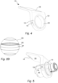
- the outer surface is that of a symmetrical spherical segment, as exemplified Fig. 2B .
- Fig. 2B the meaning of "symmetrical spherical segment" 202 is clarified, and how it constitutes a symmetrical band around a great circle 204 of a sphere 200, making it uniform in every direction. This is a beneficial feature for it to be possible to adjust in every direction. Still, less beneficial shapes are possible.
- the cylindrical inner surface 110 of the holder ring 108 is dimensioned to fit, directly or indirectly, onto the interaction portion 104 of the camera head 100, essentially, it encircles part of the interaction portion 104 of the camera head 100.
- the holder ring 108 is, in the present embodiments not a continuous ring-structure, but rather it is formed in one piece but the two ends 114, 116 of the band forming the ring are not attached to each other. They may, however, loosely interlock, so as to help in maintaining the ring shape. This is in Fig. 2A exemplified by a simplified finger joint 118 that assists in maintaining the shape of the holder ring (so that the ends are not offset).
- the holder ring is formed in one piece, as one continuous annular shape (with whatever inner cross section that matches the cross section of the interaction portion) without any slit.
- the holder ring would be made of a material, or combination of materials, that would allow it to be fitted onto the interaction portion 104 and transfer the clamping power of a holder base 120 (to be described), meaning that it would have some resilience. It would also, however, have to be rigid enough to stay in the grip provided by the holder base so as to maintain its designated orientation.
- One suitable material would be a polymer, such as rubber, yet multiple alternatives are available.
- the disclosed embodiments of the holder ring are believed to be the some of the best ones in terms of simplicity and usability. More complex solutions may be realized as well, such as versions with a hinge functionality, comprising multiple interlocking parts, etc.
- holder ring 108 is shown arranged on the camera head 100.
- Fig. 4 illustrates the holder base 120, with the ring arranged therein.
- the holder base has a receptacle orifice 122 that is dimensioned to, when in a relaxed state, receive the holder ring 108 (and the camera head 100). It also has a tightening functionality, provided by a slit 124 and a screw 126, so that a diameter, or circumference, of the receptacle orifice 122 may be reduced by use of the tightening functionality, i.e., by tightening of the screw 126 and reduction of the slit 124.
- the inner surface of the receptacle orifice 122 has a domed or spherical curvature matching that of the outer surface of the holder ring 108.
- the tightening of the receptacle orifice may be effected in several different ways, one being a screw as used in the present embodiment, other including other types of screws, or manually actuated tightening mechanisms, such as an eccentric actuator, as known in the art.
- the holder base 120 also comprises a slanted surface 128, configured for direct or indirect attachment to a windshield (or other structure) enabling arrangement of the camera head such that it may observe the desired area.
- the angle of the slanted surface 128 in relation to the portion of the holder base 120 that includes the receptacle orifice 122 may vary for different holder bases, and essentially depends on an inclination angle of the windshield in relation to the desired imaging direction.
- FIG. 5 the configuration of Fig. 3 is shown as it is arranged in the holder base of Fig. 4 , the slanted surface of which is adapted to be attached directly or indirectly to a windshield (or to another surface of the vehicle for that matter, such as any of the side windows, a rearward facing window, or a surface nearby these windows).
- FIGS. 6-8 are schematic and illustrates a camera head 100 arranged on a windscreen 132 using the holder ring 108 and holder base 120 according to any embodiment
- Fig. 8 showing the final position of the camera head, with the orientation of Fig. 7 yet the distance to the windscreen of Fig. 6 .
- Figs. 9-11 illustrate another situation where embodiments of the present invention are beneficial.
- Fig. 9 shows the arrangement with a camera head directed horizontally on a slanted windscreen 132, which is a common orientation when using the camera.
- Fig. 10 shows the same arrangement but on a windscreen 132' with a different slanting angle, and it is evident that the same settings will cause an unfortunate orientation of the camera head, as it will be given an upward tilt.
- Fig. 11 illustrates how the situation of Fig. 10 may be improved by utilizing some features of the present invention, firstly the camera head may readily be oriented horizontally, and secondly it may be translated axially to the desired position close to the windscreen 132' (or whatever axial position seems to be fortunate for the situation at hand).
- Figs. 1 and 2A actually illustrates a further feature that may be used in embodiments of the present invention:
- the camera head may be provided with an axial groove, as already mentioned (guiding groove 106), extending axially along the interaction portion of the camera head.
- the holder ring 108 may be provided, at its inner surface, with a protrusion 128, fitting in the axial groove 106. In this way the holder ring 108 will be more securely attached to the camera head 100.
- the inherent structural resilience of the holder ring 108 will maintain the protrusion 128 in the groove 106, and the radial extension of the groove 106 will prevent the holder ring 108 from sliding off the camera head inadvertently.
- a further effect is that the camera head 100 may be extra sensitive in some areas, due to the thickness of the material, or components arranged therein.
- an appropriate axial extension of the groove 106 which may or may not be continuous, it can assist in localizing the ring properly, i.e., preventing the holder ring 108 from being positioned in certain areas.
- the extension of the groove 106 will also in this case ensure that these areas are avoided, and that the pressure of the holder ring 108, from the holder base 120, will not affect the camera head 100 in any adverse manner.
- these guiding means may be provided by other constructional features without departing from the gist of the invention.
- the groove/protrusion may be reversed, so that the groove is present on the holder ring, and vice versa.
- structural blocks could be provided.
- the interaction portion could have circumferential ridges delimiting the travel of the holder ring, whereas the holder ring merely could interact with these circumferential ridges with its edges, without the provision of any further means of interaction.
- the holder ring 108 may have an ornamental groove 130 (see Fig. 3 ), which serves the purpose of communicating to a user where the guiding groove 106 is located, if needed for aiding in the procedure of positioning the camera head correctly in the holder base.
- the holder base could have a physical mark at, e.g., a vertically upper position (in a mounted state), such that alignment of the physical mark and the ornamental groove ensures a particular position of the camera.
- These guiding aids may be formed as tactile elements so that they could be both visually and tactilely observed and on both sides of the elements (the holder ring and the holder base) so as to be available for view and/or feel from both sides.
- a radial extension of the protrusion 128 may be dimensioned in such a way such that the holder ring 108 will not fit into the receptacle orifice if the protrusion 128 is not in the guiding groove 106.
- a further feature of the holder ring 108 is that its lateral edges 136 may be dimensioned to prevent the holder ring 108 to slide out from engagement with the receptacle orifice, while still allowing for a large enough orientation range. The meaning of this is most readily understood from Fig. 5 . If the camera head is oriented out of the position presented there, in one direction or the other, more and more of the holder ring would be exposed outside of the receptacle orifice. At one point too much of the holder ring could be outside of the receptacle orifice, which would be detrimental to the grip. With suitable dimensioning, however, the interaction portion itself will engage an edge of the receptacle orifice, disabling further shift in orientation and prevent disengagement. The thinner the holder ring, the smaller the orientation interval.
- a camera head may have a cylindrical shape, or at least a constant cross-section, along the portion intended for interaction with the holder ring. The longer the portion the greater the possible adjustment amount.
- a product suitable for use in the inventive arrangement is the AXIS F2115-R Varifocal Sensor, which has a circular cross section. Within this product segment, however, square cross sections, with or without rounded corners, are not unusual, in which case the inner surface of the holder ring 108 would have to have a mating cross section, while the outer surface would be as previously described.
- An advantage of the present arrangement is that a relatively simple part in terms of production and availability, the holder ring 108, is the only component that needs to be tailormade for the same arrangement to work with differently shaped camera heads. This simplifies availability and storage. As mentioned before the cross-section of the interaction portion would not have to be perfectly constant.
- the holder base may also comprise a fastening point 132 for, e.g., a cable tie (or corresponding means), which can be used to secure a cable (or cables) carrying signal and power from or to the camera head.
- a connector (or connectors) for such a cable is usually positioned at the back of the camera head, the end opposite to the optics, and a suitable place for the fastening point is therefore the free end of the holder base, on the side facing away from the slanted surface 128.
- the cable tie will act as both a cable guide and a strain relief, protecting the more delicate connectors from excessive loads.
- the fastening point 132 of the present embodiment is simply a groove bridged at the middle and formed in one piece with the holder base, such that the cable tie could be fixed to it in a straightforward manner.
- the material for the holder arrangement may be a polymer, e.g., plastic, such as thermoplastic or a thermosetting plastic, both commonly used for holders of various kinds. If additional strength is needed the polymer may be reinforced with fibers or metal. For further strength, parts of the holder arrangement may be made from metal, such as aluminum. In order to enhance a grip between the holder ring and the adjacent components (the camera head and the holder base) it may be made from a softer polymer, and/or have a surface for increased grip, such as a textured surface or a coating.
- the screw 126 would be made from metal in a conventional manner or from a polymer, and a mating thread may be arranged directly in the holder base 120.
- a hole, or not even that, may provided, and the screw may be a self-tapping screw.
- a nut (not seen) is either molded into the holder base 120 or inserted via a slot (not visible) in order to be able to cooperate with the screw to tighten the receptacle orifice 122.
- the latter may be more complex, having the small dimensions of the product in consideration, yet it may be less prone for thread failure, and should such failure occur, it may be easier to fix.
Landscapes
- Engineering & Computer Science (AREA)
- General Engineering & Computer Science (AREA)
- Mechanical Engineering (AREA)
- Physics & Mathematics (AREA)
- General Physics & Mathematics (AREA)
- Multimedia (AREA)
- Signal Processing (AREA)
- Accessories Of Cameras (AREA)
- Fittings On The Vehicle Exterior For Carrying Loads, And Devices For Holding Or Mounting Articles (AREA)
- Studio Devices (AREA)
Priority Applications (4)
| Application Number | Priority Date | Filing Date | Title |
|---|---|---|---|
| EP23175923.4A EP4470839B1 (en) | 2023-05-30 | 2023-05-30 | A camera arrangement comprising a holder configuration for a camera head and the holder configuration |
| US18/606,248 US12443095B2 (en) | 2023-05-30 | 2024-03-15 | Camera arrangement comprising a holder configuration for a camera head and the holder configuration |
| JP2024081534A JP2024173723A (ja) | 2023-05-30 | 2024-05-20 | カメラヘッドのためのホルダ構成を備えるカメラ機構およびホルダ構成 |
| CN202410639278.7A CN119071624A (zh) | 2023-05-30 | 2024-05-22 | 包括用于摄像头的支架配置件的摄像机装置和支架配置件 |
Applications Claiming Priority (1)
| Application Number | Priority Date | Filing Date | Title |
|---|---|---|---|
| EP23175923.4A EP4470839B1 (en) | 2023-05-30 | 2023-05-30 | A camera arrangement comprising a holder configuration for a camera head and the holder configuration |
Publications (3)
| Publication Number | Publication Date |
|---|---|
| EP4470839A1 EP4470839A1 (en) | 2024-12-04 |
| EP4470839B1 true EP4470839B1 (en) | 2025-04-23 |
| EP4470839C0 EP4470839C0 (en) | 2025-04-23 |
Family
ID=86609894
Family Applications (1)
| Application Number | Title | Priority Date | Filing Date |
|---|---|---|---|
| EP23175923.4A Active EP4470839B1 (en) | 2023-05-30 | 2023-05-30 | A camera arrangement comprising a holder configuration for a camera head and the holder configuration |
Country Status (4)
| Country | Link |
|---|---|
| US (1) | US12443095B2 (enExample) |
| EP (1) | EP4470839B1 (enExample) |
| JP (1) | JP2024173723A (enExample) |
| CN (1) | CN119071624A (enExample) |
Families Citing this family (1)
| Publication number | Priority date | Publication date | Assignee | Title |
|---|---|---|---|---|
| US12413833B2 (en) * | 2023-07-03 | 2025-09-09 | Getac Technology Corporation | Vehicle camera |
Family Cites Families (15)
| Publication number | Priority date | Publication date | Assignee | Title |
|---|---|---|---|---|
| DE10237554B4 (de) | 2002-08-16 | 2007-04-26 | Hella Kgaa Hueck & Co. | Justierbare Kameraanordnung für Kraftfahrzeuge |
| JP4786281B2 (ja) * | 2005-04-20 | 2011-10-05 | 株式会社オートネットワーク技術研究所 | カメラカバー |
| FR2906780B1 (fr) * | 2006-10-06 | 2008-12-26 | Renault Sas | Dispositif electronique de controle dynamique reglable |
| ES2693455T3 (es) * | 2009-03-25 | 2018-12-11 | Magna Electronics Inc. | Montaje de cámara y lente vehicular |
| CN104094148B (zh) * | 2012-02-13 | 2016-03-02 | 富士胶片株式会社 | 监视照相机用透镜装置 |
| WO2015018005A1 (en) | 2013-08-07 | 2015-02-12 | Panasonic Intellectual Property Corporation Of America | Base station apparatus, terminal apparatus, transmitting method, and receiving method |
| JP6744294B2 (ja) * | 2015-03-23 | 2020-08-19 | 株式会社小糸製作所 | 車輌用灯具 |
| US9986136B2 (en) * | 2015-10-30 | 2018-05-29 | Magna Electronics Inc. | Vehicle camera with single point imager fixation to lens holder |
| CN109963748B (zh) * | 2017-10-26 | 2023-04-25 | 法国圣戈班玻璃厂 | 带有集成摄像机模块的车辆附接部件 |
| WO2020010468A1 (en) * | 2018-07-12 | 2020-01-16 | Corechair Incorporated | Resistive support mechanism |
| US11218625B2 (en) * | 2020-05-19 | 2022-01-04 | Motorola Solutions, Inc. | Camera system |
| US12449087B2 (en) * | 2020-08-25 | 2025-10-21 | Axon Enterprise, Inc. | Spherical joint with leveling and panning capability |
| IL305909A (en) * | 2021-04-14 | 2023-11-01 | Omniscient Imaging Inc | Optical, opto-electronic and opto-electro-mechanical systems and a method for using them |
| CN216286113U (zh) * | 2021-09-17 | 2022-04-12 | 深圳市铁头科技有限公司 | 一种相机镜头的拓展机构 |
| US20230111985A1 (en) * | 2021-10-12 | 2023-04-13 | Magna Mirrors Of America, Inc. | Low profile auto-dimming interior rearview mirror assembly |
-
2023
- 2023-05-30 EP EP23175923.4A patent/EP4470839B1/en active Active
-
2024
- 2024-03-15 US US18/606,248 patent/US12443095B2/en active Active
- 2024-05-20 JP JP2024081534A patent/JP2024173723A/ja active Pending
- 2024-05-22 CN CN202410639278.7A patent/CN119071624A/zh active Pending
Also Published As
| Publication number | Publication date |
|---|---|
| CN119071624A (zh) | 2024-12-03 |
| US20240402579A1 (en) | 2024-12-05 |
| EP4470839A1 (en) | 2024-12-04 |
| US12443095B2 (en) | 2025-10-14 |
| JP2024173723A (ja) | 2024-12-12 |
| EP4470839C0 (en) | 2025-04-23 |
Similar Documents
| Publication | Publication Date | Title |
|---|---|---|
| US12443095B2 (en) | Camera arrangement comprising a holder configuration for a camera head and the holder configuration | |
| EP0796780B1 (en) | Interlocking device for opposed racks in an adjustable steering column | |
| US5404182A (en) | Swivel chassis | |
| US6714357B2 (en) | Lens drive system | |
| US10793072B2 (en) | Electric retractable view device for vehicle | |
| US20180111557A1 (en) | Electric retractable view device for vehicle | |
| US20020021254A1 (en) | On-vehicle rod antenna device | |
| US8628257B2 (en) | Image-pickup apparatus, camera grip, and image-pickup system | |
| EP3816705B1 (en) | Mirror device | |
| EP4011707B1 (en) | Fixing assembly | |
| US11218625B2 (en) | Camera system | |
| US6741404B2 (en) | Lens barrel | |
| US20010026401A1 (en) | Lens barrel | |
| EP2255998A1 (en) | Stay device for interior mirror of vehicle | |
| US12207039B2 (en) | Device for expansion and contraction through rotation of rotary shaft and VR headset | |
| EP4174548B1 (en) | External connection device, eyepiece module and handheld apparatus | |
| CN107264411B (zh) | 视觉辨认装置的视觉辨认角度调整机构 | |
| US7175292B2 (en) | Hand adjustable vehicle mirror mechanism | |
| CN107264409B (zh) | 视觉辨认装置的视觉辨认角度调整机构 | |
| JP6555598B2 (ja) | 位置調整装置 | |
| JP2006039051A (ja) | 切換機能を備えたマクロ撮影用レンズ | |
| JPH03212604A (ja) | ねじマウントレンズ鏡筒 | |
| CN107264407B (zh) | 视觉辨认装置的视觉辨认角度调整机构 | |
| JP3539807B2 (ja) | フレキシブルコネクタ | |
| JP3091997B2 (ja) | ねじマウントレンズ鏡筒 |
Legal Events
| Date | Code | Title | Description |
|---|---|---|---|
| PUAI | Public reference made under article 153(3) epc to a published international application that has entered the european phase |
Free format text: ORIGINAL CODE: 0009012 |
|
| STAA | Information on the status of an ep patent application or granted ep patent |
Free format text: STATUS: REQUEST FOR EXAMINATION WAS MADE |
|
| 17P | Request for examination filed |
Effective date: 20240109 |
|
| AK | Designated contracting states |
Kind code of ref document: A1 Designated state(s): AL AT BE BG CH CY CZ DE DK EE ES FI FR GB GR HR HU IE IS IT LI LT LU LV MC ME MK MT NL NO PL PT RO RS SE SI SK SM TR |
|
| GRAP | Despatch of communication of intention to grant a patent |
Free format text: ORIGINAL CODE: EPIDOSNIGR1 |
|
| STAA | Information on the status of an ep patent application or granted ep patent |
Free format text: STATUS: GRANT OF PATENT IS INTENDED |
|
| GRAS | Grant fee paid |
Free format text: ORIGINAL CODE: EPIDOSNIGR3 |
|
| INTG | Intention to grant announced |
Effective date: 20250212 |
|
| GRAA | (expected) grant |
Free format text: ORIGINAL CODE: 0009210 |
|
| STAA | Information on the status of an ep patent application or granted ep patent |
Free format text: STATUS: THE PATENT HAS BEEN GRANTED |
|
| AK | Designated contracting states |
Kind code of ref document: B1 Designated state(s): AL AT BE BG CH CY CZ DE DK EE ES FI FR GB GR HR HU IE IS IT LI LT LU LV MC ME MK MT NL NO PL PT RO RS SE SI SK SM TR |
|
| REG | Reference to a national code |
Ref country code: GB Ref legal event code: FG4D |
|
| REG | Reference to a national code |
Ref country code: CH Ref legal event code: EP |
|
| REG | Reference to a national code |
Ref country code: IE Ref legal event code: FG4D |
|
| U01 | Request for unitary effect filed |
Effective date: 20250423 |
|
| U07 | Unitary effect registered |
Designated state(s): AT BE BG DE DK EE FI FR IT LT LU LV MT NL PT RO SE SI Effective date: 20250429 |
|
| U20 | Renewal fee for the european patent with unitary effect paid |
Year of fee payment: 3 Effective date: 20250516 |
|
| PG25 | Lapsed in a contracting state [announced via postgrant information from national office to epo] |
Ref country code: ES Free format text: LAPSE BECAUSE OF FAILURE TO SUBMIT A TRANSLATION OF THE DESCRIPTION OR TO PAY THE FEE WITHIN THE PRESCRIBED TIME-LIMIT Effective date: 20250423 |
|
| PG25 | Lapsed in a contracting state [announced via postgrant information from national office to epo] |
Ref country code: GR Free format text: LAPSE BECAUSE OF FAILURE TO SUBMIT A TRANSLATION OF THE DESCRIPTION OR TO PAY THE FEE WITHIN THE PRESCRIBED TIME-LIMIT Effective date: 20250724 Ref country code: NO Free format text: LAPSE BECAUSE OF FAILURE TO SUBMIT A TRANSLATION OF THE DESCRIPTION OR TO PAY THE FEE WITHIN THE PRESCRIBED TIME-LIMIT Effective date: 20250723 |
|
| PG25 | Lapsed in a contracting state [announced via postgrant information from national office to epo] |
Ref country code: PL Free format text: LAPSE BECAUSE OF FAILURE TO SUBMIT A TRANSLATION OF THE DESCRIPTION OR TO PAY THE FEE WITHIN THE PRESCRIBED TIME-LIMIT Effective date: 20250423 |
|
| PG25 | Lapsed in a contracting state [announced via postgrant information from national office to epo] |
Ref country code: HR Free format text: LAPSE BECAUSE OF FAILURE TO SUBMIT A TRANSLATION OF THE DESCRIPTION OR TO PAY THE FEE WITHIN THE PRESCRIBED TIME-LIMIT Effective date: 20250423 |
|
| PG25 | Lapsed in a contracting state [announced via postgrant information from national office to epo] |
Ref country code: RS Free format text: LAPSE BECAUSE OF FAILURE TO SUBMIT A TRANSLATION OF THE DESCRIPTION OR TO PAY THE FEE WITHIN THE PRESCRIBED TIME-LIMIT Effective date: 20250723 |
|
| PG25 | Lapsed in a contracting state [announced via postgrant information from national office to epo] |
Ref country code: IS Free format text: LAPSE BECAUSE OF FAILURE TO SUBMIT A TRANSLATION OF THE DESCRIPTION OR TO PAY THE FEE WITHIN THE PRESCRIBED TIME-LIMIT Effective date: 20250823 |