EP4470751A1 - Temperaturregelungsform und verfahren zur herstellung eines harzbehälters - Google Patents
Temperaturregelungsform und verfahren zur herstellung eines harzbehälters Download PDFInfo
- Publication number
- EP4470751A1 EP4470751A1 EP23746986.1A EP23746986A EP4470751A1 EP 4470751 A1 EP4470751 A1 EP 4470751A1 EP 23746986 A EP23746986 A EP 23746986A EP 4470751 A1 EP4470751 A1 EP 4470751A1
- Authority
- EP
- European Patent Office
- Prior art keywords
- preform
- mold
- temperature adjustment
- blow
- temperature
- Prior art date
- Legal status (The legal status is an assumption and is not a legal conclusion. Google has not performed a legal analysis and makes no representation as to the accuracy of the status listed.)
- Pending
Links
- 239000011347 resin Substances 0.000 title claims abstract description 23
- 229920005989 resin Polymers 0.000 title claims abstract description 23
- 238000004519 manufacturing process Methods 0.000 title claims description 11
- 230000001105 regulatory effect Effects 0.000 title 1
- 230000007246 mechanism Effects 0.000 claims abstract description 52
- 238000010438 heat treatment Methods 0.000 claims abstract description 45
- 230000002093 peripheral effect Effects 0.000 claims abstract description 19
- 238000000071 blow moulding Methods 0.000 claims description 49
- 238000001746 injection moulding Methods 0.000 claims description 28
- 238000001816 cooling Methods 0.000 description 38
- 238000002347 injection Methods 0.000 description 26
- 239000007924 injection Substances 0.000 description 26
- 239000000463 material Substances 0.000 description 13
- 230000007423 decrease Effects 0.000 description 10
- 239000010410 layer Substances 0.000 description 5
- 238000000465 moulding Methods 0.000 description 5
- 229920000139 polyethylene terephthalate Polymers 0.000 description 5
- 239000005020 polyethylene terephthalate Substances 0.000 description 5
- -1 polyethylene terephthalate Polymers 0.000 description 3
- 239000003507 refrigerant Substances 0.000 description 3
- 230000002087 whitening effect Effects 0.000 description 3
- 229920000089 Cyclic olefin copolymer Polymers 0.000 description 2
- 239000004698 Polyethylene Substances 0.000 description 2
- 229920000491 Polyphenylsulfone Polymers 0.000 description 2
- 239000004743 Polypropylene Substances 0.000 description 2
- 239000012792 core layer Substances 0.000 description 2
- 238000002425 crystallisation Methods 0.000 description 2
- 230000008025 crystallization Effects 0.000 description 2
- 230000000694 effects Effects 0.000 description 2
- 238000000034 method Methods 0.000 description 2
- 229920003229 poly(methyl methacrylate) Polymers 0.000 description 2
- 229920000573 polyethylene Polymers 0.000 description 2
- 239000004926 polymethyl methacrylate Substances 0.000 description 2
- 229920001155 polypropylene Polymers 0.000 description 2
- 229920012266 Poly(ether sulfone) PES Polymers 0.000 description 1
- 239000004793 Polystyrene Substances 0.000 description 1
- 230000004308 accommodation Effects 0.000 description 1
- NIXOWILDQLNWCW-UHFFFAOYSA-N acrylic acid group Chemical group C(C=C)(=O)O NIXOWILDQLNWCW-UHFFFAOYSA-N 0.000 description 1
- 230000015572 biosynthetic process Effects 0.000 description 1
- 230000008859 change Effects 0.000 description 1
- 238000012986 modification Methods 0.000 description 1
- 230000004048 modification Effects 0.000 description 1
- 230000000149 penetrating effect Effects 0.000 description 1
- 230000000704 physical effect Effects 0.000 description 1
- 239000004417 polycarbonate Substances 0.000 description 1
- 229920000515 polycarbonate Polymers 0.000 description 1
- 229920000728 polyester Polymers 0.000 description 1
- 239000011112 polyethylene naphthalate Substances 0.000 description 1
- 239000004626 polylactic acid Substances 0.000 description 1
- 239000002994 raw material Substances 0.000 description 1
- 239000000243 solution Substances 0.000 description 1
- 239000000126 substance Substances 0.000 description 1
- 239000002344 surface layer Substances 0.000 description 1
- 229920003002 synthetic resin Polymers 0.000 description 1
- 239000000057 synthetic resin Substances 0.000 description 1
- KKEYFWRCBNTPAC-UHFFFAOYSA-L terephthalate(2-) Chemical compound [O-]C(=O)C1=CC=C(C([O-])=O)C=C1 KKEYFWRCBNTPAC-UHFFFAOYSA-L 0.000 description 1
- 229920001169 thermoplastic Polymers 0.000 description 1
- 239000004416 thermosoftening plastic Substances 0.000 description 1
Images

Classifications
-
- B—PERFORMING OPERATIONS; TRANSPORTING
- B29—WORKING OF PLASTICS; WORKING OF SUBSTANCES IN A PLASTIC STATE IN GENERAL
- B29C—SHAPING OR JOINING OF PLASTICS; SHAPING OF MATERIAL IN A PLASTIC STATE, NOT OTHERWISE PROVIDED FOR; AFTER-TREATMENT OF THE SHAPED PRODUCTS, e.g. REPAIRING
- B29C49/00—Blow-moulding, i.e. blowing a preform or parison to a desired shape within a mould; Apparatus therefor
- B29C49/42—Component parts, details or accessories; Auxiliary operations
- B29C49/64—Heating or cooling preforms, parisons or blown articles
- B29C49/6409—Thermal conditioning of preforms
- B29C49/6418—Heating of preforms
- B29C49/64195—Heated by the mould
-
- B—PERFORMING OPERATIONS; TRANSPORTING
- B29—WORKING OF PLASTICS; WORKING OF SUBSTANCES IN A PLASTIC STATE IN GENERAL
- B29B—PREPARATION OR PRETREATMENT OF THE MATERIAL TO BE SHAPED; MAKING GRANULES OR PREFORMS; RECOVERY OF PLASTICS OR OTHER CONSTITUENTS OF WASTE MATERIAL CONTAINING PLASTICS
- B29B13/00—Conditioning or physical treatment of the material to be shaped
- B29B13/02—Conditioning or physical treatment of the material to be shaped by heating
- B29B13/023—Half-products, e.g. films, plates
- B29B13/024—Hollow bodies, e.g. tubes or profiles
-
- B—PERFORMING OPERATIONS; TRANSPORTING
- B29—WORKING OF PLASTICS; WORKING OF SUBSTANCES IN A PLASTIC STATE IN GENERAL
- B29C—SHAPING OR JOINING OF PLASTICS; SHAPING OF MATERIAL IN A PLASTIC STATE, NOT OTHERWISE PROVIDED FOR; AFTER-TREATMENT OF THE SHAPED PRODUCTS, e.g. REPAIRING
- B29C49/00—Blow-moulding, i.e. blowing a preform or parison to a desired shape within a mould; Apparatus therefor
- B29C49/42—Component parts, details or accessories; Auxiliary operations
- B29C49/64—Heating or cooling preforms, parisons or blown articles
- B29C49/6409—Thermal conditioning of preforms
- B29C49/6427—Cooling of preforms
- B29C49/643—Cooling of preforms from the inside
-
- B—PERFORMING OPERATIONS; TRANSPORTING
- B29—WORKING OF PLASTICS; WORKING OF SUBSTANCES IN A PLASTIC STATE IN GENERAL
- B29C—SHAPING OR JOINING OF PLASTICS; SHAPING OF MATERIAL IN A PLASTIC STATE, NOT OTHERWISE PROVIDED FOR; AFTER-TREATMENT OF THE SHAPED PRODUCTS, e.g. REPAIRING
- B29C49/00—Blow-moulding, i.e. blowing a preform or parison to a desired shape within a mould; Apparatus therefor
- B29C49/42—Component parts, details or accessories; Auxiliary operations
- B29C49/64—Heating or cooling preforms, parisons or blown articles
- B29C49/6409—Thermal conditioning of preforms
- B29C49/6427—Cooling of preforms
- B29C49/6435—Cooling of preforms from the outside
-
- B—PERFORMING OPERATIONS; TRANSPORTING
- B29—WORKING OF PLASTICS; WORKING OF SUBSTANCES IN A PLASTIC STATE IN GENERAL
- B29C—SHAPING OR JOINING OF PLASTICS; SHAPING OF MATERIAL IN A PLASTIC STATE, NOT OTHERWISE PROVIDED FOR; AFTER-TREATMENT OF THE SHAPED PRODUCTS, e.g. REPAIRING
- B29C49/00—Blow-moulding, i.e. blowing a preform or parison to a desired shape within a mould; Apparatus therefor
- B29C49/42—Component parts, details or accessories; Auxiliary operations
- B29C49/64—Heating or cooling preforms, parisons or blown articles
- B29C49/6409—Thermal conditioning of preforms
- B29C49/6463—Thermal conditioning of preforms by contact heating or cooling, e.g. mandrels or cores specially adapted for heating or cooling preforms
- B29C49/6467—Thermal conditioning of preforms by contact heating or cooling, e.g. mandrels or cores specially adapted for heating or cooling preforms on the outside
-
- B—PERFORMING OPERATIONS; TRANSPORTING
- B29—WORKING OF PLASTICS; WORKING OF SUBSTANCES IN A PLASTIC STATE IN GENERAL
- B29C—SHAPING OR JOINING OF PLASTICS; SHAPING OF MATERIAL IN A PLASTIC STATE, NOT OTHERWISE PROVIDED FOR; AFTER-TREATMENT OF THE SHAPED PRODUCTS, e.g. REPAIRING
- B29C49/00—Blow-moulding, i.e. blowing a preform or parison to a desired shape within a mould; Apparatus therefor
- B29C49/42—Component parts, details or accessories; Auxiliary operations
- B29C49/64—Heating or cooling preforms, parisons or blown articles
- B29C49/66—Cooling by refrigerant introduced into the blown article
-
- B—PERFORMING OPERATIONS; TRANSPORTING
- B29—WORKING OF PLASTICS; WORKING OF SUBSTANCES IN A PLASTIC STATE IN GENERAL
- B29C—SHAPING OR JOINING OF PLASTICS; SHAPING OF MATERIAL IN A PLASTIC STATE, NOT OTHERWISE PROVIDED FOR; AFTER-TREATMENT OF THE SHAPED PRODUCTS, e.g. REPAIRING
- B29C49/00—Blow-moulding, i.e. blowing a preform or parison to a desired shape within a mould; Apparatus therefor
- B29C49/42—Component parts, details or accessories; Auxiliary operations
- B29C49/64—Heating or cooling preforms, parisons or blown articles
- B29C49/68—Ovens specially adapted for heating preforms or parisons
- B29C49/681—Ovens specially adapted for heating preforms or parisons using a conditioning receptacle, e.g. a cavity, e.g. having heated or cooled regions
-
- B—PERFORMING OPERATIONS; TRANSPORTING
- B29—WORKING OF PLASTICS; WORKING OF SUBSTANCES IN A PLASTIC STATE IN GENERAL
- B29C—SHAPING OR JOINING OF PLASTICS; SHAPING OF MATERIAL IN A PLASTIC STATE, NOT OTHERWISE PROVIDED FOR; AFTER-TREATMENT OF THE SHAPED PRODUCTS, e.g. REPAIRING
- B29C49/00—Blow-moulding, i.e. blowing a preform or parison to a desired shape within a mould; Apparatus therefor
- B29C49/02—Combined blow-moulding and manufacture of the preform or the parison
- B29C2049/023—Combined blow-moulding and manufacture of the preform or the parison using inherent heat of the preform, i.e. 1 step blow moulding
-
- B—PERFORMING OPERATIONS; TRANSPORTING
- B29—WORKING OF PLASTICS; WORKING OF SUBSTANCES IN A PLASTIC STATE IN GENERAL
- B29C—SHAPING OR JOINING OF PLASTICS; SHAPING OF MATERIAL IN A PLASTIC STATE, NOT OTHERWISE PROVIDED FOR; AFTER-TREATMENT OF THE SHAPED PRODUCTS, e.g. REPAIRING
- B29C2949/00—Indexing scheme relating to blow-moulding
- B29C2949/07—Preforms or parisons characterised by their configuration
- B29C2949/0715—Preforms or parisons characterised by their configuration the preform having one end closed
-
- B—PERFORMING OPERATIONS; TRANSPORTING
- B29—WORKING OF PLASTICS; WORKING OF SUBSTANCES IN A PLASTIC STATE IN GENERAL
- B29C—SHAPING OR JOINING OF PLASTICS; SHAPING OF MATERIAL IN A PLASTIC STATE, NOT OTHERWISE PROVIDED FOR; AFTER-TREATMENT OF THE SHAPED PRODUCTS, e.g. REPAIRING
- B29C2949/00—Indexing scheme relating to blow-moulding
- B29C2949/07—Preforms or parisons characterised by their configuration
- B29C2949/076—Preforms or parisons characterised by their configuration characterised by the shape
- B29C2949/0768—Preforms or parisons characterised by their configuration characterised by the shape characterised by the shape of specific parts of preform
- B29C2949/077—Preforms or parisons characterised by their configuration characterised by the shape characterised by the shape of specific parts of preform characterised by the neck
- B29C2949/0771—Wide-mouth
-
- B—PERFORMING OPERATIONS; TRANSPORTING
- B29—WORKING OF PLASTICS; WORKING OF SUBSTANCES IN A PLASTIC STATE IN GENERAL
- B29C—SHAPING OR JOINING OF PLASTICS; SHAPING OF MATERIAL IN A PLASTIC STATE, NOT OTHERWISE PROVIDED FOR; AFTER-TREATMENT OF THE SHAPED PRODUCTS, e.g. REPAIRING
- B29C2949/00—Indexing scheme relating to blow-moulding
- B29C2949/07—Preforms or parisons characterised by their configuration
- B29C2949/076—Preforms or parisons characterised by their configuration characterised by the shape
- B29C2949/0768—Preforms or parisons characterised by their configuration characterised by the shape characterised by the shape of specific parts of preform
- B29C2949/078—Preforms or parisons characterised by their configuration characterised by the shape characterised by the shape of specific parts of preform characterised by the bottom
-
- B—PERFORMING OPERATIONS; TRANSPORTING
- B29—WORKING OF PLASTICS; WORKING OF SUBSTANCES IN A PLASTIC STATE IN GENERAL
- B29C—SHAPING OR JOINING OF PLASTICS; SHAPING OF MATERIAL IN A PLASTIC STATE, NOT OTHERWISE PROVIDED FOR; AFTER-TREATMENT OF THE SHAPED PRODUCTS, e.g. REPAIRING
- B29C2949/00—Indexing scheme relating to blow-moulding
- B29C2949/20—Preforms or parisons whereby a specific part is made of only one component, e.g. only one layer
- B29C2949/22—Preforms or parisons whereby a specific part is made of only one component, e.g. only one layer at neck portion
-
- B—PERFORMING OPERATIONS; TRANSPORTING
- B29—WORKING OF PLASTICS; WORKING OF SUBSTANCES IN A PLASTIC STATE IN GENERAL
- B29C—SHAPING OR JOINING OF PLASTICS; SHAPING OF MATERIAL IN A PLASTIC STATE, NOT OTHERWISE PROVIDED FOR; AFTER-TREATMENT OF THE SHAPED PRODUCTS, e.g. REPAIRING
- B29C2949/00—Indexing scheme relating to blow-moulding
- B29C2949/20—Preforms or parisons whereby a specific part is made of only one component, e.g. only one layer
- B29C2949/24—Preforms or parisons whereby a specific part is made of only one component, e.g. only one layer at flange portion
-
- B—PERFORMING OPERATIONS; TRANSPORTING
- B29—WORKING OF PLASTICS; WORKING OF SUBSTANCES IN A PLASTIC STATE IN GENERAL
- B29C—SHAPING OR JOINING OF PLASTICS; SHAPING OF MATERIAL IN A PLASTIC STATE, NOT OTHERWISE PROVIDED FOR; AFTER-TREATMENT OF THE SHAPED PRODUCTS, e.g. REPAIRING
- B29C2949/00—Indexing scheme relating to blow-moulding
- B29C2949/20—Preforms or parisons whereby a specific part is made of only one component, e.g. only one layer
- B29C2949/26—Preforms or parisons whereby a specific part is made of only one component, e.g. only one layer at body portion
-
- B—PERFORMING OPERATIONS; TRANSPORTING
- B29—WORKING OF PLASTICS; WORKING OF SUBSTANCES IN A PLASTIC STATE IN GENERAL
- B29C—SHAPING OR JOINING OF PLASTICS; SHAPING OF MATERIAL IN A PLASTIC STATE, NOT OTHERWISE PROVIDED FOR; AFTER-TREATMENT OF THE SHAPED PRODUCTS, e.g. REPAIRING
- B29C2949/00—Indexing scheme relating to blow-moulding
- B29C2949/20—Preforms or parisons whereby a specific part is made of only one component, e.g. only one layer
- B29C2949/28—Preforms or parisons whereby a specific part is made of only one component, e.g. only one layer at bottom portion
-
- B—PERFORMING OPERATIONS; TRANSPORTING
- B29—WORKING OF PLASTICS; WORKING OF SUBSTANCES IN A PLASTIC STATE IN GENERAL
- B29C—SHAPING OR JOINING OF PLASTICS; SHAPING OF MATERIAL IN A PLASTIC STATE, NOT OTHERWISE PROVIDED FOR; AFTER-TREATMENT OF THE SHAPED PRODUCTS, e.g. REPAIRING
- B29C2949/00—Indexing scheme relating to blow-moulding
- B29C2949/30—Preforms or parisons made of several components
- B29C2949/3032—Preforms or parisons made of several components having components being injected
-
- B—PERFORMING OPERATIONS; TRANSPORTING
- B29—WORKING OF PLASTICS; WORKING OF SUBSTANCES IN A PLASTIC STATE IN GENERAL
- B29C—SHAPING OR JOINING OF PLASTICS; SHAPING OF MATERIAL IN A PLASTIC STATE, NOT OTHERWISE PROVIDED FOR; AFTER-TREATMENT OF THE SHAPED PRODUCTS, e.g. REPAIRING
- B29C49/00—Blow-moulding, i.e. blowing a preform or parison to a desired shape within a mould; Apparatus therefor
- B29C49/02—Combined blow-moulding and manufacture of the preform or the parison
- B29C49/06—Injection blow-moulding
- B29C49/061—Injection blow-moulding with parison holding means displaceable between injection and blow stations
- B29C49/062—Injection blow-moulding with parison holding means displaceable between injection and blow stations following an arcuate path, e.g. rotary or oscillating-type
-
- B—PERFORMING OPERATIONS; TRANSPORTING
- B29—WORKING OF PLASTICS; WORKING OF SUBSTANCES IN A PLASTIC STATE IN GENERAL
- B29C—SHAPING OR JOINING OF PLASTICS; SHAPING OF MATERIAL IN A PLASTIC STATE, NOT OTHERWISE PROVIDED FOR; AFTER-TREATMENT OF THE SHAPED PRODUCTS, e.g. REPAIRING
- B29C49/00—Blow-moulding, i.e. blowing a preform or parison to a desired shape within a mould; Apparatus therefor
- B29C49/42—Component parts, details or accessories; Auxiliary operations
- B29C49/64—Heating or cooling preforms, parisons or blown articles
- B29C49/6409—Thermal conditioning of preforms
- B29C49/6418—Heating of preforms
-
- B—PERFORMING OPERATIONS; TRANSPORTING
- B29—WORKING OF PLASTICS; WORKING OF SUBSTANCES IN A PLASTIC STATE IN GENERAL
- B29C—SHAPING OR JOINING OF PLASTICS; SHAPING OF MATERIAL IN A PLASTIC STATE, NOT OTHERWISE PROVIDED FOR; AFTER-TREATMENT OF THE SHAPED PRODUCTS, e.g. REPAIRING
- B29C49/00—Blow-moulding, i.e. blowing a preform or parison to a desired shape within a mould; Apparatus therefor
- B29C49/42—Component parts, details or accessories; Auxiliary operations
- B29C49/64—Heating or cooling preforms, parisons or blown articles
- B29C49/6409—Thermal conditioning of preforms
- B29C49/6436—Thermal conditioning of preforms characterised by temperature differential
- B29C49/6445—Thermal conditioning of preforms characterised by temperature differential through the preform length
- B29C49/6452—Thermal conditioning of preforms characterised by temperature differential through the preform length by heating the neck
-
- B—PERFORMING OPERATIONS; TRANSPORTING
- B29—WORKING OF PLASTICS; WORKING OF SUBSTANCES IN A PLASTIC STATE IN GENERAL
- B29C—SHAPING OR JOINING OF PLASTICS; SHAPING OF MATERIAL IN A PLASTIC STATE, NOT OTHERWISE PROVIDED FOR; AFTER-TREATMENT OF THE SHAPED PRODUCTS, e.g. REPAIRING
- B29C49/00—Blow-moulding, i.e. blowing a preform or parison to a desired shape within a mould; Apparatus therefor
- B29C49/42—Component parts, details or accessories; Auxiliary operations
- B29C49/64—Heating or cooling preforms, parisons or blown articles
- B29C49/6409—Thermal conditioning of preforms
- B29C49/6463—Thermal conditioning of preforms by contact heating or cooling, e.g. mandrels or cores specially adapted for heating or cooling preforms
- B29C49/6464—Heating
-
- B—PERFORMING OPERATIONS; TRANSPORTING
- B29—WORKING OF PLASTICS; WORKING OF SUBSTANCES IN A PLASTIC STATE IN GENERAL
- B29C—SHAPING OR JOINING OF PLASTICS; SHAPING OF MATERIAL IN A PLASTIC STATE, NOT OTHERWISE PROVIDED FOR; AFTER-TREATMENT OF THE SHAPED PRODUCTS, e.g. REPAIRING
- B29C49/00—Blow-moulding, i.e. blowing a preform or parison to a desired shape within a mould; Apparatus therefor
- B29C49/42—Component parts, details or accessories; Auxiliary operations
- B29C49/64—Heating or cooling preforms, parisons or blown articles
- B29C49/6409—Thermal conditioning of preforms
- B29C49/6463—Thermal conditioning of preforms by contact heating or cooling, e.g. mandrels or cores specially adapted for heating or cooling preforms
- B29C49/6465—Cooling
-
- B—PERFORMING OPERATIONS; TRANSPORTING
- B29—WORKING OF PLASTICS; WORKING OF SUBSTANCES IN A PLASTIC STATE IN GENERAL
- B29L—INDEXING SCHEME ASSOCIATED WITH SUBCLASS B29C, RELATING TO PARTICULAR ARTICLES
- B29L2031/00—Other particular articles
- B29L2031/712—Containers; Packaging elements or accessories, Packages
- B29L2031/7158—Bottles
Definitions
- the present invention relates to a temperature adjustment mold and a manufacturing apparatus for a resin container.
- a hot parison type blow-molding apparatus has been known as one of manufacturing apparatuses for a resin container.
- the hot parison type blow-molding apparatus is configured to blow-mold a resin container using residual heat from injection molding of a preform, and is advantageous in that it is possible to manufacture a resin container which is diversified and excellent in aesthetic appearance as compared with a cold parison type.
- the injection-molding time of the preform which is the rate-determining stage (for example, the cooling time of the preform in the injection mold performed after injection (after resin filling)), and to additionally cool the preform at high temperature in a temperature adjustment step after injection molding.
- a portion for example, a portion immediately below the neck portion or a bottom portion of the preform
- the amount of heat of the portion is likely to decrease in the temperature adjustment step. That is, the portion strongly cooled in the temperature adjustment step is less likely to stretch during the blow molding due to the decrease in the residual heat, while other regions of the preform (for example, the body portion of the preform) are relatively likely to stretch during the blow molding.
- an object of the present invention is to provide a temperature adjustment mold capable of suppressing local temperature decrease of a preform when air cooling is performed in a temperature adjustment step and improving quality of a blow-molded container.
- the temperature adjustment mold includes: an air introduction member that is inserted into the preform and cools the preform by introducing compressed air from an air supply port into an interior of the preform; a cavity mold that accommodates the preform inside and performs heat exchange in contact with an outer peripheral surface of the preform into which the compressed air has been introduced; and a heating mechanism that heats a first portion of the cavity mold facing the air supply port more than a second portion of the cavity mold located on a downstream side of a flow path of the compressed air than the first portion.
- a temperature adjustment mold capable of suppressing local temperature decrease of a preform when air cooling is performed in a temperature adjustment step and improving quality of a blow-molded container.
- Fig. 1 is a view schematically illustrating a configuration of a blow-molding apparatus 20 according to the present embodiment.
- the blow-molding apparatus 20 according to the present embodiment is a hot parison type (also referred to as a one-stage type) apparatus that blow-molds a container by utilizing residual heat (internal heat amount, heat amount) from injection molding without cooling a preform to room temperature.
- the blow-molding apparatus 20 includes an injection-molding unit 21, a temperature adjustment unit 22, a blow-molding unit 23, a taking-out unit 24, and a conveyance mechanism 26.
- the injection-molding unit 21, the temperature adjustment unit 22, the blow-molding unit 23, and the taking-out unit 24 are disposed at positions rotated by a predetermined angle (for example, 90 degrees) about the conveyance mechanism 26.
- the conveyance mechanism 26 includes a transfer plate 28 (not illustrated in Fig. 1 ) that moves so as to rotate about an axis in a direction perpendicular to the paper surface of Fig. 1 .
- a transfer plate 28 (not illustrated in Fig. 1 ) that moves so as to rotate about an axis in a direction perpendicular to the paper surface of Fig. 1 .
- one or more neck molds 27 (or a neck-mold fixing plate holding one or more neck molds, both of which are not illustrated in Fig. 1 ) for holding a neck portion 11 of a preform 10 or the container are disposed at each predetermined angle (for example, for each molding portion).
- the conveyance mechanism 26 conveys the preform 10 (or the container) having the neck portion 11 held by the neck mold 27 in the order of the injection-molding unit 21, the temperature adjustment unit 22, the blow-molding unit 23, and the taking-out unit 24 by moving the transfer plate 28 by 90 degrees.
- the conveyance mechanism 26 further includes a mold opening mechanism of the neck mold 27 and the like.
- the injection-molding unit 21 includes an injection cavity mold and an injection core mold (which are not illustrated), and manufactures the preform 10 illustrated in Fig. 2 to be described later.
- An injection device 25 that supplies a resin material, which is a raw material of the preform 10, is connected to the injection-molding unit 21.
- the injection cavity mold, the injection core mold, and the neck mold 27 of the conveyance mechanism 26 are closed to form a preform-shaped mold space. Then, by pouring the resin material from the injection device 25 into the mold space having such a preform shape, the preform 10 is manufactured by the injection-molding unit 21.
- the entire shape of the preform 10 is a bottomed cylindrical shape in which one end side is opened and the other end side is closed.
- the preform 10 includes the neck portion 11 formed on one end side and having an opening, a body portion 12 connected to the neck portion 11 and formed in a cylindrical shape, and a bottom portion 13 connected to the body portion 12 and closing the other end side.
- the material of the container and the preform 10 is a thermoplastic synthetic resin, and can be appropriately selected according to the use of the container.
- the material include polyethylene terephthalate (PET), polyethylene naphthalate (PEN), polycyclohexanedimethylene terephthalate (PCTA), Tritan ((registered trademark): co-polyester manufactured by Eastman Chemical Company), polypropylene (PP), polyethylene (PE), polycarbonate (PC), polyethersulfone (PES), polyphenylsulfone (PPSU), polystyrene (PS), cyclic olefin polymer (COP/COC), polymethyl methacrylate: acrylic (PMMA), polylactic acid (PLA), and the like.
- the material of the preform 10 and the container in the present application is preferably PET.
- the neck mold 27 of the conveyance mechanism 26 is not opened, and the preform 10 is held and conveyed as it is.
- the number of the preforms 10 simultaneously molded by the injection-molding unit 21 (that is, the number of containers that can be simultaneously molded by the blow-molding apparatus 20) can be appropriately set.
- the temperature adjustment unit 22 performs temperature equalization and removal of uneven temperature of the preform 10 manufactured by the injection-molding unit 21, and adjusts the temperature of the preform 10 so as to have a temperature suitable for blow molding (for example, about 90°C to 105°C) and a temperature distribution suitable for a container shape to be shaped.
- the temperature adjustment unit 22 also has a function of cooling the preform 10 in a high temperature state after injection molding.
- the temperature of the outer surface of the body portion 12 of the preform 10 is 120°C to 160°C at the time of high temperature mold release in the injection-molding unit 21 or at the time of loading into the temperature adjustment unit 22, and the temperature of the inner portion of the body portion 12 becomes still higher than the temperature of the outer surface of the body portion 12. Since crystallization (whitening) occurs when PET in this temperature zone is slowly cooled, it is necessary to suppress whitening by rapidly cooling the preform 10 by the temperature adjustment unit 22.
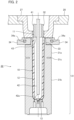
- Fig. 2 is a longitudinal sectional view illustrating a configuration example of the temperature adjustment unit 22.
- the temperature adjustment unit 22 illustrated in Fig. 2 includes a cavity mold (temperature adjustment pot) 31 capable of accommodating the preform 10, and an air introduction member 32 as an example of a temperature adjustment mold.
- the cavity mold 31 is a mold having a temperature adjustment space (cavity surface) capable of accommodating the body portion 12 of the preform 10 manufactured by the injection-molding unit 21.
- the cavity mold 31 illustrated in Fig. 2 may be divided so that the preform 10 can be temperature-adjusted/cooled at different temperatures along the axial direction (vertical direction), and may include, for example, an upper mold 31a and a lower mold 31b.
- the temperature adjustment space of the cavity mold 31 may be the same as or different from the appearance shape of the body portion 12 of the preform 10.
- Examples of the case where the temperature adjustment space of the cavity mold 31 and the appearance shape of the body portion 12 are different from each other include a case where the size (volume) of the temperature adjustment space is larger than the size of the body portion 12 of the preform 10.
- the cavity mold 31 may have a single-stage configuration without being divided.
- the upper mold 31a is a mold that accommodates the upper side of the body portion 12 of the preform 10.
- the lower mold 31b is a mold disposed below the upper mold 31a and accommodating the lower side of the body portion 12 and the bottom portion 13 of the preform 10.
- a heat insulating portion (air heat insulating layer) 31c is provided on the outer peripheral surfaces of the upper mold 31a and the lower mold 31b, and the outer peripheral surface is divided.
- a boundary line is not formed on the inner peripheral surfaces (surfaces on which the temperature adjustment space is formed) of the upper mold 31a and the lower mold 31b and the upper mold 31a and the lower mold 31b are not divided.
- the cavity mold 31 has a single-stage configuration, the cavity mold 31 is a mold in which the body portion 12 and the bottom portion 13 of the preform 10 are accommodated in a single temperature adjustment space.
- a flow path (not illustrated) through which a temperature adjustment medium (refrigerant) flows is formed in an interior of each of the upper mold 31a and the lower mold 31b of the cavity mold 31 having a multi-stage configuration (or the cavity mold 31 having a single-stage configuration). Therefore, the temperature of the upper mold 31a and the lower mold 31b is maintained at a predetermined temperature by the temperature adjustment medium.
- the temperature of the temperature adjustment medium of the cavity mold 31 is not particularly limited, but can be appropriately selected within a range of, for example, 5°C to 90°C, preferably 30°C to 80°C. In the case of the cavity mold 31 having a multi-stage configuration, each stage mold is set to a different temperature, and in the case of the cavity mold 31 having a single-stage configuration, the cavity mold 31 is set to a single temperature.
- the upper end of the upper mold 31a (or the upper end of the cavity mold 31 having a single-stage configuration) has a thin cylindrical stepped portion 33 protruding upward.
- An opening penetrating the upper mold 31a in the vertical direction to accommodate the body portion of the preform 10 is formed on the inner periphery of the stepped portion 33.
- the upper end of the stepped portion 33 faces the bottom surface of the neck mold, and the inner periphery of the stepped portion 33 faces the upper end of the body portion of the preform 10 (position immediately below the neck portion).
- the stepped portion 33 facing the upper end of the body portion of the preform 10 is an example of a first portion of the cavity mold 31.
- the upper mold 31a excluding the stepped portion 33 and the lower mold 31b are an example of the second portion of the cavity mold 31.
- a heating mechanism 34 annularly surrounding a side surface of the stepped portion 33 is attached to an outer peripheral portion of the stepped portion 33.
- the heating mechanism 34 incorporates a heating member (heating element, for example a ring-shaped heater) 34a, and is attached in contact with a side surface of the stepped portion 33.
- the heating mechanism 34 can adjust the temperature independently of the temperature adjustment medium, and the temperature thereof is set to be higher than the temperature of the temperature adjustment medium.
- the temperature of the heating mechanism 34 or the temperature of the stepped portion 33 is set to, for example, about 100°C to 130°C, preferably 100°C to 110°C, and more preferably 100°C to 102°C.
- the heating mechanism 34 is configured to indirectly heat the preform 10 across the stepped portion 33 of the upper mold 31a, the heating mechanism 34 is not exposed on the inner peripheral surface of the upper mold 31a, and the inner peripheral surface of the upper mold 31a is flush.
- the air introduction member 32 has a fitting core 41 and an air flow rod 42, and is inserted into the neck mold 27 and the preform 10.
- the air introduction member 32 is airtightly abutted against the neck portion 11 of the preform 10 in a state of being inserted into the neck mold 27.
- the fitting core 41 and the air flow rod 42 are both hollow cylindrical bodies, and the air flow rod 42 is disposed concentrically inside the fitting core 41.
- the fitting core 41 is in close contact with the inner periphery or the upper end surface of the neck portion 11 when the air introduction member 32 is inserted into an interior of the neck mold 27, and maintains airtightness between the preform 10 and the air introduction member 32.
- the distal end of the fitting core 41 is inserted or abutted to the position of the neck portion 11 of the preform 10. Furthermore, an opening 43 for introducing compressed air (air or gaseous refrigerant) into the preform 10 is formed at the distal end of the fitting core 41.
- the opening 43 illustrated in Fig. 2 is an example of an air supply port.
- a space formed between the fitting core 41 and the air flow rod 42 constitutes a flow path for air supply connected to an air source (not illustrated).
- the distal end of the air flow rod 42 is inserted to the vicinity of the bottom surface of the preform 10.
- An opening 42a for exhausting compressed air from the inside of the preform 10 is formed at the distal end of the air flow rod 42 facing the bottom portion 13 of the preform 10. Therefore, the interior of the air flow rod 42 constitutes a flow path for exhaust.
- the blow-molding unit 23 performs stretch blow-molding on the preform 10 whose temperature has been adjusted by the temperature adjustment unit 22 to manufacture a container.
- the blow-molding unit 23 includes a blow cavity mold which is a pair of split molds corresponding to the shape of the container, a bottom mold, a stretching rod, and an air introduction member (blow core mold, both of which are not illustrated) for blow air supply.
- the blow-molding unit 23 blow-molds the preform 10 while stretching the preform. As a result, the preform 10 is shaped into the shape of the blow cavity mold, and a container can be manufactured.
- the taking-out unit 24 is configured to release the neck portion of the container manufactured by the blow-molding unit 23 from the neck mold 27 and take out the container to the outside of the blow-molding apparatus 20.
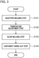
- FIG. 3 is a flowchart showing steps of a blow-molding method.
- Step S101 Injection-molding step
- a resin is injected from the injection device 25 into a preform-shaped mold space formed by the injection cavity mold, the injection core mold, and the neck mold 27 of the conveyance mechanism 26, thereby manufacturing the preform 10.
- the injection mold of the injection-molding unit 21 is opened after completion of injection (filling and pressure holding) of the resin material or after a minimum cooling time provided after completion of injection.
- the time for cooling the resin material (cooling time) after completion of injection of the resin material by the injection-molding unit 21 is preferably 1/2 or less of the time for injecting the resin material (injection time).
- the cooling time can be made shorter than the time for injecting the resin material depending on the weight of the resin material.
- the cooling time is more preferably 2/5 or less, still more preferably 1/4 or less, and particularly preferably 1/5 or less with respect to the injection time of the resin material.
- the skin layer (surface layer in a solidified state) of the preform is thin and the core layer (inner layer in a softened state or a molten state) is formed thick as compared with a case where the preform is sufficiently cooled in the injection mold. That is, in the present embodiment, the preform 10 having a large thermal gradient between the skin layer and the core layer and having high residual heat at a high temperature is formed.
- Step S102 Temperature adjustment step
- cooling and temperature adjustment for bringing the temperature of the preform 10 close to a temperature (blow temperature) suitable for the final blow are performed.
- the temperature of the preform 10 is lowered to the blow temperature, and then the temperature of the preform 10 is maintained at the blow temperature until blow molding is performed.
- whitening beamed due to spherulite formation crystallization that may occur when the preform is slowly cooled is suppressed.
- the preform 10 is accommodated in the cavity mold 31. Subsequently, the air introduction member 32 is inserted into the neck portion 11 of the preform 10 accommodated in the cavity mold 31. At this time, the neck portion 11 of the preform 10 and the fitting core 41 are brought into close contact with each other to enter a state in which airtightness is maintained therebetween.
- cooling blow of the preform 10 is performed.
- the compressed air is introduced to the neck portion 11 side of the preform 10 through the opening 43 of the fitting core 41, and the compressed air is exhausted from the bottom portion 13 side of the preform 10 through the opening 42a of the air flow rod 42.
- preliminary blow may be performed in order to uniformly bring the outer surface of the preform 10 into contact with the temperature adjustment space of the cavity mold 31.
- the compressed air is not exhausted, and the compressed air may be introduced from either the opening 43 of the fitting core 41 or the opening 42a of the air flow rod 42.
- the compressed air flows from the neck portion 11 side toward the bottom portion 13 side in the preform 10, and the preform 10 is cooled from the inside by the compressed air.
- the compressed air since the compressed air is ejected from the opening 43 of the fitting core 41, the compressed air first comes into contact with the upper end of the body portion (immediately below the neck portion) of the preform 10 facing the opening 43 of the fitting core 41.
- the temperature of the compressed air gradually increases toward the bottom portion along the axial direction by heat exchange with the preform 10. Therefore, in the cooling blow, the upper end of the body portion (immediately below the neck portion) of the preform 10 is strongly cooled as compared with the bottom portion of the preform 10 and the lower side of the body portion.
- the preform 10 in the temperature adjustment unit 22 continues to contact the cavity mold 31 maintained at a predetermined temperature by receiving the pressure of the compressed air from the inside, and heat exchange (that is, cooling and temperature adjustment of the preform 10) is also performed between the preform 10 and the cavity mold 31.
- heat exchange that is, cooling and temperature adjustment of the preform 10
- the temperature of the preform 10 is adjusted so as not to become equal to or lower than a temperature suitable for blow molding from the outside, and the uneven temperature generated from injection molding is also reduced.
- the shape of the preform 10 in the temperature adjustment step is maintained by the cavity mold 31 and does not greatly change.
- the heating mechanism 34 set to a temperature higher than the temperature of the temperature adjustment medium is attached to the outer peripheral portion of the stepped portion 33 facing the upper end of the body portion of the preform 10. While the upper end of the body portion of the preform 10 is strongly cooled by the cooling blow, the upper end of the body portion is locally heated from the outside by the heat of the heating mechanism 34 via the stepped portion 33, so that a local temperature decrease at the upper end of the body portion of the preform 10 is suppressed. As a result, the upper end of the body portion of the preform 10 can maintain the residual heat required for the blow molding even when strongly cooled by the cooling blow.
- Step S103 Blow-molding step
- the blow cavity mold is closed, the preform 10 is accommodated in the mold space, and an air introduction member (blow core) for supplying blow air is lowered, so that the air introduction member abuts on the neck portion 11 of the preform 10.
- the stretching rod (longitudinal axis stretching member) is lowered to hold the bottom portion 13 of the preform 10 from the inner surface and the preform 10 is laterally axially stretched by supplying blow air from the air introduction member while performing longitudinal axis stretching as necessary.
- the preform 10 is bulged and shaped so as to be in close contact with the mold space of the blow cavity mold, and is blow-molded into the container.
- the bottom mold stands by at a lower position not in contact with the bottom portion of the preform 10 before closing the blow cavity mold, and quickly rises to the molding position before closing the mold or after closing the mold.
- Step S104 Container taking-out step
- the transfer plate 28 of the conveyance mechanism 26 moves so as to rotate by a predetermined angle, and the container is transported to the taking-out unit 24.
- the neck portion of the container is released from the neck mold 27, and the container is taken out to the outside of the blow-molding apparatus 20.
- the times during which the transfer plate 28 is stopped in the injection-molding unit 21, the temperature adjustment unit 22, the blow-molding unit 23, and the taking-out unit 24 are the same in length.
- the conveyance times of the transfer plate 28 between the respective units are the same in length.
- the preform 10 having no cooling time (or very short cooling time) in the injection mold is accommodated in the cavity mold 31, and the preform 10 is cooled and temperature-adjusted by cooling blow in which compressed air is blown into the preform 10 by the air introduction member 32.
- a heating mechanism 34 is provided in a first portion of the cavity mold 31 facing the air supply port of the compressed air (the stepped portion 33 of the upper mold 31a (or the upper portion of the cavity mold 31 having a single-stage configuration)).
- the portion (upper end of the body portion) of the preform 10 with which the compressed air first comes into contact is strongly cooled at the time of cooling blow, but is locally heated from the outside by the heating mechanism 34 of the cavity mold 31, so that it is possible to maintain the residual heat necessary for blow molding.
- the present embodiment it is possible to suppress a decrease in the temperature of the portion of the preform 10 with which the compressed air comes into contact first at the time of cooling blow in the temperature adjustment unit 22, and thus, it is not necessary to apply a preform having a special shape in which the thickness of the portion (for example, immediately below the neck portion or the upper end of the body portion) is increased in order to leave sufficient residual heat.
- a preform having a special shape there is a restriction that the appearance immediately below the neck portion of the container becomes a step portion (stepped portion).
- the thick portion of the preform is not fully stretched at the time of blow molding, and a lump is formed immediately below the neck portion of the container or the like, and unevenness may occur in the thickness distribution in the vertical direction of the container.
- the heating mechanism 34 of the present embodiment indirectly heats the preform 10 from the outside of the stepped portion 33 without being exposed on the inner peripheral surface of the upper mold 31a (or the cavity mold 31 having a single-stage configuration), there is no parting line by the heating mechanism 34 on the inner peripheral surface of the upper mold 31a (or the cavity mold 31 having a single-stage configuration). Therefore, even if the heating mechanism 34 is provided in the temperature adjustment unit 22, no parting line is formed in the preform 10, and the trace of the cavity mold 31 is less likely to remain in the container after blow molding, so that the quality of the container can be further improved.
- the heat amount of the upper end of the body portion of the preform 10 gradually moves to the neck mold 27 having a relatively low temperature via the neck portion 11, and the temperature decreases during molding. This phenomenon occurs regardless of the direction of the compressed air at the time of cooling blow. Therefore, even in a case where the compressed air is introduced from the air flow rod 42 and exhausted from the opening 43 of the fitting core 41 (even in a case where the compressed air is introduced from the bottom portion 13), the configuration in which the heating mechanism 34 is provided at the upper portion of the cavity mold 31 is effective for suppressing or maintaining the decrease in the residual heat at the upper end of the body portion of the preform 10.
- the present invention is not limited to the above embodiments, and various improvements and design changes may be made without departing from the gist of the present invention.
- the example has been described in which the compressed air is introduced from the neck portion 11 side of the preform 10 and the compressed air is exhausted from the bottom portion 13 side of the preform 10.
- the flow of the compressed air in the cooling blow is not limited to the above.
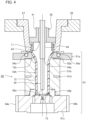
- Fig. 4 is a longitudinal sectional view illustrating another configuration example of the temperature adjustment unit 22.
- the temperature adjustment unit 22 illustrated in Fig. 4 illustrates a configuration example in which compressed air is introduced from the neck portion 11 side and the bottom portion 13 side of a preform 10A.
- the preform 10A in Fig. 4 has a reduced diameter portion (an example of the upper end of the body portion) 12a on the upper end side of the body portion immediately below the neck portion 11, and has a shape in which the inner diameter of the body portion 12 is smaller than the inner diameter of the neck portion 11.
- the same reference numerals are given to elements common to the configuration of Fig. 2 , and redundant description is omitted.
- the cavity mold 51 of the temperature adjustment unit 22 illustrated in Fig. 4 is a mold having a temperature adjustment space having substantially the same shape as the preform 10A manufactured by the injection-molding unit 21.
- the cavity mold 51 is divided in the axial direction of the preform 10A and includes an upper mold 51a, a middle mold 51b, and a lower mold 51c.
- the middle mold 51b is disposed on the lower mold 51c
- the upper mold 51a is disposed on the middle mold 51b.
- the bottom surface of the upper mold 51a and the upper surface of the middle mold 51b are engaged with each other by a spigot joint 55a
- the bottom surface of the middle mold 51b and the upper surface of the lower mold 51c are engaged with each other by a spigot joint 55b.
- the upper mold 51a is a mold that accommodates the reduced diameter portion 12a at the upper end of the body portion of the preform 10A, and the upper surface of the upper mold 51a faces the bottom surface of the neck mold 27.
- the upper mold 51a includes a first heating mechanism 54a, and the first heating mechanism 54a incorporates a first heating member (heating element, ring-shaped heater).
- the middle mold 51b is a mold that accommodates the body portion 12 below the reduced diameter portion 12a in the preform 10A.
- a flow path (not illustrated) through which a temperature adjustment medium (refrigerant) flows is formed in an interior of the middle mold 51b. Therefore, the temperature of the middle mold 51b is maintained at a predetermined temperature by the temperature adjustment medium similarly to the cavity mold 31 of Fig. 2 (for example, 5°C to 90°C, preferably 30°C to 80°C).
- the middle mold 51b may include a plurality of temperature adjustment mechanisms in the axial direction (vertical direction) so that the body portion 12 of the preform can be adjusted or cooled to different temperatures in the axial direction (vertical direction). For example, in Fig.
- a heat insulating portion (air heat insulating layer) 51d is provided on the outer peripheral surface of the middle mold 51b, and the outer peripheral surface of the middle mold 51b is divided.
- no boundary line (parting line) is formed on the inner peripheral surface (surface on which the temperature adjustment space is formed) of the middle mold 51b.
- the lower mold 51c is a mold that accommodates the bottom portion 13 of the preform 10A.
- a second heating mechanism 54b is attached to the lower mold 51c.
- the second heating mechanism 54b incorporates a second heating member (heating element, for example, band heater).
- the upper mold 51a and the lower mold 51c are examples of the first portion of the cavity mold 51. Furthermore, in Fig. 4 , the middle mold 51b is an example of a second portion of the cavity mold 51.
- the first heating mechanism 54a and the second heating mechanism 54b illustrated in Fig. 4 are examples of heating mechanisms, and can adjust the temperature independently of the temperature adjustment medium, and the temperature thereof is set to be higher than the temperature of the temperature adjustment medium.
- the temperature of the first heating mechanism 54a or the upper mold 51a and the temperature of the second heating mechanism 54b or the lower mold 51c are set to, for example, 100°C to 130°C, preferably 100°C to 110°C, and more preferably about 100°C to 102°C.
- the air introduction member 52 is inserted into the neck mold 27 and the preform 10A.
- the air introduction member 52 is different from the air introduction member 32 of Fig. 2 in that a rod outer pipe (second air flow rod) 44 is provided between the inner periphery of the fitting core 41 and the outer periphery of the air flow rod 42.
- the air introduction member 32 illustrated in Fig. 2 may be combined with the cavity mold 51 in Fig. 4 to constitute the temperature adjustment unit 22.
- the air flow rod 42 and the rod outer pipe 44 are concentrically disposed on the inner peripheral side of the fitting core 41. As a result, flow paths of compressed air are formed between the fitting core 41 and the rod outer pipe 44, between the rod outer pipe 44 and the air flow rod 42, and in an interior of the air flow rod 42. Furthermore, when the air introduction member 52 is inserted into the preform 10A, the distal end of the rod outer pipe 44 is located near the boundary between the upper mold 51a and the middle mold 51b (the lower end of the reduced diameter portion 12 of the preform 10A).
- a space between the fitting core 41 and the rod outer pipe 44, and the interior of the air flow rod 42 each constitute a flow path for supplying air
- a space between the rod outer pipe 44 and the air flow rod 42 constitutes a flow path for exhaust.
- the compressed air is introduced to the bottom portion 13 side of the preform 10A through the opening 42a of the air flow rod 42 at the time of cooling blow, and the compressed air is also introduced from the neck portion 11 side of the preform 10A through the opening 43 of the fitting core 41. Then, the compressed air introduced into the preform 10A is exhausted from the opening 44a at the distal end of the rod outer pipe 44.
- the outer surface of the body portion 12 of the preform 10 and the accommodation space (cavity surface) of the preform of the cavity mold 51 may be brought into close contact with each other by performing the preliminary blow before the cooling blow.
- the preform 10A As a result, in the preform 10A, a flow of compressed air from the neck portion 11 side toward the lower end of the reduced diameter portion 12 and a flow of compressed air from the bottom portion 13 side toward the lower end of the reduced diameter portion 12 are generated, and the preform 10A is cooled from the inside by these flows of compressed air.
- the preform 10A in the temperature adjustment unit 22 continues to come into contact with the cavity mold 51 maintained at a predetermined temperature by receiving the pressure of the compressed air from the inside, and heat exchange (that is, cooling and temperature adjustment of the preform 10A) is also performed between the preform 10A and the cavity mold 51.
- the reduced diameter portion 12a and the bottom portion 13 of the preform 10A illustrated in Fig. 4 can maintain the residual heat required for blow molding even when strongly cooled by cooling blow.
- a stepped portion extending in the upward direction of the middle mold 51b may be provided, and a heating mechanism corresponding to the neck portion 11 of the preform 10 may be provided in the stepped portion.
- a stepped portion extending in the downward direction of the middle mold 51b may be provided, and a heating mechanism corresponding to the bottom portion 13 of the preform 10 may be provided in the stepped portion.
- the cavity mold 51 illustrated in Fig. 4 may have a single-stage configuration without being divided into the upper mold 51a, the middle mold 51b, and the lower mold 51c. Then, the first heating mechanism 54a may be provided at the upper portion of the cavity mold 51 (position corresponding to the upper end of the body portion 12 of the preform 10), and the second heating mechanism 54b may be provided at the lower portion of the cavity mold 51 (position corresponding to the bottom portion 13 of the preform 10).
- the first heating member incorporated in the first heating mechanism 54a may be a band heater or an infrared heater in addition to the ring-shaped heater.
Landscapes
- Physics & Mathematics (AREA)
- Thermal Sciences (AREA)
- Engineering & Computer Science (AREA)
- Mechanical Engineering (AREA)
- Manufacturing & Machinery (AREA)
- Blow-Moulding Or Thermoforming Of Plastics Or The Like (AREA)
Applications Claiming Priority (2)
| Application Number | Priority Date | Filing Date | Title |
|---|---|---|---|
| JP2022012160 | 2022-01-28 | ||
| PCT/JP2023/002292 WO2023145775A1 (ja) | 2022-01-28 | 2023-01-25 | 温度調整用金型、樹脂製容器の製造装置 |
Publications (1)
| Publication Number | Publication Date |
|---|---|
| EP4470751A1 true EP4470751A1 (de) | 2024-12-04 |
Family
ID=87471475
Family Applications (1)
| Application Number | Title | Priority Date | Filing Date |
|---|---|---|---|
| EP23746986.1A Pending EP4470751A1 (de) | 2022-01-28 | 2023-01-25 | Temperaturregelungsform und verfahren zur herstellung eines harzbehälters |
Country Status (5)
| Country | Link |
|---|---|
| US (1) | US20250100204A1 (de) |
| EP (1) | EP4470751A1 (de) |
| JP (1) | JPWO2023145775A1 (de) |
| CN (1) | CN118613365A (de) |
| WO (1) | WO2023145775A1 (de) |
Family Cites Families (5)
| Publication number | Priority date | Publication date | Assignee | Title |
|---|---|---|---|---|
| JP2509042B2 (ja) * | 1992-02-21 | 1996-06-19 | 日精エー・エス・ビー機械株式会社 | プリフォ―ムの温調装置 |
| JP3017602B2 (ja) * | 1992-05-27 | 2000-03-13 | 日精エー・エス・ビー機械株式会社 | 再充填可能な合成樹脂製容器 |
| JP3893067B2 (ja) * | 2002-02-19 | 2007-03-14 | 日精エー・エス・ビー機械株式会社 | プリフォームの温調方法 |
| KR102097674B1 (ko) | 2017-10-19 | 2020-04-06 | 닛세이 에이. 에스. 비 기카이 가부시키가이샤 | 수지제 용기의 제조방법, 금형 유닛 및 성형기 |
| KR20230159643A (ko) * | 2019-01-31 | 2023-11-21 | 닛세이 에이. 에스. 비 기카이 가부시키가이샤 | 수지제 용기의 제조장치, 온도조정장치, 수지제 용기의 제조방법 및 온도조정방법 |
-
2023
- 2023-01-25 WO PCT/JP2023/002292 patent/WO2023145775A1/ja not_active Ceased
- 2023-01-25 JP JP2023576948A patent/JPWO2023145775A1/ja active Pending
- 2023-01-25 EP EP23746986.1A patent/EP4470751A1/de active Pending
- 2023-01-25 CN CN202380019006.0A patent/CN118613365A/zh active Pending
- 2023-01-25 US US18/832,688 patent/US20250100204A1/en active Pending
Also Published As
| Publication number | Publication date |
|---|---|
| CN118613365A (zh) | 2024-09-06 |
| WO2023145775A1 (ja) | 2023-08-03 |
| JPWO2023145775A1 (de) | 2023-08-03 |
| US20250100204A1 (en) | 2025-03-27 |
Similar Documents
| Publication | Publication Date | Title |
|---|---|---|
| JP6505344B1 (ja) | 樹脂製の容器の製造方法、金型ユニットおよび成形機 | |
| JP7437475B2 (ja) | 樹脂製容器の製造方法、温度調整用金型およびブロー成形装置 | |
| CN113613862A (zh) | 树脂容器的生产装置和生产方法 | |
| JP7143505B2 (ja) | 首曲がり容器の製造方法 | |
| US11958230B2 (en) | Method for producing resin container and device for producing resin container | |
| EP4299278A1 (de) | Temperaturregelungsform und vorrichtung und verfahren zur herstellung eines harzbehälters | |
| US12208558B2 (en) | Manufacturing method and manufacturing apparatus for delamination container | |
| EP4470751A1 (de) | Temperaturregelungsform und verfahren zur herstellung eines harzbehälters | |
| EP4474132A1 (de) | Temperaturregelungsform sowie vorrichtung und verfahren zur herstellung eines harzbehälters | |
| EP4324620A1 (de) | Herstellungsverfahren und herstellungsvorrichtung für harzbehälter | |
| US20250178266A1 (en) | Temperature adjustment mold, temperature adjustment method, and resin container manufacturing apparatus | |
| US20240017472A1 (en) | Method and apparatus for manufacturing resin container | |
| CN120530008A (zh) | 预成型坯、注塑成型模具、温度调节模具、树脂制容器的制造方法以及树脂制容器的制造装置 | |
| WO2022196658A1 (ja) | 樹脂製容器の製造方法および製造装置 |
Legal Events
| Date | Code | Title | Description |
|---|---|---|---|
| STAA | Information on the status of an ep patent application or granted ep patent |
Free format text: STATUS: THE INTERNATIONAL PUBLICATION HAS BEEN MADE |
|
| PUAI | Public reference made under article 153(3) epc to a published international application that has entered the european phase |
Free format text: ORIGINAL CODE: 0009012 |
|
| STAA | Information on the status of an ep patent application or granted ep patent |
Free format text: STATUS: REQUEST FOR EXAMINATION WAS MADE |
|
| 17P | Request for examination filed |
Effective date: 20240816 |
|
| AK | Designated contracting states |
Kind code of ref document: A1 Designated state(s): AL AT BE BG CH CY CZ DE DK EE ES FI FR GB GR HR HU IE IS IT LI LT LU LV MC ME MK MT NL NO PL PT RO RS SE SI SK SM TR |
|
| DAV | Request for validation of the european patent (deleted) | ||
| DAX | Request for extension of the european patent (deleted) |