EP4470581A2 - Spritzenadapter - Google Patents
Spritzenadapter Download PDFInfo
- Publication number
- EP4470581A2 EP4470581A2 EP24207472.2A EP24207472A EP4470581A2 EP 4470581 A2 EP4470581 A2 EP 4470581A2 EP 24207472 A EP24207472 A EP 24207472A EP 4470581 A2 EP4470581 A2 EP 4470581A2
- Authority
- EP
- European Patent Office
- Prior art keywords
- syringe
- syringe adapter
- connector
- fluid
- cannula
- Prior art date
- Legal status (The legal status is an assumption and is not a legal conclusion. Google has not performed a legal analysis and makes no representation as to the accuracy of the status listed.)
- Pending
Links
Images





Classifications
-
- A—HUMAN NECESSITIES
- A61—MEDICAL OR VETERINARY SCIENCE; HYGIENE
- A61M—DEVICES FOR INTRODUCING MEDIA INTO, OR ONTO, THE BODY; DEVICES FOR TRANSDUCING BODY MEDIA OR FOR TAKING MEDIA FROM THE BODY; DEVICES FOR PRODUCING OR ENDING SLEEP OR STUPOR
- A61M5/00—Devices for bringing media into the body in a subcutaneous, intra-vascular or intramuscular way; Accessories therefor, e.g. filling or cleaning devices, arm-rests
- A61M5/14—Infusion devices, e.g. infusing by gravity; Blood infusion; Accessories therefor
- A61M5/162—Needle sets, i.e. connections by puncture between reservoir and tube ; Connections between reservoir and tube
-
- A—HUMAN NECESSITIES
- A61—MEDICAL OR VETERINARY SCIENCE; HYGIENE
- A61J—CONTAINERS SPECIALLY ADAPTED FOR MEDICAL OR PHARMACEUTICAL PURPOSES; DEVICES OR METHODS SPECIALLY ADAPTED FOR BRINGING PHARMACEUTICAL PRODUCTS INTO PARTICULAR PHYSICAL OR ADMINISTERING FORMS; DEVICES FOR ADMINISTERING FOOD OR MEDICINES ORALLY; BABY COMFORTERS; DEVICES FOR RECEIVING SPITTLE
- A61J1/00—Containers specially adapted for medical or pharmaceutical purposes
- A61J1/14—Details; Accessories therefor
- A61J1/20—Arrangements for transferring or mixing fluids, e.g. from vial to syringe
- A61J1/2003—Accessories used in combination with means for transfer or mixing of fluids, e.g. for activating fluid flow, separating fluids, filtering fluid or venting
- A61J1/2048—Connecting means
- A61J1/2065—Connecting means having aligning and guiding means
-
- A—HUMAN NECESSITIES
- A61—MEDICAL OR VETERINARY SCIENCE; HYGIENE
- A61M—DEVICES FOR INTRODUCING MEDIA INTO, OR ONTO, THE BODY; DEVICES FOR TRANSDUCING BODY MEDIA OR FOR TAKING MEDIA FROM THE BODY; DEVICES FOR PRODUCING OR ENDING SLEEP OR STUPOR
- A61M39/00—Tubes, tube connectors, tube couplings, valves, access sites or the like, specially adapted for medical use
- A61M39/10—Tube connectors; Tube couplings
- A61M39/12—Tube connectors; Tube couplings for joining a flexible tube to a rigid attachment
-
- A—HUMAN NECESSITIES
- A61—MEDICAL OR VETERINARY SCIENCE; HYGIENE
- A61M—DEVICES FOR INTRODUCING MEDIA INTO, OR ONTO, THE BODY; DEVICES FOR TRANSDUCING BODY MEDIA OR FOR TAKING MEDIA FROM THE BODY; DEVICES FOR PRODUCING OR ENDING SLEEP OR STUPOR
- A61M39/00—Tubes, tube connectors, tube couplings, valves, access sites or the like, specially adapted for medical use
- A61M39/22—Valves or arrangement of valves
- A61M39/26—Valves closing automatically on disconnecting the line and opening on reconnection thereof
-
- A—HUMAN NECESSITIES
- A61—MEDICAL OR VETERINARY SCIENCE; HYGIENE
- A61M—DEVICES FOR INTRODUCING MEDIA INTO, OR ONTO, THE BODY; DEVICES FOR TRANSDUCING BODY MEDIA OR FOR TAKING MEDIA FROM THE BODY; DEVICES FOR PRODUCING OR ENDING SLEEP OR STUPOR
- A61M5/00—Devices for bringing media into the body in a subcutaneous, intra-vascular or intramuscular way; Accessories therefor, e.g. filling or cleaning devices, arm-rests
- A61M5/14—Infusion devices, e.g. infusing by gravity; Blood infusion; Accessories therefor
- A61M5/162—Needle sets, i.e. connections by puncture between reservoir and tube ; Connections between reservoir and tube
- A61M2005/1623—Details of air intake
-
- A—HUMAN NECESSITIES
- A61—MEDICAL OR VETERINARY SCIENCE; HYGIENE
- A61M—DEVICES FOR INTRODUCING MEDIA INTO, OR ONTO, THE BODY; DEVICES FOR TRANSDUCING BODY MEDIA OR FOR TAKING MEDIA FROM THE BODY; DEVICES FOR PRODUCING OR ENDING SLEEP OR STUPOR
- A61M39/00—Tubes, tube connectors, tube couplings, valves, access sites or the like, specially adapted for medical use
- A61M39/10—Tube connectors; Tube couplings
- A61M2039/1072—Tube connectors; Tube couplings with a septum present in the connector
-
- A—HUMAN NECESSITIES
- A61—MEDICAL OR VETERINARY SCIENCE; HYGIENE
- A61M—DEVICES FOR INTRODUCING MEDIA INTO, OR ONTO, THE BODY; DEVICES FOR TRANSDUCING BODY MEDIA OR FOR TAKING MEDIA FROM THE BODY; DEVICES FOR PRODUCING OR ENDING SLEEP OR STUPOR
- A61M39/00—Tubes, tube connectors, tube couplings, valves, access sites or the like, specially adapted for medical use
- A61M39/10—Tube connectors; Tube couplings
- A61M2039/1077—Adapters, e.g. couplings adapting a connector to one or several other connectors
-
- A—HUMAN NECESSITIES
- A61—MEDICAL OR VETERINARY SCIENCE; HYGIENE
- A61M—DEVICES FOR INTRODUCING MEDIA INTO, OR ONTO, THE BODY; DEVICES FOR TRANSDUCING BODY MEDIA OR FOR TAKING MEDIA FROM THE BODY; DEVICES FOR PRODUCING OR ENDING SLEEP OR STUPOR
- A61M39/00—Tubes, tube connectors, tube couplings, valves, access sites or the like, specially adapted for medical use
- A61M39/22—Valves or arrangement of valves
- A61M39/26—Valves closing automatically on disconnecting the line and opening on reconnection thereof
- A61M2039/267—Valves closing automatically on disconnecting the line and opening on reconnection thereof having a sealing sleeve around a tubular or solid stem portion of the connector
-
- A—HUMAN NECESSITIES
- A61—MEDICAL OR VETERINARY SCIENCE; HYGIENE
- A61M—DEVICES FOR INTRODUCING MEDIA INTO, OR ONTO, THE BODY; DEVICES FOR TRANSDUCING BODY MEDIA OR FOR TAKING MEDIA FROM THE BODY; DEVICES FOR PRODUCING OR ENDING SLEEP OR STUPOR
- A61M2205/00—General characteristics of the apparatus
- A61M2205/75—General characteristics of the apparatus with filters
-
- A—HUMAN NECESSITIES
- A61—MEDICAL OR VETERINARY SCIENCE; HYGIENE
- A61M—DEVICES FOR INTRODUCING MEDIA INTO, OR ONTO, THE BODY; DEVICES FOR TRANSDUCING BODY MEDIA OR FOR TAKING MEDIA FROM THE BODY; DEVICES FOR PRODUCING OR ENDING SLEEP OR STUPOR
- A61M39/00—Tubes, tube connectors, tube couplings, valves, access sites or the like, specially adapted for medical use
- A61M39/10—Tube connectors; Tube couplings
-
- A—HUMAN NECESSITIES
- A61—MEDICAL OR VETERINARY SCIENCE; HYGIENE
- A61M—DEVICES FOR INTRODUCING MEDIA INTO, OR ONTO, THE BODY; DEVICES FOR TRANSDUCING BODY MEDIA OR FOR TAKING MEDIA FROM THE BODY; DEVICES FOR PRODUCING OR ENDING SLEEP OR STUPOR
- A61M5/00—Devices for bringing media into the body in a subcutaneous, intra-vascular or intramuscular way; Accessories therefor, e.g. filling or cleaning devices, arm-rests
- A61M5/14—Infusion devices, e.g. infusing by gravity; Blood infusion; Accessories therefor
- A61M5/162—Needle sets, i.e. connections by puncture between reservoir and tube ; Connections between reservoir and tube
- A61M5/1626—Needle protectors therefor
-
- A—HUMAN NECESSITIES
- A61—MEDICAL OR VETERINARY SCIENCE; HYGIENE
- A61M—DEVICES FOR INTRODUCING MEDIA INTO, OR ONTO, THE BODY; DEVICES FOR TRANSDUCING BODY MEDIA OR FOR TAKING MEDIA FROM THE BODY; DEVICES FOR PRODUCING OR ENDING SLEEP OR STUPOR
- A61M5/00—Devices for bringing media into the body in a subcutaneous, intra-vascular or intramuscular way; Accessories therefor, e.g. filling or cleaning devices, arm-rests
- A61M5/178—Syringes
Definitions
- the present disclosure relates generally to medical connectors used in fluid transfer applications. More particularly, the present disclosure relates to a syringe adapter for the transfer of fluids in medical settings.
- Medical connectors are widely used to transmit, prepare, and deliver medical fluids.
- the delivery of a medical fluid may include administering the medical fluid intravenously through an intravenous (IV) set from a fluid source such as a syringe.
- IV intravenous
- the fluid-filled syringe includes a rigid structure and cannot collapse when the plunger of the syringe is stationary and the fluid is being pulled from the syringe.
- ambient air needs to be introduced into the syringe to replace the fluid that is being pulled from the syringe.
- a traditional approach to allow air to enter the syringe, as fluid is being pulled from the syringe, includes attaching a device between the syringe and the IV set.
- the device conventionally includes an open female Luer with a cannula that protrudes past the female Luer.
- the cannula is inserted into the syringe, such that a filter at the other end of the cannula provides an air path into the syringe through the cannula.
- a filter at the other end of the cannula provides an air path into the syringe through the cannula.
- An aspect of the present disclosure provides a syringe adapter for coupling with a syringe.
- the syringe adapter comprises a housing and a needle-free connector disposed in the housing.
- a communication member is in slidable engagement with the housing.
- the communication member is slidable, with respect to the housing, between an unactuated state and an actuated state of the syringe adapter.
- a cannula extends from the communication member. In the unactuated, the cannula is retracted within the needle-free connector. In the actuated state, the cannula protrudes through and axially beyond the needle-free connector.
- a piston element is disposed in the needle-free connector.
- the piston element comprises a piston head and a sealable orifice disposed through the piston head, wherein the sealable orifice is in a sealed state when the piston element is in an uncompressed state and is in an opened state when the piston element is in a compressed state.
- the needle-free connector comprises a connection port sealingly flush with the piston head and the sealable orifice when the syringe adapter is uncoupled with the syringe.
- a conduit extends from, and is disposed through, the communication member, wherein the conduit is fluidly separated from the needle-free connector when the syringe adapter is coupled with the syringe and in the unactuated state.
- the conduit is in fluid communication with the needle-free connector when the syringe adapter is coupled with the syringe and in the actuated state.
- a duct extends from, and through, the communication member, wherein the duct fluidly couples the cannula to at least one vent disposed in a filter housing.
- a filter is disposed in the filter housing and a valve is disposed between the filter and the cannula, wherein the valve is configured to allow fluid to flow from the at least one vent through the filter to the cannula and is configured to prevent fluid flow from the cannula to the filter.
- a first fluid path and a second fluid path is provided when the syringe adapter is coupled to the syringe and in the actuated state.
- the first fluid path is configured to provide filtered ambient air into the syringe and the second fluid path is configured to allow fluid from the syringe to flow to an intravenous set coupled to the syringe adapter.
- the first fluid path flows through at least the cannula, the duct, and the at least one vent.
- the second fluid path flows through at least the connection port, the piston element, and the conduit.
- the syringe adapter for coupling a syringe to a fluid system.
- the syringe adapter comprises a female connector.
- a body is in fluid communication with the female connector.
- a male connector is in fluid communication with the female connector and the body.
- the male connector is configured to couple with a medical device.
- a cannula extends axially through the body and out through the female connector.
- a filter housing is in fluid communication with the cannula.
- the filter housing is elevated axially beyond the female connector, wherein a first fluid path is formed through the filter housing and the cannula and a second fluid path is formed through the female connector, the body, and the male connector.
- the filter housing is configured to prevent a filter disposed in the filter housing from contacting fluid in the first fluid path and a closed system is provided when the male connector is uncoupled from the medical device.
- a flexible tubing fluidly couples the filter housing to the cannula.
- the female connector is coupled to the syringe such that the cannula is arranged within a chamber of the syringe.
- a clip is arranged around the syringe and the flexible tubing.
- the clip is configured to secure the flexible tubing to the syringe.
- the medical device is an intravenous set. In further aspects, the medical device is a needle-free connector.
- the syringe adapter comprises a female connector configured to couple with the syringe.
- a body is in fluid communication with the female connector.
- a male connector is in fluid communication with the female connector and the body.
- the male connector is configured to couple with a medical device.
- a chamber extends from, and is in fluid communication with, the body, wherein the chamber is configured to receive fluid from the syringe for subsequent delivery to the medical device.
- a needle-free connector is disposed at, and in fluid communication with, the female connector, wherein the needle-free connector is configured to provide a closed system when the female connector is uncoupled from the syringe.
- a valve is disposed between the female connector and the needle-free connector.
- the chamber is one of a resilient bag, a non-resilient bag, and a collapsible plastic container.
- a phrase such as "an aspect” does not imply that such aspect is essential to the subject technology or that such aspect applies to all configurations of the subject technology.
- a disclosure relating to an aspect may apply to all configurations, or one or more configurations.
- An aspect may provide one or more examples of the disclosure.
- a phrase such as “an aspect” may refer to one or more aspects and vice versa.
- a phrase such as “an embodiment” does not imply that such embodiment is essential to the subject technology or that such embodiment applies to all configurations of the subject technology.
- a disclosure relating to an embodiment may apply to all embodiments, or one or more embodiments.
- An embodiment may provide one or more examples of the disclosure.
- a phrase such "an embodiment” may refer to one or more embodiments and vice versa.
- a phrase such as "a configuration” does not imply that such configuration is essential to the subject technology or that such configuration applies to all configurations of the subject technology.
- a disclosure relating to a configuration may apply to all configurations, or one or more configurations.
- a configuration may provide one or more examples of the disclosure.
- a phrase such as "a configuration” may refer to one or more configurations and vice versa.
- a syringe adapter illustrated in FIGS. 1-17 are configured to couple with a fluid source and provide a closed system, including a closed sealed surface, during a fluid source change from an IV set.
- the syringe adapter in addition to including a closed sealed surface during fluid source changes from the IV set, also includes a cannula in fluid communication with an air vent to allow filtered air to enter the fluid source as fluid is pulled out of the fluid source.
- the syringe adapter is configured to prevent fluid in the fluid source from contacting a filter disposed in the air vent.
- FIG. 1 illustrates an exemplary fluid delivery system 100.
- the fluid delivery system 100 includes a syringe 110, a syringe adapter 112, and an intravenous (IV) set 114.
- the fluid delivery system 100 is an exemplary system in which the syringe adapter 112 is utilized and it is understood that the syringe adapter 112 may be used in other fluid delivery systems.
- the syringe 110 includes a syringe barrel 116, a collar 118 extending radially outwardly from the syringe barrel 116 at one end of the syringe barrel 116, and an end wall 120 formed at an opposite end of the syringe barrel 116.
- the syringe 110 also includes a plunger 122.
- the plunger 122 includes a body 124, a thumb press 126 attached to one end of the body 124, and a stopper 128 (shown in phantom) attached to an opposite end of the body 124.
- the syringe barrel 116 slidably receives the stopper 128 and the body 124 of the plunger 122, such that a syringe chamber 130 is formed within the syringe barrel 116 between the stopper 128 and the end wall 120 of the syringe barrel 116.
- a tip 132 extends axially outwardly from the end wall 120 and is in fluid communication with the syringe chamber 130. In some aspects, the tip 132 is a male Luer connector.
- the syringe adapter 112 is configured to matingly couple with the tip 132.
- the syringe adapter 112 is also configured to matingly couple with a connector 134 of the IV set 114.
- the IV set 114 includes tubing 136 connected to a fitting 138.
- the fitting 138 is a needle-free Luer connector suitable for connection to an infusion device (not shown), such as an IV needle.
- a pumping segment 140 which is a section of tubing suitable for peristaltic manipulation to cause fluid to flow through the tubing and includes alignment fittings 142 to facilitate proper placement of the pumping segment 140 in a pump (not shown), connects segments of the tubing 136.
- the IV set 114 also includes a clamp 144 that can be closed to stop flow through the tubing 136.
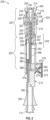
- FIGS. 2-7 illustrate an embodiment of a syringe adapter 200.
- the syringe adapter 200 includes a housing 210 slidably engaged with a communication member 212.
- the housing 210 includes a connection port 214 disposed at one end of the housing 210 and a receiving opening 216 disposed at the other end of the housing 210.
- a female connector 218 forms part of the housing 210 adjacent the connection port 214.
- the female connector is configured to couple with male connectors on various medical device components.
- the female connector is a female Luer connector configured to couple with male Luer connectors on various medical device components.
- the housing 210 also includes a needle-free connector section 220 and a receiving section 222, such that the needle-free connector section 220 is disposed between the connection port 214 and the receiving section 222.
- the receiving section 222 is disposed between the needle-free connector section 220 and the receiving opening 216.
- a needle-free connector 224 is disposed at the needle-free connector section 220 of the housing 210.
- the needle-free connector 224 includes the connection port 214 and the female connector 218.
- the needle-free connector 224 also includes a hollow cylinder 226 disposed within the needle-free connector section 220 of the housing 210.
- the hollow cylinder 226 includes a head 228 at one end and a base 230 at the other end.
- the head 228 of the hollow cylinder 226 is offset axially inwardly from the connection port 214 within the needle-free connector section 220 of the housing 210, such that a bore 232 extends from the connection port 214 to the head 228.
- the connection port 214, the bore 232, and the hollow cylinder 226 are all coaxially aligned.
- the needle-free connector 224 also includes a resiliently deformable piston element 234.
- the resiliently deformable piston element 234 is captured between the connection port 214 and the base 230.
- the piston element 234 includes a piston 236 and a compressible member 238 formed to the piston 236.
- the compressible member 238 includes a plurality of bellows 240.
- the piston 236 includes a piston head 242.
- the piston head 242 includes a sealable orifice 244 disposed therethrough, which is in a sealed state when the piston element 234 is uncompressed and is in an opened state when the piston element 234 in compressed.
- the piston element 234 is uncompressed with the sealable orifice 244 in a sealed state, such that the compressible member 238 is urged against the base 230 while the piston head 242 is located internally to the housing 210 within the bore 232 and is sealingly flush with the surrounding connection port 214 collectively forming a flat, closed, and swabable surface 245.
- the piston element 234 is hollow and includes a piston passage 246, which extends from an exit orifice 247 of the compressible member 238 to the sealable orifice 244.
- the receiving section 222 includes a transition section 248 disposed adjacent to the needle-free connector section 220.
- the transition section 248 includes an annular shoulder 250 axially offset from the base 230, such that a chamber 252 is formed between the base 230 and the shoulder 250.
- the chamber 252 is fluidly coupled to the piston passage 246 via the exit orifice 247 and is coaxially aligned with an aperture 253 disposed in the shoulder 250.
- a channel 254 is disposed in the receiving section 222 and includes a closed end 256, which is disposed adjacent the chamber 252 in the transition section 248.
- the channel 254 includes a transfer passage 258 disposed proximate the closed end 256.
- the channel 254 is fluidly coupled to the chamber 252 via the transfer passage 258.
- the channel 254 extends axially from the closed end 256 through the shoulder 250 to an opened end 260.
- the opened end 260 of the channel 254 terminates within the receiving section 222 and is axially offset from the receiving opening 216 of the housing 210.
- the receiving section 222 also includes a slot 262 that extends axially between the shoulder 250 and the receiving opening 216.
- the slot 262 is configured to slidably guide a neck 264 of the communication member 212 when the syringe adapter 200 transitions from a coupled, unactuated state to a coupled, actuated state.
- the communication member 212 includes the neck 264, a cannula 266, and a conduit 268.
- the neck 264 extends radially from the communication member 212 and terminates at a valve housing 270 that includes an inlet port 272.
- a duct 274 is disposed within the communication member 212 through the neck 264 and the valve housing 270 to the inlet port 272.
- a filter housing 276 is received in fluid communication by the inlet port 272.
- the filter housing 276 surrounds a filter 278 and includes at least one vent 280 configured to allow ambient air to pass through the filter 278.
- a valve 282 is disposed in the valve housing 270 and is configured to allow fluid to flow from the at least one vent 280 through the filter 278 and into the duct 274 and prevent fluid to flow in the opposite direction from the duct 274 to the filter housing 276 ensuring that the filter 278 will not get wetted from fluid possibly in the duct 274.
- the cannula 266 extends axially from, and through, the communication member 212 and is fluidly coupled to the duct 274 at one end and terminates at an opening 267 at an opposite end.
- the conduit 268 is radially offset from the cannula 266 and extends axially from, and through, the communication member 212.
- a crown 284 is disposed at the end of the conduit 268, such that the conduit 268 terminates axially at the crown 284 to fluidly couple with a passage 286.
- a first O-ring 288 is disposed around the crown 284 and a second O-ring 290 is disposed around the conduit 268 between the passage 286 and the communication member 212.
- the conduit 268 Internally of the communication member 212, the conduit 268 is fluidly coupled to an exit port 292.
- a connector 294 is disposed around the exit port 292 and is configured to couple with various medical devices, such as, for example, the connector 134 of the IV set 114.
- the communication member 212 is received, in slidable engagement, by the receiving opening 216 of the housing 210, such that the conduit 268 is slidably received by the channel 254, the cannula 266 is slidably received by a third O-ring 296 disposed in the aperture 253, and the neck 264 is slidably received by the slot 262.
- the third O-ring 296 is configured to seal the cannula 266 with respect to the aperture 253 while allowing the cannula 266 to sealably slide along within the O-ring 296.
- FIG. 3 illustrates the syringe adapter 200 coupled to an IV set, such as, for example, the IV set 114 and in an uncoupled, unactuated state.
- a pre-filled syringe such as, for example, the syringe 110 is in close proximity to, and prepared for coupling with, the syringe adapter 200.
- the cannula 266 is retracted into the needle-free connector 224.
- the piston element 234 is uncompressed, such that the opening 267 of the cannula 266 is arranged in the piston passage 246 within the compressible member 238, the neck 264 rests in the slot 262 proximate the receiving opening 216, and the conduit 268 is arranged in the channel 254 proximate the opened end 260, such that the passage 286 is unaligned with the transfer passage 258 and the conduit 268 is fluidly separated from the needle-free connector 224.
- the sealable orifice 244 is in the sealed state with the piston head 242 sealingly flush with the surrounding connection port 214 forming the flat, closed, and swabable surface 245.
- FIG. 4 illustrates the syringe adapter 200 in a coupled, unactuated state with the syringe 110.
- the male Luer tip 132 is in contact with the piston head 242 and compresses the piston element 234 to move the sealable orifice 244 from the sealed state to the opened state.
- the neck 264 and the conduit 268 are arranged similarly as in the uncoupled, unactuated state, but with the piston element 234 in the compressed state, the opening 267 of the cannula 266 is now arranged in the piston passage 246 within the piston 236 instead of the compressible member 238.
- the passage 286 and the transfer passage 258 are unaligned in this state and with the first O-ring 288 in sealing contact with the channel 254, ambient air from the filter housing 276 is prevented from flowing through the channel 254 and past the first O-ring 288 to the IV set 114 via the exit port 292.
- This is especially beneficial in scenarios where the IV set 114 includes the pumping segment 140 inserted into a pump and the pump is turned on before the syringe adapter 200 transitions to the coupled, actuated state.
- the valve 282 prevents fluid from the syringe chamber 130 from flowing to the filter 278.
- the syringe adapter 200 In order to allow fluid to flow from the syringe 110 to the IV set 114, the syringe adapter 200 is required to enter the coupled, actuated state, as illustrated in FIG. 5 .
- the housing 210 For the syringe adapter 200 to enter the coupled, actuated state from the coupled, unactuated state, the housing 210 is slid axially around, and locked to, the communication member 212, such that the cannula 266 is protruded from the needle-free connector 224.
- the neck 264 is arranged in the slot 262 proximate the shoulder 250, the communication member 212 abuts the shoulder 250, the conduit 268 is arranged in the channel 254 with the crown 284 abutting the closed end 256 of the channel 254, and the opening 267 of the cannula 266 is arranged in the syringe 110 axially beyond the end wall 120 at a location that is axially beyond a fluid intake at the needle-free connector 224.
- the crown 284 abutting the closed end 256 of the channel 254
- the passage 286 aligns with the transfer passage 258 to fluidly couple the conduit 268 with the chamber 252 and to the needle-free connector 224.
- the second O-ring 290 seals the conduit 268 with the channel 254 and prevents fluid entering the passage 286 from traveling axially past the second O-ring 290 into the channel 254.
- a first fluid path is formed, at least, through the at least one vent 280, the duct 274, and the cannula 266.
- ambient air enters the first fluid path through the at least one vent 280, the filter 278, the valve 282, the duct 274, the cannula 266, and the opening 267 of the cannula 266 into the syringe chamber 130.
- the first fluid path provides filtered ambient air into the syringe chamber 130, a reservoir is created in the syringe chamber 130 allowing the fluid in the syringe chamber 130 to vent or flow through a second fluid path without requiring the plunger 122 to be depressed.
- the second fluid path is formed, at least, through the connection port 214, the conduit 268, and the exit port 294.
- fluid from the syringe chamber 130 flows through the tip 132 and the around the cannula 266 following the second fluid path at the connection port 214 through the bore 232, the sealed orifice 244 in the opened state, the piston passage 246, the exit orifice 247, the chamber 252, the transfer passage 258, the passage 286, the conduit 268, and the exit port 294 to the IV set 114.
- the fluid in the syringe chamber 130 flows through the second fluid path by gravity.
- a bag pump (not shown) is utilized, such that the pumping segment 140 is inserted into the bag pump to regulate peristaltic manipulation causing the fluid to flow through the second fluid path.
- the syringe adapter 200 can be utilized with the bag pump, such as a large volume pump (LVP), in such a manner that a depleted IV bag can be replaced with the syringe 110 and syringe adapter 200 without necessitating a separate syringe pump.
- LVP large volume pump
- the syringe adapter 200 is transitioned from the coupled, actuated state to the coupled, unactuated state by sliding the housing 210 axially with respect to the communication member 212, and then transitioned from the coupled, unactuated state to the uncoupled, unactuated state by uncoupling the syringe 110 from the syringe adapter 200.
- the sealable orifice 244 In the uncoupled, unactuated state, the sealable orifice 244 is in the sealed state and the piston head 242 is located internally to the housing 210 within the bore 232 and is sealingly flush with the surround connection port 214, such that closed, flat surface 245 can be swabbed before coupling a replacement syringe to the syringe adapter 200.
- FIGS. 8-11 illustrate another embodiment of a syringe adapter 800. Similar to the syringe adapter 200, the syringe adapter 800 is couplable to a fluid source and includes a first fluid path that allows filtered air to enter the fluid source as fluid is pulled out of the fluid source through a second fluid path while preventing a filter in the first fluid path from exposure to fluid in the fluid source. The syringe adapter 800 also provides a closed system during a fluid source change from an IV set.
- the syringe adapter 800 includes a female connector 810, a male connector 812, and a body 814 fluidly coupling the female connector 810 to the male connector 812.
- the female connector 810 is a female Luer connector
- the male connector 812 is a male Luer connector.
- the syringe adapter 800 also includes a passage 816 extending radially through the body 814.
- a filter housing 818 is fluidly coupled to an end of the passage 816 that is exterior to the body 814.
- the filter housing 818 terminates at a vent 820, which is also in fluid communication with the passage 816.
- a filter 822 is disposed in the filter housing 818 and filters ambient air entering the vent 820.
- a valve (not shown) is disposed in the filter housing 818 between the filter 822 and the passage 816 and is configured to allow ambient air to flow from the vent 820 to the passage 816 via the filter 822 and to prevent fluid from flowing from the passage 816 to the filter 822.
- the filter housing 818 is elevated with respect to the female connector 810 and is angled with respect to the passage 816 and extends axially away from the male connector 812 and axially beyond the female connector 810, such that the filter housing 818 and the filter 822 is arranged above (e.g., axially beyond) the female connector 810.
- the syringe adapter 800 also includes a cannula 824 fluidly coupled to the passage 816 at an end of the passage 816 that is disposed within the body 814.
- the cannula 824 extends axially within the body 814 and out through the female connector 810.
- An opening 826 of the cannula 824 is arranged axially offset from, and exterior to, the female connector 810.
- a first fluid path is formed through, at least, the cannula 824, the passage 816, and the vent 820.
- a second fluid path is formed through, at least, the female connector 810, the body 814, and the male connector 812.
- the female connector 810 is configured to couple with a male connector of a fluid source, such as, for example, the syringe 110.
- the male connector 812 is configured to couple with a female connector of a medical device, such as, for example, the IV set 114.
- the syringe adapter 800 is coupled to the IV set 114 and the syringe 110 is coupled to the syringe adapter 800, such that the opening 826 of the cannula 824 is arranged within the syringe chamber 130 of the syringe 110.
- the filter housing 818 is angled with respect to the passage 816 and extends axially away from the male connector 812 and axially beyond the female connector 810, the filter 822 is prevented from coming in contact with the fluid from the syringe chamber 130, if the plunger 122 is accidentally depressed, due to the arrangement of filter housing 818 with respect to fluid intake at the second fluid path.
- the fluid in the syringe chamber 130 flows through the second fluid path by gravity.
- a bag pump (not shown) is utilized, such that the pumping segment 140 is inserted into the bag pump to regulate peristaltic manipulation causing the fluid to flow through the second fluid path.
- the syringe adapter 800 When the syringe 110 is ready to be replaced the syringe adapter 800, while still coupled to the syringe 110, is uncoupled from the IV set 114 providing a closed system during the syringe change. Both the syringe 110 and the syringe adapter 800 can be disposed and a new syringe adapter 800 can be coupled to the IV set 114 so that a replacement syringe can be coupled to the syringe adapter 800 without having to break the closed system.
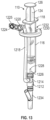
- FIGS. 12-15 illustrate another embodiment of a syringe adapter 1200. Similar to the syringe adapter 200, the syringe adapter 1200 is couplable to a fluid source and also includes a first fluid path that allows filtered air to enter the fluid source as fluid is pulled out of the fluid source through a second fluid path while preventing a filter in the first fluid path from exposure to fluid in the fluid source. The syringe adapter 1200 also provides a closed system during a fluid source change from an IV set.
- the syringe adapter 1200 includes a female connector 1210, a male connector 1212, and a body 1214 fluidly coupling the female connector 1210 to the male connector 1212.
- the female connector 1210 is a female Luer connector
- the male connector 1212 is a male Luer connector.
- the syringe adapter 1200 includes a passage 1216 extending radially through the body 1214.
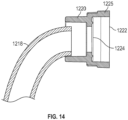
- a flexible tubing 1218 is fluidly coupled to an end of the passage 1216 that is exterior to the body 1214.
- the flexible tubing 1218 is also fluidly coupled to a filter housing 1220.
- the filter housing 1220 terminates at a vent 1222, which is also in fluid communication with the flexible tubing 1218.
- a filter 1224 is disposed in the filter housing 1220 between the vent 1222 and the flexible tubing 1218 and filters ambient air entering the vent 1222 to the flexible tubing 1218.
- a cap 1225 is hingedly coupled to the filter housing 1220 to secure the filter 1224 within the filter housing 1220 and facilitate in replacement of the filter 1224.
- the syringe adapter 1200 also include a cannula 1226 fluidly coupled to the passage 1216 at an end of the passage 1216 that is disposed within the body 1214.
- the cannula 1226 extends axially within the body 1214 and out through the female connector 1210.
- An opening 1228 of the cannula 1226 is arranged axially offset from, and exterior to, the female connector 1210.
- a first fluid path is formed through, at least, the cannula 1226, the passage 1216, the flexible tubing 1218, and the vent 1222.
- a second fluid path is formed through, at least, the female connector 1210, the body 1214, and the male connector 1212.
- the syringe adapter 1200 is configured to couple with a fluid source, such as, for example, the syringe 110 and includes a clip 1230 for securing the flexible tubing 1218 in place against the syringe barrel 116 of the syringe 110 when the syringe adapter 1200 is coupled to the syringe 110.
- the clip 1230 includes an annular shape with a slit 1232 to facilitate the placement of the clip 1230 around the syringe barrel 116 and the flexible tubing 1218 for holding the flexible tubing 1218 to the syringe barrel 116.
- the flexible tubing 1218 is arranged axially along the syringe barrel 116, such that the clip 1230 is arranged around the syringe barrel 116 with the filter housing 1220 proximate the collar 118 and with the flexible tubing 1218 secured against the syringe barrel 116 and arranged between the clip 1230 and the syringe barrel 116.
- the filter housing 1220 With the filter housing 1220 arranged proximate the collar 118 and above (e.g., axially beyond) a level of any fluid in the syringe chamber 130, the filter housing is elevated with respect to the female connector 1210 and the filter 1224 is prevented from contact with fluid from the syringe chamber 130 if the plunger 122 is accidentally depressed.
- the female connector 1210 is configured to couple with a male connector of a fluid source, such as, for example, the syringe 110.
- the male connector 1212 is configured to couple with a female connector of a medical device, such as, for example, a needle-free connector 1234, which is, in turn, coupled to the IV set 114, for example.
- the syringe adapter 1200 is coupled to the IV set 114 via the needle-free connector 1234 and the syringe 110 is coupled to the syringe adapter 1200, such that the opening 1228 of the cannula 1226 is arranged within the syringe chamber 130 of the syringe 110.
- the first fluid path provides filter ambient air into the syringe chamber 130
- a reservoir is created in the syringe chamber 130 allowing the fluid in the syringe chamber 130 to vent through the second fluid path without requiring the plunger 122 to be depressed.
- the filter 1224 is prevented from contact with fluid from the syringe chamber 130 in scenarios when the plunger 122 is accidentally depressed because the filter housing 1220 and the filter 1224 is raised above the level of any fluid in the syringe chamber 130.
- the fluid in the syringe chamber 130 flows through the second fluid path by gravity.
- a bag pump (not shown) is utilized, such that the pumping segment 140 is inserted into the bag pump to regulate peristaltic manipulation causing the fluid to flow through the second fluid path.
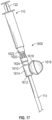
- FIGS. 16 and 17 illustrate another embodiment syringe adapter 1600.
- the syringe adapter 1600 also provides a closed system during a fluid source change from an IV set.
- the syringe adapter 1600 includes a female connector 1610, a male connector 1612, and a body 1614 fluidly coupling the female connector 1610 to the male connector 1612.
- the female connector 1610 is a female Luer connector
- the male connector 1612 is a male Luer connector.
- the syringe adapter 1600 includes a chamber 1616 fluidly coupled to, and extending outwardly from, the body 1614.
- the chamber 1616 can be, for example, a resilient bag, a non-resilient bag, or a collapsible plastic container.
- the syringe adapter 1600 includes a holder 1618 for supporting the chamber 1616.
- the syringe adapter 1600 also includes a needle-free connector 1620 disposed at, and in fluid communication with, the female connector 1610.
- the needle-free connector 1620 integrally formed with the female connector 1610.
- the needle-free connector 1620 includes a male connector, which is couplable to the female connector 1610.
- the needle-free connector 1620 also includes a female fitting 1622, which is couplable to a male connector of a medical device, such as the syringe 110.
- a valve 1624 (shown in phantom), such as a check valve, for example, is disposed between the needle-free connector 1620 and the female connector 1610. The valve 1624 is configured to allow fluid flow from the needle-free connector 1620 to the female connector 1610 and prevent fluid flow from the female connector 1610 to the needle-free connector 1620.
- the male connector 1612 of the syringe adapter 1600 is coupled to a medical device, such as, for example, a pump fitting or the connector 134 of the IV set 114.
- a medical device such as, for example, a pump fitting or the connector 134 of the IV set 114.
- the syringe adapter 1600 is then coupled to the needle-free connector 1620 of the syringe adapter 1600.
- the plunger 122 of the syringe 110 is depressed to push the fluid in the syringe 110 through the needle-free connector 1620, the female connector 1610, and into the chamber 1616.
- the chamber 1616 is a resilient elastomeric bag
- the chamber 1616 is unfilled with fluid, as illustrated in FIG.
- the syringe 110 can be uncoupled from the syringe adapter 1600 to provide a closed system via the needle-free connector 1620. Fluid in the chamber 1616 can then subsequently flow through the male connector 1612 to the IV set 114 either by gravity or via a pump (not shown) as atmospheric pressure allows the fluid in the chamber 1616 to flow without resistance.
- the needle-free connector 1620 can be swabbed and a new syringe coupled to the needle-free connector 1620 to fill the chamber 1616 as described above.
- the phrase "at least one of' preceding a series of items, with the term “and” or “or” to separate any of the items, modifies the list as a whole, rather than each member of the list (i.e., each item).
- the phrase "at least one of” does not require selection of at least one of each item listed; rather, the phrase allows a meaning that includes at least one of any one of the items, and/or at least one of any combination of the items, and/or at least one of each of the items.
- phrases “at least one of A, B, and C” or “at least one of A, B, or C” each refer to only A, only B, or only C; any combination of A, B, and C; and/or at least one of each of A, B, and C.
Landscapes
- Health & Medical Sciences (AREA)
- Heart & Thoracic Surgery (AREA)
- Life Sciences & Earth Sciences (AREA)
- Veterinary Medicine (AREA)
- Public Health (AREA)
- General Health & Medical Sciences (AREA)
- Animal Behavior & Ethology (AREA)
- Anesthesiology (AREA)
- Hematology (AREA)
- Biomedical Technology (AREA)
- Engineering & Computer Science (AREA)
- Vascular Medicine (AREA)
- Pulmonology (AREA)
- Physics & Mathematics (AREA)
- Fluid Mechanics (AREA)
- Pharmacology & Pharmacy (AREA)
- Infusion, Injection, And Reservoir Apparatuses (AREA)
Applications Claiming Priority (3)
| Application Number | Priority Date | Filing Date | Title |
|---|---|---|---|
| US16/158,179 US11285261B2 (en) | 2018-10-11 | 2018-10-11 | Syringe adapter |
| EP19791015.1A EP3866886B1 (de) | 2018-10-11 | 2019-10-01 | Spritzenadapter |
| PCT/US2019/054098 WO2020076561A1 (en) | 2018-10-11 | 2019-10-01 | Syringe adapter |
Related Parent Applications (2)
| Application Number | Title | Priority Date | Filing Date |
|---|---|---|---|
| EP19791015.1A Division EP3866886B1 (de) | 2018-10-11 | 2019-10-01 | Spritzenadapter |
| EP19791015.1A Division-Into EP3866886B1 (de) | 2018-10-11 | 2019-10-01 | Spritzenadapter |
Publications (2)
| Publication Number | Publication Date |
|---|---|
| EP4470581A2 true EP4470581A2 (de) | 2024-12-04 |
| EP4470581A3 EP4470581A3 (de) | 2025-03-05 |
Family
ID=68296744
Family Applications (2)
| Application Number | Title | Priority Date | Filing Date |
|---|---|---|---|
| EP19791015.1A Active EP3866886B1 (de) | 2018-10-11 | 2019-10-01 | Spritzenadapter |
| EP24207472.2A Pending EP4470581A3 (de) | 2018-10-11 | 2019-10-01 | Spritzenadapter |
Family Applications Before (1)
| Application Number | Title | Priority Date | Filing Date |
|---|---|---|---|
| EP19791015.1A Active EP3866886B1 (de) | 2018-10-11 | 2019-10-01 | Spritzenadapter |
Country Status (7)
| Country | Link |
|---|---|
| US (4) | US11285261B2 (de) |
| EP (2) | EP3866886B1 (de) |
| JP (3) | JP7376584B2 (de) |
| CN (3) | CN113164679B (de) |
| AU (1) | AU2019357891B2 (de) |
| CA (1) | CA3115759A1 (de) |
| WO (1) | WO2020076561A1 (de) |
Families Citing this family (5)
| Publication number | Priority date | Publication date | Assignee | Title |
|---|---|---|---|---|
| US11285261B2 (en) | 2018-10-11 | 2022-03-29 | Carefusion 303, Inc. | Syringe adapter |
| DE102020210629A1 (de) | 2020-08-20 | 2022-02-24 | B. Braun Melsungen Aktiengesellschaft | Filtersystem für ein geschlossenes Fluidtransfersystem mit Druckausgleich |
| US20240424226A1 (en) * | 2023-06-21 | 2024-12-26 | Carefusion 303, Inc. | Vented syringe adapter with bulb |
| WO2025250944A1 (en) * | 2024-05-31 | 2025-12-04 | Boston Scientific Scimed, Inc. | Catheter connection manifold bypass accessory device |
| WO2026077455A1 (zh) * | 2024-10-11 | 2026-04-16 | 成都弘基生物科技有限公司 | 一种注射器适配器、注射组件及使用方法 |
Family Cites Families (15)
| Publication number | Priority date | Publication date | Assignee | Title |
|---|---|---|---|---|
| US4623343A (en) | 1984-03-19 | 1986-11-18 | Quest Medical, Inc. | Parenteral fluid administration apparatus and method |
| JP3499317B2 (ja) * | 1995-01-24 | 2004-02-23 | オーベクス株式会社 | 液体供給装置 |
| US7789864B2 (en) * | 1996-11-18 | 2010-09-07 | Nypro Inc. | Luer-activated valve |
| US7645274B2 (en) * | 2004-12-10 | 2010-01-12 | Cardinal Health 303, Inc. | Self-sealing male luer connector with multiple seats |
| US7896859B2 (en) * | 2005-10-20 | 2011-03-01 | Tyco Healthcare Group Lp | Enteral feeding set |
| US8454579B2 (en) * | 2009-03-25 | 2013-06-04 | Icu Medical, Inc. | Medical connector with automatic valves and volume regulator |
| ES2493515T3 (es) * | 2010-05-06 | 2014-09-11 | Icu Medical, Inc. | Conector médico con conexión tipo Luer obturable |
| US20150032063A1 (en) * | 2011-05-13 | 2015-01-29 | Gale Harrison Thorne | Components and devices for closed medical system operation |
| CN104955507B (zh) * | 2013-09-06 | 2019-12-31 | 托马斯·J·肖 | 具有滑动前端附接部及可回缩针的医疗装置 |
| WO2016019138A1 (en) | 2014-07-30 | 2016-02-04 | Covidien Lp | Vented connector for feeding syringe |
| US9682189B2 (en) | 2015-02-27 | 2017-06-20 | Carefusion 2200, Inc. | Smart check valve |
| AU2016276956B2 (en) * | 2015-06-12 | 2018-08-09 | Becton Dickinson and Company Limited | Syringe adapter with spinning connector |
| ES2792025T3 (es) * | 2015-10-28 | 2020-11-06 | Carefusion 303 Inc | Dispositivo de acceso IV cerrado con puerto y conector sin aguja |
| JP6962923B2 (ja) * | 2016-09-26 | 2021-11-05 | テルモ株式会社 | オスコネクタ、医療器具及び接続方法 |
| US11285261B2 (en) * | 2018-10-11 | 2022-03-29 | Carefusion 303, Inc. | Syringe adapter |
-
2018
- 2018-10-11 US US16/158,179 patent/US11285261B2/en active Active
-
2019
- 2019-10-01 JP JP2021519706A patent/JP7376584B2/ja active Active
- 2019-10-01 WO PCT/US2019/054098 patent/WO2020076561A1/en not_active Ceased
- 2019-10-01 CN CN201980081464.0A patent/CN113164679B/zh active Active
- 2019-10-01 EP EP19791015.1A patent/EP3866886B1/de active Active
- 2019-10-01 CA CA3115759A patent/CA3115759A1/en active Pending
- 2019-10-01 AU AU2019357891A patent/AU2019357891B2/en active Active
- 2019-10-01 EP EP24207472.2A patent/EP4470581A3/de active Pending
- 2019-10-01 CN CN202310280712.2A patent/CN116271325B/zh active Active
- 2019-10-01 CN CN202511649862.1A patent/CN121177613A/zh active Pending
-
2022
- 2022-02-17 US US17/674,639 patent/US11992654B2/en active Active
-
2023
- 2023-10-26 JP JP2023183704A patent/JP7611342B2/ja active Active
-
2024
- 2024-04-08 US US18/629,246 patent/US12397107B2/en active Active
- 2024-12-23 JP JP2024225926A patent/JP7813863B2/ja active Active
-
2025
- 2025-07-17 US US19/272,371 patent/US20250339613A1/en active Pending
Also Published As
| Publication number | Publication date |
|---|---|
| JP7376584B2 (ja) | 2023-11-08 |
| JP7611342B2 (ja) | 2025-01-09 |
| US20220168503A1 (en) | 2022-06-02 |
| JP2025028359A (ja) | 2025-02-28 |
| US11992654B2 (en) | 2024-05-28 |
| EP3866886C0 (de) | 2024-12-18 |
| CN113164679A (zh) | 2021-07-23 |
| JP2022504603A (ja) | 2022-01-13 |
| EP4470581A3 (de) | 2025-03-05 |
| JP2023175035A (ja) | 2023-12-08 |
| AU2019357891B2 (en) | 2024-06-27 |
| EP3866886A1 (de) | 2021-08-25 |
| US20250339613A1 (en) | 2025-11-06 |
| CN116271325A (zh) | 2023-06-23 |
| US11285261B2 (en) | 2022-03-29 |
| JP7813863B2 (ja) | 2026-02-13 |
| CN121177613A (zh) | 2025-12-23 |
| EP3866886B1 (de) | 2024-12-18 |
| CN116271325B (zh) | 2025-10-24 |
| AU2019357891A1 (en) | 2021-05-13 |
| US20240252746A1 (en) | 2024-08-01 |
| US20200114071A1 (en) | 2020-04-16 |
| CN113164679B (zh) | 2023-03-14 |
| WO2020076561A1 (en) | 2020-04-16 |
| US12397107B2 (en) | 2025-08-26 |
| CA3115759A1 (en) | 2020-04-16 |
Similar Documents
| Publication | Publication Date | Title |
|---|---|---|
| US12397107B2 (en) | Syringe adapter | |
| EP2331191B1 (de) | Geschlossene luer-vorrichtung zur minimieriung von leckage bei anschluss und trennung | |
| US12290656B2 (en) | Closed IV access device with y-port needle-free connector | |
| CN107427412B (zh) | 用于注射器连接器的隔膜固定器 | |
| KR101702150B1 (ko) | 무바늘 억세스 장치로 사용하기 위한 밀폐식 숫 루어 장치 | |
| EP0781151B1 (de) | Ein mit einem ventil versehener infusionsschlauch einer infusionsvorrichtung | |
| JP2017221440A (ja) | 空気吸引用キャップ |
Legal Events
| Date | Code | Title | Description |
|---|---|---|---|
| PUAI | Public reference made under article 153(3) epc to a published international application that has entered the european phase |
Free format text: ORIGINAL CODE: 0009012 |
|
| STAA | Information on the status of an ep patent application or granted ep patent |
Free format text: STATUS: THE APPLICATION HAS BEEN PUBLISHED |
|
| AC | Divisional application: reference to earlier application |
Ref document number: 3866886 Country of ref document: EP Kind code of ref document: P |
|
| AK | Designated contracting states |
Kind code of ref document: A2 Designated state(s): AL AT BE BG CH CY CZ DE DK EE ES FI FR GB GR HR HU IE IS IT LI LT LU LV MC MK MT NL NO PL PT RO RS SE SI SK SM TR |
|
| PUAL | Search report despatched |
Free format text: ORIGINAL CODE: 0009013 |
|
| AK | Designated contracting states |
Kind code of ref document: A3 Designated state(s): AL AT BE BG CH CY CZ DE DK EE ES FI FR GB GR HR HU IE IS IT LI LT LU LV MC MK MT NL NO PL PT RO RS SE SI SK SM TR |
|
| RIC1 | Information provided on ipc code assigned before grant |
Ipc: A61M 39/10 20060101ALI20250130BHEP Ipc: A61M 5/162 20060101AFI20250130BHEP |
|
| RAP3 | Party data changed (applicant data changed or rights of an application transferred) |
Owner name: CAREFUSION 303, INC. |
|
| STAA | Information on the status of an ep patent application or granted ep patent |
Free format text: STATUS: REQUEST FOR EXAMINATION WAS MADE |
|
| 17P | Request for examination filed |
Effective date: 20250901 |