EP4468823A2 - Kochgerät - Google Patents
Kochgerät Download PDFInfo
- Publication number
- EP4468823A2 EP4468823A2 EP24178012.1A EP24178012A EP4468823A2 EP 4468823 A2 EP4468823 A2 EP 4468823A2 EP 24178012 A EP24178012 A EP 24178012A EP 4468823 A2 EP4468823 A2 EP 4468823A2
- Authority
- EP
- European Patent Office
- Prior art keywords
- load
- output
- cooking appliance
- temperature
- image
- Prior art date
- Legal status (The legal status is an assumption and is not a legal conclusion. Google has not performed a legal analysis and makes no representation as to the accuracy of the status listed.)
- Pending
Links
Images






Classifications
-
- H—ELECTRICITY
- H05—ELECTRIC TECHNIQUES NOT OTHERWISE PROVIDED FOR
- H05B—ELECTRIC HEATING; ELECTRIC LIGHT SOURCES NOT OTHERWISE PROVIDED FOR; CIRCUIT ARRANGEMENTS FOR ELECTRIC LIGHT SOURCES, IN GENERAL
- H05B6/00—Heating by electric, magnetic or electromagnetic fields
- H05B6/64—Heating using microwaves
- H05B6/6447—Method of operation or details of the microwave heating apparatus related to the use of detectors or sensors
- H05B6/645—Method of operation or details of the microwave heating apparatus related to the use of detectors or sensors using temperature sensors
- H05B6/6452—Method of operation or details of the microwave heating apparatus related to the use of detectors or sensors using temperature sensors the sensors being in contact with the heated product
-
- H—ELECTRICITY
- H05—ELECTRIC TECHNIQUES NOT OTHERWISE PROVIDED FOR
- H05B—ELECTRIC HEATING; ELECTRIC LIGHT SOURCES NOT OTHERWISE PROVIDED FOR; CIRCUIT ARRANGEMENTS FOR ELECTRIC LIGHT SOURCES, IN GENERAL
- H05B6/00—Heating by electric, magnetic or electromagnetic fields
- H05B6/64—Heating using microwaves
- H05B6/66—Circuits
- H05B6/68—Circuits for monitoring or control
- H05B6/687—Circuits for monitoring or control for cooking
-
- G—PHYSICS
- G06—COMPUTING OR CALCULATING; COUNTING
- G06V—IMAGE OR VIDEO RECOGNITION OR UNDERSTANDING
- G06V10/00—Arrangements for image or video recognition or understanding
- G06V10/40—Extraction of image or video features
- G06V10/44—Local feature extraction by analysis of parts of the pattern, e.g. by detecting edges, contours, loops, corners, strokes or intersections; Connectivity analysis, e.g. of connected components
-
- G—PHYSICS
- G06—COMPUTING OR CALCULATING; COUNTING
- G06V—IMAGE OR VIDEO RECOGNITION OR UNDERSTANDING
- G06V20/00—Scenes; Scene-specific elements
- G06V20/60—Type of objects
- G06V20/68—Food, e.g. fruit or vegetables
-
- H—ELECTRICITY
- H04—ELECTRIC COMMUNICATION TECHNIQUE
- H04N—PICTORIAL COMMUNICATION, e.g. TELEVISION
- H04N23/00—Cameras or camera modules comprising electronic image sensors; Control thereof
- H04N23/57—Mechanical or electrical details of cameras or camera modules specially adapted for being embedded in other devices
-
- H—ELECTRICITY
- H05—ELECTRIC TECHNIQUES NOT OTHERWISE PROVIDED FOR
- H05B—ELECTRIC HEATING; ELECTRIC LIGHT SOURCES NOT OTHERWISE PROVIDED FOR; CIRCUIT ARRANGEMENTS FOR ELECTRIC LIGHT SOURCES, IN GENERAL
- H05B1/00—Details of electric heating devices
- H05B1/02—Automatic switching arrangements specially adapted to apparatus ; Control of heating devices
- H05B1/0227—Applications
- H05B1/0252—Domestic applications
- H05B1/0258—For cooking
- H05B1/0261—For cooking of food
-
- H—ELECTRICITY
- H05—ELECTRIC TECHNIQUES NOT OTHERWISE PROVIDED FOR
- H05B—ELECTRIC HEATING; ELECTRIC LIGHT SOURCES NOT OTHERWISE PROVIDED FOR; CIRCUIT ARRANGEMENTS FOR ELECTRIC LIGHT SOURCES, IN GENERAL
- H05B6/00—Heating by electric, magnetic or electromagnetic fields
- H05B6/64—Heating using microwaves
- H05B6/6447—Method of operation or details of the microwave heating apparatus related to the use of detectors or sensors
-
- H—ELECTRICITY
- H05—ELECTRIC TECHNIQUES NOT OTHERWISE PROVIDED FOR
- H05B—ELECTRIC HEATING; ELECTRIC LIGHT SOURCES NOT OTHERWISE PROVIDED FOR; CIRCUIT ARRANGEMENTS FOR ELECTRIC LIGHT SOURCES, IN GENERAL
- H05B6/00—Heating by electric, magnetic or electromagnetic fields
- H05B6/64—Heating using microwaves
- H05B6/6447—Method of operation or details of the microwave heating apparatus related to the use of detectors or sensors
- H05B6/645—Method of operation or details of the microwave heating apparatus related to the use of detectors or sensors using temperature sensors
-
- H—ELECTRICITY
- H05—ELECTRIC TECHNIQUES NOT OTHERWISE PROVIDED FOR
- H05B—ELECTRIC HEATING; ELECTRIC LIGHT SOURCES NOT OTHERWISE PROVIDED FOR; CIRCUIT ARRANGEMENTS FOR ELECTRIC LIGHT SOURCES, IN GENERAL
- H05B6/00—Heating by electric, magnetic or electromagnetic fields
- H05B6/64—Heating using microwaves
- H05B6/66—Circuits
- H05B6/68—Circuits for monitoring or control
- H05B6/686—Circuits comprising a signal generator and power amplifier, e.g. using solid state oscillators
-
- H—ELECTRICITY
- H05—ELECTRIC TECHNIQUES NOT OTHERWISE PROVIDED FOR
- H05B—ELECTRIC HEATING; ELECTRIC LIGHT SOURCES NOT OTHERWISE PROVIDED FOR; CIRCUIT ARRANGEMENTS FOR ELECTRIC LIGHT SOURCES, IN GENERAL
- H05B6/00—Heating by electric, magnetic or electromagnetic fields
- H05B6/64—Heating using microwaves
- H05B6/72—Radiators or antennas
Definitions
- the present disclosure relates to a cooking appliance.
- Various types of cooking appliances are used to heat food at home or in the restaurant.
- various cooking appliances such as microwave ovens, induction heating type electric stoves, and grill heaters are used.
- a microwave oven is a high-frequency heating type cooking appliance that uses molecules in a high-frequency electric field to vibrate violently and generate heat, allowing food to be heated evenly in a short period of time.
- An induction heating type electric stove is a cooking appliance that heats an object to be heated by using electromagnetic induction. Specifically, when high-frequency power of a predetermined magnitude is applied to a coil, the induction heating type electric stove generates an eddy current in the object to be heated consisting of a metal component using a magnetic field generated around the coil to heat the object to be heated itself.
- a grill heater is a cooking appliance that heats food by radiating or convecting infrared heat. Because the infrared heat penetrates through food, the food may be heated evenly as a whole.
- the present disclosure provides a combination cooking appliance using radio frequency (RF) heating that monitors a load in real time and automatically controls cooking.
- RF radio frequency
- the present disclosure provides a combination cooking appliance that perform variable control on frequency and output based on real-time temperature monitoring of a load using at least one sensor.
- a cooking appliance may include a solid-state power modulator (SSPM) configured to generate frequency and radio frequency (RF) output, a power supply configured to supply power to the SSPM, an antenna configured to radiate the RF output to a load, a temperature sensor configured to acquire internal temperature data of the load, and a controller configured to perform variable control on the frequency and RF output based on the acquired internal temperature data of the load.
- SSPM solid-state power modulator
- RF radio frequency
- the controller may be configured to determine whether the acquired internal temperature data of the load reaches a first reference temperature.
- the controller may be configured to, when the internal temperature data of the load does not reach the first reference temperature, determine whether the internal temperature data of the load satisfies a second reference temperature.
- controller may be configured to, when the internal temperature data of the load does not satisfy the second reference temperature, perform variable control on the frequency and RF output.
- the controller is configured to: scan a frequency and detect reflected output; when the detected reflected output satisfies a reference output, determine the scanned frequency; and when an internal temperature is higher than a current temperature, perform variable control to decrease an output of the SSPM.
- the temperature sensor may include at least one sub-sensor or may be a multi-sensor.
- the controller may be configured to extract a searing factor from the image of the surface of the load and compare the extracted searing factor with a first reference searing factor extracted from the reference image.
- the controller may be configured to compare the searing factor extracted from the image of the surface of the load with a second reference searing factor when a difference between the searing factor and the first reference searing factor is greater than or equal to a first threshold value.
- controller may be configured to perform variable control on an output of the heater when a difference between the searing factor extracted from the image of the surface of the load and a second reference searing factor is greater than or equal to a second threshold value.
- the controller may be configured to perform variable control to increase the output of the heater when the difference between the searing factor extracted from the image of the surface of the load and the second reference searing factor is greater than or equal to the second threshold value.
- the image sensor may include at least one camera sensor.
- a cooking appliance may include a solid-state power modulator (SSPM) configured to generate frequency and radio frequency (RF) output, a heater configured to generate heat for heating a load, a power supply configured to supply power to the SSPM and the heater, an antenna configured to radiate the RF output to the load, a sensor configured to acquire internal temperature data of the load and acquire a surface image of the load, and a controller configured to perform variable control on at least one of the frequency and RF output or an output of the heater based on the internal temperature data of the load and an image acquired from the surface image.
- SSPM solid-state power modulator
- RF radio frequency
- FIG. 1 is a perspective view of a cooking appliance 1 according to an embodiment of the present disclosure.
- the cooking appliance 1 may include a housing 2 and a door 3 connected to the housing 2.
- a cavity 4 may be formed in the housing 2.
- the cavity 4 may be a cooking chamber.
- the cavity 4 may be a cooking space where a load, that is, an object to be heated, is placed.
- An input interface 50 may be formed on the outer surface of the housing 2.
- the input interface 50 may receive a user input for manipulating the cooking appliance 1.
- the cavity 4 may be opened or closed by the door 3.
- the door 3 may be openably attached to the front portion of the housing 2.
- the door 3 may open and close the cavity 4.
- a window 31 may be formed in the door 3. The user may check the inside of the cavity 4 through the window 31 when the cavity 4 is closed.
- the window 31 may include a window unit and a shielding unit.
- the window unit may be formed of a transparent or a translucent material. The user may see the inside of the cavity 4 through the window unit.
- the shielding unit may be mounted on the inner surface of the window unit.
- the shielding unit may block radio frequency (RF) from the cavity 4 from leaking out of the cooking appliance 1 through the door 3.
- RF radio frequency
- the shielding unit may be a wire mesh.
- a plurality of shielding holes may be defined in the shielding unit. The user may see the inside of the cavity 4 through the shielding hole, and RF does not pass through the shielding holes.
- the cooking appliance according to an embodiment of the present disclosure may be an RF combination cooking appliance using RF heating, but the present disclosure is not limited thereto. Meanwhile, the RF combination cooking appliance may be an RF combination oven.
- the cooking appliance may sense the load through at least one sensor, monitor sensing data in real time, and automatically control the operation of the cooking appliance.
- the load may be food or an object to be heated, which is located within the cooking appliance and is heated or cooked by RF.
- the at least one sensor may include a probe that is inserted into the load to acquire temperature data inside the load, an image sensor that acquires an image of the outer surface of the load, or a combination thereof.
- the image sensor may include a camera sensor.
- the cooking appliance may acquire, from the image of the outer surface of the load, data about the degree of searing of the outer surface of the load due to heating or cooking, that is, a searing value or brightness.
- the cooking appliance 1 automatically ends cooking for the load when a set temperature is reached.
- the cooking appliance 1 may not have a plate (e.g., a turntable) that assists uniform heating through the rotation of the load.
- the cooking appliance 1 may include at least one antenna for RF heating. However, the location or RF output direction of the at least one antenna in the cooking appliance 1 may be fixed. Therefore, since the load does not rotate in the cooking appliance 1, uniform heating is not easy.
- the cooking appliance 1 may calculate S11 (reflected wave/incident wave) through frequency scan and may heat the load by storing only the frequency that satisfies preset criteria, but accuracy may be low.
- the cooking appliance 1 may collect and monitor sensing data about the load in real time by using at least one sensor (i.e., a temperature sensor such as a probe and/or an image sensor including a camera).
- a temperature sensor such as a probe and/or an image sensor including a camera
- the sensing data about the load may be data about the internal temperature or external cooking level of the load.
- the cooking appliance 1 may monitor temperature data for a specific location or a plurality of locations of the load in real time by using at least one sensor.
- the cooking appliance 1 may perform variable control on the RF frequency and output based on the temperature data for the load monitored in real time, external searing value (i.e., brightness) of the load, etc. In this manner, the cooking appliance 1 according to the present disclosure may be more efficient than the conventional cooking appliance and may accurately and uniformly heat the load.
- FIGS. 2 to 4 are control block diagrams of the cooking appliance 1 according to an embodiment of the present disclosure.
- the cooking appliance 1 may be configured to include a power supply 210, a solid-state power modulator (SSPM) 220, an antenna 230, a probe 240, and controller 260.
- SSPM solid-state power modulator
- the power supply 210 may supply power such that the SSPM 220 operates.
- the power supply 210 may be a DC power supply device.
- the SSPM 220 may generate a desired heating frequency and RF output.
- the RF output generated from the SSPM 220 may simultaneously penetrate through and directly heat the outside and inside of the load. Therefore, the temperature state of the load may be quickly controlled according to the RF output generated from the SSPM 220.
- the cooking appliance 1 may heat food by oscillating one or more RF outputs from the SSPM 220, transmitting the RF outputs through a transmission line, and radiating the RF outputs to one or more multiple antennas inside the cooking chamber 4. That is, the cooking appliance 1 may perform accelerated heating control on the state of the load (e.g., temperature, etc.) by performing variable control on the RF output oscillated from the SSPM 220.
- the state of the load e.g., temperature, etc.
- the SSPM 220 may be configured to include at least one of a signal generator configured to generate an RF signal, a signal intensity controller configured to control the frequency output generated by the signal generator, a phase controller configured to change the phase of the signal whose intensity is controlled by the signal intensity controller, a signal amplifier configured to amplify the controlled phase signal, a DC power supply configured to supply power necessary for signal amplification, a signal output detector configured to detect the output in which the signal amplified by the signal amplifier is radiated in a forward direction and the output in the reverse direction in which the signal is reflected and returned, a signal transmitter configured to radiate the amplified signal from a heater cooking chamber 4, a protection circuit configured to protect important core elements and circuits from the output coming in the reverse direction due to reflected waves, or an integrated controller configured to generate and control the RF frequency.
- a signal generator configured to generate an RF signal
- a signal intensity controller configured to control the frequency output generated by the signal generator
- a phase controller configured to change the phase of the signal whose intensity
- the SSPM 220 may implement one or more multiple RF output oscillator circuits into one integrated circuit and may generate and vary the RF frequency signal by controlling the signal generator through the integrated controller located inside the SSPM 220. Additionally, the signals generated by the signal generator may be applied to the signal intensity controller to vary the output of the RF signal. The phase of the signal applied from the signal intensity controller may be changed in the phase controller by the integrated controller.
- the output signal amplified by the signal amplifier of the SSPM 220 may be radiated from the radiation antenna 230 of the signal transmitter to the cooking chamber 4.
- the forward and reverse outputs of the radiated RF signal may be detected by the signal transmitter.
- the heating state (temperature) of the load may be controlled by controlling the frequency, output, phase, etc. by comparing and analyzing the detected signals in the integrated controller. Additionally, the signal transmitter may protect the internal circuit from signals that are reflected inside the SSPM 220 and output in the reverse direction.
- the antenna 230 may radiate the RF output generated by the SSPM 220 to the load 250 located in the cooking chamber (i.e., the cavity 4) through the transmission line.
- the temperature sensor 240 may be inserted into the load 250 to measure the temperature inside the load 250.
- the controller 260 can generally control the operation of the cooking appliance 1.
- the controller 260 may monitor temperature data measured for the load 250 by the temperature sensor 240 and may control the SSPM 220 to perform variable control on the frequency and RF output.
- the cooking appliance 1 may be configured to include a power supply 210, a heater 310, a camera sensor 320, and a controller 260.
- the power supply 210 may supply power such that the heater 310 operates.
- the power supply 210 may be a DC power supply device.
- the heater 310 may generate heat for heating the load 250.
- the image sensor 320 may acquire an image of the load 250 located within the cavity 4.
- the controller 260 may acquire a brightness value for the outer surface of the load 250 from the image acquired by the image sensor 320, may control the heater 310 by monitoring the load 250, may perform variable control on the output of the heater 310.
- the cooking appliance 1 may be configured to include a power supply 210, an SSPM 220, an antenna 230, a temperature sensor 240, a heater 310, an image sensor 320, and a controller 260.
- FIG. 4 may be a combination of FIGS. 2 and 3 . Therefore, the description of FIGS. 2 and 3 are equally applied to each component of FIG. 4 , and redundant descriptions thereof are omitted.
- controller 260 since the function of the controller 260 is a combination of FIGS. 2 and 3 , it will be described separately and may be as follows.
- the controller 260 may monitor the load 250 by activating only one of the temperature sensor 240 and the image sensor 320 and acquiring sensing data therefrom.
- the controller 260 may control both the temperature sensor 240 and the image sensor 320 to be activated. In this case, the activation may be performed simultaneously or sequentially at intervals. In the latter case, for example, the controller 260 may activate the image sensor 320, and then, may further determine and control whether to activate the temperature sensor 240, based on the image analysis result acquired through the image sensor 320. The same is applied to the opposite case.
- SSPM 220 In FIGS. 2 and 4 , only one SSPM 220 is illustrated, but a plurality of SSPMs 220 (e.g., for low frequency bands, for high frequency bands, etc.) may be provided according to the RF output or frequency band.
- SSPMs 220 e.g., for low frequency bands, for high frequency bands, etc.
- each antenna 230 may be disposed at an appropriate position in consideration of the radiation direction or radiation angle such that the RF output generated by the SSPM 220 is uniformly radiated to the load 250.
- At least one antenna 230 may be movable rather than fixed in position within the cavity 4, such that the RF output is well radiated to the load 250.
- FIGS. 3 and 4 only one heater 310 is illustrated, but a plurality of heaters, such as one heater 310 at the top of the cavity 4 and one heater 310 at the bottom of the cavity 4, may be provided. According to embodiments, the heater may be further provided on the side of the cavity 4.
- FIG. 5 is a cross-sectional view of the cooking appliance 1 according to an embodiment of the present disclosure.
- the cooking appliance 1 may include a door 510, a cooking chamber 520, and an electronic component chamber 530.
- the door 510 may be configured to reflect a shielding structure such that not only electromagnetic waves radiated from the electronic component chamber 530 to the load of the cooking chamber 520 but also heat generated by the heater do not leak out to the outside.
- the door 510 may include a window made of transparent glass such as ceramic glass.
- the window may be implemented in the form of a mesh plate (a porous mesh).
- the cooking chamber 520 may have a shape that reflects an RF-compatible structure.
- the cooking chamber 520 may include a convection portion, a broil heater, an antenna, and at least one sensor.
- the convection portion may include a convection cover and a motor.
- This convection portion may be mounted inside the cooking chamber or have a wide cover type chamber structure. Meanwhile, in the convection portion, a mesh for shielding the fan and the motor may be applied.
- the present disclosure is not limited thereto.
- the broil heater may be controlled through a camera.
- the antenna may be controlled through a voltage standing wave ratio (VSWR), a temperature sensor, etc.
- VSWR voltage standing wave ratio
- temperature sensor etc.
- the electronic component chamber 530 may include a control circuit printed circuit board (PCB) and RF major components (particularly cooling-related components) such as an SSPM/switched-mode power supply (SMPS) and RF feeding unit, a heat sinks, and a fan.
- PCB control circuit printed circuit board
- RF major components particularly cooling-related components
- SSPM/switched-mode power supply SMPS
- RF feeding unit a heat sinks, and a fan.
- FIG. 5 may be different from that illustrated herein.
- FIGS. 6 to 9 are diagrams for describing a method for controlling the operation of the cooking appliance 1 according to an embodiment of the present disclosure.
- FIG. 10 is a diagram for describing a time-specific output control mechanism of the cooking appliance 1 according to an embodiment of the present disclosure.
- the cooking appliance 1 may receive an input for a temperature condition from the user through an interface and set the received input.
- the temperature condition may include at least one of the temperature of the cooking appliance 1 or the temperature of the temperature sensor.
- the cooking appliance 1 may check the internal temperature of the load through the temperature sensor. This operation may be performed periodically/non-periodically. When there is a preset timer or time, this operation may be performed accordingly.
- the oven is a heating furnace using a heater and convection, and the temperature sensor may be used as an auxiliary device to probe the temperature of the load.
- the cooking appliance 1 may determine whether the internal temperature of the load checked through operation S20 has reached a set target temperature.
- the cooking appliance 1 may control the operation of the cooking appliance 1 when the internal temperature of the load reaches the set target temperature as the result of the determination in operation 530. Controlling the operation of the cooking appliance 1 may include controlling the operation of the cooking appliance, that is, ending the operation, when it is considered that cooking for the load has been completed.
- the temperature setting condition of the cooking appliance 1 is different for each cooking condition.
- the temperature is usually set within the range of 400°F to 450°F
- the temperature is set within the range of 325°F to 350°F, but the temperature is not a fixed value and may be arbitrarily changed.
- the cooking appliance 1 simultaneously heats the outside and inside of the load by adding an RF heat source to the existing oven heating method, thereby shortening the cooking time.
- the cooking appliance 1 does not have a turntable to heat the load uniformly like a microwave oven. Accordingly, for example, S11 (reflected wave/incident wave) and S21 (isolation) may be calculated through frequency scan within the RF operating frequency range.
- the cooking appliance 1 may store and heat only the frequency that satisfies the preset criteria based on the calculation result.
- heating may be repeatedly performed by rescanning after a certain period of time.
- the cooking appliance 1 may be supplemented with information based on at least one sensor technology such as a temperature sensor and an image sensor, thereby improving accuracy.
- the cooking appliance 1 may monitor the state of the load (e.g., temperature) in real time and transmit the monitored state to the controller.
- the controller may control the frequency control and output variation through frequency scan of the SSPM based on the transmitted value.
- the cooking appliance 1 may scan the frequency, store the heating frequency, and increase the RF output. Meanwhile, when the internal temperature of the temperature sensor is higher than the reference temperature, the cooking appliance 1 may scan the frequency, store the heating frequency, and lower or turn off the RF output.
- FIG. 7 is a flowchart for describing an example of the operation control algorithm of the cooking appliance 1 according to a combination of the RF output and the temperature sensor.
- the cooking appliance 1 may receive a heating mode selection signal selected by a user.
- the heating mode may include the roast, the bake, and the defrost described above.
- the cooking appliance 1 may set the target temperature of the temperature sensor. At this time, there may be at least two set target temperatures.
- the plurality of target temperatures may include, for example, internal temperature and external temperature.
- the target temperature setting of the temperature sensor may be determined according to the heating mode selection signal received by the cooking appliance 1 in operation S101. The target temperature determined in this way may be automatically set.
- the present disclosure is not limited thereto.
- the cooking appliance 1 may determine whether to perform a preheat operation. In operation S107, the cooking appliance 1 may perform a preheat as the result of the determination in operation S105.
- the cooking appliance 1 may start cooking, that is, heating, for the load. This may be performed when, as the result of the determination in operation S105, it is unnecessary to perform a preheat operation or when the preheat operation is completed.
- the cooking appliance 1 may perform RF basic heating and heater heating together or sequentially. For convenience of explanation, an example in which RF basic heating and heater heating are performed together will be described.
- the cooking appliance 1 may scan the frequency through the RF low power.
- the cooking appliance 1 may detect a reflected output as the result of the frequency scan through the RF low power.
- the cooking appliance 1 may determine whether the reflected output satisfies a predefined reference output.
- operation Sill that is, frequency scan
- the cooking appliance 1 may determine the frequency and heat at a preset output/time.
- the cooking appliance 1 may sense the internal temperature of the load through the temperature sensor. At this time, there may be at least two sensed internal temperatures. One temperature sensor or a plurality of temperature sensors may be used to sense two or more temperatures. In this manner, the internal temperatures at different locations of the load may be measured.
- the cooking appliance 1 may heat the load through the heater in operation S119.
- the cooking appliance 1 may sense the temperature of the load through the temperature sensor as the result of heating the load through SSPM.
- the cooking appliance 1 may determine whether the internal temperature of the load sensed through the temperature sensor has reached the target temperature (i.e., a first target value). At this time, in operation S123, the cooking appliance 1 may perform both determination as to whether Tc is greater than or equal to Tc_target (a first temperature determination) and determination as to whether To is greater than or equal to To_target (second temperature determination). Tc may represent the internal temperature of the load, and To may represent the external temperature of the load.
- the cooking appliance 1 may stop heating.
- the cooking appliance 1 may return to operation 5111 to re-perform RF basic heating.
- the cooking appliance 1 may return to operation 5111 to perform variable heating on the RF output rather than re-perform the RF basic heating.
- a linear slope (a cooking state) may correspond to the second target value.
- whether the internal temperature satisfies the second target value may be determined by determining whether the cooking state matches the linear slope.
- the internal temperature with respect to time has to follow the cooking state, that is, the linear slope, but the internal temperature with respect to time is higher than the linear slope. Therefore, in this case, the process of variably heating the RF output may be required.
- the process of variably heating the RF output may be required.
- section B may also be described in a similar way, and since the internal temperature with respect to time is lower than in section A, it is desirable to adjust the RF output accordingly by variably heating the RF output according to the slope of the cooking state.
- the sections are expressed separately in (a) of FIG. 10 , the degree of variable heating of the RF output may be controlled by considering the difference from the slope set for the final temperature with respect to the set time.
- section A and section B are expressed as being the same, but the lengths of the sections may be different from each other, and the control degree of the variable heating of the RF output may vary accordingly.
- the length of the section, etc. may be arbitrarily determined by the user's choice or by the cooking appliance 1.
- variable heating process of the RF output may be accomplished as follows.
- the cooking appliance 1 may perform the frequency scan through RF low power, similar to RF basic heating.
- the cooking appliance 1 may detect the reflected output.
- the cooking appliance 1 may determine whether the detected reflected output satisfies a predefined criteria.
- the cooking appliance 1 may determine the scanned frequency when the detected reflected output satisfies the predefined criteria.
- the cooking appliance 1 may determine whether Tc ⁇ f(T_current).
- the cooking appliance 1 may perform control to perform heating to increase the output of the SSPM (operation S141) .
- the cooking appliance 1 may perform control to perform heating to decrease the output of the SSPM (operation S143) .
- the cooking appliance 1 may repeat operations after operation S119 of sensing the temperature again through the temperature sensor.
- FIG. 8 is a flowchart for describing an example of the operation control algorithm of the cooking appliance 1 according to a combination of the RF output and the image sensor.
- the image of the load is measured through the image sensor in FIG. 8 .
- the cooking appliance 1 may prestore image data of loads according to the degree of cooking (e.g., well done, medium, rare, etc.).
- the prestored image data of the load may include an image of the final load according to the degree of cooking (e.g., a first target value described later).
- the prestored image data of the load may include a target image of the load per hour according to the degree of cooking (e.g., a second target value to be described later) and may be plural.
- the present disclosure may use a searing degree, that is, a searing factor.
- the searing factor may include color factors such as hue, brightness, and saturation of the load.
- the external brightness of the load will be used as an example of the searing factor.
- the cooking appliance 1 may acquire the external image of the load by using the image sensor and may detect the external brightness of the load, that is, the searing degree, from the acquired image.
- the cooking appliance 1 may determine whether the detected brightness of the load has reached the target brightness (i.e., the first target value). For example, the cooking appliance 1 may determine whether Vo>Vo_target. Vo may represent external brightness.
- the cooking appliance 1 may stop heating.
- the cooking appliance 1 may re-perform operation S119.
- the cooking appliance 1 may perform variable heating of the heater output.
- the linear slope (cooking state) according to the set cooking level in (b) of FIG. 10 may correspond to the second target value.
- whether the external brightness satisfies the second target value may be determined by determining whether the cooking state matches the linear slope.
- the degree of cooking is assumed to be 'well done' in (b) of FIG. 10 .
- the external brightness with respect to time has to follow the cooking state, that is, the linear slope, but the external brightness with respect to time is lower than the linear slope. Therefore, in this case, the process of variable heating of the heater output may be necessary.
- section B (Vb) may also be described in a similar way, and since the external brightness with respect to time is higher than in section A (Va), it is desirable to adjust the heater output accordingly by variably heating the RF output according to the slope of the cooking state.
- the sections are expressed separately in (b) of FIG. 10 , the degree of variable heating of the heater output may be controlled by considering the difference from the slope set for the final brightness with respect to the set time.
- sections A to D (Va to Vd) are expressed as being the same, but the lengths of the sections may be different from each other, and the control degree of the variable heating of the heater output may vary accordingly.
- the length of the section, etc. may be arbitrarily determined by the user's choice or by the cooking appliance 1.
- each comparative analysis result in FIGS. 8 and 9 when each comparative analysis result in FIGS. 8 and 9 is less than a preset threshold value, the state may be monitored and specific control may be held.
- variable heating process of the heater output may be accomplished as follows.
- the cooking appliance 1 may determine whether Vo ⁇ f(V_current).
- the cooking appliance 1 may perform the variable heating control on the heater output to increase the temperature of the cooking chamber (operation S209).
- the cooking appliance 1 may perform the variable heating control on the heater output to decrease the temperature of the cooking chamber (operation S211).
- the cooking appliance 1 may re-perform operation S201 after operation S209 or S211. This process may be repeated several times depending on whether the condition is satisfied.
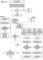
- FIG. 9 is a flowchart for describing an example of a combination of the operation control algorithms of the cooking appliance 1 based on FIGS. 7 and 8 .
- FIG. 9 The flowchart of FIG. 9 is a combination of the operations described individually with reference to FIGS. 7 and 8 . Accordingly, the descriptions provided above with reference to FIGS. 7 and 8 are equally applied, and redundant descriptions thereof are omitted.
- FIG. 9 since the descriptions of FIGS. 7 and 8 are considered together, some operations may be different. This is described below.
- the cooking appliance 1 may sense the internal temperature of the load through the temperature sensor after applying RF basic heating, and may detect brightness by acquiring the image of the outside of the load through the image sensor after applying heater heating.
- the cooking appliance 1 may determine whether the sensed internal temperature of the load has reached the target temperature (first condition) and the external brightness of the load has reached the target brightness (second condition). This may be determined by determining whether Tc>Tc_target and Vo>Vo_target.
- the cooking appliance 1 may perform control to stop heating when both the first and second conditions are satisfied. However, when at least one of the first and second conditions is not satisfied, the cooking appliance 1 may determine again whether the rate of change in temperature and brightness satisfies a predefined criteria. This may be determined based on the change in brightness/change in temperature ( ⁇ Vo/ ⁇ Tc>1) . When the value is greater than or equal to 1, the searing may be determined to be successful (Yes), and when the value is less than 1, the RF may be determined to be successful (No).
- the frequency scan may be performed through RF low power, and after detecting the reflected output, it may be determined whether the reflected output criteria is satisfied. Thereafter, when it is determined that the reflected output satisfies the criteria, the frequency may be determined and it may be determined whether ⁇ Vo> ⁇ Tc. As the result of the determination as to whether ⁇ Vo> ⁇ Tc, when the change in external brightness (Vo) is determined to be greater than the change in internal temperature (Tc), heating control may be performed to increase SSPM output and/or to lower the temperature of the cooking chamber.
- Vo change in external brightness
- Tc change in internal temperature
- the frequency scan may be performed through RF low power, and after detecting the reflected output, it may be determined whether the reflected output criteria is satisfied. Thereafter, when it is determined that the reflected output satisfies the criteria, the frequency may be determined and it may be determined whether ⁇ Vo ⁇ Tc.
- ⁇ Vo ⁇ Tc when the change in external brightness (Vo) is determined to be less than the change in internal temperature (Tc), heating control may be performed to decrease SSPM output and/or to increase the temperature of the cooking chamber.
- the temperature may be sensed again through the temperature sensor and/or the image sensor, and the subsequent procedures may be repeated.
- the cooking appliance 1 may check the real-time heating temperature trend monitored through the temperature sensor based on the preset reference for each cooking condition (temperature by time: slope ⁇ T). The cooking appliance 1 may vary the RF output power based on the checking result. When the temperature over time is lower than the reference temperature, the cooking appliance 1 may re-perform the frequency scan, store the heating frequency, and then increase the RF output. Otherwise, that is, when the temperature is higher than the reference temperature, the cooking appliance 1 may lower the RF output. The process described above continues over time through real-time monitoring through the temperature sensor, and when the preset final temperature (Td) is reached, the cooking appliance 1 may stop cooking the load.
- Td preset final temperature
- the cooking appliance 1 may perform individual control by referring to the reference temperature change amount according to the cooking state in each section.
- SSPM output may be controlled to decrease through frequency variable control.
- SSPM output may be controlled to increase through frequency variable control.
- the cooking appliance 1 may correct the RF output by comparing the load internal temperature value monitored in real time through the temperature sensor based on the reference temperature for each food.
- section A (Ta) since section A (Ta) is higher than the reference temperature, after determining the heating frequency through the frequency scan, the previous SSPM output may be maintained.
- section B (Tb) since the temperature is lower than the reference temperature, the SSPM output may be increased after finding the heating frequency through the frequency scan. This process may continue until the final temperature set by the customer is reached.
- (Section A (Ta) frequency control O, decrease in SSPM output / section B (Tb): frequency control O, increase in SSPM output)
- (b) of FIG. 10 is a graph for describing the output mechanism according to brightness (V) over time. By referring to the reference brightness with linearity, the output may be controlled with reference to the brightness value according to the cooking state for the time unit, that is, the load acquired in each section.
- the cooking appliance 1 may control frequency and heater output power with respect to time based on brightness (V), which is the surface color data of the load monitored through the image sensor.
- V brightness
- the cooking appliance 1 may determine the searing (browning) state based on the degree of doneness according to the initially set degree of doneness of the load and the brightness value of the surface of the load monitored in real time through the image sensor.
- the doneness monitored for each unit time is excessive, it may be controlled to maintain the previous heater output. However, otherwise, that is, when the doneness is low, the output of the heater may be controlled to increase. This process may be continued until the initially set degree of doneness is reached.
- sections B and D (Vb, Vd) decrease in heater output / sections A and C (Va, Bc): increase in heater output
- the cooking appliance 1 may perform frequency control and output control by using both the temperature sensor and the image sensor to determine surface searing (real-time monitoring through the image sensor) and internal cooking progress (real-time monitoring through the temperature sensor).
- FIG. 10 illustrates the output control algorithm according to the ratio of temperature and brightness.
- the output control algorithm may be the basis of the RF variable control algorithm based on the temperature sensor as illustrated in (a) of FIG. 10 and the heater variable control algorithm based on the image sensor as illustrated in (b) of FIG. 10 .
- the cooking appliance 1 may use the temperature sensor and the image sensor together to uniformly heat the inside and outside of the load.
- the output algorithm may be controlled by determining the internal degree of doneness through the temperature sensor and the external degree of doneness through the image sensor.
- the meaning of 'together' may be either simultaneous or sequential.
- by simultaneously controlling the temperature sensor and the image sensor it is possible to more accurately identify the cooking state of the load through more precise monitoring of the inside and outside of the load.
- the uniformity and accuracy of cooking with respect to the load may be improved by performing variable control on the RF output and/or the output of the heater. This has the advantage of reducing customers' failure experiences (burning while cooking, etc.).
- the cooking appliance 1 may determine that the searing (browning) progress on the surface of the load is faster than the internal cooking, such that the temperature of the cooking chamber may be lowered and the RF output may be increased.
- the cooking appliance 1 may determine that cooking inside the load is faster than searing (browning) on the surface of the load, such the temperature of the cooking chamber may be increased and the RF output may be lowered.
- control of the temperature of the cooking chamber may follow the control algorithm according to the food ingredients set at the time of setting.
- section A that is, the section where temperature>brightness
- the internal heating of the load is faster than the surface searing (browning) of the load, and thus, the top heater output may be increased and the SSPM output may be lowered.
- section B that is, the section where brightness>temperature
- the searing (browning) of the surface of the load is faster than the internal heating of the load, and thus, the output of the SSPM may be increased and the output of the top heater may be lowered.
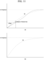
- the cooking appliance 1 may set the heating time according to the initially set temperature and load weight, and may heat up to the set time/temperature by using RF and heater heating without preheating.
- the algorithm during heating is implemented, that is, the output may be controlled through real-time frequency control, slope according to the reference temperature (brightness) by time, or absolute value comparison.
- the dashed line may represent the reference and the solid line may represent the ratio between temperature and brightness monitored in real time.
- the cooking appliance 1 may perform heating (defrosting) up to the set time/temperature by using RF and heater heating without preheating.
- the algorithm during heating is implemented, that is, the output may be controlled through real-time frequency control, slope according to the reference temperature (brightness) by time, or absolute value comparison.
- FIG. 12 is a diagram for describing the output variable control algorithm according to the location of the load.
- the configuration of the output variable control algorithm may be configured to include a temperature sensor 1220 including multi-sensors 1230 and 1240, a controller 260, a top heater 1250, an SSPM 220, and an antenna 230.
- RF through the SSPM 220 may heat the inside of the load, and the top heater 1250 or 310 may heat the outside of the load 1210, thereby heating the entire load evenly.
- each heat source may be controlled by using the multi-sensors for each location, especially in the temperature sensor.
- the first multi-sensor 1230 may control the RF heat source 220 by monitoring the temperature inside the load in real time
- the second multi-sensor 1240 may control the top heater 1250 by monitoring the temperature outside the load in real time. In this way, faster and more uniform heating is possible by simultaneously monitoring not only the inside of the load but also the outside of the load through the temperature sensor 1220 including the multi-sensors.
- real-time monitoring is performed for each location (depth) of the load by using the multi-sensors of the temperature sensor 1220 to control the corresponding heat source.
- Variable control may be performed on the RF output by using the temperature value measured through the first multi-sensor 1230 and the temperature value measured through the second multi-sensor 1240.
- the heater 1250 may not be an essential component.
- the second multi-sensor 1240 is preferably positioned (inserted) relatively closer to the surface of the load 1210 than the first multi-sensor 1230.
- the temperature sensor 1220 may include an indicator (not shown) that may identify the location of each multi-sensor within the load.
- the indicator may be implemented to be identified not only visually but also through sound output in relation to hearing.
- the temperature sensor 1220 may include a plurality of multi-sensors in an insertion portion 1225.
- the location of the multi-sensor is not differentiated compared to the size of the load, and thus, it may be difficult to acquire an accurate temperature sensing value for the cooking state of the load.
- a plurality of sensors may be arranged at predetermined intervals in the insertion portion 1225.
- at least two or more multi-sensors may be activated to acquire the internal temperature value of the load, which may be used for RF and/or variable heater control.
- the insertion portion 1225 may be implemented in a form in which the length may be reduced or extended in consideration of the size of the load, etc.
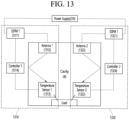
- FIG. 13 is a diagram for describing multi-point control by using a multi-temperature sensor.
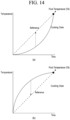
- (a) of FIG. 14 is a graph for describing the heating performance of a first antenna at location 1
- (b) of FIG. 14 is a graph for describing the heating performance of a second antenna at location 2.
- each temperature sensor constituting the multi-temperature sensor may or may not have a plurality of multi-sensors in the insertion portion as illustrated in FIG. 12 .
- each temperature sensor may be independently or individually controlled.
- a first processor 1310 may include a first SSPM 1311, a first antenna 1312, a first temperature sensor 1313, and a controller 1314 and may perform variable control on the RF output after sensing the temperature of the load at the first location.
- a second processor 1320 may include a second SSPM 1321, a second antenna 1322, a second temperature sensor 1323, and a controller 1324 and may perform variable control on the RF output after sensing the temperature of the load at the second location.
- the temperature of the load at the left and right locations may be monitored through the respective temperature sensors 1313 and 1323, and the left and right SSPMs 1311 and 1321 may be independently controlled.
- the RF output power of the first antenna 1312 may be increased through the first SSPM 1311.
- the RF output power of the second antenna 1322 may be increased through the second SSPM 1321.
- the load may be controlled to be uniformly heated by individually sensing the temperature according to the location of the load and individually controlling the SSPM and the antenna.
- controllers 1314 and 1324 are arranged individually. However, only one controller (integrated controller) is provided and the processes 1310 and 1320 may be individually controlled.
- the final target temperature for uniform heating is the same, but the heating performance of the second antenna 1312 may be configured to be superior to the heating performance of the first antenna 1312. In this case, the output of the second antenna 1322 is lowered and the output of the first antenna 1312 is increased to ensure uniform heating by matching performance to the same temperature for the same time.
- the configuration may be opposite to that described above.
- the multi-temperature sensor is used like in FIG. 13 .
- the first processor 1310 may be configured to control the RF output after temperature sensing
- the second processor 1510 may be configured to control the output of the heater 1412 through the second controller 1413 after temperature sensing.
- FIG. 16 the arrangement and structure when using the multi-sensors are described.
- the multi-sensors may refer to at least two sensors.
- the sensor may represent a temperature sensor.
- the sensor may refer to an image sensor.
- an example in which the sensor is a temperature sensor is described.
- the cooking appliance 1 may configure a separate processor for each sensor.
- the cooking appliance 1 may configure a processor for one or more sensors.
- a plurality of processor may be provided, but the present disclosure is not limited thereto.
- each temperature sensor and related components may be implemented in the form illustrated in (b) to (e) of FIG. 16 .
- the present disclosure is not limited thereto.
- a left and right independent control method may be named and described
- a top and bottom independent control method may be named and described
- a four-way independent control method may be named and described.
- (d) of FIG. 16 is a corner or geon/gon/gam/yi control method
- (e) of FIG. 16 is four directions, i.e., east, west, south, and north, but may not be about the corners of the load.
- FIG. 17 describes a movable antenna.
- each antenna may be rotatable at the position although the position is fixed. In this manner, an RF radiation angle toward the load may vary.
- each antenna is fixed, but the own angle thereof may be changed. Accordingly, the RF radiation angle with respect to the load may vary.
- the respective antennas may not be fixed to specific locations, but may be implemented to be movable in any direction on the corresponding plane (i.e., above the cavity 4).
- the respective antennas may also be implemented to be rotatable and/or adjustable in the own angle thereof.
- the cooking appliance 1 may detect temperature/brightness through the sensor (S310) and determine whether the target temperature criteria for each location is satisfied (S320).
- the above-described process may be repeated by controlling the angle, location, rotation, etc. of at least one antenna.
- cooking may be stopped (S330).
- the respective sensors may individually function as a single sensor for different loads or may function as the multi-sensor. Therefore, the above description may be inferred and applied to a plurality of loads.
- the accuracy of monitoring the state of the load through RF scan alone is low. Accordingly, by controlling the characteristics (frequency, output, etc.) of the heat source based on real-time temperature monitoring inside the load through the sensor, cooking accuracy for load may be further improved to enable sophisticated cooking.
- the multi-sensors within one sensor, it is possible to monitor not only the internal temperature but also the external temperature of the load in real time. At this time, one sub-sensor controls the RF output by monitoring the temperature inside the load in real time, and the other sub-sensor controls the output of the heater by monitoring the temperature outside the load in real time. Accordingly, faster and more uniform heating is enabled.
- the multi-sensors may be used to perform control through real-time monitoring of multiple locations (or points) within the load. For example, more sophisticated cooking becomes possible by independent control through antennas placed on the left and right.
Landscapes
- Physics & Mathematics (AREA)
- Electromagnetism (AREA)
- Engineering & Computer Science (AREA)
- Multimedia (AREA)
- General Physics & Mathematics (AREA)
- Theoretical Computer Science (AREA)
- Computer Vision & Pattern Recognition (AREA)
- Signal Processing (AREA)
- Food Science & Technology (AREA)
- Electric Ovens (AREA)
- Control Of High-Frequency Heating Circuits (AREA)
- Electric Stoves And Ranges (AREA)
Applications Claiming Priority (1)
| Application Number | Priority Date | Filing Date | Title |
|---|---|---|---|
| KR1020230068507A KR20240170260A (ko) | 2023-05-26 | 2023-05-26 | 조리기기 |
Publications (2)
| Publication Number | Publication Date |
|---|---|
| EP4468823A2 true EP4468823A2 (de) | 2024-11-27 |
| EP4468823A3 EP4468823A3 (de) | 2025-02-12 |
Family
ID=91247382
Family Applications (1)
| Application Number | Title | Priority Date | Filing Date |
|---|---|---|---|
| EP24178012.1A Pending EP4468823A3 (de) | 2023-05-26 | 2024-05-24 | Kochgerät |
Country Status (3)
| Country | Link |
|---|---|
| US (1) | US20240397591A1 (de) |
| EP (1) | EP4468823A3 (de) |
| KR (1) | KR20240170260A (de) |
Families Citing this family (1)
| Publication number | Priority date | Publication date | Assignee | Title |
|---|---|---|---|---|
| KR20250025858A (ko) * | 2023-08-16 | 2025-02-25 | 엘지전자 주식회사 | 조리기기의 청소 제어방법 |
Family Cites Families (3)
| Publication number | Priority date | Publication date | Assignee | Title |
|---|---|---|---|---|
| ITPN20050058A1 (it) * | 2005-08-23 | 2007-02-24 | Electrolux Professional Spa | "forno a microonde con sonda perfezionata" |
| CN112469945A (zh) * | 2018-07-31 | 2021-03-09 | 松下知识产权经营株式会社 | 高频加热装置 |
| US11035742B2 (en) * | 2018-09-19 | 2021-06-15 | Nuwave, Llc | Wired temperature probe for cooking appliance |
-
2023
- 2023-05-26 KR KR1020230068507A patent/KR20240170260A/ko active Pending
-
2024
- 2024-05-24 EP EP24178012.1A patent/EP4468823A3/de active Pending
- 2024-05-24 US US18/674,516 patent/US20240397591A1/en active Pending
Also Published As
| Publication number | Publication date |
|---|---|
| US20240397591A1 (en) | 2024-11-28 |
| KR20240170260A (ko) | 2024-12-03 |
| EP4468823A3 (de) | 2025-02-12 |
Similar Documents
| Publication | Publication Date | Title |
|---|---|---|
| US11650105B2 (en) | Temperature probe systems and methods | |
| US10271388B2 (en) | Microwave heating apparatus | |
| EP0794387B1 (de) | Verfahren zum einschätzen der temperatur im innern von einem zu kochenden produkt und thermisches kochgerät dafür | |
| JP2017504159A (ja) | マルチ供給高周波デバイスを較正する方法 | |
| JP2020514943A (ja) | 効率の変動係数を使用して食品負荷特性の変化を検出するためのシステムおよび方法 | |
| JP2013510399A (ja) | Rfエネルギーを使用して加熱するためのデバイスおよび方法 | |
| CN108670049B (zh) | 射频加热设备的加热食物方法 | |
| US20220030677A1 (en) | Method for operating a domestic cooking appliance and domestic cooking appliance | |
| US20200281391A1 (en) | Sous-vide oven mode with probe | |
| EP4468823A2 (de) | Kochgerät | |
| CN113662421A (zh) | 烹饪器具及其控制方法和控制装置、可读存储介质 | |
| JP2864998B2 (ja) | 加熱調理装置 | |
| JP6775023B2 (ja) | 食品を調理するために高周波電磁エネルギーを伝達する方法および装置 | |
| JP2018054250A (ja) | 加熱調理器 | |
| JP7538997B2 (ja) | 高周波加熱装置 | |
| CN114051766B (zh) | 具有模式改变设备的家用微波器具 | |
| US20180168008A1 (en) | Cooking apparatus | |
| KR100314441B1 (ko) | 가열장치의온도제어방법 | |
| EP4468824A1 (de) | Kochgerät | |
| JP2014070875A (ja) | 高周波加熱装置 | |
| KR20210095424A (ko) | 조리 기기 및 그 제어 방법 | |
| JPH06249447A (ja) | 高周波加熱装置とそれを用いたパン検知方法 | |
| WO2023237207A1 (en) | Method for operating a cooking appliance | |
| JPH0833206B2 (ja) | 調理器 | |
| JPH0833209B2 (ja) | 調理器 |
Legal Events
| Date | Code | Title | Description |
|---|---|---|---|
| PUAI | Public reference made under article 153(3) epc to a published international application that has entered the european phase |
Free format text: ORIGINAL CODE: 0009012 |
|
| STAA | Information on the status of an ep patent application or granted ep patent |
Free format text: STATUS: REQUEST FOR EXAMINATION WAS MADE |
|
| 17P | Request for examination filed |
Effective date: 20240624 |
|
| AK | Designated contracting states |
Kind code of ref document: A2 Designated state(s): AL AT BE BG CH CY CZ DE DK EE ES FI FR GB GR HR HU IE IS IT LI LT LU LV MC ME MK MT NL NO PL PT RO RS SE SI SK SM TR |
|
| PUAL | Search report despatched |
Free format text: ORIGINAL CODE: 0009013 |
|
| AK | Designated contracting states |
Kind code of ref document: A3 Designated state(s): AL AT BE BG CH CY CZ DE DK EE ES FI FR GB GR HR HU IE IS IT LI LT LU LV MC ME MK MT NL NO PL PT RO RS SE SI SK SM TR |
|
| RIC1 | Information provided on ipc code assigned before grant |
Ipc: H05B 6/68 20060101ALI20250107BHEP Ipc: H05B 6/64 20060101AFI20250107BHEP |