EP4468637A1 - Codierungsverfahren, vorrichtung und lesbares speichermedium - Google Patents
Codierungsverfahren, vorrichtung und lesbares speichermedium Download PDFInfo
- Publication number
- EP4468637A1 EP4468637A1 EP23742773.7A EP23742773A EP4468637A1 EP 4468637 A1 EP4468637 A1 EP 4468637A1 EP 23742773 A EP23742773 A EP 23742773A EP 4468637 A1 EP4468637 A1 EP 4468637A1
- Authority
- EP
- European Patent Office
- Prior art keywords
- coding
- symbol period
- transmit
- symbol
- symbols
- Prior art date
- Legal status (The legal status is an assumption and is not a legal conclusion. Google has not performed a legal analysis and makes no representation as to the accuracy of the status listed.)
- Pending
Links
Images




Classifications
-
- H—ELECTRICITY
- H04—ELECTRIC COMMUNICATION TECHNIQUE
- H04L—TRANSMISSION OF DIGITAL INFORMATION, e.g. TELEGRAPHIC COMMUNICATION
- H04L5/00—Arrangements affording multiple use of the transmission path
- H04L5/003—Arrangements for allocating sub-channels of the transmission path
- H04L5/0048—Allocation of pilot signals, i.e. of signals known to the receiver
-
- H—ELECTRICITY
- H04—ELECTRIC COMMUNICATION TECHNIQUE
- H04L—TRANSMISSION OF DIGITAL INFORMATION, e.g. TELEGRAPHIC COMMUNICATION
- H04L1/00—Arrangements for detecting or preventing errors in the information received
- H04L1/02—Arrangements for detecting or preventing errors in the information received by diversity reception
- H04L1/06—Arrangements for detecting or preventing errors in the information received by diversity reception using space diversity
- H04L1/0618—Space-time coding
- H04L1/0637—Properties of the code
- H04L1/0643—Properties of the code block codes
-
- H—ELECTRICITY
- H04—ELECTRIC COMMUNICATION TECHNIQUE
- H04B—TRANSMISSION
- H04B7/00—Radio transmission systems, i.e. using radiation field
- H04B7/02—Diversity systems; Multi-antenna system, i.e. transmission or reception using multiple antennas
- H04B7/04—Diversity systems; Multi-antenna system, i.e. transmission or reception using multiple antennas using two or more spaced independent antennas
- H04B7/06—Diversity systems; Multi-antenna system, i.e. transmission or reception using multiple antennas using two or more spaced independent antennas at the transmitting station
- H04B7/0613—Diversity systems; Multi-antenna system, i.e. transmission or reception using multiple antennas using two or more spaced independent antennas at the transmitting station using simultaneous transmission
- H04B7/0667—Diversity systems; Multi-antenna system, i.e. transmission or reception using multiple antennas using two or more spaced independent antennas at the transmitting station using simultaneous transmission of delayed versions of same signal
- H04B7/0669—Diversity systems; Multi-antenna system, i.e. transmission or reception using multiple antennas using two or more spaced independent antennas at the transmitting station using simultaneous transmission of delayed versions of same signal using different channel coding between antennas
-
- H—ELECTRICITY
- H04—ELECTRIC COMMUNICATION TECHNIQUE
- H04L—TRANSMISSION OF DIGITAL INFORMATION, e.g. TELEGRAPHIC COMMUNICATION
- H04L1/00—Arrangements for detecting or preventing errors in the information received
- H04L1/02—Arrangements for detecting or preventing errors in the information received by diversity reception
- H04L1/06—Arrangements for detecting or preventing errors in the information received by diversity reception using space diversity
- H04L1/0612—Space-time modulation
-
- H—ELECTRICITY
- H04—ELECTRIC COMMUNICATION TECHNIQUE
- H04L—TRANSMISSION OF DIGITAL INFORMATION, e.g. TELEGRAPHIC COMMUNICATION
- H04L1/00—Arrangements for detecting or preventing errors in the information received
- H04L1/02—Arrangements for detecting or preventing errors in the information received by diversity reception
- H04L1/06—Arrangements for detecting or preventing errors in the information received by diversity reception using space diversity
- H04L1/0618—Space-time coding
- H04L1/0637—Properties of the code
-
- H—ELECTRICITY
- H04—ELECTRIC COMMUNICATION TECHNIQUE
- H04L—TRANSMISSION OF DIGITAL INFORMATION, e.g. TELEGRAPHIC COMMUNICATION
- H04L1/00—Arrangements for detecting or preventing errors in the information received
- H04L1/02—Arrangements for detecting or preventing errors in the information received by diversity reception
- H04L1/06—Arrangements for detecting or preventing errors in the information received by diversity reception using space diversity
- H04L1/0618—Space-time coding
- H04L1/0637—Properties of the code
- H04L1/0668—Orthogonal systems, e.g. using Alamouti codes
-
- H—ELECTRICITY
- H04—ELECTRIC COMMUNICATION TECHNIQUE
- H04L—TRANSMISSION OF DIGITAL INFORMATION, e.g. TELEGRAPHIC COMMUNICATION
- H04L1/00—Arrangements for detecting or preventing errors in the information received
- H04L1/02—Arrangements for detecting or preventing errors in the information received by diversity reception
- H04L1/06—Arrangements for detecting or preventing errors in the information received by diversity reception using space diversity
- H04L1/0618—Space-time coding
- H04L1/0675—Space-time coding characterised by the signaling
-
- H—ELECTRICITY
- H04—ELECTRIC COMMUNICATION TECHNIQUE
- H04L—TRANSMISSION OF DIGITAL INFORMATION, e.g. TELEGRAPHIC COMMUNICATION
- H04L5/00—Arrangements affording multiple use of the transmission path
- H04L5/22—Arrangements affording multiple use of the transmission path using time-division multiplexing
- H04L5/225—Arrangements affording multiple use of the transmission path using time-division multiplexing combined with the use of transition coding
-
- H—ELECTRICITY
- H04—ELECTRIC COMMUNICATION TECHNIQUE
- H04B—TRANSMISSION
- H04B7/00—Radio transmission systems, i.e. using radiation field
- H04B7/02—Diversity systems; Multi-antenna system, i.e. transmission or reception using multiple antennas
-
- H—ELECTRICITY
- H04—ELECTRIC COMMUNICATION TECHNIQUE
- H04L—TRANSMISSION OF DIGITAL INFORMATION, e.g. TELEGRAPHIC COMMUNICATION
- H04L1/00—Arrangements for detecting or preventing errors in the information received
- H04L1/02—Arrangements for detecting or preventing errors in the information received by diversity reception
- H04L1/06—Arrangements for detecting or preventing errors in the information received by diversity reception using space diversity
- H04L1/0618—Space-time coding
- H04L1/0625—Transmitter arrangements
-
- H—ELECTRICITY
- H04—ELECTRIC COMMUNICATION TECHNIQUE
- H04L—TRANSMISSION OF DIGITAL INFORMATION, e.g. TELEGRAPHIC COMMUNICATION
- H04L1/00—Arrangements for detecting or preventing errors in the information received
- H04L1/02—Arrangements for detecting or preventing errors in the information received by diversity reception
- H04L1/06—Arrangements for detecting or preventing errors in the information received by diversity reception using space diversity
- H04L1/0618—Space-time coding
- H04L1/0637—Properties of the code
- H04L1/0662—Limited orthogonality systems
Definitions
- This application pertains to the field of communication technologies and specifically relates to a coding method and apparatus and a readable storage medium.
- Orthogonal space time block code Orthogonal Space Time Block Code
- OSTBC Orthogonal Space Time Block Code
- Alamouti code can achieve full diversity gain and full rate.
- OSTBC Orthogonal Space Time Block Code
- a decoding end is required to know the channel state information (Channel State Information, CSI) between all transmit and receive antennas.
- CSI Channel State Information
- Embodiments of this application provide a coding method and apparatus and a readable storage medium, to solve the problems that the decoding end cannot reduce the complexity of system implementation and be applicable for nonconstant modulation, without knowing the CSI between all transmit and receive antennas.
- a coding method including:
- a coding apparatus includes:
- a coding end includes a processor and a memory, where the memory has stored thereon a program or instructions capable of running on the processor.
- the program or instructions are executed by the processor, the steps of the method according to the first aspect are implemented.
- a coding end including a processor and a communication interface, where the processor is configured for a coding end to perform coding through a DSTBC scheme, an NSTBC codebook, and a power sum of transmit symbols on a transmit antenna in previous two symbol periods to obtain a transmit symbol for a current symbol period.
- the coding end determines a transmit symbol for a symbol period next to the current symbol period based on the transmit symbol for the current symbol period and the NSTBC codebook, where the previous two symbol periods are two adjacent symbol periods preceding the current symbol period.
- a readable storage medium where the readable storage medium has stored thereon a program or instructions, and when the program or instructions are executed by a processor, the steps of the method according to the first aspect are implemented.
- a chip includes a processor and a communication interface.
- the communication interface is coupled to the processor, and the processor is configured to run a program or instructions to implement the method according to the first aspect.
- a computer program product is provided, where the computer program product is stored in a storage medium, and the computer program/program product is executed by at least one processor to implement the steps of the method according to the first aspect.
- a communication device configured to perform the steps of the method according to the first aspect.
- a DSTBC scheme, an NSTBC codebook, and a power sum of transmit symbols on a transmit antenna in previous two symbol periods are used to calculate a transmit symbol for a current symbol period, and additionally, the NSTBC codebook with low complexity is used to calculate a transmit symbol for a next symbol period.
- the NSTBC codebook can help to reduce the number of load impedance types on the antenna while ensuring diversity gain, reduce the complexity of system implementation, and effectively reduce the probability of detection errors.
- first, second, and the like in this specification and claims of this application are used to distinguish between similar objects rather than to describe a specific order or sequence. It should be understood that terms used in this way are interchangeable in appropriate circumstances so that the embodiments of this application can be implemented in other orders than the order illustrated or described herein.
- first and second are usually used to distinguish objects of a same type, and do not restrict a quantity of objects. For example, there may be one or a plurality of first objects.
- “and/or” in the specification and claims represents at least one of connected objects, and the character “/" generally indicates that the associated objects have an "or” relationship.
- technologies described in the embodiments of this application are not limited to long term evolution (Long Term Evolution, LTE) or LTE-Advanced (LTE-Advanced, LTE-A) systems, and may also be applied to other wireless communication systems, for example, code division multiple access (Code Division Multiple Access, CDMA), time division multiple access (Time Division Multiple Access, TDMA), frequency division multiple access (Frequency Division Multiple Access, FDMA), orthogonal frequency division multiple access (Orthogonal Frequency Division Multiple Access, OFDMA), single-carrier frequency-division multiple access (Single-carrier Frequency Division Multiple Access, SC-FDMA), and other systems.
- code division multiple access Code Division Multiple Access
- Time Division Multiple Access Time Division Multiple Access
- FDMA frequency division multiple access
- OFDMA Orthogonal frequency division multiple access
- SC-FDMA single-carrier Frequency Division Multiple Access
- system and “network” in the embodiments of this application are often used interchangeably, and the technology described herein may be used in the above-mentioned systems and radio technologies as well as other systems and radio technologies.
- NR New Radio
- NR terms are used in most of the following descriptions, although these technologies may also be applied to other applications than an NR system application, for example, the 6th generation (6 th Generation, 6G) communication system.
- a coding end can be deployed on a sending device, which may be, for example, a terminal or a network-side device.
- the terminal can be a terminal-side device, such as a mobile phone, a tablet personal computer (Tablet Personal Computer, TPC), a laptop computer (Laptop computer, LC) or a notebook computer, a personal digital assistant (Personal Digital Assistant, PDA), a palmtop computer, a netbook, an ultra-mobile personal computer (Ultra-Mobile Personal Computer, UMPC), a mobile Internet device (Mobile Internet Device, MID), an augmented reality (Augmented Reality, AR)/virtual reality (Virtual Reality, VR) device, a robot, a wearable device (Wearable Device, WD), vehicle user equipment (Vehicle User Equipment, VUE), or pedestrian user equipment (Pedestrian User Equipment, PUE), a smart appliance (a home appliance with a wireless communication function, for example, a refrigerator, a television, a washing machine, or
- the wearable device includes a smart watch, a smart band, a smart earphone, smart glasses, smart jewelry (a smart bangle, a smart bracelet, a smart ring, a smart necklace, a smart ankle bangle, a smart anklet, or the like), a smart wristband, smart clothing, or the like.
- the network-side device can include an access network device or core network device, where the access network device can also be referred to as a radio access network device, radio access network (Radio Access Network, RAN), radio access network function, or radio access network unit.
- RAN Radio Access Network
- the access network device can include base stations, wireless local area network (Wireless Local Area Networks, WLAN) access points, wireless fidelity (Wireless Fidelity, WiFi) nodes, or the like.
- the base station can be referred to as Node B, evolved Node B (eNB), access point, base transceiver station (Base Transceiver Station, BTS), radio base station, radio transceiver, basic service set (Basic Service Set, BSS), extended service set (Extended Service Set, ESS), home Node B, home evolved Node B, transmitting receiving point (Transmitting Receiving Point, TRP), or other appropriate terms in the field.
- the base station is not limited to any specific technical terminology.
- the core network device can include but is not limited to at least one of the following: core network node, core network function, mobility management entity (Mobility Management Entity, MME), access and mobility management function (Access and Mobility Management Function, AMF), session management function (Session Management Function, SMF), user plane function (User Plane Function, UPF), policy control function (Policy Control Function, PCF), policy and charging rules function (Policy and Charging Rules Function, PCRF), edge application server discovery function (Edge Application Server Discovery Function, EASDF), unified data management (Unified Data Management, UDM), unified data repository (Unified Data Repository, UDR), home subscriber server (Home Subscriber Server, HSS), centralized network configuration (Centralized network configuration, CNC), network repository function (Network Repository Function, NRF), network exposure function (Network Exposure Function, NEF), local NEF (L
- a future 6G communication network needs to support massive Internet of Everything, where the number of Internet of Things devices will reach hundreds of billions, and its connection density will be 10 to 100 times higher than that of the 5th generation (5 th Generation, 5G) communication system, reaching a connection density of 10 to 100 devices per square meter.
- Massive Internet of Things devices pose new challenges to both cost and power consumption.
- Cellular networking, low cost, low power consumption, and even zero power consumption are main trends in the development of Internet of Things devices in the future.
- Conventional passive terminals are limited by their power consumption and hardware capabilities, and their communication transmission distances are mostly below 10 meters, far from the goal of cellular coverage of 100 meters. Therefore, how the communication distances of passive terminals are effectively increased has become a difficult problem to be solved after the cellular networking of this technology.
- the amplitude or phase of a signal is controlled by changing the load impedance in backscatter communication (Backscatter Communication, BSC), in considering other non-ideal factors in the backscatter communication modulation circuit, the amplitude or phase of an output signal has more or less errors. However, as long as these signal errors are within a resolvable range, they have no effect on signal demodulation. Therefore, if the number or types of load impedances to be controlled on the antenna are less, the tolerable error can be greater, and the probability of detection errors can be lower.
- BSC Backscatter Communication
- BSC UE backscatter communication device
- Backscatter communication means that a backscatter communication device uses radio frequency signals from another device or the environment for signal modulation to transmit its own information.
- a modulation circuit thereof is shown in FIG. 1a .
- a backscatter communication device can be a tag in conventional radio frequency identification (Radio Frequency Identification, RFID), or passive/semi-passive Internet of Things (Passive/Semi-passive Internet of Things, IoT). For convenience, they are collectively referred to as BSC UEs herein.
- RFID Radio Frequency Identification
- IoT passive/semi-passive Internet of Things
- Constant modulation and nonconstant modulation Constant modulation and nonconstant modulation (Constant Modulation and Nonconstant Modulation).
- Typical modulation techniques can be divided into constant modulation and nonconstant modulation.
- the so-called constant modulation means that powers or amplitudes of modulated symbol constellation points are the same, and a typical constant modulation is MPSK.
- nonconstant modulation means that powers or amplitudes of modulated symbol constellation points are different, and typical nonconstant modulation includes APSK, QAM, and the like.
- Orthogonal space time block code Orthogonal Space Time Block Code, OSTBC
- STBC Space time block code
- I represents an identity matrix with dimension M
- i represents the i-th element of dimension M
- s i is a diagonal element
- elements in the i-th row in S represent symbols transmitted on the i-th transmit antenna within M time instants
- elements in the j-th column in S represent symbols transmitted on n t antennas at the j -th time instant.
- Columns in the transmission matrix S satisfying the foregoing formula are mutually orthogonal, which means that transmitted signal sequences on different antennas are also orthogonal, thus ensuring that STBC can achieve full diversity gain at the same time.
- Its corresponding decoding end only needs to perform simple maximal ratio combining (Maximal ratio combining, MRC) to sequentially decouple the transmit symbols from different antennas, and then performs detection and estimation through the maximum likelihood (Maximum likelihood, ML) algorithm.
- Alamouti code is the most representative OSTBC code and can achieve full diversity and full rate gain.
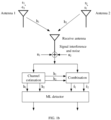
- FIG. 1b is a principle block diagram of Alamouti code.
- s 1 the symbol transmitted on antenna 1
- s 2 the symbol transmitted on antenna 2
- S the symbol transmitted on antenna 1
- New Space Time Block Code (New Space Time Block Code, NSTBC)
- the symbol transmitted on antenna 1 is denoted as s 1
- the symbol transmitted on antenna 2 is denoted as s 2 ⁇
- the symbol transmitted on antenna 1 is s 2
- the symbol transmitted on antenna 2 is ( ⁇ s 1 ⁇ ).
- S 2 belongs to OSTBC codeword and thus can achieve full diversity gain and full rate transmission. The following analysis compares differences between this type of codeword and the conventional Alamouti code in backscatter communication.
- Tables 3 and 4 also give coding tables of Alamouti codeword and extended Alamouti codeword when two antennas transmit different symbols at two antennas simultaneously, where the extended Alamouti codeword is: s 1 s 2 s 2 ⁇ ⁇ s 1 ⁇ .
- antenna 1 only needs two coefficients
- antenna 1 and antenna 2 both need four coefficients
- This method can be extended to scenarios with four or more antennas.
- DSTBC Differential space time block code
- the decoding end adopts a decoding scheme of coherent detection, so the decoding end needs precise channel state information (Chanel State Information, CSI) from the transmit antenna to the receive antenna.
- CSI Channel State Information
- the decoding end cannot obtain ideal CSI information.
- Differential space time block coding is a scheme in which neither the coding end nor the decoding end needs to know CSI information, and the coding and decoding processes are simple while still achieving diversity gain. The following is described with an example using two antennas for transmitting and one antenna for receiving.
- s 1 , s 2 transmitted in these two transmissions carries no information, but only serves as a reference signal.
- the coding end uses differential coding scheme for transmission. It is assumed that in the (2t - 1)-th symbol period, the symbols transmitted from a first antenna and a second antenna are s 2t-1 and s 2t , respectively, in the 2t-th symbol period, the symbols transmitted from the first antenna and the second antenna are ⁇ s 2t ⁇ and s 2t ⁇ 1 ⁇ , respectively. In the (2t + 1)-th symbol period, a group of 2m bits arrive at the coding end, and a corresponding coding coefficient vector (A( ), B( )) is generated.
- the coding end calculates the symbol transmitted in the current (2t + 1)-th symbol period based on symbol vectors transmitted in the previous two symbol periods and a current coding coefficient vector (A( ), B( )).
- s 2 t + 1 s 2 t + 2 A D 2 t + 1 s 2 t ⁇ 1 s 2 t + B D 2 t + 1 ⁇ s 2 t ⁇ , s 2 t ⁇ 1 ⁇ .
- repeated coding is performed on the transmit symbols.
- ⁇ ⁇ 1 ⁇ 2 ⁇ 1 ⁇ 2 * ⁇ 2 ⁇ ⁇ 1 * ;
- R 1 ⁇ 1 2 + ⁇ 2 2 A D 2 t ⁇ 1 + N 1 .
- R 2 r 2 t + 1 r 2 t * ⁇ r 2 t + 2 * r 2 t ⁇ 1
- N 2 s 2 t + 1 s 2 t + 2 ⁇ ⁇ 1 ⁇ 2 N 2 t * + N 2 t + 1 ⁇ * ⁇ 1 ⁇ 2 ⁇ s 2 t , s 2 t ⁇ 1 + N 2 t + 1 N 2 t * ;
- R 2 ⁇ 1 2 + ⁇ 2 2 B D 2 t ⁇ 1 + N 2 .
- R 1 R 2 ⁇ 1 2 + ⁇ 2 2 A D 2 t + 1 , B D 2 t + 1 + N 1 N 2 .
- a receiver selects a coding coefficient vector ( ⁇ ( ), B ⁇ ( )) that has a shortest Euclidean distance to a decision and statistical signal vector ( ) as a decoding output:
- a ⁇ D 2 t + 1 , B ⁇ D 2 t + 1 arg min A D 2t + 1 ,B D 2t + 1 ⁇ V A D 2t + 1 , B D 2 t + 1 ⁇ R 1 R 2 2 .
- Conventional OSTBC type codebooks can achieve full diversity gain and full rate. However, they are designed for conventional active radio frequency communication without considering the modulation characteristics and implementation complexity of passive terminals performing, for example, backscatter communication. Additionally, the decoding end is required to know the channel state information CSI between all transmit and receive antennas.
- the NSTBC codebook proposed for backscatter communication reduces the complexity of hardware implementation and the probability of detection errors by optimizing the codebook of conventional Alamouti code, but this method requires the decoding end to know the CSI information between all transmit and receive antennas.
- the conventional differential space time block coding based on Alamouti do not need to know the CSI information between all transmit and receive antennas, they do not consider the modulation characteristics and implementation complexity of passive terminals performing, for example, backscatter communication.
- the conventional differential space time block coding is only suitable for constant modulation such as MPSK.
- constant modulation such as MPSK.
- nonconstant modulations such as APSK or QAM
- conventional differential space time block coding and decoding schemes cannot be directly applied due to different energies of symbols in each constellation.
- constellation shaping gain brought by nonconstant modulation compared with constant modulation and the difference between amplitude modulation and phase modulation capabilities in backscatter communication, it is necessary to solve the coding and decoding problems of differential space time block code based on nonconstant modulation.
- an embodiment of this application provides a coding method.
- the method is executed by a coding end, and the coding end may be a terminal device or a network-side device.
- the method includes:
- the previous two symbol periods are two adjacent symbol periods preceding the current symbol period.
- a DSTBC scheme, an NSTBC codebook, and a power sum of transmit symbols on a transmit antenna in previous two symbol periods are used to calculate a transmit symbol for a current symbol period, and additionally, the NSTBC codebook with low complexity is used to calculate a transmit symbol for a next symbol period.
- the NSTBC codebook can help to reduce the number of load impedance types on the antenna while ensuring diversity gain, reduce the complexity of system implementation, and effectively reduce the probability of detection errors.
- the coding method provided in this embodiment of this application is to calculate the symbol for the current symbol period by combining the DSTBC scheme with the NSTBC codebook and performing power normalization, extracting advantages of both, so that no pilot signal needs to be transmitted on each transmit antenna, reducing system overheads, and in addition, achieving applicability to nonconstant modulation and obtaining the constellation shaping gain.
- use of the NSTBC codebook can help to reduce the number of load impedance types on the antenna while ensuring diversity gain, reduce the complexity of system implementation, and effectively reduce the probability of detection errors.
- This new type of coding method can be called nonconstant differential NSTBC coding method.
- the nonconstant differential NSTBC coding method in this embodiment of this application can be applied to scenarios with two-antenna transmit diversity.
- the transmit symbols in this embodiment of this application are constant modulation symbols or nonconstant modulation symbols, where constant modulation at least includes BPSK modulation and multiple phase shift keying (Multiple Phase Shift Keying, MPSK); and nonconstant modulation at least includes APSK modulation.
- the modulation schemes adopted by the coding end can include binary phase shift keying (Binary Phase Shift Keying, BPSK) and amplitude phase shift keying (Amplitude Phase Shift Keying, APSK).
- the NSTBC codebook is used for space-time block coding, or the NSTBC codebook is used for polarization-time block coding, that is, two transmit antennas can be isolated spatially or in polarization.
- the polarization mode includes one or more of the following: horizontal polarization, vertical polarization, left-handed elliptical polarization, right-handed elliptical polarization, left-handed circular polarization, and right-handed circular polarization.
- a mapping relationship is present between the original bits for the current symbol period and the transmit symbol for the current symbol period.
- mapping relationship from (M,N)-APSK (taking APSK as an example for illustration) to the NSTBC codebook is first designed, where M represents the amplitude order of APSK and N represents the phase type of APSK.
- antenna 1 Compared with the coding tables based on BPSK modulation in Tables 3 to 5, in Tables 6 and 7, based on APSK modulation, there are fewer phase types on some antennas.
- antenna 1 only needs to support one phase, namely e j ⁇ , and two amplitudes
- antenna 2 needs to support two phases e -j ⁇ and e -j( ⁇ + ⁇ ) and two amplitudes
- antennas 1 and 2 need to support two amplitudes and two phases
- antennas 1 and 2 need to support one amplitude and four phases.
- APSK reduces the number of impedance matching types that support phase modulation by increasing the number of impedance matching types that support amplitude modulation on some antennas, which is beneficial for backscatter communication in some cases in which the amplitude modulation capability is better than the phase modulation capability.
- antenna 1 in the NSTBC codebook coding table only needs to support one phase, while antenna 1 in the Alamouti codebook coding table needs to support two phases. Therefore, the NSTBC codebook can reduce the number of impedance matching types for phase modulation of the antenna 1.
- NSTBC and ABBA-class four-antenna transmit diversity coding tables based on APSK modulation are shown in Table 8 and Table 9, respectively, where Table 8 is a four-antenna transmit diversity coding table for NSTBC based on (2,1)-APSK modulation, and Table 9 is a four-antenna transmit diversity coding table for ABBA-class quasi-orthogonal space time block code (QSTBC) based on (2,1)-APSK modulation.
- QSTBC quasi-orthogonal space time block code
- the ABBA-class codebook is as follows: s 1 s 2 s 3 s 4 s 2 ⁇ ⁇ s 1 ⁇ s 4 ⁇ ⁇ s 3 ⁇ s 3 s 4 s 1 s 2 s 4 ⁇ ⁇ s 3 ⁇ s 2 ⁇ ⁇ s 1 ⁇ Table 8 0000 Antenna 1 Antenna 2 Antenna 3 Antenna 4 0001 Antenna 1 Antenna 2 Antenna 3 Antenna 4 t
- APSK modulation reduces the number of impedance matching types that support phase modulation and increases the number of impedance matching types that support amplitude modulation; and compared with the ABBA-class codebook, the NSTBC codebook reduces the number of impedance matching types that support phase modulation for antenna 1. Therefore, APSK modulation is more suitable for backscatter communication in which impedance amplitude modulation is better than impedance phase modulation.
- differential NSTBC coding under the (M, N)-APSK modulation can be performed according to the following coding rules.
- the codebook structure of the NSTBC codebook satisfies: s 2 t + 1 s 2t + 2 ⁇ s 2t + 2 ⁇ s 2 t + 1 ⁇ , where s 2t+i and s 2 t + 2 ⁇ are transmit symbols on two transmit antennas obtained by the coding end from coding in the (2t+1)-th symbol period (it should be noted that the transmit symbols may also be called as constellation symbols, constellation points, or the like, and the name is not specifically limited in this embodiment of this application); and s 2t+2 and ⁇ s 2t + 1 ⁇ are transmit symbols on two transmit antennas obtained by the coding end from coding in the (2t+2)-th symbol period; where the symbol s 2 t + 2 ⁇ is the conjugate of the symbol s 2t+2 , and the symbol ⁇ s 2 t + 1 ⁇ is the negative conjugate of the symbol s 2t+1 ; and the (2t+1)-th symbol period is the current symbol
- the coding end performing coding through a DSTBC scheme and the NSTBC codebook to obtain a transmit symbol for the current symbol period includes:
- a D 2 t + 1 s 2 t + 1 s 2 t ⁇ 1 ⁇ + s 2 t + 2 ⁇ s 2 t
- B D 2 t + 1 s 2 t + 1 s 2 t ⁇ ⁇ s 2 t + 2 ⁇ s 2 t ⁇ 1 ,
- the coding end uses a direct calculation method to calculate the coding coefficient vector (A( ), B( )) for the current symbol period.
- the coding end determining the coding coefficient vector for the current symbol period in the foregoing (1) further includes:
- the original bits or original symbols refer to initial data bits or initial symbols to be coded
- the initial reference symbols refer to reference symbols on the transmit antenna in an initial symbol period, that is, in the first symbol period.
- the coding end determines (A( ), B( )) by directly looking up the mapping table.
- the coding end determining a coded transmit symbol for the current symbol period based on the coding coefficient vector for the current symbol period in the foregoing (2) includes:
- the coding end determines a transmit symbol for the current symbol period through power normalization based on the coding coefficient vector for the current symbol period and the power sum of transmit symbols on the transmit antenna in two symbol periods immediately before the current symbol period.
- the transmit signals on the two antennas in the (2t - 1)-th and 2t-th symbol periods satisfy: s 2 t ⁇ 1 s 2 t ⁇ s 2 t ⁇ s 2 t ⁇ 1 ⁇ .
- a group of 2m bits arrive at the coding end, and a corresponding coding coefficient vector (A( ), B( )) is generated according to the mapping relationship (taking looking up a preset mapping table as an example).
- the symbols transmitted on the two antennas are (s 2t+2 , ⁇ s 2t + 1 ⁇ ).
- a D 2 t + 1 s 2 t + 1 s 2 t ⁇ 1 ⁇ + s 2 t + 2 ⁇ s 2 t s 2 t ⁇ 1 2 + s 2 t 2
- B D 2 t + 1 s 2 t + 1 s 2 t ⁇ ⁇ s 2 t + 2 ⁇ s 2 t ⁇ 1 s 2 t ⁇ 1 2 + s 2 t 2
- B D 2 t + 1 s 2 t + 1 s 2 t ⁇ ⁇ s 2 t + 2 ⁇ s 2 t ⁇ 1 s 2 t ⁇ 1 2 + s 2 t 2 ,
- the coding end uses a direct calculation method to calculate the coding coefficient vector (A( ), B( )) for the current symbol period.
- the coding end determining the coding coefficient vector for the current symbol period in the foregoing (1) further includes:
- the coding end determining a coded transmit symbol for the current symbol period based on the coding coefficient vector for the current symbol period in the foregoing (2) includes:
- s 2 t + 1 s 2 t + 2 * A D 2 t + 1 s 2 t ⁇ 1 s 2 t * + B D 2 t + 1 s 2 t , ⁇ s 2 t ⁇ 1 * s 2 t ⁇ 1 2 + s 2 t 2
- the coding end determines a transmit symbol for the current symbol period through power normalization based on the coding coefficient vector for the current symbol period and the power sum of transmit symbols on the transmit antenna in two symbol periods immediately before the current symbol period.
- the transmit signals on the two antennas in the (2t - 1)-th and 2t-th symbol periods satisfy: s 2 t ⁇ 1 s 2 t * s 2 t ⁇ s 2 t ⁇ 1 * .
- a group of 2m bits arrive at the coding end, and a corresponding coding coefficient vector (A( ), B( )) is generated according to the mapping relationship (taking looking up a default mapping table as an example).
- the symbols transmitted on the two antennas are ((s 2t+2 , ⁇ s 2 t + 1 * ).
- the coding coefficient vector (A( ), B( )) and the current input symbol satisfy the following relationship:
- a D 2 t + 1 s 2 t + 1 s 2 t ⁇ 1 * + s 2 t + 2 * s 2 t s 2 t ⁇ 1 2 + s 2 t 2 ;
- B D 2 t + 1 s 2 t + 1 s 2 t * ⁇ s 2 t + 2 * s 2 t ⁇ 1 s 2 t ⁇ 1 2 + s 2 t 2
- the method further includes:
- the foregoing describes the process (including Implementation 1 and Implementation 2) in which the coding end obtains the transmit symbols on two transmit antennas from coding in the (2t+1)-th symbol period. Repeating the foregoing process can complete differential NSTBC coded transmission of all information bits to be transmitted.
- a delay timer can be set to perform coding processing from the (2t+1)-th symbol period using the differential NSTBC coding method. Then, a symbol period time delay is recorded through the delay timer, and then coding processing is performed from the (2t+3)-th symbol period using the differential NSTBC coding method. This is because the transmit symbol for the (2t+1)-th symbol period and the transmit symbol for the (2t+2)-th symbol period can be determined in one coding process.
- the mapping relationship with the coding coefficient vector (A( ), B( )) can be obtained as shown in Table 10.
- Table 10 Input bits ( c 1 c 2 , c 3 c 4 ) Coding coefficient vector ( A, B )
- the mapping relationship with the coding coefficient vector (A( ), B( )) can be obtained.
- Input bits ( c 1 c 2 , c 3 c 4 ) Coding coefficient vector ( A, B ) (00, 00) 1 10 ⁇ 4 , 2 (10, 00) 1 10 ⁇ 2 , ⁇ 4 (00, 01) 1 10 ⁇ 10,0 (10, 01) 1 10 ⁇ 8 , ⁇ 6 (00, 10) 1 10 ⁇ ⁇ 2 , 4 (10, 10) 1 10 ⁇ ⁇ 4 , ⁇ 2 (00, 11) 1 10 ⁇ ⁇ 8 , 6 (10, 11) 1 10 ⁇ ⁇ 10 , 0 (01, 00) 1 10 ⁇ 6 , 8 (11, 00) 1 10 ⁇ 0 , ⁇ 10 (01, 01) 1 10 ⁇ 12
- the coding method provided in this embodiment of this application can be executed by a coding apparatus.
- the coding method being executed by the coding apparatus is used as an example to describe the coding apparatus provided in an embodiment of this application.
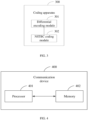
- an embodiment of this application provides a coding apparatus 300, including:
- a DSTBC scheme, an NSTBC codebook, and a power sum of transmit symbols on a transmit antenna in previous two symbol periods are used to calculate a transmit symbol for a current symbol period, and additionally, the NSTBC codebook with low complexity is used to calculate a transmit symbol for a next symbol period.
- the NSTBC codebook can help to reduce the number of load impedance types on the antenna while ensuring diversity gain, reduce the complexity of system implementation, and effectively reduce the probability of detection errors.
- the codebook structure of the NSTBC codebook satisfies: s 2 t + 1 s 2 t + 2 * s 2 t + 2 ⁇ s 2 t + 1 * , where s 2t+i and s 2 t + 2 * are transmit symbols on two transmit antennas obtained by the coding end from coding in the (2t+1)-th symbol period; and s 2t+2 and ⁇ s 2 t + 1 * are transmit symbols on two transmit antennas obtained by the coding end from coding in the (2t+2)-th symbol period; where the symbol s 2 t + 2 * is the conjugate of the symbol s 2t+2 , and the symbol ⁇ s 2t + 1 ⁇ is the negative conjugate of the symbol s 2t+1 ; and the (2t+1)-th symbol period is the current symbol period, and the (2t+2)-th symbol period is a symbol period next to the current symbol period.
- the differential coding module and the NSTBC coding module are specifically configured for the coding end to:
- the differential coding module is specifically configured for the coding end to:
- the differential coding module is specifically configured for the coding end to:
- the differential coding module is specifically configured for the coding end to:
- the differential coding module is specifically further configured for the coding end to:
- the differential coding module may be specifically further configured for the coding end to:
- the differential coding module is specifically further configured for the coding end to:
- the NSTBC coding module is specifically configured to:
- the apparatus further includes:
- a mapping relationship is present between the original bits for the current symbol period and the transmit symbol for the current symbol period.
- the NSTBC codebook is used for space-time block coding, or the NSTBC codebook is used for polarization-time block coding, that is, two transmit antennas can be isolated spatially or in polarization.
- the transmit symbols are constant modulation symbols or nonconstant modulation symbols.
- the constant modulation at least includes BPSK modulation.
- the nonconstant modulation at least includes APSK modulation.
- the coding apparatus in this embodiment of this application may be an electronic device such as an electronic device with an operating system, or a component in an electronic device such as an integrated circuit or chip.
- the electronic device may be a terminal or a device other than terminals.
- the terminal may include but is not limited to the types of the terminal listed above, and the other devices may be servers, network attached storage (Network Attached Storage, NAS), or the like, which are not specifically limited in this embodiment of this application.
- NAS Network Attached Storage
- the coding apparatus provided in this embodiment of this application can implement the processes implemented in the method embodiment in FIG. 2 , with the same technical effects achieved. To avoid repetition, details are not repeated herein.
- an embodiment of this application further provides a communication device 400 including a processor 401 and a memory 402.
- the memory 402 has stored thereon a program or instructions capable of running on the processor 401.
- the communication device 400 is a terminal, when the program or instructions are executed by the processor 401, the steps of the foregoing embodiment of the coding method are implemented, with the same technical effects achieved. To avoid repetition, details are not repeated herein.
- the communication device 400 is a network-side device, the program or instructions are executed by the processor 401 to implement the steps of the foregoing embodiment of the coding method, with the same technical effects achieved. To avoid repetition, details are not repeated herein.
- a DSTBC scheme, an NSTBC codebook, and a power sum of transmit symbols on a transmit antenna in previous two symbol periods are used to calculate a transmit symbol for a current symbol period, and additionally, the NSTBC codebook with low complexity is used to calculate a transmit symbol for a next symbol period.
- the NSTBC codebook can help to reduce the number of load impedance types on the antenna while ensuring diversity gain, reduce the complexity of system implementation, and effectively reduce the probability of detection errors.
- FIG. 5 is a schematic diagram of a hardware structure of a terminal implementing embodiments of this application.
- the terminal 500 includes but is not limited to at least part of these components: a radio frequency unit 501, a network module 502, an audio output unit 503, an input unit 504, a sensor 505, a display unit 506, a user input unit 507, an interface unit 508, a memory 509, a processor 510, and the like.
- the terminal 500 may further include a power supply (for example, battery) supplying power to the components.
- the power supply may be logically connected to the processor 510 via a power management system, so that functions such as charge management, discharge management, and power consumption management are implemented via the power management system.
- the structure of the terminal shown in FIG. 5 does not constitute any limitation on the terminal, and the terminal may include more or fewer components than shown in the figure, or combine some of the components, or have different arrangements of the components. Details are not described herein.
- the input unit 504 may include a graphics processing unit (Graphics Processing Unit, GPU) 5041 and a microphone 5042.
- the graphics processing unit 5041 processes image data of a static picture or video obtained by an image capture apparatus (such as a camera) in an image capture or video capture mode.
- the display unit 506 may include a display panel 5061.
- the display panel 5061 may be configured in a form of a liquid crystal display, an organic light-emitting diode display, or the like.
- the user input unit 507 includes at least one of a touch panel 5071 and other input devices 5072.
- the touch panel 5071 is also referred to as a touchscreen.
- the touch panel 5071 may include two parts: a touch detection apparatus and a touch controller.
- the other input devices 5072 may include but are not limited to a physical keyboard, a function button (for example, volume control button or on/off button), a trackball, a mouse, and a joystick. Details are not described herein.
- the radio frequency unit 501 receives downlink data from a network-side device and transfers the data to the processor 510 for processing; and the radio frequency unit 501 can additionally send uplink data to the network-side device.
- the radio frequency unit 501 includes but is not limited to an antenna, an amplifier, a transceiver, a coupler, a low noise amplifier, a duplexer, and the like.
- the memory 509 may be configured to store software programs or instructions and various data.
- the memory 509 may include a first storage area for storing programs or instructions and a second storage area for storing data.
- the first storage area may store an operating system, an application program or instructions required by at least one function (for example, a sound playback function or an image playback function), and the like.
- the memory 509 may be a volatile memory or a non-volatile memory, or the memory 509 may include both a volatile memory and a non-volatile memory.
- the non-volatile memory may be a read-only memory (Read-Only Memory, ROM), a programmable read-only memory (Programmable ROM, PROM), an erasable programmable read-only memory (Erasable PROM, EPROM), an electrically erasable programmable read-only memory (Electrically EPROM, EEPROM), or a flash memory.
- ROM Read-Only Memory
- PROM programmable read-only memory
- Erasable PROM Erasable PROM
- EPROM electrically erasable programmable read-only memory
- EEPROM electrically erasable programmable read-only memory
- the volatile memory may be a random access memory (Random Access Memory, RAM), a static random access memory (Static RAM, SRAM), a dynamic random access memory (Dynamic RAM, DRAM), a synchronous dynamic random access memory (Synchronous DRAM, SDRAM), a double data rate synchronous dynamic random access memory (Double Data Rate SDRAM, DDRSDRAM), an enhanced synchronous dynamic random access memory (Enhanced SDRAM, ESDRAM), a synchronous link dynamic random access memory (Synch link DRAM, SLDRAM), and a direct rambus random access memory (Direct Rambus RAM, DRRAM).
- RAM Random Access Memory
- SRAM static random access memory
- DRAM dynamic random access memory
- DRAM synchronous dynamic random access memory
- SDRAM double data rate synchronous dynamic random access memory
- Enhanced SDRAM, ESDRAM enhanced synchronous dynamic random access memory
- Synch link DRAM, SLDRAM synchronous link dynamic random access memory
- Direct Rambus RAM Direct Rambus RAM
- the processor 510 may include one or more processing units.
- the processor 510 may integrate an application processor and a modem processor.
- the application processor primarily processes operations involving an operating system, user interface, application program, or the like.
- the modem processor primarily processes radio communication signals, for example, being a baseband processor. It can be understood that the modem processor may be alternatively not integrated in the processor 510.
- the processor 510 is configured for a coding end to perform coding through a differential space time block coding DSTBC scheme, a new space time block coding NSTBC codebook, and a power sum of transmit symbols on a transmit antenna in previous two symbol periods to obtain a transmit symbol for a current symbol period.
- the processor 510 is configured for a coding end to determine a transmit symbol for a symbol period next to the current symbol period based on the transmit symbol for the current symbol period and the NSTBC codebook, where the previous two symbol periods are two adjacent symbol periods preceding the current symbol period.
- a DSTBC scheme, an NSTBC codebook, and a power sum of transmit symbols on a transmit antenna in previous two symbol periods are used to calculate a transmit symbol for a current symbol period, and additionally, the NSTBC codebook with low complexity is used to calculate a transmit symbol for a next symbol period.
- the NSTBC codebook can help to reduce the number of load impedance types on the antenna while ensuring diversity gain, reduce the complexity of system implementation, and effectively reduce the probability of detection errors.
- a codebook structure of the NSTBC codebook satisfies: s 2 t + 1 s 2 t + 2 * s 2 t + 2 ⁇ s 2 t + 1 * , where s 2t+i and s 2 t + 2 * are transmit symbols on two transmit antennas obtained by the coding end from coding in the (2t+1)-th symbol period; and s 2t+2 and ⁇ s 2 t + 1 * are transmit symbols on two transmit antennas obtained by the coding end from coding in the (2t+2)-th symbol period; where the symbol s 2 t + 2 * is the conjugate of the symbol s 2t+2 , and the symbol ⁇ s 2 t + 1 * is the negative conjugate of the symbol s 2t+1 ; and the (2t+1)-th symbol period is the current symbol period, and the (2t+2)-th symbol period is a symbol period next to the current symbol period.
- the processor 510 is configured for the coding end to:
- the processor 510 is configured for the coding end to:
- the processor 510 is configured for the coding end to:
- the processor 510 is configured for the coding end to:
- the processor 510 may be further configured for the coding end to:
- the processor 510 may be further configured for the coding end to:
- the processor 510 may be further configured for the coding end to:
- the processor 510 is specifically configured for the coding end to:
- mapping relationship is present between the original bits for the current symbol period and an amplitude of the transmit symbol for the current symbol period.
- the NSTBC codebook is used for space-time block coding, or the NSTBC codebook is used for polarization-time block coding.
- the transmit symbols are constant modulation symbols or nonconstant modulation symbols.
- the constant modulation at least includes BPSK modulation.
- the nonconstant modulation at least includes APSK modulation.
- the network-side device 600 includes an antenna 61, a radio frequency apparatus 62, a baseband apparatus 63, a processor 64, and a memory 65.
- the antenna 61 is connected to the radio frequency apparatus 62.
- the radio frequency apparatus 62 receives information through the antenna 61, and sends the received information to the baseband apparatus 63 for processing.
- the baseband apparatus 63 processes to-be-sent information, and sends the information to the radio frequency apparatus 62; and the radio frequency apparatus 62 processes the received information and then sends the information out through the antenna 61.
- the method in the foregoing method embodiment may be implemented on the baseband apparatus 63.
- the baseband apparatus 63 includes a baseband processor.
- the baseband apparatus 63 may include, for example, at least one baseband processing unit, where a plurality of chips are disposed on the baseband processing unit. As shown in FIG. 6 , one of the chips is, for example, a baseband processor, and connected to the memory 65 through a bus interface, to invoke the program in the memory 65 to perform the operations of the network-side device shown in the foregoing method embodiment.
- the network-side device may further include a network interface 66, where the interface is, for example, a common public radio interface (Common Public Radio Interface, CPRI).
- CPRI Common Public Radio Interface
- the network-side device 600 in this embodiment of the present invention further includes: an instruction or program stored in the memory 65 and capable of running on the processor 64.
- the processor 64 invokes the instruction or program in the memory 65 to execute the method executed by the modules shown in FIG. 3 , with the same technical effects achieved. To avoid repetition, details are not repeated herein.
- An embodiment of this application further provides a readable storage medium.
- the readable storage medium has stored thereon a program or instructions, and when the program or instructions are executed by a processor, the processes of the foregoing embodiment of the coding method are implemented, with the same technical effects achieved. To avoid repetition, details are not repeated herein.
- the processor is a processor in the terminal in the foregoing embodiment.
- the readable storage medium includes a computer-readable storage medium such as a computer read-only memory ROM, a random access memory RAM, a magnetic disk, or an optical disc.
- the chip includes a processor and a communication interface, the communication interface is coupled to the processor, and the processor is configured to run a program or instructions to implement the processes of the foregoing embodiment of the coding method, with the same technical effects achieved. To avoid repetition, details are not repeated herein.
- the chip mentioned in this embodiment of this application may also be referred to as a system-level chip, a system chip, a chip system, a system-on-chip, or the like.
- An embodiment of this application further provides a computer program product, where the computer program product is stored in a storage medium.
- the computer program product is executed by at least one processor, the processes of the foregoing embodiment of the coding method are implemented, with the same technical effects achieved. To avoid repetition, details are not repeated herein.
- An embodiment of this application further provides a communication device.
- the communication device is configured to implement the processes of the foregoing embodiment of the coding method, with the same technical effects achieved. To avoid repetition, details are not repeated herein.
- the computer software product is stored in a storage medium (for example, a ROM/RAM, a magnetic disk, or an optical disc), and includes several instructions for instructing a terminal (which may be a mobile phone, a computer, a server, an air conditioner, a network device, or the like) to perform the method described in the embodiments of this application.
- a storage medium for example, a ROM/RAM, a magnetic disk, or an optical disc
Landscapes
- Engineering & Computer Science (AREA)
- Signal Processing (AREA)
- Computer Networks & Wireless Communication (AREA)
- Radio Transmission System (AREA)
- Mobile Radio Communication Systems (AREA)
Applications Claiming Priority (2)
| Application Number | Priority Date | Filing Date | Title |
|---|---|---|---|
| CN202210056640.9A CN116506084B (zh) | 2022-01-18 | 2022-01-18 | 编码方法、设备及可读存储介质 |
| PCT/CN2023/071802 WO2023138458A1 (zh) | 2022-01-18 | 2023-01-11 | 编码方法、设备及可读存储介质 |
Publications (2)
| Publication Number | Publication Date |
|---|---|
| EP4468637A1 true EP4468637A1 (de) | 2024-11-27 |
| EP4468637A4 EP4468637A4 (de) | 2025-04-30 |
Family
ID=87329040
Family Applications (1)
| Application Number | Title | Priority Date | Filing Date |
|---|---|---|---|
| EP23742773.7A Pending EP4468637A4 (de) | 2022-01-18 | 2023-01-11 | Codierungsverfahren, vorrichtung und lesbares speichermedium |
Country Status (5)
| Country | Link |
|---|---|
| US (1) | US20240372650A1 (de) |
| EP (1) | EP4468637A4 (de) |
| JP (1) | JP2025503002A (de) |
| CN (1) | CN116506084B (de) |
| WO (1) | WO2023138458A1 (de) |
Families Citing this family (1)
| Publication number | Priority date | Publication date | Assignee | Title |
|---|---|---|---|---|
| CN116418998B (zh) * | 2021-12-30 | 2025-09-23 | 维沃移动通信有限公司 | 解码方法、设备及可读存储介质 |
Family Cites Families (9)
| Publication number | Priority date | Publication date | Assignee | Title |
|---|---|---|---|---|
| DE102005040067B4 (de) * | 2005-08-24 | 2007-08-30 | Siemens Ag | Verfahren Sendevorrichtung und Empfangsvorrichtung zum Kodieren von Daten mit einem differenziellen Raum-Zeit-Blockkode |
| KR100967954B1 (ko) * | 2008-07-10 | 2010-07-06 | 한국전자통신연구원 | 유사 직교 시공간 블록 부호 시스템 및 방법 |
| US8553794B2 (en) * | 2009-04-06 | 2013-10-08 | Intel Corporation | Full-rate, full-diversity space-time block code technique for multiple transmissions using simple linear decoding complexity |
| JP6240462B2 (ja) * | 2013-10-15 | 2017-11-29 | 日本放送協会 | 送信システム |
| GB2557208A (en) * | 2016-11-30 | 2018-06-20 | Univ Of Kwazulu Natal Ip And Technology Tansfer Office | Communication method, apparatus and system |
| CN108880644B (zh) * | 2017-07-26 | 2019-06-11 | 华为技术有限公司 | 用于数据传输的方法、装置和系统 |
| WO2020026450A1 (ja) * | 2018-08-03 | 2020-02-06 | 株式会社Nttドコモ | ユーザ端末 |
| CN111586874B (zh) * | 2019-02-15 | 2022-11-25 | 华为技术有限公司 | 一种天线参数调整的方法以及相关装置 |
| US20210204303A1 (en) * | 2019-12-26 | 2021-07-01 | Vinod Kristem | Transmit power allocation and modulation coding scheme for multi-user orthogonal frequency-division multiple access |
-
2022
- 2022-01-18 CN CN202210056640.9A patent/CN116506084B/zh active Active
-
2023
- 2023-01-11 EP EP23742773.7A patent/EP4468637A4/de active Pending
- 2023-01-11 WO PCT/CN2023/071802 patent/WO2023138458A1/zh not_active Ceased
- 2023-01-11 JP JP2024542926A patent/JP2025503002A/ja active Pending
-
2024
- 2024-07-17 US US18/775,121 patent/US20240372650A1/en active Pending
Also Published As
| Publication number | Publication date |
|---|---|
| JP2025503002A (ja) | 2025-01-30 |
| US20240372650A1 (en) | 2024-11-07 |
| CN116506084A (zh) | 2023-07-28 |
| CN116506084B (zh) | 2025-11-14 |
| WO2023138458A1 (zh) | 2023-07-27 |
| EP4468637A4 (de) | 2025-04-30 |
Similar Documents
| Publication | Publication Date | Title |
|---|---|---|
| US9974081B2 (en) | Method of power allocation and base station using the same | |
| US20220191853A1 (en) | Identifying a beam in 5g wireless communication systems | |
| US20240388382A1 (en) | Encoding method, device, and readable storage medium | |
| US20170085358A1 (en) | System and Method for Multiple-Input and Multiple-Output (MIMO) Full-Duplex Precoding Algorithms | |
| US20150146565A1 (en) | Method and apparatus for downlink transmission in a cloud radio access network | |
| CN118383000A (zh) | 用于提高通信系统中的数据接收性能的方法和装置 | |
| US20240372650A1 (en) | Coding method and apparatus and readable storage medium | |
| US20240340104A1 (en) | Encoding method and apparatus, and readable storage medium | |
| US20250343655A1 (en) | Phase tracking reference signal transmission method and apparatus, terminal, and network-side device | |
| US12562783B2 (en) | Diversity transmission method, terminal, and network-side device | |
| US20240305402A1 (en) | Method and apparatus for performing signal compensation based on frequency resource allocation | |
| US12494826B2 (en) | Decoding method, device, and readable storage medium | |
| US11483039B2 (en) | Method and apparatus for detecting signal with quantum computing in MIMO system | |
| US20130083863A1 (en) | Apparatus and method for low complexity feedback in a mimo wireless network | |
| US11863353B2 (en) | Anchor process of data symbols in channel estimation | |
| WO2023138459A1 (zh) | 解码方法、设备及可读存储介质 | |
| US12597982B2 (en) | Determining error vector magnitude for a single layer transmission using a multiple-input multiple-output receiver | |
| US20260031867A1 (en) | Information processing method, information processing apparatus, terminal and network side device | |
| US20250337466A1 (en) | Artificial intelligence aided carrier aggregation | |
| US20250202748A1 (en) | Reference signals for log-likelihood ratio scaling estimation for pre-equalized transmissions | |
| WO2025007845A1 (zh) | 编码方法、解码方法、装置及通信设备 |
Legal Events
| Date | Code | Title | Description |
|---|---|---|---|
| STAA | Information on the status of an ep patent application or granted ep patent |
Free format text: STATUS: THE INTERNATIONAL PUBLICATION HAS BEEN MADE |
|
| PUAI | Public reference made under article 153(3) epc to a published international application that has entered the european phase |
Free format text: ORIGINAL CODE: 0009012 |
|
| STAA | Information on the status of an ep patent application or granted ep patent |
Free format text: STATUS: REQUEST FOR EXAMINATION WAS MADE |
|
| 17P | Request for examination filed |
Effective date: 20240806 |
|
| AK | Designated contracting states |
Kind code of ref document: A1 Designated state(s): AL AT BE BG CH CY CZ DE DK EE ES FI FR GB GR HR HU IE IS IT LI LT LU LV MC ME MK MT NL NO PL PT RO RS SE SI SK SM TR |
|
| REG | Reference to a national code |
Ref country code: DE Ref legal event code: R079 Free format text: PREVIOUS MAIN CLASS: H04L0005000000 Ipc: H04L0001060000 |
|
| DAV | Request for validation of the european patent (deleted) | ||
| DAX | Request for extension of the european patent (deleted) | ||
| A4 | Supplementary search report drawn up and despatched |
Effective date: 20250328 |
|
| RIC1 | Information provided on ipc code assigned before grant |
Ipc: H04B 7/06 20060101ALI20250324BHEP Ipc: H04B 7/02 20180101ALI20250324BHEP Ipc: H04L 1/06 20060101AFI20250324BHEP |