EP4468482A1 - Batterieträger - Google Patents
Batterieträger Download PDFInfo
- Publication number
- EP4468482A1 EP4468482A1 EP23175118.1A EP23175118A EP4468482A1 EP 4468482 A1 EP4468482 A1 EP 4468482A1 EP 23175118 A EP23175118 A EP 23175118A EP 4468482 A1 EP4468482 A1 EP 4468482A1
- Authority
- EP
- European Patent Office
- Prior art keywords
- joining
- battery carrier
- profile
- carrier according
- leg
- Prior art date
- Legal status (The legal status is an assumption and is not a legal conclusion. Google has not performed a legal analysis and makes no representation as to the accuracy of the status listed.)
- Granted
Links
Images


Classifications
-
- H—ELECTRICITY
- H01—ELECTRIC ELEMENTS
- H01M—PROCESSES OR MEANS, e.g. BATTERIES, FOR THE DIRECT CONVERSION OF CHEMICAL ENERGY INTO ELECTRICAL ENERGY
- H01M50/00—Constructional details or processes of manufacture of the non-active parts of electrochemical cells other than fuel cells, e.g. hybrid cells
- H01M50/20—Mountings; Secondary casings or frames; Racks, modules or packs; Suspension devices; Shock absorbers; Transport or carrying devices; Holders
- H01M50/244—Secondary casings; Racks; Suspension devices; Carrying devices; Holders characterised by their mounting method
-
- B—PERFORMING OPERATIONS; TRANSPORTING
- B60—VEHICLES IN GENERAL
- B60K—ARRANGEMENT OR MOUNTING OF PROPULSION UNITS OR OF TRANSMISSIONS IN VEHICLES; ARRANGEMENT OR MOUNTING OF PLURAL DIVERSE PRIME-MOVERS IN VEHICLES; AUXILIARY DRIVES FOR VEHICLES; INSTRUMENTATION OR DASHBOARDS FOR VEHICLES; ARRANGEMENTS IN CONNECTION WITH COOLING, AIR INTAKE, GAS EXHAUST OR FUEL SUPPLY OF PROPULSION UNITS IN VEHICLES
- B60K1/00—Arrangement or mounting of electrical propulsion units
- B60K1/04—Arrangement or mounting of electrical propulsion units of the electric storage means for propulsion
-
- B—PERFORMING OPERATIONS; TRANSPORTING
- B60—VEHICLES IN GENERAL
- B60L—PROPULSION OF ELECTRICALLY-PROPELLED VEHICLES; SUPPLYING ELECTRIC POWER FOR AUXILIARY EQUIPMENT OF ELECTRICALLY-PROPELLED VEHICLES; ELECTRODYNAMIC BRAKE SYSTEMS FOR VEHICLES IN GENERAL; MAGNETIC SUSPENSION OR LEVITATION FOR VEHICLES; MONITORING OPERATING VARIABLES OF ELECTRICALLY-PROPELLED VEHICLES; ELECTRIC SAFETY DEVICES FOR ELECTRICALLY-PROPELLED VEHICLES
- B60L50/00—Electric propulsion with power supplied within the vehicle
- B60L50/50—Electric propulsion with power supplied within the vehicle using propulsion power supplied by batteries or fuel cells
- B60L50/60—Electric propulsion with power supplied within the vehicle using propulsion power supplied by batteries or fuel cells using power supplied by batteries
- B60L50/64—Constructional details of batteries specially adapted for electric vehicles
-
- B—PERFORMING OPERATIONS; TRANSPORTING
- B60—VEHICLES IN GENERAL
- B60L—PROPULSION OF ELECTRICALLY-PROPELLED VEHICLES; SUPPLYING ELECTRIC POWER FOR AUXILIARY EQUIPMENT OF ELECTRICALLY-PROPELLED VEHICLES; ELECTRODYNAMIC BRAKE SYSTEMS FOR VEHICLES IN GENERAL; MAGNETIC SUSPENSION OR LEVITATION FOR VEHICLES; MONITORING OPERATING VARIABLES OF ELECTRICALLY-PROPELLED VEHICLES; ELECTRIC SAFETY DEVICES FOR ELECTRICALLY-PROPELLED VEHICLES
- B60L50/00—Electric propulsion with power supplied within the vehicle
- B60L50/50—Electric propulsion with power supplied within the vehicle using propulsion power supplied by batteries or fuel cells
- B60L50/60—Electric propulsion with power supplied within the vehicle using propulsion power supplied by batteries or fuel cells using power supplied by batteries
- B60L50/66—Arrangements of batteries
-
- H—ELECTRICITY
- H01—ELECTRIC ELEMENTS
- H01M—PROCESSES OR MEANS, e.g. BATTERIES, FOR THE DIRECT CONVERSION OF CHEMICAL ENERGY INTO ELECTRICAL ENERGY
- H01M50/00—Constructional details or processes of manufacture of the non-active parts of electrochemical cells other than fuel cells, e.g. hybrid cells
- H01M50/20—Mountings; Secondary casings or frames; Racks, modules or packs; Suspension devices; Shock absorbers; Transport or carrying devices; Holders
- H01M50/233—Mountings; Secondary casings or frames; Racks, modules or packs; Suspension devices; Shock absorbers; Transport or carrying devices; Holders characterised by physical properties of casings or racks, e.g. dimensions
- H01M50/242—Mountings; Secondary casings or frames; Racks, modules or packs; Suspension devices; Shock absorbers; Transport or carrying devices; Holders characterised by physical properties of casings or racks, e.g. dimensions adapted for protecting batteries against vibrations, collision impact or swelling
-
- H—ELECTRICITY
- H01—ELECTRIC ELEMENTS
- H01M—PROCESSES OR MEANS, e.g. BATTERIES, FOR THE DIRECT CONVERSION OF CHEMICAL ENERGY INTO ELECTRICAL ENERGY
- H01M50/00—Constructional details or processes of manufacture of the non-active parts of electrochemical cells other than fuel cells, e.g. hybrid cells
- H01M50/20—Mountings; Secondary casings or frames; Racks, modules or packs; Suspension devices; Shock absorbers; Transport or carrying devices; Holders
- H01M50/249—Mountings; Secondary casings or frames; Racks, modules or packs; Suspension devices; Shock absorbers; Transport or carrying devices; Holders specially adapted for aircraft or vehicles, e.g. cars or trains
-
- B—PERFORMING OPERATIONS; TRANSPORTING
- B60—VEHICLES IN GENERAL
- B60K—ARRANGEMENT OR MOUNTING OF PROPULSION UNITS OR OF TRANSMISSIONS IN VEHICLES; ARRANGEMENT OR MOUNTING OF PLURAL DIVERSE PRIME-MOVERS IN VEHICLES; AUXILIARY DRIVES FOR VEHICLES; INSTRUMENTATION OR DASHBOARDS FOR VEHICLES; ARRANGEMENTS IN CONNECTION WITH COOLING, AIR INTAKE, GAS EXHAUST OR FUEL SUPPLY OF PROPULSION UNITS IN VEHICLES
- B60K1/00—Arrangement or mounting of electrical propulsion units
- B60K1/04—Arrangement or mounting of electrical propulsion units of the electric storage means for propulsion
- B60K2001/0405—Arrangement or mounting of electrical propulsion units of the electric storage means for propulsion characterised by their position
- B60K2001/0438—Arrangement under the floor
-
- H—ELECTRICITY
- H01—ELECTRIC ELEMENTS
- H01M—PROCESSES OR MEANS, e.g. BATTERIES, FOR THE DIRECT CONVERSION OF CHEMICAL ENERGY INTO ELECTRICAL ENERGY
- H01M2220/00—Batteries for particular applications
- H01M2220/20—Batteries in motive systems, e.g. vehicle, ship, plane
-
- H—ELECTRICITY
- H01—ELECTRIC ELEMENTS
- H01M—PROCESSES OR MEANS, e.g. BATTERIES, FOR THE DIRECT CONVERSION OF CHEMICAL ENERGY INTO ELECTRICAL ENERGY
- H01M50/00—Constructional details or processes of manufacture of the non-active parts of electrochemical cells other than fuel cells, e.g. hybrid cells
- H01M50/20—Mountings; Secondary casings or frames; Racks, modules or packs; Suspension devices; Shock absorbers; Transport or carrying devices; Holders
- H01M50/262—Mountings; Secondary casings or frames; Racks, modules or packs; Suspension devices; Shock absorbers; Transport or carrying devices; Holders with fastening means, e.g. locks
-
- Y—GENERAL TAGGING OF NEW TECHNOLOGICAL DEVELOPMENTS; GENERAL TAGGING OF CROSS-SECTIONAL TECHNOLOGIES SPANNING OVER SEVERAL SECTIONS OF THE IPC; TECHNICAL SUBJECTS COVERED BY FORMER USPC CROSS-REFERENCE ART COLLECTIONS [XRACs] AND DIGESTS
- Y02—TECHNOLOGIES OR APPLICATIONS FOR MITIGATION OR ADAPTATION AGAINST CLIMATE CHANGE
- Y02E—REDUCTION OF GREENHOUSE GAS [GHG] EMISSIONS, RELATED TO ENERGY GENERATION, TRANSMISSION OR DISTRIBUTION
- Y02E60/00—Enabling technologies; Technologies with a potential or indirect contribution to GHG emissions mitigation
- Y02E60/10—Energy storage using batteries
Definitions
- the invention relates to a battery carrier according to the features in the preamble of claim 1.
- Battery carriers are used to hold battery elements for providing electrical energy in electrically powered vehicles. These are arranged between the vehicle's axles.
- One of the key safety requirements for a battery carrier is good crash performance. To meet these requirements, the battery tray is protected by an external reinforcement structure.
- the battery carrier for an electric vehicle is state of the art.
- the battery carrier has a battery tray that is inserted into an outer frame and closed by a lid.
- the frame is made of at least two profile components joined together in cross-section wherein at least one of these profile components is manufactured as a sheet metal formed component.
- the battery tray is protected by a frame structure with a hollow chamber that surrounds it on the outside.
- the DE 10 2018 120 371 B4 discloses a battery carrier with an external reinforcement by a frame structure which is composed of several hollow chamber profile parts connected to one another in the region of their ends.
- the WO 2018/166895 A1 a battery carrier for receiving battery elements with a frame forming an inner region which at least partially provides side walls of the battery carrier and a reinforcing structure which comprises one or more reinforcing profiles.
- the battery carriers must be mechanically stable and attached to the body or chassis of a vehicle.
- the battery tray should be integrated into the body as much as possible, which presents design and assembly challenges.
- the invention is based on the object of creating a battery carrier with improved functionality and crash performance.
- a battery carrier for holding battery elements for the provision of electrical energy in electrically powered vehicles has a battery tray with a reinforcing structure which is arranged on the outside in front of at least one side wall of the battery tray.
- the reinforcement structure comprises an inner profile and an outer profile.
- the inner profile is U-shaped in cross-section and has a web and two legs as well as an opening.
- the web is oriented parallel to the side wall.
- the legs of the inner profile point away from the battery tray so that the open side of the inner profile is on the outside.
- the open side or the opening of the inner profile is closed at least in length sections by the outer profile.
- the inner profile is easily accessible via the opening and the open side of the inner profile facing outwards away from the battery tray. This improves the functionality, in particular the accessibility and assembly of the inner profile itself as well as the components to be mounted in the inner profile.
- the inner profile and the outer profile complement each other synergistically.
- the reinforcement structure extends in the longitudinal direction of the side wall.
- the inner profile and the outer profile form a box-shaped hollow profile at least over the majority of the length of the reinforcement structure. This is characterized by advantageous static and dynamic load behavior.
- the rigidity of the reinforcement structure transverse to the battery tray is improved.
- the legs of the inner profile can deform while dissipating energy, with the outer profile acting as a tension strut and still holding the legs in position relative to each other.
- Closed in length sections means that the opening of the inner profile can be closed by an outer profile over the entire length of the inner profile.
- the outer profile can also close the opening over only a length section of the inner profile.
- Several outer profiles can also be provided which close the opening of the inner profile over at least the majority of the length.
- An outer profile can also be perforated, in particular to save weight, or be provided with holes and recesses.
- the outer profile can have oval or rectangular holes or recesses. Rectangular holes or recesses in particular have rounded corner areas. Such oval or rectangular holes or recesses designed as elongated holes preferably have dimensions between 20 x 80 mm and 60 x 80 mm.
- Holes or recesses in the outer profile can also be used to join the reinforcement structure to the side wall of the battery tray.
- At least one sleeve is provided in the reinforcement structure.
- These are fastening or assembly sleeves.
- several sleeves are provided in the longitudinal direction of the reinforcement structure, arranged at a distance from one another.
- a sleeve extends between the legs of the inner profile over the entire height of the inner profile.
- the sleeve connects openings in the legs.
- the sleeves are oriented coaxially to the openings.
- the sleeve and opening lie on a common longitudinal axis.
- the sleeves are used to carry fastening means, by means of which the battery carrier is fixed in the body or chassis of a vehicle.
- the battery carrier is fixed to side sills and, if necessary, floor cross members in the motor vehicle using the sleeves and suitable fastening means.
- the sleeves have an upper and/or a lower collar.
- a collar is oriented outwards from the sleeve body.
- the collar can be a uniform component of the sleeve or be formed by a separate collar body.
- the collars absorb the friction and pressure forces that arise when tightening assembly elements guided through the sleeves, for example screw connection elements. This can protect the surface of the components in the area of a screw connection from damage and reduce the surface pressure. In particular, the collars ensure tolerance compensation.
- the flat collar surface is larger than the sleeve surface, so that the sleeves or their sleeve bodies can be aligned or positioned horizontally before welding to the inner profile. The alignment takes place according to the defined lateral sill hole distances.
- a sleeve or the sleeve body of a sleeve can be made up of several parts.
- a sleeve can be made up of two parts, i.e. two sleeve body parts.
- the two sleeve body parts are joined together during assembly in the reinforcement structure.
- a two-part sleeve has two sleeve body parts.
- a sleeve body part is guided from the outside through an opening in a leg so that the collars rest on the outside of the inner legs.
- the sleeves are then joined to the inner profile in the area of the collars.
- the two sleeve body parts are then brought together inside the inner profile and joined together. This can be done with a force fit and/or a form fit.
- the two sleeve body parts can be joined by a toothing or a press fit.
- a bayonet-type connection is also possible.
- a two-part sleeve is advantageous in terms of assembly.
- One sleeve body part is guided through an upper or lower leg opening and connected in a partially overlapping manner, in particular by means of a press fit.
- the sleeves are welded to the inner profile or the legs of the inner profile via the collars.
- a sleeve can also be formed by an inner sleeve and an outer sleeve.
- Joining tabs are provided at the end of the legs of the inner profile.
- several joining tabs are provided in the longitudinal direction of the inner profile, spaced apart from one another, along the longitudinal edge sections of the legs.
- the joining tabs protrude outwards.
- an alternating row of joining tabs is provided on each leg along its longitudinal edge section. The joining tabs are spaced apart from one another in the longitudinal direction of a leg, so that there is free space between the joining tabs.
- the outer profile is supported on the free ends or the longitudinal edge sections of the legs and/or on the joining tabs of the legs.
- a joining lug is set at an angle to a leg.
- the joining lugs are angled outwards from the free end of the legs This improves accessibility, especially for the production of spot welds. The required installation space on the outside is also reduced.
- the outer profile has joining webs that are supported on the legs of the inner profile.
- the outer profile with joining webs rests on the joining tabs in some areas.
- the outer profile is firmly connected to the inner profile. This is achieved by a firm bond between the joining tabs of the inner profile and the joining webs of the outer profile.
- the firm bond between the joining tabs and the joining web is achieved by a spot weld or spot weld bonding.
- a further advantageous embodiment provides that upper and lower joining tabs are provided.
- An upper tab is located at the end of the upper leg of the inner profile.
- a lower joining tab is located at the end of the free end of the lower leg of the inner profile.
- the upper joining tab and the lower joining tab are each oriented outwards at an angle from the associated upper leg or lower leg.
- the upper joining tab and the lower joining tab are directed away from each other.
- the upper joining tabs and the lower joining tabs are arranged in relation to one another at a tab opening angle.
- the tab opening angle can be between greater than or equal to ( ⁇ ) 45° and less than or equal to ( ⁇ ) 240°.
- the tab opening angle is preferably in a range between 80° and 150° inclusive. In particular, the tab opening angle is between 60° and 120° inclusive.
- the joining tabs on the inner profile and the joining webs on the outer profile are contour-matched to each other and complement each other. It is particularly advantageous if the joining tabs and the joining webs are set at the same angle and aligned to complement each other.
- Built-in elements could be load-guiding bodies, bulkhead plates and similar internal reinforcement and/or functional components.
- the reinforcement structure is connected to the battery tray.
- the inner profile is joined to the battery tray.
- the inner profile is joined with its rear web against a side wall of the battery tray.
- the open inner profile is advantageously accessible from the side.
- the sleeves and other installation elements can be inserted and mounted in the open inner profile.
- the inner profile is then closed by one or more outer profiles.
- the or each outer profile is connected to the upper leg and the lower leg and acts as a tensile load strut between the legs, which counteracts the spreading of the inner profile in the event of a side impact.
- Cutouts or recesses are provided between the joining tabs on the legs of the inner profile.
- the contour of the legs can also be adapted to the connection to the joining surfaces.
- one design provides for the inner profile to be embossed or recessed in some areas in the area of an installation element and/or in the area of a sleeve.
- reinforcement or stiffening elements can also be integrated into the battery tray.
- Such reinforcement or stiffening elements can be formed by longitudinal and/or transverse profiles or struts that extend along the tray floor.
- a cover can form the upper end of the battery tray.
- the battery carrier is particularly advantageously designed and intended to be integrated into the body or chassis of a vehicle.
- the battery carrier forms a load-bearing part of the body (cell-to-body).
- the floor of the vehicle can form the battery cover.
- the battery tray is a one-piece deep-drawn part made from the same material.
- the inner profile and the outer profile can also be manufactured using press molding or deep-drawing technology. Due to its U-shaped cross section, the inner profile has a channel-like course in which several sleeves are arranged at a distance from one another in the longitudinal direction.
- the at least one outer profile closes the inner profile like a locking plate over at least part of its length.
- Several outer profiles can be provided in the longitudinal direction of the reinforcement structure. The one outer profile or the several outer profiles form the outer wall of the reinforcement structure.
- the battery tray can also be folded from a sheet metal plate to form the battery tray.
- a sheet metal plate is provided whose geometry corresponds to the unfolding of the battery tray.
- a cooling plate can optionally be joined directly to the sheet metal plate before it is then folded to form the battery tray.
- the battery tray is designed as a folding component. The folding corners of the battery tray are joined and sealed.
- the battery tray as well as the reinforcement structure and the components forming the reinforcement structure, in particular the inner shell, but also the outer shell, can be formed by form hardening steel sheets.
- Form hardening is also known as press hardening.
- a sheet of manganese-boron steel is heated to a temperature above the specific austenitizing temperature of the material, placed in a forming tool and hot-formed to form the shaped component, cooling down during the forming process. Clamped in the forming tool, the shaped components are hardened by the cooling.
- Coated form-hardening steel sheets can also be used here, in particular manganese-boron steel sheets with an aluminum/silicon coating.
- the components of the reinforcement structure and the battery tray have tensile strengths of 1,000 MPa and higher.
- the battery tray as well as the inner profile and/or the outer profile of the reinforcement structure can also be made of extra- and ultra-high-strength cold-forming steels.
- the components have a tensile strength of more than 980 MPa, in particular the inner profile has a tensile strength of ⁇ 1,180 MPa.
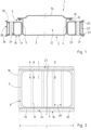
- FIGS. 1 and 2 as well as the Figures 10 and 11 show a battery carrier 1 according to the invention and components thereof.
- the battery carrier 1 has a battery tray 2 deep-drawn from a steel sheet.
- the battery tray 2 is rectangular in cross-section and has a
- the battery tray has a bottom 3 and side walls, namely two longitudinal walls 4, 5 and two end walls 6, 7, which complement each other to form a circumferential tray wall 8.
- outward-facing flange sections 10 extend along the longitudinal walls 4, 5 and the end walls 6, 7, which also complement each other in a circumferentially closed manner to form an upper flange 11.
- the tray wall 8 delimits a tray interior 12 of the battery tray 2.
- a plurality of inner struts 13 are arranged in the tub interior 12 are, optionally and as in the Figure 2 hinted at and the Figures 10 and 11 shown schematically.
- the inner struts 13 extend on the tray bottom 3 transversely between the longitudinal walls 4, 5 and are firmly fixed in the battery tray 2.
- the top of the battery tray 2 is closed by a cover 14, which rests on the edge of the flange 11.
- the cover 14 is detachably connected to the battery tray 2 by means of screw connection means 15.
- the battery carrier 1 has a reinforcement structure 16.
- the reinforcement structure 16 extends on the outside of the battery tray 2 in front of the longitudinal walls 4, 5.
- a reinforcement structure 16 has an inner profile 17 and an outer profile 18.
- the inner profile 17 is configured in a U-shaped cross section and has a rear web 19 as well as two legs 20, 21 and an external opening 22.
- the legs 20, 21 of the inner profile 17 are directed away from the battery tray 2.
- the web 19 extends parallel to the side wall or a respective longitudinal wall 4, 5.
- the opening 22 of the inner profile 17 is closed by the outer profile 18 at least in length sections.
- Both the inner profile 17 and the outer profile 18 are sheet metal parts formed from steel sheets. They can be form-hardened sheet steel components or cold-formed components made from ultra-high-strength (UHSS) cold-forming steels.
- UHSS ultra-high-strength
- the reinforcement structure 16 extends in the longitudinal direction LR of a longitudinal wall 4, 5.
- the inner profile 17 and the outer profile 18 form a hollow profile 23 at least over the majority of the length L of the reinforcement structure 16.
- sleeves 24 are provided in the hollow profile 23 of the reinforcement structure 16. These extend vertically between the legs 20, 21 of the inner profile 17. Openings 25, 26 are provided in the upper leg 20 and the lower leg 21, which are connected by the sleeves 24 (see also the Figures 7 to 9 ).
- the sleeves 24 have a sleeve body 27.
- a collar 28 is provided on the top and bottom of the sleeves 24, which is formed by a disk body 29.
- the openings 25, 26 in the upper leg 20 and in the lower leg 21, the sleeves 24 and the disk bodies 29 each lie on a common sleeve longitudinal axis LH and are arranged concentrically to this.
- Joining tabs 30, 31 are provided at the ends of the legs 20, 21.
- the joining tabs 30, 31 extend outwards from the ends 32 on longitudinal edge sections 33 of a leg 20, 21.
- the joining tabs 30, 31 are set at an angle ⁇ to the associated leg 20, 21 to which they are connected. In the Figures 7 and 9 one can see that the outer longitudinal edge sections 33 at the ends 32 of the legs 20, 21 are angled relative to the legs 20, 21.
- the joining tabs 30, 31 run along the longitudinal edge sections 33 and protrude relative to them.
- Upper joining tabs 30 are provided on the upper leg 20.
- Lower joining tabs 31 are provided on the lower leg 21.
- a plurality of joining tabs 30, 31 are arranged alternately (see Figures 7 to 9 ). There are free spaces 34 between the individual joining tabs 30, 31.
- the upper joining tabs 30 on the upper leg 20 and the lower joining tabs 31 on the lower leg 21 point away from each other.
- the outer profile 18 has joining webs 35, 36. These extend along the outer longitudinal edges 37 of the outer profile 18. With the joining webs 35, 36, the outer profile 18 rests in the area of a joining tab 30, 31. In the area of the free spaces 34, the outer profile 18 rests with the outer joining webs 35, 36 on a leg 20, 21 of an inner profile 17 on its longitudinal edges 33.
- the joining tabs 30, 31 and the joining webs 35, 36 are congruent to one another.
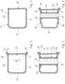
- the upper joining tabs 30 and the lower joining tabs 31 are arranged relative to each other at a tab opening angle ⁇ (see in particular Figure 3 as well as the Figures 12 to 15 ).
- the link opening angle ⁇ is between greater than or equal to ( ⁇ ) 45° and less than or equal to ( ⁇ ) 200°.
- the representation of the Figures 12 to 15 show different design variants of a reinforcement structure 16 and the tab opening angles ⁇ resulting from the alignment of the joining tabs 30, 31 and the joining webs 35, 36 relative to one another.
- the tab opening angle ⁇ 1 is approximately 95°.
- the representation of the Figure 13 shows a reinforcement structure 16 with a tab opening angle ⁇ 2 between the joining tabs 30, 31 and the joining webs 35, 36 of 40° +/- 2°.
- the tab opening angle ⁇ 3 in the embodiment of the inner profile 17 and the outer profile 18 in the reinforcement structure 16 according to the illustration of Figure 14 is about 125°.
- the tab opening angle ⁇ 4 of the reinforcement structure 16 as shown in Figure 15 is approximately 67°.
- the tab opening angle ⁇ like the Figure 3 is 90°.
- the Figure 4 shows a cross-section through the reinforcement structure 16 in an area in which the joining tabs 30, 31 merge into a free space 34.
- the sleeves 24 can also protrude with sleeve sections 39 outwardly relative to the reinforcing structure 16 and in particular above the upper leg 20.
- FIG 10 A schematic and simplified representation of an installation element 40 is shown, which is installed in the inner profile 17 or the hollow profile 23 of the reinforcement structure 16.
- Such installation elements 39 can be, for example, load-guiding bodies or bulkhead plates. These are joined to the inner profile 17, in particular joined in a materially bonded manner.
- the installation of the sleeves 24 as well as the assembly and fixing of installation elements 40 takes place from the outside with the inner profile 17 open, before this is closed by the outer profile 18 at least in lengthwise sections.
- the outer profile 18 is joined to the inner profile 17 in a material-locking manner, in particular by spot welding. This takes place in particular between the joining tabs 30, 31 and the joining webs 35, 36.
- the Figure 16 shows a section of a reinforcement profile 16.
- a joining tab 30 is bent outwards away from the leg.
- the outer profile 18 is coupled to the joining tab 30.
- the outer profile 18 has an outer joining web 35. This is slightly bent outwards relative to a central section 41 of the outer profile 18 via a changeover 42.
- the outer profile 18 or the joining web 35 has an edge strip 43 that is changed in the direction of the leg 20.
- the joining web 35 rests against the joining tab 30 and is joined to it, in particular by spot welding or spot welding bonding.
- the upper leg 20 has two leg sections 44, 45.
- the leg sections 44, 45 are aligned at an incline relative to one another.
- the leg sections 44, 45 are connected via a bend 46.
- the leg sections 44, 45 run at an angle to an orthogonal O formed by the web 19.
- the front leg section 45 in the direction of the outer profile 18 forms an angle ⁇ 1 with the orthogonal O.
- the rear leg section 44 forms an angle ⁇ 2 with the orthogonal O.
- the leg section 45 is adjoined by an outwardly turned joining tab 30 to which a joining web 35 of the outer profile 18 rests and is joined.
- the lower joining tab 31 is aligned in a straight line in extension of the lower leg 21.
- the associated joining web 36 of the outer profile 18, which is in contact with the joining tab 31 and is joined, is bent at a right angle from the web 19 of the outer profile 18 and runs parallel to the lower joining tab 31.
- the tab opening angle ⁇ 5 between the upper joining tab 30 and the lower joining tab 31 is 45 degrees.
- the upper leg 20 has three leg sections 44, 45 and 47.
- the two leg sections 44, 45 are oriented parallel to the lower leg 21.
- the leg section 47 runs perpendicular to the lower leg 21.
- the leg sections 44, 45, 47 each merge into one another via a curve or bevel 48.
- the alignment of the leg sections 44, 45, 47 relative to one another forms a step in the leg 20.
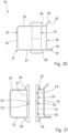
- the reinforcement structure 16 has an inner profile 17 and an outer profile 18.
- the inner profile 17 is configured in a U-shaped cross section.
- U-shaped means that the inner profile 17 has a rear web 19 and two legs 20, 21 as well as an opening 22, wherein the legs 20, 21 and the opening 22 of the inner profile 17 point away from a battery tray.
- the opening 22 of the inner profile is closed at least in length sections by the outer profile 18.
- Joining tabs 30, 31 are provided at the ends of the legs 20, 21, against which joining webs 35, 36 of the outer profile rest and are joined to the joining tabs 30, 31 in a material-to-material manner, in particular spot-welded or spot-welded.
- a sleeve 24 is arranged in the hollow profile 23 of the reinforcing structure 16. Several such sleeves 24 extend at a distance from one another in the longitudinal direction of the hollow profile 23 or the reinforcing structure 16.
- the sleeve 24 extends vertically between the legs 20, 21 of the inner profile 17.
- An upper opening 25 is provided in the upper leg 20 and a lower opening 26 is provided in the lower leg 21, which are connected by the sleeve 24.
- the sleeve 24 is in two parts and has a first sleeve body part 49 and a second sleeve body part 50.
- Each sleeve body part 49, 50 has a sleeve section 51 with which the sleeve body part 49 or 50 is guided through the opening 25 or 26.
- the sleeve body parts 49, 50 have circumferential collars 28 which rest on the outside of the upper leg 20 or lower leg 21.
- the sleeve 24 or the sleeve body parts 49, 50 are joined to the legs 20, 21 via the collars 28.
- the sleeve body parts 49, 50 are coupled to one another via a positive connection 52. This is designed like a toothing.
- the sleeve section 51 of the second sleeve body part 50 has an inner radial extension 53, which is encompassed by an outer radial collar 54 of the sleeve section 51 on the first sleeve body part 49.
Landscapes
- Engineering & Computer Science (AREA)
- Chemical & Material Sciences (AREA)
- Chemical Kinetics & Catalysis (AREA)
- Electrochemistry (AREA)
- General Chemical & Material Sciences (AREA)
- Transportation (AREA)
- Mechanical Engineering (AREA)
- Life Sciences & Earth Sciences (AREA)
- Sustainable Energy (AREA)
- Power Engineering (AREA)
- Sustainable Development (AREA)
- Aviation & Aerospace Engineering (AREA)
- Combustion & Propulsion (AREA)
- Battery Mounting, Suspending (AREA)
- Body Structure For Vehicles (AREA)
Abstract
Description
- Die Erfindung betrifft einen Batterieträger gemäß den Merkmalen im Oberbegriff von Anspruch 1.
- Zur Halterung von Batterieelementen für die Bereitstellung elektrischer Energie in elektrisch angetriebenen Fahrzeugen werden Batterieträger verwendet, die zwischen den Achsen des Fahrzeugs angeordnet sind. Zu den wesentlichen sicherheitstechnischen Anforderungen an einen Batterieträger gehört eine gute Crashperformance. Um diesen zu genügen ist die Batteriewanne durch eine äußere Verstärkungsstruktur geschützt.
- Durch die
DE 10 2018 126 068 A1 zählt ein Batterieträger für ein Elektrofahrzeug zum Stand der Technik. Der Batterieträger weist eine Batteriewanne auf, die in einen äußeren Rahmen eingesetzt ist und durch einen Deckel verschlossen ist. Der Rahmen ist im Querschnitt aus mindestens zwei miteinander gefügten Profilbauteilen hergestellt, wobei mindestens eines dieser Profilbauteile als Blechumformbauteil hergestellt ist. - Auch bei dem aus der
DE 10 2016 120 826 B4 bekannten Batterieträger ist die Batteriewanne durch eine diese außenseitig umgebende, eine Hohlkammer aufweisende Rahmenstruktur geschützt. - Die
DE 10 2018 120 371 B4 offenbart einen Batterieträger mit einer äußeren Verstärkung durch eine Rahmenstruktur, die aus mehreren, im Bereich ihrer Enden miteinander verbundenen Hohlkammerprofilteilen zusammengesetzt ist. - Weiterhin beschreibt die
WO 2018/166895 A1 einen Batterieträger zur Aufnahme von Batterieelementen mit einem einen Innenbereich bildenden Rahmen, welcher zumindest teilweise Seitenwände des Batterieträgers bereitstellt und einer Verstärkungsstruktur, die ein oder mehrere Verstärkungsprofile umfasst. - Die Batterieträger müssen mechanisch stabil sein und an der Karosserie bzw. am Fahrgestell eines Fahrzeugs befestigt werden. Die Batteriewanne soll weitestgehend in die Karosserie integriert werden, wodurch sich konstruktive und montagetechnische Herausforderungen stellen.
- Der Erfindung liegt ausgehend vom Stand der Technik die Aufgabe zugrunde, einen in seiner Funktionalität und Crashperformance verbesserten Batterieträger zu schaffen.
- Die Lösung dieser Aufgabe besteht nach der Erfindung in einem Batterieträger gemäß Anspruch 1.
- Ein Batterieträger zur Halterung von Batterieelementen für die Bereitstellung elektrischer Energie in elektrisch angetriebenen Fahrzeugen weist eine Batteriewanne mit einer Verstärkungsstruktur auf, die außenseitig vor zumindest einer Seitenwand der Batteriewanne angeordnet ist.
- Die Verstärkungsstruktur umfasst ein Innenprofil und ein Außenprofil. Das Innenprofil ist im Querschnitt U-förmig konfiguriert und weist einen Steg und zwei Schenkel sowie eine Öffnung auf. Der Steg ist parallel zur Seitenwand orientiert. Die Schenkel des Innenprofils weisen von der Batteriewanne weg, so dass die offene Seite des Innenprofils außen liegt. Die offene Seite bzw. die Öffnung des Innenprofils ist zumindest längenabschnittsweise durch das Außenprofil geschlossen.
- Diese Ausgestaltung führt zu einem funktional und hinsichtlich der Crashperformance, insbesondere im Steifigkeitsverhalten, verbesserten Batterieträger. Das Innenprofil ist über die Öffnung und die nach außen von der Batteriewanne weg gerichtete offene Seite des Innenprofils gut zugänglich. Hierdurch wird die Funktionalität, insbesondere die Zugänglichkeit und die Montage des Innenprofils selbst ebenso wie vom in Innenprofil zu montierenden Bauteilen verbessert. Das Innenprofil und das Außenprofil ergänzen sich synergistisch. Die Verstärkungsstruktur erstreckt sich in Längsrichtung der Seitenwand. Das Innenprofil und das Außenprofil bilden zumindest auf dem überwiegenden Teil der Länge der Verstärkungsstruktur ein kastenförmiges Hohlprofil. Dieses zeichnet sich durch ein vorteilhaftes statisches und dynamisches Belastungsverhalten auf. Insbesondere ist die Steifigkeit der Verstärkungsstruktur quer zur Batteriewanne verbessert. Dabei können die Schenkel des Innenprofils bei einem Seitenaufprall unter Energieabbau deformieren, wobei das Außenprofil als Zugstrebe fungiert und die Schenkel noch zueinander in Position hält.
- Längenabschnittsweise geschlossen bedeutet, dass die Öffnung des Innenprofils auf der gesamten Länge des Innenprofils durch ein Außenprofil geschlossen sein kann. Das Außenprofil kann die Öffnung auch nur auf einem Längenabschnitt des Innenprofils verschließen. Auch können mehrere Außenprofile vorgesehen sein, welche die Öffnung des Innenprofils zumindest auf dem überwiegenden Teil der Länge verschließen. Auch kann ein Außenprofil insbesondere zur Gewichtseinsparung gelocht ausgebildet sein bzw. mit Löchern und Aussparungen versehen sein. Insbesondere kann das Außenprofil ovale oder rechteckförmige Löcher bzw. Ausnehmungen aufweisen. Rechteckförmige Löcher bzw. Ausnehmungen besitzen insbesondere gerundete Eckbereiche. Solche als Langlöcher ausgebildete ovale oder rechteckförmige Löcher bzw. Ausnehmungen besitzen vorzugsweise eine Abmessung zwischen 20 x 80 mm und 60 x 80 mm.
- Löcher bzw. Ausnehmungen im Außenprofil können auch zum Fügen der Verstärkungsstruktur mit der Seitenwand der Batteriewanne dienen.
- In der Verstärkungsstruktur ist zumindest eine Hülse vorgesehen. Hierbei handelt es sich um Befestigungs- bzw. Montagehülsen. Üblicherweise sind in Längsrichtung der Verstärkungsstruktur mehrere mit einem Abstand zueinander angeordneten Hülsen vorgesehen. Eine Hülse erstreckt sich zwischen den Schenkeln des Innenprofils über die gesamte Höhe des Innenprofils. Die Hülse verbindet Öffnungen in den Schenkeln. Die Hülsen sind koaxial zu den Öffnungen orientiert. Hülse und Öffnung liegen auf einer gemeinsamen Längsachse. Die Hülsen dienen zur Durchführung von Befestigungsmittelen, über welche der Batterieträger in der Karosserie bzw. dem Chassis eines Fahrzeugs festgelegt wird. Insbesondere erfolgt über die Hülsen und geeignete Befestigungsmittel eine Festlegung des Batterieträgers an Seitenschwellern und gegebenenfalls Bodenquerträgern im Kraftfahrzeug.
- Eine vorteilhafte Ausgestaltung sieht vor, dass die Hülsen einen oberen und/oder einen unteren Kragen aufweisen. Ein Kragen ist vom Hülsenkörper nach auswärts orientiert. Der Kragen kann werkstoffeinheitlicher Bestandteil der Hülse sein oder durch einen separaten Kragenkörper gebildet sein. Die Kragen nehmen die Reib- und Druckkräfte auf, die beim Anziehen von durch die Hülsen geführten Montageelementen, beispielsweise Schraubverbindungselementen, entstehen. Hierdurch kann die Oberfläche der Bauteile im Bereich einer Schraubverbindung vor Beschädigungen geschützt und die Flächenpressung reduziert werden. Insbesondere gewährleisten die Kragen einen Toleranzausgleich. Die ebene Kragenfläche ist größer als die Hülsenfläche, so dass eine horizontale Ausrichtung bzw. Positionierung der Hülsen bzw. deren Hülsenkörper vor dem Schweißen mit dem Innenprofil erfolgen kann. Die Ausrichtung erfolgt entsprechend der definierten seitlichen Schwellerlochabstände.
- Eine Hülse bzw. der Hülsenkörper einer Hülse kann mehrteilig ausgeführt sein. Insbesondere kann eine Hülse zweiteilig, also aus zwei Hülsenkörperteilen, zusammengesetzt sein. Insbesondere erfolgt das Zusammenfügen der beiden Hülsenkörperteile bei der Montage in der Verstärkungsstruktur.
- Die Hülsen können mit ihren Kragen innen an der Innenseite eines Schenkels des Innenprofils anliegen. Eine für die Praxis besonders vorteilhafte Ausgestaltung sieht vor, dass die Hülsen außenseitig an den Schenkeln anliegen. In diesem Zusammenhang sind insbesondere zweiteilige Hülsen vorteilhaft. Eine zweiteilige Hülse weist zwei Hülsenkörperteile auf. Ein Hülsenkörperteil wird jeweils von außen durch eine Öffnung in einem Schenkel hindurchgeführt, so dass die Kragen außen an den Innenschenkeln anliegen. Eine Fügung der Hülsen mit dem Innenprofil erfolgt dann im Bereich der Kragen. Des Weiteren werden die beiden Hülsenkörperteile im Inneren des Innenprofils zusammengeführt und miteinander gefügt. Dies kann kraft- und/oder formschlüssig erfolgen. Die Fügung zwischen den beiden Hülsenkörperteilen kann durch eine Verzahnung oder auch durch einen Presssitz erfolgen. Auch eine bajonettartige Verbindung ist möglich.
- Eine zweiteilige Hülse ist vorteilhaft hinsichtlich der Montage. Jeweils ein Hülsenkörperteil wird durch eine obere bzw. untere Schenkelöffnung geführt und teilüberlappend insbesondere mittels Presssitz verbunden. Im Innenprofil positioniert werden die Hülsen über die Kragen mit dem Innenprofil bzw. den Schenkeln des Innenprofils verschweißt.
- Eine Hülse kann auch durch eine Innenhülse und eine Außenhülse gebildet sein.
- Endseitig der Schenkel des Innenprofils sind Fügelaschen vorgesehen. Vorzugsweise sind mehrere mit Abstand zueinander angeordnete Fügelaschen in Längsrichtung des Innenprofils entlang von Längskantenabschnitten der Schenkel vorgesehen. Die Fügelaschen stehen nach außen gerichtet vor. Vorzugsweise ist an jedem Schenkel entlang seines Längskantenabschnitts eine alternierende Reihe von Fügelaschen vorgesehen. Die Fügelaschen liegen in Längsrichtung eines Schenkels mit Abstand zueinander, so dass jeweils zwischen den Fügelaschen Freiräume vorhanden sind.
- Das Außenprofil stützt sich an den freien Enden bzw. den Längskantenabschnitten der Schenkel und/oder an den Fügelaschen der Schenkel ab.
- Vorzugsweise ist eine Fügelasche in einem Winkel zu einem Schenkel angestellt. Insbesondere sind die Fügelaschen vom freien Ende der Schenkel weg nach außen gerichtet. Hierdurch wird die Zugänglichkeit verbessert, insbesondere für die Herstellung von Punktschweißverbindungen. Auch wird der benötigte Bauraum nach außen hin verringert.
- Das Außenprofil weist Fügestege auf, welche sich an den Schenkeln des Innenprofils abstützen. Insbesondere liegt das Außenprofil mit Fügestegen bereichsweise an den Fügelaschen an.
- Das Außenprofil ist mit dem Innenprofil stoffschlüssig verbunden. Dies erfolgt über eine stoffschlüssige Fügung zwischen den Fügelaschen des Innenprofils und den Fügestegen des Außenprofils. Insbesondere erfolgt die stoffschlüssige Fügung zwischen Fügelaschen und Fügesteg durch eine Punktschweißverbindung oder ein Punktschweißkleben. Diese Fügetechniken gewährleisten einen geringen Wärmeeintrag in die Bauteile beim stoffschlüssigen Fügen. Grundsätzlich ist auch ein Rollnahtschweißen oder ein Laserschweißen möglich.
- Eine weitere vorteilhafte Ausgestaltung sieht vor, dass obere und untere Fügelaschen vorgesehen sind. Eine obere Lasche befindet sich endseitig am oberen Schenkeln des Innenprofils. Eine untere Fügelasche befindet sich endseitig am freien Ende des unteren Schenkels des Innenprofils. Die obere Fügelasche und die untere Fügelasche sind jeweils vom zugehörigen oberen Schenkel bzw. unteren Schenkel nach außen in einem Winkel orientiert. Hierbei sind die obere Fügelasche und die untere Fügelasche voneinander wegweisend gerichtet.
- Die obere Fügelaschen und die unteren Fügelaschen sind zueinander in einem Laschenöffnungswinkel angeordnet. Der Laschenöffnungswinkel kann zwischen größer gleich (≥) 45° und kleiner gleich (≤) 240° bemessen. Vorzugsweise liegt der Laschenöffnungswinkel in einer Spanne zwischen jeweils einschließlich 80° und 150° Insbesondere ist der Laschenöffnungswinkel zwischen jeweils einschließlich 60° und 120° bemessen.
- Die Fügelaschen am Innenprofil und die Fügestege des Außenprofils sind konturmäßig aneinander angepasst und ergänzen sich komplementär. Besonders vorteilhaft sind die Fügelaschen und die Fügestege gleichwinklig angestellt und zueinander komplementär ausgerichtet.
- Eine für die Praxis besonders vorteilhafte Ausführungsform sieht vor, dass in der Verstärkungsstruktur Einbauelemente vorgesehen sind. Einbauelemente könnten Lastleitkörper, Schottbleche und ähnliche innenliegende Verstärkungs- und/oder Funktionsbauteile sein.
- Die Verstärkungsstruktur ist mit der Batteriewanne verbunden. Hierzu ist das Innenprofil mit der Batteriewanne gefügt. Insbesondere ist das Innenprofil mit seinem rückseitigen Steg an einer Seitenwand der Batteriewanne anliegend gefügt. Das offene Innenprofil ist von der Seite aus vorteilhaft zugänglich. In das offene Innenprofil können die Hülsen ebenso wie weitere Einbauelemente eingebracht und montiert werden. Anschließend wird das Innenprofil durch ein oder mehrere Außenprofile verschlossen. Das oder jedes Außenprofil ist mit dem oberen Schenkel und dem unteren Schenkel verbunden und fungiert als Zuglaststrebe zwischen den Schenkeln, die einem Aufspreizen des Innenprofils bei einem Seitenanprall entgegen wirkt.
- Zwischen den Fügelaschen an den Schenkeln des Innenprofils sind Ausschnitte oder Aussparungen vorgesehen. Auch kann die Kontur der Schenkel auf die Anbindung an Fügeflächen abgestimmt sein. Eine Ausgestaltung sieht in diesem Zusammenhang vor, dass das Innenprofil bereichsweise im Bereich eines Einbauelements und/oder im Bereich einer Hülse verprägt bzw. eingezogen ist.
- Neben Einbauelementen in der Verstärkungsstruktur können auch in der Batteriewanne Verstärkungs- bzw. Versteifungselemente integriert sein. Solche Verstärkungs- bzw. Versteifungselemente können durch Längs- und oder Querprofile bzw. -streben gebildet sein, die sich am Wannenboden erstrecken.
- Weiterhin kann ein Deckel den oberen Abschluss der Batteriewanne bilden. Besonders vorteilhaft ist der Batterieträger dafür ausgelegt und bestimmt, in die Karosserie bzw. dem Chassis eines Fahrzeugs integriert zu werden. Der Batterieträger bildet dabei ein tragendes Teil der Karosserie (Cell-to-Body). Hierbei kann der Fußboden des Fahrzeugs den Batteriedeckel bilden.
- Die Batteriewanne ist insbesondere ein einstückig und werkstoffeinheitlich ausgeführtes Tiefziehteil. Auch das Innenprofil und das Außenprofil können pressformtechnisch bzw. tiefzieh-technisch hergestellt sein. Durch seinen U-förmigen Querschnitt besitzt das Innenprofil einen kanalartigen Verlauf, in welchem in Längsrichtung mit Abstand zueinander mehrere Hülsen angeordnet sind. Das zumindest eine Außenprofil verschießt das Innenprofil schließblechartig auf zumindest einem Teil seiner Länge. In Längsrichtung der Verstärkungsstruktur können mehrere Außenprofile vorgesehen sein. Das eine Außenprofil oder die mehreren Außenprofile bilden die Außenwand der Verstärkungsstruktur.
- Die Batteriewanne kann auch aus einer Blechplatine falttechnisch zur Batteriewanne geformt sein. Hierzu wird eine Blechplatine bereitgestellt, deren Geometrie der Abwicklung der Batteriewanne entspricht. Eine Kühlplatte kann optional direkt mit der Blechplatine gefügt werden, bevor diese dann falttechnisch zur Batteriewanne geformt wird. Die Batteriewanne ist als Faltbauteil ausgeführt. Faltecken der Batteriewanne sind gefügt und abgedichtet.
- Die Batteriewanne ebenso wie die Verstärkungsstruktur und die die Verstärkungsstruktur bildenden Bauteile, insbesondere die Innenschale, aber auch die Außenschale, können durch Formhärten von Stahlblechen gebildet sein. Das Formhärten wird auch als Presshärten bezeichnet. Beim Formhärten wird ein Blech aus einem Mangan-Bor-Stahl auf eine Temperatur oberhalb der spezifischen Austenitisierungstemperatur des Werkstoffs erwärmt, in ein Umformwerkzeug eingelegt und zum Formbauteil warm umgeformt, wobei es während der Formgebung abkühlt. Im Umformwerkzeug eingespannt werden die Formbauteile durch die Kühlung gehärtet.
- Hierbei können auch beschichtete formhärtbare Stahlbleche zum Einsatz gelangen, insbesondere handelt es sich hierbei um mit einer Aluminium/Silizium-Beschichtung versehene Mangan-Bor-Stahlbleche. Die Bauteile der Verstärkungsstruktur und der Batteriewanne weisen Zugfestigkeiten von 1.000 MPa und höher auf.
- Die Batteriewanne ebenso wie das Innenprofil und/oder das Außenprofil der Verstärkungsstruktur können auch aus extra- und ultrahochfesten Kaltformstählen gefertigt sein. Die Bauteile weisen eine Zugfestigkeit von mehr als 980 MPa auf, insbesondere weist das Innenprofil eine Zugfestigkeit von ≥ 1.180 MPa auf.
- Grundsätzlich ist in beiden Fällen für die Batteriewanne sowie für das Innenprofil und/oder das Außenprofil auch der Einsatz von tailored blanks verschiedener Blechdicke, Stahlgüte oder auch von Technologien zur Erstellung maßgeschneideter Festigkeitseigenschaften mit lokalen weichen Bereichen (soft zones) möglich, beispielsweise zur Risspräventation beim Schweißen oder zur gezielten Einstellung lokal geschwächter Zonen mit besserem Deformationsvermögen zur Energieabsorption.
- Die Erfindung ist nachfolgend anhand von in den Zeichnungen dargestellten Ausführungsbeispielen näher beschrieben. Es zeigen:
- Figur 1
- einen erfindungsgemäßen Batterieträger in einer Querschnittsdarstellung;
- Figur 2
- den Batterieträger in einer schematisierten Draufsicht,
- Figur 3
- einen Querschnitt durch die Verstärkungsstruktur des Batterieträgers gemäß der Darstellung von
Figur 2 entlang der Linie A-A; - Figur 4
- einen Querschnitt durch die Verstärkungsstruktur des Batterieträgers gemäß der Darstellung von
Figur 2 entlang der Linie B-B; - Figur 5
- einen Querschnitt durch die Verstärkungsstruktur des Batterieträgers gemäß der Darstellung von
Figur 2 entlang der Linie C-C; - Figur 6
- einen Querschnitt durch die Verstärkungsstruktur des Batterieträgers gemäß der Darstellung von
Figur 2 entlang der Linie D-D; - Figur 7
- einen Ausschnitt aus der Verstärkungsstruktur des Batterieträgers im Bereich einer Montagehülse in einer Perspektive;
- Figur 8
- eine Seitenansicht auf die Darstellung entsprechend
Figur 7 ; - Figur 9
- die Darstellung entsprechend der
Figur 7 in einer perspektivischen Ansicht schräg von vorne; - Figur 10
- eine weitere Ausführungsform eines erfindungsgemäßen Batterieträgers in einer Querschnittsdarstellung;
- Figur 11
- den Batterieträger gemäß der Darstellung von
Figur 10 in einer schematisierten Draufsicht; - Figuren 12 bis 15
- jeweils einen technisch schematisiert dargestellten Querschnitt durch weitere Ausführungsformen einer Verstärkungsstruktur;
- Figur 16
- einen Ausschnitt aus einem Verstärkungsprofil mit der Darstellung des Fügebereichs zwischen dem Innenprofil und dem Außenprofil;
- Figuren 17 bis 19
- jeweils einen technisch schematisiert dargestellten Querschnitt durch eine Ausführungsform einer Verstärkungsstruktur;
- Figur 20
- eine Ansicht auf eine weitere Ausführungsform einer Verstärkungsstruktur und
- Figur 21
- die Darstellung gemäß der
Figur 20 in einem Querschnitt. - In den
Figuren 1 bis 21 werden für gleiche oder funktionell einander entsprechende Bauteile bzw. Bauteilkomponenten die gleichen Bezugszeichen verwendet, auch wenn aus Gründen der Vereinfachung auf eine wiederholte Beschreibung verzichtet wird. - Die
Figuren 1 und 2 ebenso wie dieFiguren 10 und 11 zeigen einen erfindungsgemäßen Batterieträger 1 sowie Bauteile davon. - Der Batterieträger 1 weist eine aus einem Stahlblech tiefgezogene Batteriewanne 2 auf. Die Batteriewanne 2 ist im Querschnitt rechteckig konfiguriert und weist einen Wannenboden 3 sowie Seitenwände, nämlich jeweils zwei Längswände 4, 5 und zwei Stirnwände 6, 7 auf, die sich zu einer umlaufenden Wannenwand 8 ergänzen. Am oberen Wannenrand 9 erstrecken sich entlang der Längswände 4, 5 und der Stirnwände 6, 7 nach außen gerichtete Flanschabschnitte 10, die sich ebenfalls umlaufend geschlossen zu einem oberen Flansch 11 ergänzen. Die Wannenwand 8 begrenzt einen Wanneninnenraum 12 der Batteriewanne 2.
- Im Wanneninnenraum 12 sind, optional und wie in der
Figur 2 andeutungsweise und denFiguren 10 und 11 schematisiert dargestellt, eine Mehrzahl von Innenstreben 13 angeordnet. Die Innenstreben 13 erstrecken sich auf dem Wannenboden 3 quer zwischen den Längswänden 4, 5 und sind stoffschlüssig in der Batteriewanne 2 festgelegt. - Oberseitig ist die Batteriewanne 2 durch einen Deckel 14 verschlossen, der randseitig auf dem Flansch 11 aufliegt. In den dargestellten Ausführungsbeispielen ist der Deckel 14 lösbar mittels Schraubverbindungsmitteln 15 mit der Batteriewanne 2 verbunden.
- Der Batterieträger 1 weist eine Verstärkungsstruktur 16 auf. Die Verstärkungsstruktur 16 erstreckt sich jeweils außenseitig der Batteriewanne 2 vor den Längswänden 4, 5.
- Wie insbesondere die
Figuren 1 sowie dieFiguren 3 bis 6 und die dieFigur 10 zeigen, weist eine Verstärkungsstruktur 16 ein Innenprofil 17 und ein Außenprofil 18 auf. Das Innenprofil 17 ist im Querschnitt U-förmig konfiguriert und weist einen rückwärtigen Steg 19 sowie zwei Schenkel 20, 21 und eine außenseitige Öffnung 22 auf. Die Schenkel 20, 21 des Innenprofils 17 sind von der Batteriewanne 2 weg gerichtet. Der Steg 19 erstreckt sich parallel zur Seitenwand bzw. jeweils einer Längswand 4, 5. Die Öffnung 22 des Innenprofils 17 ist durch das Außenprofil 18 zumindest längenabschnittsweise geschlossen. - Sowohl das Innenprofil 17 als auch das Außenprofil 18 sind Blechformteile, die aus Stahlblechen geformt sind. Es kann sich um formgehärtete Stahlblechbauteile oder um kaltgeformte Formbauteile aus insbesondere ultrahochfesten (UHSS) Kaltformstählen handeln.
- Die Verstärkungsstruktur 16 erstreckt sich in Längsrichtung LR einer Längswand 4, 5. Das Innenprofil 17 und das Außenprofil 18 bilden zumindest auf dem überwiegenden Teil der Länge L der Verstärkungsstruktur 16 ein Hohlprofil 23.
- Im Hohlprofil 23 der Verstärkungsstruktur 16 sind mehrere Hülsen 24 vorgesehen. Diese erstrecken sich vertikal zwischen den Schenkeln 20, 21 des Innenprofils 17. In dem oberen Schenkel 20 und dem unteren Schenkel 21 sind jeweils Öffnungen 25, 26 vorgesehen, welche durch die Hülsen 24 verbunden werden (siehe hierzu auch die
Figuren 7 bis 9 ). Die Hülsen 24 weisen einen Hülsenkörper 27 auf. Ober- und unterseitig der Hülsen 24 ist jeweils ein Kragen 28 vorgesehen, der durch einen Scheibenkörper 29 gebildet ist. Die Öffnungen 25, 26 im oberen Schenkel 20 und im unteren Schenkel 21, die Hülsen 24 und die Scheibenkörper 29 liegen jeweils auf einer gemeinsamen Hülsenlängsache LH und sind konzentrisch zu dieser angeordnet. - Endseitig der Schenkel 20, 21 sind Fügelaschen 30, 31 vorgesehen. Die Fügelaschen 30, 31 erstrecken sich von den Enden 32 an Längskantenabschnitten 33 eines Schenkels 20, 21 nach außen. Die Fügelaschen 30, 31 sind in einem Winkel α zu dem zugehörigen Schenkel 20, 21 angestellt, an welchen sie sich anschließen. In den
Figuren 7 und 9 erkennt man, dass die äußeren Längskantenabschnitte 33 an den Enden 32 der Schenkel 20, 21 gegenüber den Schenkeln 20, 21 abgewinkelt sind. Die Fügelaschen 30, 31 verlaufen entlang der Längskantenabschnitte 33 und stehen gegenüber diesen vor. - Am oberen Schenkel 20 sind obere Fügelaschen 30 vorgesehen. Am unteren Schenkel 21 sind untere Fügelaschen 31 vorgesehen. In Längsrichtung LR der Schenkel 20, 21 entlang der Länge des Innenprofils 17 ist eine Mehrzahl von Fügelaschen 30, 31 alternierend angeordnet (siehe hierzu
Figuren 7 bis 9 ). Zwischen den einzelnen Fügelaschen 30, 31 befinden sich Freiräume 34. Die oberen Fügelaschen 30 am oberen Schenkel 20 und die unteren Fügelaschen 31 am unteren Schenkel 21 sind voneinander weg weisend gerichtet. - Das Außenprofil 18 weist Fügestege 35, 36 auf. Diese erstrecken sich jeweils entlang der äußeren Längsränder 37 des Außenprofils 18. Mit den Fügestegen 35, 36 liegt das Außenprofil 18 im Bereich einer Fügelasche 30, 31 an. Im Bereich der Freiräume 34 liegt das Außenprofil 18 mit den äußeren Fügestegen 35, 36 jeweils an einem Schenkel 20, 21 eines Innenprofils 17 an dessen Längskanten 33 an. Die Fügelaschen 30, 31 und die Fügestege 35, 36 sind kongruent zueinander ausgebildet.
- Die oberen Fügelaschen 30 und die unteren Fügelaschen 31 sind zueinander in einem Laschenöffnungswinkel β angeordnet (siehe hierzu insbesondere
Figur 3 sowie dieFiguren 12 bis 15 ). Der Laschenöffnungswinkel β ist zwischen größer oder gleich (≥) 45° und kleiner oder gleich (≤) 200° bemessen. Die Darstellung derFiguren 12 bis 15 zeigen verschiedene Ausführungsvarianten einer Verstärkungsstruktur 16 und die sich durch die Ausrichtung der Fügelaschen 30, 31 und der Fügestege 35, 36 relativ zueinander ergebenden Laschenöffnungswinkel β. - Bei der Darstellung der
Figur 12 beträgt der Laschenöffnungswinkel β1 ca. 95°. - Die Darstellung der
Figur 13 zeigt eine Verstärkungsstruktur 16 mit einem Laschenöffnungswinkel β2 zwischen den Fügelaschen 30, 31 und den Fügestegen 35, 36 von 40° +/- 2°. - Der Laschenöffnungswinkel β3 bei der Ausführungsform des Innenprofils 17 und des Außenprofils 18 bei der Verstärkungsstruktur 16 gemäß der Darstellung von
Figur 14 beträgt etwa 125°. - Der Laschenöffnungswinkel β4 der Verstärkungsstruktur 16 gemäß der Darstellung von
Figur 15 beträgt ca. 67°. - In den
Figuren 3 bis 5 sind Querschnitte durch die Verstärkungsstruktur 16 des Batterieträgers 1 entlang der Linien A-A, B-B, C-C und D-D dargestellt. - Der Laschenöffnungswinkel β, wie der
Figur 3 zu entnehmen, beträgt 90°. DieFigur 4 zeigt einen Querschnitt durch die Verstärkungsstruktur 16 in einem Bereich, in welchem die Fügelaschen 30, 31 in einen Freiraum 34 übergehen. - Die
Figuren 5 und 6 verdeutlichen, dass Hülsen 24 eingesetzt sind, welche im Durchmesser verschieden groß bemessen sind. - Anhand der
Figur 6 ist ferner zu erkennen, dass der Verlauf der Schenkel 20, 21 quer zur Längsrichtung des Innenprofils 17 eine von einem gradlinigen Verlauf abweichende Kontur haben kann. Ein hinterer Teil ist durch eine Umstellung 38 verkröpft. - Wie insbesondere in der
Figur 9 zu erkennen, können die Hülsen 24 auch mit Hülsenabschnitten 39 außen gegenüber der Verstärkungsstruktur 16 und insbesondere oberhalb des oberen Schenkels 20 vorstehen. - In der
Figur 10 ist schematisiert und vereinfacht dargestellt ein Einbauelement 40, welches in das Innenprofil 17 bzw. das Hohlprofil 23 der Verstärkungsstruktur 16 eingebaut ist. Solche Einbauelemente 39 können beispielsweise Lastleitkörper oder Schottbleche sein. Diese sind mit dem Innenprofil 17 gefügt, insbesondere stoffschlüssig gefügt. - Der Einbau der Hülsen 24 ebenso wie die Montage und Festlegung von Einbauelementen 40 erfolgt von außen bei offenem Innenprofil 17, bevor dieses durch das Außenprofil 18 zumindest längenabschnittsweise geschlossen wird. Hierzu wird das Außenprofil 18 ist mit dem Innenprofil 17 stoffschlüssig gefügt, insbesondere durch Punktschweißen. Dies erfolgt insbesondere zwischen den Fügelaschen 30, 31 und den Fügestegen 35, 36.
- Die
Figur 16 zeigt einen Ausschnitt aus einem Verstärkungsprofil 16. Endseitig des Schenkels 20 ist eine Fügelasche 30 vom Schenkel weg nach außen gerichtet abgekantet. Das Außenprofil 18 ist an der Fügelasche 30 gekoppelt. Das Außenprofil 18 weist einen äußeren Fügesteg 35 auf. Dieser ist gegenüber einem Mittelabschnitt 41 des Außenprofils 18 über eine Umstellung 42 leicht nach außen verkröpft. Am Außenrand weist das Außenprofil 18 bzw. der Fügesteg 35 eine in Richtung zum Schenkel 20 umgestellte Randleiste 43 auf. Der Fügesteg 35 liegt an der Fügelasche 30 an und ist mit dieser gefügt, insbesondere durch Punktschweißen oder Punktschweißkleben. - Bei dem in der
Figur 17 dargestellten Querschnitt durch eine Verstärkungsstruktur 16 weist der obere Schenkel 20 zwei Schenkelabschnitte 44, 45 auf. Die Schenkelabschnitte 44, 45 sind relativ zueinander geneigt ausgerichtet. - Die Schenkelabschnitte 44, 45 sind über eine Biegung 46 verbunden. Zu einer mit dem Steg 19 gebildeten Orthogonale O verlaufen die Schenkelabschnitte 44, 45 geneigt. Der in Richtung zum Außenprofil 18 vordere Schenkelabschnitt 45 nimmt mit der Orthogonalen O einen Winkel δ1 ein. Der hintere Schenkelabschnitt 44 nimmt mit der Orthogonalen O einen Winkel δ2 ein. Öffnungsseitig schließt sich an den Schenkelabschnitt 45 eine auswärts umgestellte Fügelasche 30 an, an welche ein Fügesteg 35 des Außenprofils 18 anliegt und gefügt ist.
- Der in der
Figur 18 dargestellte Querschnitt einer Verstärkungsstruktur 16 entspricht im Wesentlichen derjenigen vonFigur 17 . Allerdings verläuft der vordere Schenkelabschnitt 45 parallel zum unteren Schenkel 21. Der Schenkelabschnitt 45 ist folglich geradlinig konform zum unteren Schenkel 21 ausgerichtet. Der hintere Schenkelabschnitt 44 verläuft geneigt zwischen dem Steg 19 und dem vorderen Schenkelabschnitt 45. Im dargestellten Ausführungsbeispiel beträgt der Neigungswinkel δ2 etwa 30 Grad. - Sowohl bei der Ausführungsform der Verstärkungsstruktur 16 gemäß der Darstellung von
Figur 17 als auch derFigur 18 ist die untere Fügelasche 31 geradlinig in Verlängerung des unteren Schenkels 21 ausgerichtet. Der zugehörige Fügesteg 36 des Außenprofils 18, welcher mit der Fügelasche 31 in Kontakt steht und gefügt ist, ist entsprechend rechtwinklig vom Steg 19 des Außenprofils 18 abgekantet und verläuft parallel zur unteren Fügelasche 31. Der Laschenöffnungswinkel β5 zwischen der oberen Fügelasche 30 und der unteren Fügelasche 31 beträgt 45 Grad. - Bei dem in der
Figur 19 dargestellten Querschnitt einer Verstärkungsstruktur 16 weist der obere Schenkel 20 drei Schenkelabschnitte 44, 45 und 47 auf. Die beiden Schenkelabschnitte 44, 45 sind parallel zum unteren Schenkel 21 orientiert. Der Schenkelabschnitt 47 verläuft senkrecht zum unteren Schenkel 21. Die Schenkelabschnitte 44, 45, 47 gehen jeweils über eine Krümmung bzw. Abkantung 48 ineinander über. Durch die Ausrichtung der Schenkelabschnitte 44, 45, 47 relativ zueinander wird im Schenkel 20 eine Stufe gebildet. - Die Ausführungsform der Verstärkungsstruktur 16, wie in den
Figuren 20 und 21 dargestellt, entsprechen im grundsätzlichen Aufbau den zuvor beschriebenen. - Die Verstärkungsstruktur 16 weist ein Innenprofil 17 und ein Außenprofil 18 auf. Das Innenprofil 17 ist im Querschnitt U-förmig konfiguriert. U-förmig bedeutet, dass das Innenprofil 17 einen rückwärtigen Steg 19 und zwei Schenkel 20, 21 sowie eine Öffnung 22 aufweist, wobei die Schenkel 20, 21 und die Öffnung 22 des Innenprofils 17 von einer Batteriewanne weg weisen. Die Öffnung 22 des Innenprofils ist zumindest längenabschnittsweise durch das Außenprofil 18 geschlossen. Endseitig der Schenkel 20, 21 sind Fügelaschen 30, 31 vorgesehen, an welche Fügestege 35, 36 des Außenprofils anliegen und mit den Fügelaschen 30, 31 stoffschlüssig gefügt sind, insbesondere punktgeschweißt bzw. punktschweißgeklebt.
- Im Hohlprofil 23 der Verstärkungsstruktur 16 ist eine Hülse 24 angeordnet. In Längsrichtung des Hohlprofils 23 bzw. der Verstärkungsstruktur 16 erstrecken sich mehrere solcher Hülsen 24 mit Abstand zueinander.
- Die Hülse 24 erstreckt sich vertikal zwischen den Schenkeln 20, 21 des Innenprofils 17. Im oberen Schenkel 20 ist eine obere Öffnung 25 und im unteren Schenkel 21 ist eine untere Öffnung 26 eingebracht, welche durch die Hülse 24 verbunden sind.
- Die Hülse 24 ist zweiteilig und weist einen ersten Hülsenkörperteil 49 und einen zweiten Hülsenkörperteil 50 auf. Jeder Hülsenkörperteil 49, 50 weist einen Hülsenabschnitt 51 auf, mit welchem der Hülsenkörperteil 49 bzw. 50 durch die Öffnung 25 bzw. 26 geführt ist. Endseitig besitzen die Hülsenkörperteile 49, 50 umlaufende Kragen 28, welche außenseitig am oberen Schenkel 20 bzw. unteren Schenkel 21 anliegen. Über die Kragen 28 ist die Hülse 24 bzw. die Hülsenkörperteile 49, 50 mit den Schenkeln 20, 21 gefügt.
- Die Hülsenkörperteile 49, 50 sind untereinander über eine Formschlussverbindung 52 gekoppelt. Diese ist verzahnungsartig gestaltet. Hierzu weist der Hülsenabschnitt 51 des zweiten Hülsenkörperteils 50 einen inneren radialen Fortsatz 53 auf, der von einem äußeren Radialbund 54 des Hülsenabschnitts 51 am ersten Hülsenkörperteil 49 umgriffen ist.
-
- 1 -
- Batterieträger
- 2 -
- Batteriewanne
- 3 -
- Wannenboden
- 4 -
- Längswand
- 5 -
- Längswand
- 6 -
- Stirnwand
- 7 -
- Stirnwand
- 8 -
- Wannenwand
- 9 -
- oberer Wannenrand
- 10-
- Flanschabschnitt
- 11 -
- oberer Flansch
- 12 -
- Wanneninnenraum
- 13 -
- Innenstrebe
- 14 -
- Deckel
- 15 -
- Schraubverbindung
- 16 -
- Verstärkungsstruktur
- 17 -
- Innenprofil
- 18 -
- Außenprofil
- 19 -
- Steg
- 20 -
- Schenkel
- 21 -
- Schenkel
- 22 -
- Öffnung
- 23 -
- Hohlprofil
- 24 -
- Hülse
- 25 -
- Öffnung
- 26 -
- Öffnung
- 27 -
- Hülsenkörper
- 28 -
- Kragen
- 29 -
- Scheibenkörper
- 30 -
- Fügelasche
- 31 -
- Fügelasche
- 32 -
- Ende
- 33 -
- Längskantenabschnitt
- 34 -
- Freiraum
- 35 -
- Fügesteg
- 36 -
- Fügesteg
- 37 -
- Längsrand
- 38 -
- Umstellung
- 39 -
- Hülsenabschnitt
- 40 -
- Einbauelement
- 41 -
- Mittelabschnitt
- 42 -
- Umstellung
- 43 -
- Randleiste
- 44 -
- Schenkelabschnitt
- 45 -
- Schenkelabschnitt
- 46 -
- Biegung
- 47 -
- Schenkelabschnitt
- 48 -
- Abkantung
- 49 -
- Hülsenkörperteil
- 50 -
- Hülsenkörperteil
- 51 -
- Hülsenabschnitt
- 52 -
- Formschlussverbindung
- 53 -
- Fortsatz
- 54 -
- Radialbund
- α -
- Winkel
- β -
- Laschenöffnungswinkel
- β1 -
- Laschenöffnungswinkel
- β2 -
- Laschenöffnungswinkel
- β3 -
- Laschenöffnungswinkel
- β4 -
- Laschenöffnungswinkel
- β5 -
- Laschenöffnungswinkel
- δ1 -
- Winkel
- δ2 -
- Winkel
- L-
- Länge
- LH -
- Hülsenlängsachse
- LR -
- Längsrichtung
- O -
- Orthogonale
Claims (16)
- Batterieträger (1) mit einer Batteriewanne (2) und einer Verstärkungsstruktur (16), die außenseitig vor einer Seitenwand (4, 5) der Batteriewanne (2) angeordnet ist, dadurch gekennzeichnet, dass die Verstärkungsstruktur (16) ein Innenprofil (17) und ein Außenprofil (18) umfasst, wobei das Innenprofil (17) im Querschnitt U-förmig konfiguriert ist mit einem Steg (19) und zwei Schenkeln (20, 21) sowie einer Öffnung (22), wobei die Schenkel (20, 21) und die Öffnung (22) des Innenprofils (17) von der Batteriewanne (2) weg weisen und die Öffnung (22) des Innenprofils (17) zumindest längenabschnittsweise durch das Außenprofil (18) geschlossen ist.
- Batterieträger nach Anspruch 1, dadurch gekennzeichnet, dass sich die Verstärkungsstruktur (16) in Längsrichtung (LR) der Seitenwand (4, 5) erstreckt und das Innenprofil (17) und das Außenprofil (18) zumindest auf dem überwiegenden Teil der Länge (L) der Verstärkungsstruktur (16) ein Hohlprofil (23) bilden.
- Batterieträger nach Anspruch 1 oder 2, dadurch gekennzeichnet, dass zumindest eine Hülse (24) vorgesehen ist, welche sich zwischen den Schenkeln (20, 21) erstreckt.
- Batterieträger nach Anspruch 3, dadurch gekennzeichnet, dass die Hülse (24) Öffnungen (25, 26) in den Schenkeln (20, 21) verbindet.
- Batterieträger nach Anspruch 3 oder 4, dadurch gekennzeichnet, dass die Hülse (24) einen oberen und/oder einen unteren Kragen (28) aufweist.
- Batterieträger nach einem der Ansprüche 3 bis 5, dadurch gekennzeichnet, dass die Hülse (24) mehrteilig ist und insbesondere aus zwei Hülsenkörperteilen (49, 50) zusammengesetzt ist.
- Batterieträger nach einem der Ansprüche 1 bis 6, dadurch gekennzeichnet, dass endseitig der Schenkel (20, 21) Fügelaschen (30, 31) vorgesehen sind, woran das Außenprofil (18) gekoppelt ist.
- Batterieträger nach Anspruch 7, dadurch gekennzeichnet, dass zumindest eine Fügelasche (30, 31) in einem Winkel (α) zu einem Schenkel (20, 21) angestellt ist.
- Batterieträger nach Anspruch 7 oder 8, dadurch gekennzeichnet, dass eine obere Fügelasche (30) an einem oberen Schenkel (20) und eine untere Fügelasche (31) an einem unteren Schenkel (21) voneinander weg weisend gerichtet sind.
- Batterieträger nach Anspruch 9, dadurch gekennzeichnet, dass die oberen Fügelaschen (30) und die unteren Fügelaschen (31) zueinander in einem Laschenöffnungswinkel (β) angeordnet sind, wobei der Laschenöffnungswinkel (β) zwischen größer oder gleich (≥) 45 Grad und kleiner oder gleich (≤) 240 Grad, bevorzugt zwischen größer oder gleich (≥) 80 Grad und kleiner oder gleich (≤) 150 Grad und insbesondere zwischen größer oder (≥) 60 Grad und kleiner oder gleich (≤) 120 Grad, bemessen ist.
- Batterieträger nach einem der Ansprüche 1 bis 10, dadurch gekennzeichnet, dass das Außenprofil (18) Fügestege (35, 36) aufweist, welche sich an den Schenkeln (20, 21) des Innenprofils (17) abstützen.
- Batterieträger nach einem der Ansprüche 1 bis 11, dadurch gekennzeichnet, dass zumindest ein Schenkel (20, 21) oder ein Schenkelabschnitt (44, 45) zu einer mit dem Steg (19) gebildeten Orthogonale (O) geneigt verläuft.
- Batterieträger nach einem der Ansprüche 1 bis 12, dadurch gekennzeichnet, dass zumindest ein Schenkel (20, 21) mehrere Schenkelabschnitte (44, 45, 47) aufweist, wobei zumindest zwei Schenkelabschnitte (44, 45, 47) relativ zueinander unterschiedlich ausgerichtet verlaufen.
- Batterieträger nach Anspruch 13, dadurch gekennzeichnet, dass zwei Schenkelabschnitte (44, 45) über eine Biegung (46), eine Krümmung, eine Stufe, einen Knick oder einen Absatz verbunden sind.
- Batterieträger nach einem der Ansprüche 1 bis 14, dadurch gekennzeichnet, dass in der Verstärkungsstruktur (16) Einbauelemente (40) vorgesehen sind.
- Batterieträger nach einem der Ansprüche 1 bis 15, dadurch gekennzeichnet, dass endseitig der Schenkel (20, 21) Fügelaschen (30, 31) vorgesehen sind und das Außenprofil (18) Fügestege (35, 36) aufweist, wobei sich das Außenprofil (18) mit den Fügestegen (35, 36) an den Fügelaschen (30, 31) abstützt und mit diesen punktverschweißt oder punktschweißgeklebt ist.
Priority Applications (4)
| Application Number | Priority Date | Filing Date | Title |
|---|---|---|---|
| ES23175118T ES3047035T3 (en) | 2023-05-24 | 2023-05-24 | Battery support |
| EP23175118.1A EP4468482B1 (de) | 2023-05-24 | 2023-05-24 | Batterieträger |
| CN202410508924.6A CN119029449A (zh) | 2023-05-24 | 2024-04-26 | 电池载体 |
| US18/670,770 US20240396143A1 (en) | 2023-05-24 | 2024-05-22 | Battery tray |
Applications Claiming Priority (1)
| Application Number | Priority Date | Filing Date | Title |
|---|---|---|---|
| EP23175118.1A EP4468482B1 (de) | 2023-05-24 | 2023-05-24 | Batterieträger |
Publications (2)
| Publication Number | Publication Date |
|---|---|
| EP4468482A1 true EP4468482A1 (de) | 2024-11-27 |
| EP4468482B1 EP4468482B1 (de) | 2025-07-23 |
Family
ID=86603740
Family Applications (1)
| Application Number | Title | Priority Date | Filing Date |
|---|---|---|---|
| EP23175118.1A Active EP4468482B1 (de) | 2023-05-24 | 2023-05-24 | Batterieträger |
Country Status (4)
| Country | Link |
|---|---|
| US (1) | US20240396143A1 (de) |
| EP (1) | EP4468482B1 (de) |
| CN (1) | CN119029449A (de) |
| ES (1) | ES3047035T3 (de) |
Citations (9)
| Publication number | Priority date | Publication date | Assignee | Title |
|---|---|---|---|---|
| DE102012220074A1 (de) * | 2011-11-29 | 2013-05-29 | Fuji Jukogyo K.K. | Karosseriestruktur eines Hybridfahrzeugs |
| JP2016137754A (ja) * | 2015-01-26 | 2016-08-04 | トヨタ自動車株式会社 | 車載電池 |
| US20170305251A1 (en) * | 2016-04-21 | 2017-10-26 | Toyota Jidosha Kabushiki Kaisha | Battery mounting structure for vehicle |
| DE102017100612A1 (de) * | 2017-01-13 | 2018-07-19 | Benteler Automobiltechnik Gmbh | Batterieträger mit Abstandshülse |
| DE102016120826B4 (de) | 2016-11-02 | 2018-08-23 | Kirchhoff Automotive Deutschland Gmbh | Batteriegehäuse |
| WO2018166895A1 (de) | 2017-03-16 | 2018-09-20 | Thyssenkrupp Steel Europe Ag | Batterieaufnahme mit verstärkungsstruktur und verwendung |
| DE102018218372A1 (de) * | 2017-12-15 | 2019-06-19 | Hyundai Motor Company | Fahrzeugkarosserieseitenstärkungsstruktur |
| DE102018126068A1 (de) | 2018-10-19 | 2020-04-23 | Benteler Automobiltechnik Gmbh | Batterieträger mit umlaufendem Rahmen aus Blechumformbauteilen |
| DE102018120371B4 (de) | 2018-08-21 | 2021-07-29 | Kirchhoff Automotive Deutschland Gmbh | Batteriegehäuse für ein elektromotorisch angetriebenes Fahrzeug |
-
2023
- 2023-05-24 ES ES23175118T patent/ES3047035T3/es active Active
- 2023-05-24 EP EP23175118.1A patent/EP4468482B1/de active Active
-
2024
- 2024-04-26 CN CN202410508924.6A patent/CN119029449A/zh active Pending
- 2024-05-22 US US18/670,770 patent/US20240396143A1/en active Pending
Patent Citations (9)
| Publication number | Priority date | Publication date | Assignee | Title |
|---|---|---|---|---|
| DE102012220074A1 (de) * | 2011-11-29 | 2013-05-29 | Fuji Jukogyo K.K. | Karosseriestruktur eines Hybridfahrzeugs |
| JP2016137754A (ja) * | 2015-01-26 | 2016-08-04 | トヨタ自動車株式会社 | 車載電池 |
| US20170305251A1 (en) * | 2016-04-21 | 2017-10-26 | Toyota Jidosha Kabushiki Kaisha | Battery mounting structure for vehicle |
| DE102016120826B4 (de) | 2016-11-02 | 2018-08-23 | Kirchhoff Automotive Deutschland Gmbh | Batteriegehäuse |
| DE102017100612A1 (de) * | 2017-01-13 | 2018-07-19 | Benteler Automobiltechnik Gmbh | Batterieträger mit Abstandshülse |
| WO2018166895A1 (de) | 2017-03-16 | 2018-09-20 | Thyssenkrupp Steel Europe Ag | Batterieaufnahme mit verstärkungsstruktur und verwendung |
| DE102018218372A1 (de) * | 2017-12-15 | 2019-06-19 | Hyundai Motor Company | Fahrzeugkarosserieseitenstärkungsstruktur |
| DE102018120371B4 (de) | 2018-08-21 | 2021-07-29 | Kirchhoff Automotive Deutschland Gmbh | Batteriegehäuse für ein elektromotorisch angetriebenes Fahrzeug |
| DE102018126068A1 (de) | 2018-10-19 | 2020-04-23 | Benteler Automobiltechnik Gmbh | Batterieträger mit umlaufendem Rahmen aus Blechumformbauteilen |
Also Published As
| Publication number | Publication date |
|---|---|
| ES3047035T3 (en) | 2025-12-03 |
| US20240396143A1 (en) | 2024-11-28 |
| CN119029449A (zh) | 2024-11-26 |
| EP4468482B1 (de) | 2025-07-23 |
Similar Documents
| Publication | Publication Date | Title |
|---|---|---|
| EP1970260B1 (de) | Crashbox und Kraftfahrzeug-Stoßfängeranordnung | |
| DE102016116787B3 (de) | B-Säule für eine Kraftfahrzeugkarosserie sowie Kraftfahrzeugkarosserie mit einer solchen B-Säule | |
| EP4552881B1 (de) | Batterieträger | |
| EP2394834B1 (de) | Türaufprallträger | |
| DE102009006609B4 (de) | Stoßfänger für ein Kraftfahrzeug | |
| DE102011120519A1 (de) | Verstärkung für eine Fahrzeugsäule, insbesodnere die B-Säule eines Fahrzeuges | |
| DE112012002867T5 (de) | Fahrzeug-Frontkarosseriestruktur | |
| EP2711209B1 (de) | Trägeranordnung für eine Anhängekupplung oder einen Lastenträger aus einer Blechplatine | |
| DE4340033C2 (de) | Seitenaufprallträger | |
| EP3022086B1 (de) | Rückenlehnenstruktur für einen fahrzeugsitz und fahrzeugsitz | |
| DE102009048335A1 (de) | Sitzquerträger für Karosserieunterboden | |
| EP4396894B1 (de) | Gehäuseanordnung | |
| EP2669100B1 (de) | Trägeranordnung für eine Anhängekupplung mit einem pressgehärteten Tragbauteil | |
| DE102016223216A1 (de) | Karosserie-Bodenstruktur für ein Fahrzeug | |
| EP4339036B1 (de) | Kraftfahrzeug mit stossfängeranordnung | |
| DE102020104097A1 (de) | Kraftfahrzeug-Stoßfänger | |
| EP1597135B1 (de) | Vorder- oder hinterwagen einer fahrzeugkarosserie und seiner massebolzen | |
| WO2021224272A1 (de) | Baugruppe für ein fahrzeug | |
| EP4494908B1 (de) | Batterieträger | |
| EP4468482B1 (de) | Batterieträger | |
| EP3427979B1 (de) | Trägeranordnung für eine anhängekupplung mit einem urform-tragbauteil | |
| EP1277621B1 (de) | Stossfänger für ein Kraftfahrzeug | |
| EP4049902B1 (de) | Stossfängeranordnung für ein kraftfahrzeug | |
| DE102009007035A1 (de) | Bodenblech für ein Kraftfahrzeug und Verfahren zu seiner Herstellung | |
| DE10108352B4 (de) | Strukturbauelement für den Fahrzeugbau |
Legal Events
| Date | Code | Title | Description |
|---|---|---|---|
| PUAI | Public reference made under article 153(3) epc to a published international application that has entered the european phase |
Free format text: ORIGINAL CODE: 0009012 |
|
| STAA | Information on the status of an ep patent application or granted ep patent |
Free format text: STATUS: REQUEST FOR EXAMINATION WAS MADE |
|
| 17P | Request for examination filed |
Effective date: 20240620 |
|
| AK | Designated contracting states |
Kind code of ref document: A1 Designated state(s): AL AT BE BG CH CY CZ DE DK EE ES FI FR GB GR HR HU IE IS IT LI LT LU LV MC ME MK MT NL NO PL PT RO RS SE SI SK SM TR |
|
| GRAP | Despatch of communication of intention to grant a patent |
Free format text: ORIGINAL CODE: EPIDOSNIGR1 |
|
| STAA | Information on the status of an ep patent application or granted ep patent |
Free format text: STATUS: GRANT OF PATENT IS INTENDED |
|
| RIC1 | Information provided on ipc code assigned before grant |
Ipc: H01M 50/262 20210101ALN20250331BHEP Ipc: H01M 50/242 20210101ALN20250331BHEP Ipc: B60L 50/60 20190101ALI20250331BHEP Ipc: B60K 1/04 20190101ALI20250331BHEP Ipc: B60L 50/64 20190101ALI20250331BHEP Ipc: H01M 50/249 20210101AFI20250331BHEP |
|
| INTG | Intention to grant announced |
Effective date: 20250415 |
|
| GRAS | Grant fee paid |
Free format text: ORIGINAL CODE: EPIDOSNIGR3 |
|
| GRAA | (expected) grant |
Free format text: ORIGINAL CODE: 0009210 |
|
| STAA | Information on the status of an ep patent application or granted ep patent |
Free format text: STATUS: THE PATENT HAS BEEN GRANTED |
|
| AK | Designated contracting states |
Kind code of ref document: B1 Designated state(s): AL AT BE BG CH CY CZ DE DK EE ES FI FR GB GR HR HU IE IS IT LI LT LU LV MC ME MK MT NL NO PL PT RO RS SE SI SK SM TR |
|
| REG | Reference to a national code |
Ref country code: GB Ref legal event code: FG4D Free format text: NOT ENGLISH |
|
| REG | Reference to a national code |
Ref country code: CH Ref legal event code: EP |
|
| REG | Reference to a national code |
Ref country code: IE Ref legal event code: FG4D Free format text: LANGUAGE OF EP DOCUMENT: GERMAN |
|
| REG | Reference to a national code |
Ref country code: DE Ref legal event code: R096 Ref document number: 502023001388 Country of ref document: DE |
|
| REG | Reference to a national code |
Ref country code: NL Ref legal event code: MP Effective date: 20250723 |
|
| REG | Reference to a national code |
Ref country code: ES Ref legal event code: FG2A Ref document number: 3047035 Country of ref document: ES Kind code of ref document: T3 Effective date: 20251203 |
|
| PG25 | Lapsed in a contracting state [announced via postgrant information from national office to epo] |
Ref country code: PT Free format text: LAPSE BECAUSE OF FAILURE TO SUBMIT A TRANSLATION OF THE DESCRIPTION OR TO PAY THE FEE WITHIN THE PRESCRIBED TIME-LIMIT Effective date: 20251124 |
|
| PG25 | Lapsed in a contracting state [announced via postgrant information from national office to epo] |
Ref country code: NL Free format text: LAPSE BECAUSE OF FAILURE TO SUBMIT A TRANSLATION OF THE DESCRIPTION OR TO PAY THE FEE WITHIN THE PRESCRIBED TIME-LIMIT Effective date: 20250723 |
|
| PG25 | Lapsed in a contracting state [announced via postgrant information from national office to epo] |
Ref country code: IS Free format text: LAPSE BECAUSE OF FAILURE TO SUBMIT A TRANSLATION OF THE DESCRIPTION OR TO PAY THE FEE WITHIN THE PRESCRIBED TIME-LIMIT Effective date: 20251123 |
|
| PG25 | Lapsed in a contracting state [announced via postgrant information from national office to epo] |
Ref country code: NO Free format text: LAPSE BECAUSE OF FAILURE TO SUBMIT A TRANSLATION OF THE DESCRIPTION OR TO PAY THE FEE WITHIN THE PRESCRIBED TIME-LIMIT Effective date: 20251023 |
|
| REG | Reference to a national code |
Ref country code: LT Ref legal event code: MG9D |
|
| PG25 | Lapsed in a contracting state [announced via postgrant information from national office to epo] |
Ref country code: FI Free format text: LAPSE BECAUSE OF FAILURE TO SUBMIT A TRANSLATION OF THE DESCRIPTION OR TO PAY THE FEE WITHIN THE PRESCRIBED TIME-LIMIT Effective date: 20250723 |
|
| PG25 | Lapsed in a contracting state [announced via postgrant information from national office to epo] |
Ref country code: HR Free format text: LAPSE BECAUSE OF FAILURE TO SUBMIT A TRANSLATION OF THE DESCRIPTION OR TO PAY THE FEE WITHIN THE PRESCRIBED TIME-LIMIT Effective date: 20250723 |
|
| PG25 | Lapsed in a contracting state [announced via postgrant information from national office to epo] |
Ref country code: GR Free format text: LAPSE BECAUSE OF FAILURE TO SUBMIT A TRANSLATION OF THE DESCRIPTION OR TO PAY THE FEE WITHIN THE PRESCRIBED TIME-LIMIT Effective date: 20251024 |
|
| PG25 | Lapsed in a contracting state [announced via postgrant information from national office to epo] |
Ref country code: SE Free format text: LAPSE BECAUSE OF FAILURE TO SUBMIT A TRANSLATION OF THE DESCRIPTION OR TO PAY THE FEE WITHIN THE PRESCRIBED TIME-LIMIT Effective date: 20250723 |
|
| PG25 | Lapsed in a contracting state [announced via postgrant information from national office to epo] |
Ref country code: LV Free format text: LAPSE BECAUSE OF FAILURE TO SUBMIT A TRANSLATION OF THE DESCRIPTION OR TO PAY THE FEE WITHIN THE PRESCRIBED TIME-LIMIT Effective date: 20250723 |
|
| PG25 | Lapsed in a contracting state [announced via postgrant information from national office to epo] |
Ref country code: BG Free format text: LAPSE BECAUSE OF FAILURE TO SUBMIT A TRANSLATION OF THE DESCRIPTION OR TO PAY THE FEE WITHIN THE PRESCRIBED TIME-LIMIT Effective date: 20250723 Ref country code: PL Free format text: LAPSE BECAUSE OF FAILURE TO SUBMIT A TRANSLATION OF THE DESCRIPTION OR TO PAY THE FEE WITHIN THE PRESCRIBED TIME-LIMIT Effective date: 20250723 |
|
| PG25 | Lapsed in a contracting state [announced via postgrant information from national office to epo] |
Ref country code: RS Free format text: LAPSE BECAUSE OF FAILURE TO SUBMIT A TRANSLATION OF THE DESCRIPTION OR TO PAY THE FEE WITHIN THE PRESCRIBED TIME-LIMIT Effective date: 20251023 |
|
| PG25 | Lapsed in a contracting state [announced via postgrant information from national office to epo] |
Ref country code: SM Free format text: LAPSE BECAUSE OF FAILURE TO SUBMIT A TRANSLATION OF THE DESCRIPTION OR TO PAY THE FEE WITHIN THE PRESCRIBED TIME-LIMIT Effective date: 20250723 |
|
| PG25 | Lapsed in a contracting state [announced via postgrant information from national office to epo] |
Ref country code: DK Free format text: LAPSE BECAUSE OF FAILURE TO SUBMIT A TRANSLATION OF THE DESCRIPTION OR TO PAY THE FEE WITHIN THE PRESCRIBED TIME-LIMIT Effective date: 20250723 |
|
| PG25 | Lapsed in a contracting state [announced via postgrant information from national office to epo] |
Ref country code: IT Free format text: LAPSE BECAUSE OF FAILURE TO SUBMIT A TRANSLATION OF THE DESCRIPTION OR TO PAY THE FEE WITHIN THE PRESCRIBED TIME-LIMIT Effective date: 20250723 |
|
| PG25 | Lapsed in a contracting state [announced via postgrant information from national office to epo] |
Ref country code: CZ Free format text: LAPSE BECAUSE OF FAILURE TO SUBMIT A TRANSLATION OF THE DESCRIPTION OR TO PAY THE FEE WITHIN THE PRESCRIBED TIME-LIMIT Effective date: 20250723 |
|
| PG25 | Lapsed in a contracting state [announced via postgrant information from national office to epo] |
Ref country code: SK Free format text: LAPSE BECAUSE OF FAILURE TO SUBMIT A TRANSLATION OF THE DESCRIPTION OR TO PAY THE FEE WITHIN THE PRESCRIBED TIME-LIMIT Effective date: 20250723 Ref country code: EE Free format text: LAPSE BECAUSE OF FAILURE TO SUBMIT A TRANSLATION OF THE DESCRIPTION OR TO PAY THE FEE WITHIN THE PRESCRIBED TIME-LIMIT Effective date: 20250723 |