EP4468476A1 - Metal-terminal adhesive film, production method therefor, metal terminal having metal-terminal adhesive film, power storage device using said metal-terminal adhesive film, kit including metal-terminal adhesive film and power-storage-device exterior material, and production method for power storage device - Google Patents
Metal-terminal adhesive film, production method therefor, metal terminal having metal-terminal adhesive film, power storage device using said metal-terminal adhesive film, kit including metal-terminal adhesive film and power-storage-device exterior material, and production method for power storage device Download PDFInfo
- Publication number
- EP4468476A1 EP4468476A1 EP23743330.5A EP23743330A EP4468476A1 EP 4468476 A1 EP4468476 A1 EP 4468476A1 EP 23743330 A EP23743330 A EP 23743330A EP 4468476 A1 EP4468476 A1 EP 4468476A1
- Authority
- EP
- European Patent Office
- Prior art keywords
- metal terminal
- adhesive film
- electrical storage
- exterior material
- resin
- Prior art date
- Legal status (The legal status is an assumption and is not a legal conclusion. Google has not performed a legal analysis and makes no representation as to the accuracy of the status listed.)
- Pending
Links
- 229910052751 metal Inorganic materials 0.000 title claims abstract description 310
- 239000002184 metal Substances 0.000 title claims abstract description 310
- 238000003860 storage Methods 0.000 title claims abstract description 210
- 239000000463 material Substances 0.000 title claims abstract description 193
- 239000002313 adhesive film Substances 0.000 title claims abstract description 183
- 238000004519 manufacturing process Methods 0.000 title claims description 14
- 239000011347 resin Substances 0.000 claims abstract description 280
- 229920005989 resin Polymers 0.000 claims abstract description 280
- 238000002844 melting Methods 0.000 claims abstract description 54
- 230000008018 melting Effects 0.000 claims abstract description 54
- -1 polybutylene terephthalate structure Polymers 0.000 claims description 104
- 238000007789 sealing Methods 0.000 claims description 45
- 229920000728 polyester Polymers 0.000 claims description 44
- 238000000034 method Methods 0.000 claims description 42
- 239000000470 constituent Substances 0.000 claims description 40
- 239000004721 Polyphenylene oxide Substances 0.000 claims description 19
- 229920000570 polyether Polymers 0.000 claims description 19
- 229920000642 polymer Polymers 0.000 claims description 11
- 239000003792 electrolyte Substances 0.000 claims description 9
- 239000010410 layer Substances 0.000 description 290
- 239000010408 film Substances 0.000 description 60
- 229920001707 polybutylene terephthalate Polymers 0.000 description 51
- 239000000853 adhesive Substances 0.000 description 37
- 229920001577 copolymer Polymers 0.000 description 35
- 239000000178 monomer Substances 0.000 description 32
- 230000004888 barrier function Effects 0.000 description 30
- 239000002318 adhesion promoter Substances 0.000 description 28
- 229920000098 polyolefin Polymers 0.000 description 22
- 230000001070 adhesive effect Effects 0.000 description 21
- KKEYFWRCBNTPAC-UHFFFAOYSA-N Terephthalic acid Chemical compound OC(=O)C1=CC=C(C(O)=O)C=C1 KKEYFWRCBNTPAC-UHFFFAOYSA-N 0.000 description 20
- 230000000052 comparative effect Effects 0.000 description 18
- LYCAIKOWRPUZTN-UHFFFAOYSA-N Ethylene glycol Chemical group OCCO LYCAIKOWRPUZTN-UHFFFAOYSA-N 0.000 description 14
- WERYXYBDKMZEQL-UHFFFAOYSA-N butane-1,4-diol Chemical compound OCCCCO WERYXYBDKMZEQL-UHFFFAOYSA-N 0.000 description 14
- 230000000694 effects Effects 0.000 description 14
- 238000005259 measurement Methods 0.000 description 14
- 239000004743 Polypropylene Substances 0.000 description 13
- 239000012790 adhesive layer Substances 0.000 description 13
- 229920001971 elastomer Polymers 0.000 description 13
- 229920001155 polypropylene Polymers 0.000 description 13
- OKTJSMMVPCPJKN-UHFFFAOYSA-N Carbon Chemical compound [C] OKTJSMMVPCPJKN-UHFFFAOYSA-N 0.000 description 11
- 230000001747 exhibiting effect Effects 0.000 description 11
- 239000000945 filler Substances 0.000 description 10
- 238000007373 indentation Methods 0.000 description 10
- 239000000203 mixture Substances 0.000 description 10
- KKEYFWRCBNTPAC-UHFFFAOYSA-L terephthalate(2-) Chemical compound [O-]C(=O)C1=CC=C(C([O-])=O)C=C1 KKEYFWRCBNTPAC-UHFFFAOYSA-L 0.000 description 10
- 150000001875 compounds Chemical class 0.000 description 9
- 239000000806 elastomer Substances 0.000 description 9
- 229920005862 polyol Polymers 0.000 description 9
- HBBGRARXTFLTSG-UHFFFAOYSA-N Lithium ion Chemical compound [Li+] HBBGRARXTFLTSG-UHFFFAOYSA-N 0.000 description 8
- PXHVJJICTQNCMI-UHFFFAOYSA-N Nickel Chemical compound [Ni] PXHVJJICTQNCMI-UHFFFAOYSA-N 0.000 description 8
- 239000004698 Polyethylene Substances 0.000 description 8
- 229910052782 aluminium Inorganic materials 0.000 description 8
- XAGFODPZIPBFFR-UHFFFAOYSA-N aluminium Chemical compound [Al] XAGFODPZIPBFFR-UHFFFAOYSA-N 0.000 description 8
- 229910052799 carbon Inorganic materials 0.000 description 8
- 125000004122 cyclic group Chemical group 0.000 description 8
- 239000012948 isocyanate Substances 0.000 description 8
- QQVIHTHCMHWDBS-UHFFFAOYSA-N isophthalic acid Chemical compound OC(=O)C1=CC=CC(C(O)=O)=C1 QQVIHTHCMHWDBS-UHFFFAOYSA-N 0.000 description 8
- 229910001416 lithium ion Inorganic materials 0.000 description 8
- 150000003077 polyols Chemical class 0.000 description 8
- CXMXRPHRNRROMY-UHFFFAOYSA-N sebacic acid Chemical compound OC(=O)CCCCCCCCC(O)=O CXMXRPHRNRROMY-UHFFFAOYSA-N 0.000 description 8
- VYPSYNLAJGMNEJ-UHFFFAOYSA-N Silicium dioxide Chemical compound O=[Si]=O VYPSYNLAJGMNEJ-UHFFFAOYSA-N 0.000 description 7
- 238000011156 evaluation Methods 0.000 description 7
- 239000011888 foil Substances 0.000 description 7
- 230000006870 function Effects 0.000 description 7
- 238000003475 lamination Methods 0.000 description 7
- 239000007788 liquid Substances 0.000 description 7
- 229920000573 polyethylene Polymers 0.000 description 7
- 229920000139 polyethylene terephthalate Polymers 0.000 description 7
- 239000002356 single layer Substances 0.000 description 7
- NBIIXXVUZAFLBC-UHFFFAOYSA-N Phosphoric acid Chemical compound OP(O)(O)=O NBIIXXVUZAFLBC-UHFFFAOYSA-N 0.000 description 6
- 239000002253 acid Substances 0.000 description 6
- MTHSVFCYNBDYFN-UHFFFAOYSA-N diethylene glycol Chemical compound OCCOCCO MTHSVFCYNBDYFN-UHFFFAOYSA-N 0.000 description 6
- TVIDDXQYHWJXFK-UHFFFAOYSA-N dodecanedioic acid Chemical compound OC(=O)CCCCCCCCCCC(O)=O TVIDDXQYHWJXFK-UHFFFAOYSA-N 0.000 description 6
- 239000008151 electrolyte solution Substances 0.000 description 6
- SLCVBVWXLSEKPL-UHFFFAOYSA-N neopentyl glycol Chemical compound OCC(C)(C)CO SLCVBVWXLSEKPL-UHFFFAOYSA-N 0.000 description 6
- 230000002093 peripheral effect Effects 0.000 description 6
- 239000000049 pigment Substances 0.000 description 6
- 238000006068 polycondensation reaction Methods 0.000 description 6
- 239000005020 polyethylene terephthalate Substances 0.000 description 6
- 229920000178 Acrylic resin Polymers 0.000 description 5
- 239000004925 Acrylic resin Substances 0.000 description 5
- 239000004642 Polyimide Substances 0.000 description 5
- 230000015572 biosynthetic process Effects 0.000 description 5
- 150000001732 carboxylic acid derivatives Chemical class 0.000 description 5
- 230000009477 glass transition Effects 0.000 description 5
- 229920002647 polyamide Polymers 0.000 description 5
- 229920001721 polyimide Polymers 0.000 description 5
- RYGMFSIKBFXOCR-UHFFFAOYSA-N Copper Chemical compound [Cu] RYGMFSIKBFXOCR-UHFFFAOYSA-N 0.000 description 4
- OFOBLEOULBTSOW-UHFFFAOYSA-N Malonic acid Chemical compound OC(=O)CC(O)=O OFOBLEOULBTSOW-UHFFFAOYSA-N 0.000 description 4
- WNLRTRBMVRJNCN-UHFFFAOYSA-N adipic acid Chemical compound OC(=O)CCCCC(O)=O WNLRTRBMVRJNCN-UHFFFAOYSA-N 0.000 description 4
- 229920001400 block copolymer Polymers 0.000 description 4
- 238000006243 chemical reaction Methods 0.000 description 4
- 238000000576 coating method Methods 0.000 description 4
- 229910052802 copper Inorganic materials 0.000 description 4
- 239000010949 copper Substances 0.000 description 4
- 238000005260 corrosion Methods 0.000 description 4
- 230000007797 corrosion Effects 0.000 description 4
- 238000010438 heat treatment Methods 0.000 description 4
- WGCNASOHLSPBMP-UHFFFAOYSA-N hydroxyacetaldehyde Natural products OCC=O WGCNASOHLSPBMP-UHFFFAOYSA-N 0.000 description 4
- 150000002513 isocyanates Chemical class 0.000 description 4
- 229910052759 nickel Inorganic materials 0.000 description 4
- 239000005011 phenolic resin Substances 0.000 description 4
- XNGIFLGASWRNHJ-UHFFFAOYSA-N phthalic acid group Chemical group C(C=1C(C(=O)O)=CC=CC1)(=O)O XNGIFLGASWRNHJ-UHFFFAOYSA-N 0.000 description 4
- 229920000909 polytetrahydrofuran Polymers 0.000 description 4
- 229920002635 polyurethane Polymers 0.000 description 4
- 239000004814 polyurethane Substances 0.000 description 4
- 230000009467 reduction Effects 0.000 description 4
- 239000005060 rubber Substances 0.000 description 4
- 239000000126 substance Substances 0.000 description 4
- 229920002725 thermoplastic elastomer Polymers 0.000 description 4
- BJZYYSAMLOBSDY-QMMMGPOBSA-N (2s)-2-butoxybutan-1-ol Chemical compound CCCCO[C@@H](CC)CO BJZYYSAMLOBSDY-QMMMGPOBSA-N 0.000 description 3
- 229910000838 Al alloy Inorganic materials 0.000 description 3
- 239000004952 Polyamide Substances 0.000 description 3
- 229920002873 Polyethylenimine Polymers 0.000 description 3
- 229910000147 aluminium phosphate Inorganic materials 0.000 description 3
- 239000003795 chemical substances by application Substances 0.000 description 3
- 238000001125 extrusion Methods 0.000 description 3
- 229910002804 graphite Inorganic materials 0.000 description 3
- 239000010439 graphite Substances 0.000 description 3
- 238000009413 insulation Methods 0.000 description 3
- 238000002156 mixing Methods 0.000 description 3
- 238000000465 moulding Methods 0.000 description 3
- JFNLZVQOOSMTJK-KNVOCYPGSA-N norbornene Chemical compound C1[C@@H]2CC[C@H]1C=C2 JFNLZVQOOSMTJK-KNVOCYPGSA-N 0.000 description 3
- 229920001778 nylon Polymers 0.000 description 3
- TWNQGVIAIRXVLR-UHFFFAOYSA-N oxo(oxoalumanyloxy)alumane Chemical compound O=[Al]O[Al]=O TWNQGVIAIRXVLR-UHFFFAOYSA-N 0.000 description 3
- 229920005906 polyester polyol Polymers 0.000 description 3
- 229920005629 polypropylene homopolymer Polymers 0.000 description 3
- 238000002360 preparation method Methods 0.000 description 3
- 239000000377 silicon dioxide Substances 0.000 description 3
- 229920002379 silicone rubber Polymers 0.000 description 3
- 239000007784 solid electrolyte Substances 0.000 description 3
- 238000003466 welding Methods 0.000 description 3
- NIXOWILDQLNWCW-UHFFFAOYSA-N 2-Propenoic acid Natural products OC(=O)C=C NIXOWILDQLNWCW-UHFFFAOYSA-N 0.000 description 2
- KAKZBPTYRLMSJV-UHFFFAOYSA-N Butadiene Chemical compound C=CC=C KAKZBPTYRLMSJV-UHFFFAOYSA-N 0.000 description 2
- VTYYLEPIZMXCLO-UHFFFAOYSA-L Calcium carbonate Chemical compound [Ca+2].[O-]C([O-])=O VTYYLEPIZMXCLO-UHFFFAOYSA-L 0.000 description 2
- 229910021564 Chromium(III) fluoride Inorganic materials 0.000 description 2
- VGGSQFUCUMXWEO-UHFFFAOYSA-N Ethene Chemical compound C=C VGGSQFUCUMXWEO-UHFFFAOYSA-N 0.000 description 2
- JOYRKODLDBILNP-UHFFFAOYSA-N Ethyl urethane Chemical compound CCOC(N)=O JOYRKODLDBILNP-UHFFFAOYSA-N 0.000 description 2
- 239000005977 Ethylene Substances 0.000 description 2
- UQSXHKLRYXJYBZ-UHFFFAOYSA-N Iron oxide Chemical compound [Fe]=O UQSXHKLRYXJYBZ-UHFFFAOYSA-N 0.000 description 2
- RRHGJUQNOFWUDK-UHFFFAOYSA-N Isoprene Chemical compound CC(=C)C=C RRHGJUQNOFWUDK-UHFFFAOYSA-N 0.000 description 2
- 239000004697 Polyetherimide Substances 0.000 description 2
- 239000004734 Polyphenylene sulfide Substances 0.000 description 2
- PPBRXRYQALVLMV-UHFFFAOYSA-N Styrene Chemical compound C=CC1=CC=CC=C1 PPBRXRYQALVLMV-UHFFFAOYSA-N 0.000 description 2
- ORLQHILJRHBSAY-UHFFFAOYSA-N [1-(hydroxymethyl)cyclohexyl]methanol Chemical compound OCC1(CO)CCCCC1 ORLQHILJRHBSAY-UHFFFAOYSA-N 0.000 description 2
- 230000009471 action Effects 0.000 description 2
- 239000001361 adipic acid Substances 0.000 description 2
- 235000011037 adipic acid Nutrition 0.000 description 2
- 150000001336 alkenes Chemical class 0.000 description 2
- 238000004458 analytical method Methods 0.000 description 2
- CDQSJQSWAWPGKG-UHFFFAOYSA-N butane-1,1-diol Chemical compound CCCC(O)O CDQSJQSWAWPGKG-UHFFFAOYSA-N 0.000 description 2
- 239000003990 capacitor Substances 0.000 description 2
- 230000015556 catabolic process Effects 0.000 description 2
- PHFQLYPOURZARY-UHFFFAOYSA-N chromium trinitrate Chemical compound [Cr+3].[O-][N+]([O-])=O.[O-][N+]([O-])=O.[O-][N+]([O-])=O PHFQLYPOURZARY-UHFFFAOYSA-N 0.000 description 2
- 239000011248 coating agent Substances 0.000 description 2
- 238000004040 coloring Methods 0.000 description 2
- 238000010276 construction Methods 0.000 description 2
- 238000007334 copolymerization reaction Methods 0.000 description 2
- 239000003431 cross linking reagent Substances 0.000 description 2
- MGNZXYYWBUKAII-UHFFFAOYSA-N cyclohexa-1,3-diene Chemical compound C1CC=CC=C1 MGNZXYYWBUKAII-UHFFFAOYSA-N 0.000 description 2
- QYQADNCHXSEGJT-UHFFFAOYSA-N cyclohexane-1,1-dicarboxylate;hydron Chemical compound OC(=O)C1(C(O)=O)CCCCC1 QYQADNCHXSEGJT-UHFFFAOYSA-N 0.000 description 2
- ZSWFCLXCOIISFI-UHFFFAOYSA-N cyclopentadiene Chemical compound C1C=CC=C1 ZSWFCLXCOIISFI-UHFFFAOYSA-N 0.000 description 2
- 238000006731 degradation reaction Methods 0.000 description 2
- 150000002009 diols Chemical class 0.000 description 2
- 238000009820 dry lamination Methods 0.000 description 2
- 230000002708 enhancing effect Effects 0.000 description 2
- 239000003822 epoxy resin Substances 0.000 description 2
- 150000002148 esters Chemical group 0.000 description 2
- MSYLJRIXVZCQHW-UHFFFAOYSA-N formaldehyde;6-phenyl-1,3,5-triazine-2,4-diamine Chemical compound O=C.NC1=NC(N)=NC(C=2C=CC=CC=2)=N1 MSYLJRIXVZCQHW-UHFFFAOYSA-N 0.000 description 2
- LNEPOXFFQSENCJ-UHFFFAOYSA-N haloperidol Chemical compound C1CC(O)(C=2C=CC(Cl)=CC=2)CCN1CCCC(=O)C1=CC=C(F)C=C1 LNEPOXFFQSENCJ-UHFFFAOYSA-N 0.000 description 2
- ACCCMOQWYVYDOT-UHFFFAOYSA-N hexane-1,1-diol Chemical compound CCCCCC(O)O ACCCMOQWYVYDOT-UHFFFAOYSA-N 0.000 description 2
- 230000006872 improvement Effects 0.000 description 2
- 230000005764 inhibitory process Effects 0.000 description 2
- 239000011256 inorganic filler Substances 0.000 description 2
- 229910003475 inorganic filler Inorganic materials 0.000 description 2
- 229910052809 inorganic oxide Inorganic materials 0.000 description 2
- 239000007769 metal material Substances 0.000 description 2
- KYTZHLUVELPASH-UHFFFAOYSA-N naphthalene-1,2-dicarboxylic acid Chemical compound C1=CC=CC2=C(C(O)=O)C(C(=O)O)=CC=C21 KYTZHLUVELPASH-UHFFFAOYSA-N 0.000 description 2
- JRZJOMJEPLMPRA-UHFFFAOYSA-N olefin Natural products CCCCCCCC=C JRZJOMJEPLMPRA-UHFFFAOYSA-N 0.000 description 2
- 239000012766 organic filler Substances 0.000 description 2
- 239000002245 particle Substances 0.000 description 2
- UWJJYHHHVWZFEP-UHFFFAOYSA-N pentane-1,1-diol Chemical compound CCCCC(O)O UWJJYHHHVWZFEP-UHFFFAOYSA-N 0.000 description 2
- 229920003207 poly(ethylene-2,6-naphthalate) Polymers 0.000 description 2
- 229920000647 polyepoxide Polymers 0.000 description 2
- 229920001601 polyetherimide Polymers 0.000 description 2
- 239000011112 polyethylene naphthalate Substances 0.000 description 2
- 230000000379 polymerizing effect Effects 0.000 description 2
- 229920000306 polymethylpentene Polymers 0.000 description 2
- 239000011116 polymethylpentene Substances 0.000 description 2
- 229920000069 polyphenylene sulfide Polymers 0.000 description 2
- 230000002265 prevention Effects 0.000 description 2
- ULWHHBHJGPPBCO-UHFFFAOYSA-N propane-1,1-diol Chemical compound CCC(O)O ULWHHBHJGPPBCO-UHFFFAOYSA-N 0.000 description 2
- QQONPFPTGQHPMA-UHFFFAOYSA-N propylene Natural products CC=C QQONPFPTGQHPMA-UHFFFAOYSA-N 0.000 description 2
- 125000004805 propylene group Chemical group [H]C([H])([H])C([H])([*:1])C([H])([H])[*:2] 0.000 description 2
- 229920005604 random copolymer Polymers 0.000 description 2
- 230000002829 reductive effect Effects 0.000 description 2
- 239000011342 resin composition Substances 0.000 description 2
- 229920002050 silicone resin Polymers 0.000 description 2
- 238000009823 thermal lamination Methods 0.000 description 2
- 239000013585 weight reducing agent Substances 0.000 description 2
- 230000002087 whitening effect Effects 0.000 description 2
- 239000004711 α-olefin Substances 0.000 description 2
- HECLRDQVFMWTQS-RGOKHQFPSA-N 1755-01-7 Chemical compound C1[C@H]2[C@@H]3CC=C[C@@H]3[C@@H]1C=C2 HECLRDQVFMWTQS-RGOKHQFPSA-N 0.000 description 1
- SMZOUWXMTYCWNB-UHFFFAOYSA-N 2-(2-methoxy-5-methylphenyl)ethanamine Chemical compound COC1=CC=C(C)C=C1CCN SMZOUWXMTYCWNB-UHFFFAOYSA-N 0.000 description 1
- NIXOWILDQLNWCW-UHFFFAOYSA-M Acrylate Chemical compound [O-]C(=O)C=C NIXOWILDQLNWCW-UHFFFAOYSA-M 0.000 description 1
- IJGRMHOSHXDMSA-UHFFFAOYSA-N Atomic nitrogen Chemical compound N#N IJGRMHOSHXDMSA-UHFFFAOYSA-N 0.000 description 1
- 229920000089 Cyclic olefin copolymer Polymers 0.000 description 1
- 239000004593 Epoxy Substances 0.000 description 1
- KRHYYFGTRYWZRS-UHFFFAOYSA-M Fluoride anion Chemical compound [F-] KRHYYFGTRYWZRS-UHFFFAOYSA-M 0.000 description 1
- YCKRFDGAMUMZLT-UHFFFAOYSA-N Fluorine atom Chemical compound [F] YCKRFDGAMUMZLT-UHFFFAOYSA-N 0.000 description 1
- 208000033962 Fontaine progeroid syndrome Diseases 0.000 description 1
- 239000005058 Isophorone diisocyanate Substances 0.000 description 1
- 239000004594 Masterbatch (MB) Substances 0.000 description 1
- 229920000877 Melamine resin Polymers 0.000 description 1
- 239000004677 Nylon Substances 0.000 description 1
- 229920002292 Nylon 6 Polymers 0.000 description 1
- 229920002302 Nylon 6,6 Polymers 0.000 description 1
- 229910019142 PO4 Inorganic materials 0.000 description 1
- ISWSIDIOOBJBQZ-UHFFFAOYSA-N Phenol Chemical compound OC1=CC=CC=C1 ISWSIDIOOBJBQZ-UHFFFAOYSA-N 0.000 description 1
- 239000004696 Poly ether ether ketone Substances 0.000 description 1
- 229930182556 Polyacetal Natural products 0.000 description 1
- 239000005062 Polybutadiene Substances 0.000 description 1
- 239000004793 Polystyrene Substances 0.000 description 1
- 229920001328 Polyvinylidene chloride Polymers 0.000 description 1
- 238000001069 Raman spectroscopy Methods 0.000 description 1
- GWEVSGVZZGPLCZ-UHFFFAOYSA-N Titan oxide Chemical compound O=[Ti]=O GWEVSGVZZGPLCZ-UHFFFAOYSA-N 0.000 description 1
- RTAQQCXQSZGOHL-UHFFFAOYSA-N Titanium Chemical compound [Ti] RTAQQCXQSZGOHL-UHFFFAOYSA-N 0.000 description 1
- 239000007983 Tris buffer Substances 0.000 description 1
- 229920001807 Urea-formaldehyde Polymers 0.000 description 1
- SMEGJBVQLJJKKX-HOTMZDKISA-N [(2R,3S,4S,5R,6R)-5-acetyloxy-3,4,6-trihydroxyoxan-2-yl]methyl acetate Chemical compound CC(=O)OC[C@@H]1[C@H]([C@@H]([C@H]([C@@H](O1)O)OC(=O)C)O)O SMEGJBVQLJJKKX-HOTMZDKISA-N 0.000 description 1
- 229940081735 acetylcellulose Drugs 0.000 description 1
- 239000000654 additive Substances 0.000 description 1
- 230000010062 adhesion mechanism Effects 0.000 description 1
- 125000001931 aliphatic group Chemical group 0.000 description 1
- WNROFYMDJYEPJX-UHFFFAOYSA-K aluminium hydroxide Chemical compound [OH-].[OH-].[OH-].[Al+3] WNROFYMDJYEPJX-UHFFFAOYSA-K 0.000 description 1
- 125000003118 aryl group Chemical group 0.000 description 1
- QVGXLLKOCUKJST-UHFFFAOYSA-N atomic oxygen Chemical compound [O] QVGXLLKOCUKJST-UHFFFAOYSA-N 0.000 description 1
- 238000007611 bar coating method Methods 0.000 description 1
- 229910002113 barium titanate Inorganic materials 0.000 description 1
- JRPBQTZRNDNNOP-UHFFFAOYSA-N barium titanate Chemical compound [Ba+2].[Ba+2].[O-][Ti]([O-])([O-])[O-] JRPBQTZRNDNNOP-UHFFFAOYSA-N 0.000 description 1
- 230000008901 benefit Effects 0.000 description 1
- OJIJEKBXJYRIBZ-UHFFFAOYSA-N cadmium nickel Chemical compound [Ni].[Cd] OJIJEKBXJYRIBZ-UHFFFAOYSA-N 0.000 description 1
- 229910000019 calcium carbonate Inorganic materials 0.000 description 1
- AXCZMVOFGPJBDE-UHFFFAOYSA-L calcium dihydroxide Chemical compound [OH-].[OH-].[Ca+2] AXCZMVOFGPJBDE-UHFFFAOYSA-L 0.000 description 1
- 239000000920 calcium hydroxide Substances 0.000 description 1
- 229910001861 calcium hydroxide Inorganic materials 0.000 description 1
- XFWJKVMFIVXPKK-UHFFFAOYSA-N calcium;oxido(oxo)alumane Chemical compound [Ca+2].[O-][Al]=O.[O-][Al]=O XFWJKVMFIVXPKK-UHFFFAOYSA-N 0.000 description 1
- 125000004432 carbon atom Chemical group C* 0.000 description 1
- 239000006229 carbon black Substances 0.000 description 1
- 150000001768 cations Chemical class 0.000 description 1
- 229920002301 cellulose acetate Polymers 0.000 description 1
- 238000006757 chemical reactions by type Methods 0.000 description 1
- ZCDOYSPFYFSLEW-UHFFFAOYSA-N chromate(2-) Chemical compound [O-][Cr]([O-])(=O)=O ZCDOYSPFYFSLEW-UHFFFAOYSA-N 0.000 description 1
- 230000001010 compromised effect Effects 0.000 description 1
- 238000009833 condensation Methods 0.000 description 1
- 230000005494 condensation Effects 0.000 description 1
- 238000002425 crystallisation Methods 0.000 description 1
- 230000008025 crystallization Effects 0.000 description 1
- 230000018044 dehydration Effects 0.000 description 1
- 238000006297 dehydration reaction Methods 0.000 description 1
- 230000032798 delamination Effects 0.000 description 1
- 230000008021 deposition Effects 0.000 description 1
- 229910003460 diamond Inorganic materials 0.000 description 1
- 239000010432 diamond Substances 0.000 description 1
- 125000001142 dicarboxylic acid group Chemical group 0.000 description 1
- 150000001991 dicarboxylic acids Chemical class 0.000 description 1
- WMYWOWFOOVUPFY-UHFFFAOYSA-L dihydroxy(dioxo)chromium;phosphoric acid Chemical compound OP(O)(O)=O.O[Cr](O)(=O)=O WMYWOWFOOVUPFY-UHFFFAOYSA-L 0.000 description 1
- 229910001873 dinitrogen Inorganic materials 0.000 description 1
- 238000004090 dissolution Methods 0.000 description 1
- 238000001035 drying Methods 0.000 description 1
- 238000004049 embossing Methods 0.000 description 1
- 230000007613 environmental effect Effects 0.000 description 1
- 229920001038 ethylene copolymer Polymers 0.000 description 1
- 229920000840 ethylene tetrafluoroethylene copolymer Polymers 0.000 description 1
- 239000011737 fluorine Substances 0.000 description 1
- 229910052731 fluorine Inorganic materials 0.000 description 1
- IVJISJACKSSFGE-UHFFFAOYSA-N formaldehyde;1,3,5-triazine-2,4,6-triamine Chemical compound O=C.NC1=NC(N)=NC(N)=N1 IVJISJACKSSFGE-UHFFFAOYSA-N 0.000 description 1
- 238000002290 gas chromatography-mass spectrometry Methods 0.000 description 1
- 238000010559 graft polymerization reaction Methods 0.000 description 1
- 238000007756 gravure coating Methods 0.000 description 1
- 230000020169 heat generation Effects 0.000 description 1
- 229920001903 high density polyethylene Polymers 0.000 description 1
- 239000004700 high-density polyethylene Substances 0.000 description 1
- 238000007731 hot pressing Methods 0.000 description 1
- 239000001257 hydrogen Substances 0.000 description 1
- 229910052739 hydrogen Inorganic materials 0.000 description 1
- 230000007062 hydrolysis Effects 0.000 description 1
- 238000006460 hydrolysis reaction Methods 0.000 description 1
- 230000002401 inhibitory effect Effects 0.000 description 1
- 239000001023 inorganic pigment Substances 0.000 description 1
- UGKDIUIOSMUOAW-UHFFFAOYSA-N iron nickel Chemical compound [Fe].[Ni] UGKDIUIOSMUOAW-UHFFFAOYSA-N 0.000 description 1
- IQPQWNKOIGAROB-UHFFFAOYSA-N isocyanate group Chemical group [N-]=C=O IQPQWNKOIGAROB-UHFFFAOYSA-N 0.000 description 1
- NIMLQBUJDJZYEJ-UHFFFAOYSA-N isophorone diisocyanate Chemical compound CC1(C)CC(N=C=O)CC(C)(CN=C=O)C1 NIMLQBUJDJZYEJ-UHFFFAOYSA-N 0.000 description 1
- 238000010030 laminating Methods 0.000 description 1
- 229920000092 linear low density polyethylene Polymers 0.000 description 1
- 239000004707 linear low-density polyethylene Substances 0.000 description 1
- 229920001684 low density polyethylene Polymers 0.000 description 1
- 239000004702 low-density polyethylene Substances 0.000 description 1
- VTHJTEIRLNZDEV-UHFFFAOYSA-L magnesium dihydroxide Chemical compound [OH-].[OH-].[Mg+2] VTHJTEIRLNZDEV-UHFFFAOYSA-L 0.000 description 1
- 239000000347 magnesium hydroxide Substances 0.000 description 1
- 229910001862 magnesium hydroxide Inorganic materials 0.000 description 1
- 239000000395 magnesium oxide Substances 0.000 description 1
- CPLXHLVBOLITMK-UHFFFAOYSA-N magnesium oxide Inorganic materials [Mg]=O CPLXHLVBOLITMK-UHFFFAOYSA-N 0.000 description 1
- AXZKOIWUVFPNLO-UHFFFAOYSA-N magnesium;oxygen(2-) Chemical compound [O-2].[Mg+2] AXZKOIWUVFPNLO-UHFFFAOYSA-N 0.000 description 1
- FPYJFEHAWHCUMM-UHFFFAOYSA-N maleic anhydride Chemical compound O=C1OC(=O)C=C1 FPYJFEHAWHCUMM-UHFFFAOYSA-N 0.000 description 1
- 229920001179 medium density polyethylene Polymers 0.000 description 1
- 239000004701 medium-density polyethylene Substances 0.000 description 1
- 230000004048 modification Effects 0.000 description 1
- 238000012986 modification Methods 0.000 description 1
- QELJHCBNGDEXLD-UHFFFAOYSA-N nickel zinc Chemical compound [Ni].[Zn] QELJHCBNGDEXLD-UHFFFAOYSA-N 0.000 description 1
- SJYNFBVQFBRSIB-UHFFFAOYSA-N norbornadiene Chemical compound C1=CC2C=CC1C2 SJYNFBVQFBRSIB-UHFFFAOYSA-N 0.000 description 1
- 229920006284 nylon film Polymers 0.000 description 1
- HTQOEHYNHFXMJJ-UHFFFAOYSA-N oxosilver zinc Chemical compound [Zn].[Ag]=O HTQOEHYNHFXMJJ-UHFFFAOYSA-N 0.000 description 1
- 239000001301 oxygen Substances 0.000 description 1
- 229910052760 oxygen Inorganic materials 0.000 description 1
- RVTZCBVAJQQJTK-UHFFFAOYSA-N oxygen(2-);zirconium(4+) Chemical compound [O-2].[O-2].[Zr+4] RVTZCBVAJQQJTK-UHFFFAOYSA-N 0.000 description 1
- 238000004806 packaging method and process Methods 0.000 description 1
- 229920009441 perflouroethylene propylene Polymers 0.000 description 1
- 229920011301 perfluoro alkoxyl alkane Polymers 0.000 description 1
- NBIIXXVUZAFLBC-UHFFFAOYSA-K phosphate Chemical compound [O-]P([O-])([O-])=O NBIIXXVUZAFLBC-UHFFFAOYSA-K 0.000 description 1
- 239000010452 phosphate Substances 0.000 description 1
- 229920003023 plastic Polymers 0.000 description 1
- 239000004033 plastic Substances 0.000 description 1
- 230000010287 polarization Effects 0.000 description 1
- 229920002493 poly(chlorotrifluoroethylene) Polymers 0.000 description 1
- 229920003229 poly(methyl methacrylate) Polymers 0.000 description 1
- 229920002857 polybutadiene Polymers 0.000 description 1
- 239000004417 polycarbonate Substances 0.000 description 1
- 229920000515 polycarbonate Polymers 0.000 description 1
- 239000005023 polychlorotrifluoroethylene (PCTFE) polymer Substances 0.000 description 1
- 238000012643 polycondensation polymerization Methods 0.000 description 1
- 229920006267 polyester film Polymers 0.000 description 1
- 229920001225 polyester resin Polymers 0.000 description 1
- 229920002530 polyetherether ketone Polymers 0.000 description 1
- 229920001228 polyisocyanate Polymers 0.000 description 1
- 239000005056 polyisocyanate Substances 0.000 description 1
- 238000006116 polymerization reaction Methods 0.000 description 1
- 239000004926 polymethyl methacrylate Substances 0.000 description 1
- 229920005672 polyolefin resin Polymers 0.000 description 1
- 229920006324 polyoxymethylene Polymers 0.000 description 1
- 229920006389 polyphenyl polymer Polymers 0.000 description 1
- 229920002223 polystyrene Polymers 0.000 description 1
- 239000005033 polyvinylidene chloride Substances 0.000 description 1
- 238000003825 pressing Methods 0.000 description 1
- 239000004576 sand Substances 0.000 description 1
- HBMJWWWQQXIZIP-UHFFFAOYSA-N silicon carbide Chemical compound [Si+]#[C-] HBMJWWWQQXIZIP-UHFFFAOYSA-N 0.000 description 1
- 229910010271 silicon carbide Inorganic materials 0.000 description 1
- 239000004945 silicone rubber Substances 0.000 description 1
- 239000000243 solution Substances 0.000 description 1
- 239000002904 solvent Substances 0.000 description 1
- 125000006850 spacer group Chemical group 0.000 description 1
- 230000006641 stabilisation Effects 0.000 description 1
- 238000011105 stabilization Methods 0.000 description 1
- 230000003068 static effect Effects 0.000 description 1
- 229920001897 terpolymer Polymers 0.000 description 1
- 238000012360 testing method Methods 0.000 description 1
- 239000010409 thin film Substances 0.000 description 1
- RYYWUUFWQRZTIU-UHFFFAOYSA-K thiophosphate Chemical compound [O-]P([O-])([O-])=S RYYWUUFWQRZTIU-UHFFFAOYSA-K 0.000 description 1
- 239000010936 titanium Substances 0.000 description 1
- 229910052719 titanium Inorganic materials 0.000 description 1
- OGIDPMRJRNCKJF-UHFFFAOYSA-N titanium oxide Inorganic materials [Ti]=O OGIDPMRJRNCKJF-UHFFFAOYSA-N 0.000 description 1
- 230000007704 transition Effects 0.000 description 1
- XLYOFNOQVPJJNP-UHFFFAOYSA-N water Chemical compound O XLYOFNOQVPJJNP-UHFFFAOYSA-N 0.000 description 1
- 230000037303 wrinkles Effects 0.000 description 1
- 238000004383 yellowing Methods 0.000 description 1
- 229910001928 zirconium oxide Inorganic materials 0.000 description 1
- GFQYVLUOOAAOGM-UHFFFAOYSA-N zirconium(iv) silicate Chemical compound [Zr+4].[O-][Si]([O-])([O-])[O-] GFQYVLUOOAAOGM-UHFFFAOYSA-N 0.000 description 1
Images

Classifications
-
- H—ELECTRICITY
- H01—ELECTRIC ELEMENTS
- H01M—PROCESSES OR MEANS, e.g. BATTERIES, FOR THE DIRECT CONVERSION OF CHEMICAL ENERGY INTO ELECTRICAL ENERGY
- H01M50/00—Constructional details or processes of manufacture of the non-active parts of electrochemical cells other than fuel cells, e.g. hybrid cells
- H01M50/10—Primary casings; Jackets or wrappings
- H01M50/183—Sealing members
- H01M50/19—Sealing members characterised by the material
- H01M50/193—Organic material
-
- C—CHEMISTRY; METALLURGY
- C09—DYES; PAINTS; POLISHES; NATURAL RESINS; ADHESIVES; COMPOSITIONS NOT OTHERWISE PROVIDED FOR; APPLICATIONS OF MATERIALS NOT OTHERWISE PROVIDED FOR
- C09J—ADHESIVES; NON-MECHANICAL ASPECTS OF ADHESIVE PROCESSES IN GENERAL; ADHESIVE PROCESSES NOT PROVIDED FOR ELSEWHERE; USE OF MATERIALS AS ADHESIVES
- C09J5/00—Adhesive processes in general; Adhesive processes not provided for elsewhere, e.g. relating to primers
-
- C—CHEMISTRY; METALLURGY
- C09—DYES; PAINTS; POLISHES; NATURAL RESINS; ADHESIVES; COMPOSITIONS NOT OTHERWISE PROVIDED FOR; APPLICATIONS OF MATERIALS NOT OTHERWISE PROVIDED FOR
- C09J—ADHESIVES; NON-MECHANICAL ASPECTS OF ADHESIVE PROCESSES IN GENERAL; ADHESIVE PROCESSES NOT PROVIDED FOR ELSEWHERE; USE OF MATERIALS AS ADHESIVES
- C09J7/00—Adhesives in the form of films or foils
- C09J7/10—Adhesives in the form of films or foils without carriers
-
- C—CHEMISTRY; METALLURGY
- C09—DYES; PAINTS; POLISHES; NATURAL RESINS; ADHESIVES; COMPOSITIONS NOT OTHERWISE PROVIDED FOR; APPLICATIONS OF MATERIALS NOT OTHERWISE PROVIDED FOR
- C09J—ADHESIVES; NON-MECHANICAL ASPECTS OF ADHESIVE PROCESSES IN GENERAL; ADHESIVE PROCESSES NOT PROVIDED FOR ELSEWHERE; USE OF MATERIALS AS ADHESIVES
- C09J7/00—Adhesives in the form of films or foils
- C09J7/30—Adhesives in the form of films or foils characterised by the adhesive composition
- C09J7/38—Pressure-sensitive adhesives [PSA]
-
- H—ELECTRICITY
- H01—ELECTRIC ELEMENTS
- H01G—CAPACITORS; CAPACITORS, RECTIFIERS, DETECTORS, SWITCHING DEVICES, LIGHT-SENSITIVE OR TEMPERATURE-SENSITIVE DEVICES OF THE ELECTROLYTIC TYPE
- H01G11/00—Hybrid capacitors, i.e. capacitors having different positive and negative electrodes; Electric double-layer [EDL] capacitors; Processes for the manufacture thereof or of parts thereof
- H01G11/74—Terminals, e.g. extensions of current collectors
-
- H—ELECTRICITY
- H01—ELECTRIC ELEMENTS
- H01G—CAPACITORS; CAPACITORS, RECTIFIERS, DETECTORS, SWITCHING DEVICES, LIGHT-SENSITIVE OR TEMPERATURE-SENSITIVE DEVICES OF THE ELECTROLYTIC TYPE
- H01G11/00—Hybrid capacitors, i.e. capacitors having different positive and negative electrodes; Electric double-layer [EDL] capacitors; Processes for the manufacture thereof or of parts thereof
- H01G11/78—Cases; Housings; Encapsulations; Mountings
- H01G11/80—Gaskets; Sealings
-
- H—ELECTRICITY
- H01—ELECTRIC ELEMENTS
- H01G—CAPACITORS; CAPACITORS, RECTIFIERS, DETECTORS, SWITCHING DEVICES, LIGHT-SENSITIVE OR TEMPERATURE-SENSITIVE DEVICES OF THE ELECTROLYTIC TYPE
- H01G11/00—Hybrid capacitors, i.e. capacitors having different positive and negative electrodes; Electric double-layer [EDL] capacitors; Processes for the manufacture thereof or of parts thereof
- H01G11/84—Processes for the manufacture of hybrid or EDL capacitors, or components thereof
-
- H—ELECTRICITY
- H01—ELECTRIC ELEMENTS
- H01M—PROCESSES OR MEANS, e.g. BATTERIES, FOR THE DIRECT CONVERSION OF CHEMICAL ENERGY INTO ELECTRICAL ENERGY
- H01M10/00—Secondary cells; Manufacture thereof
- H01M10/05—Accumulators with non-aqueous electrolyte
- H01M10/052—Li-accumulators
-
- H—ELECTRICITY
- H01—ELECTRIC ELEMENTS
- H01M—PROCESSES OR MEANS, e.g. BATTERIES, FOR THE DIRECT CONVERSION OF CHEMICAL ENERGY INTO ELECTRICAL ENERGY
- H01M50/00—Constructional details or processes of manufacture of the non-active parts of electrochemical cells other than fuel cells, e.g. hybrid cells
- H01M50/10—Primary casings; Jackets or wrappings
- H01M50/102—Primary casings; Jackets or wrappings characterised by their shape or physical structure
- H01M50/105—Pouches or flexible bags
-
- H—ELECTRICITY
- H01—ELECTRIC ELEMENTS
- H01M—PROCESSES OR MEANS, e.g. BATTERIES, FOR THE DIRECT CONVERSION OF CHEMICAL ENERGY INTO ELECTRICAL ENERGY
- H01M50/00—Constructional details or processes of manufacture of the non-active parts of electrochemical cells other than fuel cells, e.g. hybrid cells
- H01M50/10—Primary casings; Jackets or wrappings
- H01M50/116—Primary casings; Jackets or wrappings characterised by the material
- H01M50/117—Inorganic material
- H01M50/119—Metals
-
- H—ELECTRICITY
- H01—ELECTRIC ELEMENTS
- H01M—PROCESSES OR MEANS, e.g. BATTERIES, FOR THE DIRECT CONVERSION OF CHEMICAL ENERGY INTO ELECTRICAL ENERGY
- H01M50/00—Constructional details or processes of manufacture of the non-active parts of electrochemical cells other than fuel cells, e.g. hybrid cells
- H01M50/10—Primary casings; Jackets or wrappings
- H01M50/116—Primary casings; Jackets or wrappings characterised by the material
- H01M50/121—Organic material
-
- H—ELECTRICITY
- H01—ELECTRIC ELEMENTS
- H01M—PROCESSES OR MEANS, e.g. BATTERIES, FOR THE DIRECT CONVERSION OF CHEMICAL ENERGY INTO ELECTRICAL ENERGY
- H01M50/00—Constructional details or processes of manufacture of the non-active parts of electrochemical cells other than fuel cells, e.g. hybrid cells
- H01M50/10—Primary casings; Jackets or wrappings
- H01M50/172—Arrangements of electric connectors penetrating the casing
- H01M50/174—Arrangements of electric connectors penetrating the casing adapted for the shape of the cells
- H01M50/178—Arrangements of electric connectors penetrating the casing adapted for the shape of the cells for pouch or flexible bag cells
-
- H—ELECTRICITY
- H01—ELECTRIC ELEMENTS
- H01M—PROCESSES OR MEANS, e.g. BATTERIES, FOR THE DIRECT CONVERSION OF CHEMICAL ENERGY INTO ELECTRICAL ENERGY
- H01M50/00—Constructional details or processes of manufacture of the non-active parts of electrochemical cells other than fuel cells, e.g. hybrid cells
- H01M50/10—Primary casings; Jackets or wrappings
- H01M50/183—Sealing members
- H01M50/184—Sealing members characterised by their shape or structure
-
- H—ELECTRICITY
- H01—ELECTRIC ELEMENTS
- H01M—PROCESSES OR MEANS, e.g. BATTERIES, FOR THE DIRECT CONVERSION OF CHEMICAL ENERGY INTO ELECTRICAL ENERGY
- H01M50/00—Constructional details or processes of manufacture of the non-active parts of electrochemical cells other than fuel cells, e.g. hybrid cells
- H01M50/10—Primary casings; Jackets or wrappings
- H01M50/183—Sealing members
- H01M50/186—Sealing members characterised by the disposition of the sealing members
-
- H—ELECTRICITY
- H01—ELECTRIC ELEMENTS
- H01M—PROCESSES OR MEANS, e.g. BATTERIES, FOR THE DIRECT CONVERSION OF CHEMICAL ENERGY INTO ELECTRICAL ENERGY
- H01M50/00—Constructional details or processes of manufacture of the non-active parts of electrochemical cells other than fuel cells, e.g. hybrid cells
- H01M50/10—Primary casings; Jackets or wrappings
- H01M50/183—Sealing members
- H01M50/19—Sealing members characterised by the material
- H01M50/197—Sealing members characterised by the material having a layered structure
-
- H—ELECTRICITY
- H01—ELECTRIC ELEMENTS
- H01M—PROCESSES OR MEANS, e.g. BATTERIES, FOR THE DIRECT CONVERSION OF CHEMICAL ENERGY INTO ELECTRICAL ENERGY
- H01M50/00—Constructional details or processes of manufacture of the non-active parts of electrochemical cells other than fuel cells, e.g. hybrid cells
- H01M50/10—Primary casings; Jackets or wrappings
- H01M50/183—Sealing members
- H01M50/19—Sealing members characterised by the material
- H01M50/198—Sealing members characterised by the material characterised by physical properties, e.g. adhesiveness or hardness
-
- H—ELECTRICITY
- H01—ELECTRIC ELEMENTS
- H01M—PROCESSES OR MEANS, e.g. BATTERIES, FOR THE DIRECT CONVERSION OF CHEMICAL ENERGY INTO ELECTRICAL ENERGY
- H01M50/00—Constructional details or processes of manufacture of the non-active parts of electrochemical cells other than fuel cells, e.g. hybrid cells
- H01M50/50—Current conducting connections for cells or batteries
- H01M50/543—Terminals
- H01M50/547—Terminals characterised by the disposition of the terminals on the cells
- H01M50/548—Terminals characterised by the disposition of the terminals on the cells on opposite sides of the cell
-
- H—ELECTRICITY
- H01—ELECTRIC ELEMENTS
- H01M—PROCESSES OR MEANS, e.g. BATTERIES, FOR THE DIRECT CONVERSION OF CHEMICAL ENERGY INTO ELECTRICAL ENERGY
- H01M50/00—Constructional details or processes of manufacture of the non-active parts of electrochemical cells other than fuel cells, e.g. hybrid cells
- H01M50/50—Current conducting connections for cells or batteries
- H01M50/543—Terminals
- H01M50/547—Terminals characterised by the disposition of the terminals on the cells
- H01M50/55—Terminals characterised by the disposition of the terminals on the cells on the same side of the cell
-
- H—ELECTRICITY
- H01—ELECTRIC ELEMENTS
- H01M—PROCESSES OR MEANS, e.g. BATTERIES, FOR THE DIRECT CONVERSION OF CHEMICAL ENERGY INTO ELECTRICAL ENERGY
- H01M50/00—Constructional details or processes of manufacture of the non-active parts of electrochemical cells other than fuel cells, e.g. hybrid cells
- H01M50/50—Current conducting connections for cells or batteries
- H01M50/543—Terminals
- H01M50/552—Terminals characterised by their shape
- H01M50/553—Terminals adapted for prismatic, pouch or rectangular cells
-
- H—ELECTRICITY
- H01—ELECTRIC ELEMENTS
- H01M—PROCESSES OR MEANS, e.g. BATTERIES, FOR THE DIRECT CONVERSION OF CHEMICAL ENERGY INTO ELECTRICAL ENERGY
- H01M50/00—Constructional details or processes of manufacture of the non-active parts of electrochemical cells other than fuel cells, e.g. hybrid cells
- H01M50/50—Current conducting connections for cells or batteries
- H01M50/543—Terminals
- H01M50/562—Terminals characterised by the material
-
- H—ELECTRICITY
- H01—ELECTRIC ELEMENTS
- H01M—PROCESSES OR MEANS, e.g. BATTERIES, FOR THE DIRECT CONVERSION OF CHEMICAL ENERGY INTO ELECTRICAL ENERGY
- H01M50/00—Constructional details or processes of manufacture of the non-active parts of electrochemical cells other than fuel cells, e.g. hybrid cells
- H01M50/50—Current conducting connections for cells or batteries
- H01M50/543—Terminals
- H01M50/564—Terminals characterised by their manufacturing process
-
- Y—GENERAL TAGGING OF NEW TECHNOLOGICAL DEVELOPMENTS; GENERAL TAGGING OF CROSS-SECTIONAL TECHNOLOGIES SPANNING OVER SEVERAL SECTIONS OF THE IPC; TECHNICAL SUBJECTS COVERED BY FORMER USPC CROSS-REFERENCE ART COLLECTIONS [XRACs] AND DIGESTS
- Y02—TECHNOLOGIES OR APPLICATIONS FOR MITIGATION OR ADAPTATION AGAINST CLIMATE CHANGE
- Y02E—REDUCTION OF GREENHOUSE GAS [GHG] EMISSIONS, RELATED TO ENERGY GENERATION, TRANSMISSION OR DISTRIBUTION
- Y02E60/00—Enabling technologies; Technologies with a potential or indirect contribution to GHG emissions mitigation
- Y02E60/10—Energy storage using batteries
Definitions
- the present disclosure relates to an adhesive film for metal terminal, a method for manufacturing the adhesive film for metal terminal, a metal terminal with an adhesive film for metal terminal, an electrical storage device using an adhesive film for metal terminal, a kit including an adhesive film for metal terminal and an exterior material for electrical storage devices, and a method for manufacturing an electrical storage device.
- an exterior material for electrical storage devices is an essential member for sealing electrical storage device elements such as an electrode and an electrolyte.
- Metallic exterior materials for electrical storage devices have been often used heretofore as exterior materials for electrical storage devices, and in recent years, electrical storage devices have been required to be diversified in shape, and desired to be thinner and lighter as performance of, for example, electric cars, hybrid electric cars, personal computers, cameras and mobile phones has been enhanced.
- metallic exterior materials for electrical storage devices that have often been heretofore used have the disadvantage that it is difficult to keep up with diversification in shape, and there is a limit on weight reduction.
- a laminated sheet with a base material layer, an adhesive layer, a barrier layer and a heat-sealable resin layer laminated in the stated order has been proposed as an exterior material for electrical storage devices which is easily processed into diversified shapes and is capable of achieving thickness reduction and weight reduction.
- an electrical storage device element is sealed with the exterior material for electrical storage devices by heat-welding the peripheral edge portion of the exterior material for electrical storage devices while the heat-sealable resin layers located at the innermost layer of the exterior material for electrical storage devices are opposed to each other.
- a metal terminal protrudes from the heat-sealed portion of the exterior material for electrical storage devices, and the electrical storage device element sealed by the exterior material for electrical storage devices is electrically connected to the outside by a metal terminal electrically connected to an electrode of the electrical storage device element. That is, of the portion where the exterior material for electrical storage devices is heat-sealed, a portion where the metal terminal is present is heat-sealed to the metal terminal is sandwiched between heat-sealable resin layers. Since the metal terminal and the heat-sealable resin layer are composed of different materials, adhesion is likely to decrease at an interface between the metal terminal and the heat-sealable resin layer.
- an adhesive film may be disposed between the metal terminal and the heat-sealable resin layer for the purpose of, for example, improving adhesion between the metal terminal and the heat-sealable resin layer.
- Examples of the adhesive film include those described in PTL 1.
- An adhesive film disposed between a metal terminal and a heat-sealable resin layer is heat-sealed between the exterior material for electrical storage devices and the metal terminal at a high temperature and a high pressure.
- an electrolytic solution such as lithium ion batteries
- electrolytic solution such as lithium ion batteries
- all-solid-state batteries in which a solid electrolyte is used as an electrolyte are also known. Since an all-solid-state battery has a solid electrolyte, the all-solid-state battery can be charged at a higher speed at a high temperature as compared to an electrical storage device using an electrolytic solution, and is assumed to be used in an environment at a higher temperature as compared with a lithium ion battery or the like.
- an all-solid-state battery may be pressed at a high temperature and a high pressure (e.g. at a temperature of about 120°C to 150°C and a pressure of about 100 MPa) with a metal terminal attached to a cell in a manufacturing process thereof for the purpose of, for example, increasing the ionic conductivity of a solid electrolyte, and therefore the metal terminal portion may reach a high temperature.
- a high pressure e.g. at a temperature of about 120°C to 150°C and a pressure of about 100 MPa
- the metal terminal portion may reach a high temperature.
- the temperature of the metal terminal may reach about 150°C due to resistance heat generation. Therefore, when the above-described adhesive film is applied to an all-solid-state battery, particularly high sealability to a metal terminal in a high-temperature environment is required.
- a main object of the present disclosure is to provide an adhesive film for metal terminal which has high sealability to a metal terminal in a low-temperature environment. Further, an object of the present disclosure is to provide a metal terminal with an adhesive film for metal terminal using the adhesive film for metal terminal, an electrical storage device using the adhesive film for metal terminal, and a method for manufacturing the electrical storage device.
- the inventors of the present disclosure have extensively conducted studies for solving the above-described problems. As a result, the present inventors have found that use of copolymer polybutylene terephthalate for an adhesive film for metal terminal leads to exhibition of high sealability to a metal terminal in a low-temperature environment at -30°C.
- the present disclosure is an invention that has been completed by further conducting studies based on the above-mentioned findings.
- An adhesive film for metal terminal which is interposed between a metal terminal electrically connected to an electrode of an electrical storage device element and an exterior material for electrical storage devices which seals the electrical storage device element, in which at least one surface of the adhesive film for metal terminal is formed of a resin containing three or more types of constituent units, and the resin has a melting peak temperature of 170°C or higher.
- an adhesive film for metal terminal which has high sealability to a metal terminal. Further, an object of the present disclosure is to provide a metal terminal with an adhesive film for metal terminal using the adhesive film for metal terminal, an electrical storage device using the adhesive film for metal terminal, and a method for manufacturing the electrical storage device.
- the adhesive film for metal terminal according to the present disclosure is an adhesive film for metal terminal which is interposed between a metal terminal electrically connected to an electrode of an electrical storage device element and an exterior material for electrical storage devices which seals the electrical storage device element, in which at least one surface of the adhesive film for metal terminal is formed of a resin containing three or more types of constituent units, and the resin has a melting peak temperature of 170°C or higher.
- the adhesive film for metal terminal according to the present disclosure has the above-mentioned configuration, and thus exhibits high sealability to a metal terminal in a low-temperature environment.
- the electrical storage device of the present disclosure is an electrical storage device including: an electrical storage device element including at least a positive electrode, a negative electrode and an electrolyte; an exterior material for electrical storage devices which seals the electrical storage device element; and a metal terminal electrically connected to each of the positive electrode and the negative electrode and protruding to the outside of the exterior material for electrical storage devices, in which the adhesive film for metal terminal according to the present disclosure is interposed between the metal terminal and the exterior material for electrical storage devices.
- the adhesive film for metal terminal, the metal terminal with an adhesive film for metal terminal, the electrical storage device using the adhesive film for metal terminal, and a method for manufacturing an electrical storage device in the present disclosure will be described in detail.
- a numerical range indicated by the term "A to B" means “A or more” and “B or less".
- the expression of "2 to 15 mm” means 2 mm or more and 15 mm or less.
- an upper limit value or a lower limit value described for a numerical range may be replaced by an upper limit value or a lower limit value of one of other serially described numerical ranges.
- Upper limit values, upper and lower limit values, or lower limit values, which are described for different ranges, may be combined to form a numerical range.
- an upper limit value or a lower limit value described for a numerical range may be replaced by a value shown in an example.
- XRD XRD
- Raman spectroscopy Raman spectroscopy
- polarization IR polarization IR
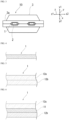
- the adhesive film for metal terminal according to the present disclosure is interposed between a metal terminal electrically connected to an electrode of an electrical storage device element and an exterior material for electrical storage devices for sealing the electrical storage device element.
- an adhesive film 1 for metal terminal according to the present disclosure is interposed between a metal terminal 2 electrically connected to an electrode of an electrical storage device element 4 and an exterior material 3 for electrical storage devices for sealing the electrical storage device element 4.
- the metal terminal 2 protrudes to the outside of the exterior material 3 for electrical storage devices, and is sandwiched between the exterior materials 3 for electrical storage devices with the adhesive film 1 for metal terminal at a peripheral edge portion 3a of the heat-sealed exterior material 3 for electrical storage devices.
- the temperature becomes as high as about 150°C during a hot-pressing step in a manufacturing process of an all-solid-state battery, rapid charging, or the like, and it is required to have tolerance to a temperature of about 150°C.
- a heat-sealable resin layer having a melting point of 150°C or higher for an exterior material 3 for electrical storage devices, and when sides of the exterior materials for electrical storage devices are heat-sealed, the heating temperature is typically in the range of about 160 to 250°C, the pressure is typically in the range of about 0.5 to 2.0 MPa, and a flat plate-shaped metallic seal bar (heat seal bar) is used.
- the temperature is typically in the range of about 160 to 250°C
- the pressure is typically in the range of about 0.5 to 2.0 MPa
- a metallic seal head with a level difference is used in which a level difference for adjusting a difference associated with the thickness of the metal terminal or the adhesive film for metal terminal is provided in a relevant portion of the seal head.
- the temporary bonding step is a step of temporarily fixing the adhesive film for metal terminal to the metal terminal and removing air bubbles
- the main bonding step is a step of bonding the adhesive film for metal terminal to the metal terminal by performing heating and pressurizing one or more times under the condition of a higher temperature over the temporary bonding step.
- the step of temporarily bonding the adhesive film for metal terminal to the metal terminal is performed one or two times, for example, at a temperature of about 160 to 230°C and a pressure of about 0.1 to 0.5 MPa for a time of about 10 to 30 seconds using a metallic seal head covered with heat-resistant rubber having a hardness of about 20 to 50 and a thickness of about 2 to 5 mm, and the main bonding step is performed about one or two times, for example, at a temperature of about 180 to 250°C and a pressure of about 0.2 to 1.0 MPa for a time of about 10 to 20 seconds using a metallic seal head covered with heat-resistant rubber having a hardness of about 20 to 50 and a thickness of about 2 to 5 mm for the purpose of heat-welding between the adhesive film for metal terminal and the metal terminal.
- the welding can be efficiently performed.
- the electrical storage device to which the adhesive film for metal terminal according to the present disclosure is applied is an all-solid-state battery, particularly high temperature and high pressure are applied to the adhesive film for metal terminal.
- the exemplified method for attaching the adhesive film for metal terminal is illustrative, and being limited to a specific method is not intended.
- the pressurization time or the like is appropriately adjusted by, for example, the thickness of the adhesive film for metal terminal.
- the adhesive film 1 for metal terminal is provided for enhancing adhesion between the metal terminal 2 and the exterior material 3 for electrical storage devices. Enhancement of adhesion between the metal terminal 2 and exterior material 3 for electrical storage devices improves the sealing property of the electrical storage device element 4. As described above, the electrical storage device element is sealed such that the metal terminal 2 electrically connected to the electrode of the electrical storage device element 4 protrudes to the outside of the exterior material 3 for electrical storage devices when the electrical storage device element 4 is heat-sealed.
- At least one surface of the adhesive film 1 for metal terminal according to the present disclosure is formed of a resin containing three or more types of constituent units, and has a melting peak temperature of 170°C or higher.
- the constituent unit of a resin means a structural unit forming the resin, and for example, if the resin is a copolymer, at least two types of monomer units are the constituent units of the resin (units of two or more structures introduced into the resin by polymerization).
- the resin containing three or more types of constituent units contains a polyester structure A as described later.
- the polyester structure A is a structure with an ester bond formed by dehydration condensation of a polyvalent carboxylic acid (monomer) and a polyol (monomer), and contains two types of constituent units (monomer units): a structure derived from a polyvalent carboxylic acid (monomer unit (also referred to as a repeating unit)) and a structure derived from a polyol (monomer unit (also referred to as a repeating unit)).
- the upper limit of the number of types of constituent units of the resin containing three or more types of constituent units is not particularly limited, and is, for example, about 6. By using a method such as NMR or GCMS, it is confirmed that the film contains three or more types of constituent units.
- the adhesive film 1 for metal terminal in the present disclosure is formed of a resin containing three or more types of constitutional units (typically, monomer units), the flexibility of the adhesive film 1 for metal terminal is enhanced, and embrittlement in a low-temperature environment is suppressed. Further, since the melting peak temperature of the resin is 170°C or higher, it is possible to suppress deformation in application of a load such as tension to the adhesive film 1 for metal terminal in a high-temperature environment. As a result, the exterior material for electrical storage devices according to the present disclosure can exhibit high sealability not only in a low-temperature environment but also in a high-temperature environment, and also can exhibit high sealing strength in a wide environmental temperature range from a low temperature to a high temperature.
- the constituent unit of the resin is typically a monomer unit contained in the copolymer.
- the constituent unit of the resin is not limited to monomer units forming a main chain of a copolymer, and conceptually includes monomer units forming a side chain (for example, monomer units introduced by graft polymerization or the like), and monomer units forming a crosslinked structure between main chains (units derived from crosslinkable monomers).
- the resin for forming at least one surface of the adhesive film 1 for metal terminal contains the polyester structure A.
- the polyester structure A is obtained by condensation polymerization of an acid component and a polyol component.
- the acid component is selected from phthalic acid, terephthalic acid, isophthalic acid, naphthalenedicarboxylic acid, cyclohexanedicarboxylic acid, adipic acid, sebacic acid and the like.
- the polyol component is selected from ethylene glycol, butanediol, pentanediol, hexanediol, neopentyl glycol, diethylene glycol, polytetramethylene glycol, cyclohexanedimethanol, propanediol and the like.
- the polyester structure A is more preferably a polybutylene terephthalate structure.
- the polybutylene terephthalate structure is a structure formed by polymerizing terephthalic acid and 1,4-butanediol, and contains two types of constituent units: a structure derived from terephthalic acid and a structure derived from 1,4-butanediol.
- the resin for forming at least one surface of the adhesive film 1 for metal terminal contains at least one selected from the group consisting of a polyether structure and a polyester structure B, in addition to the polyester structure A.
- the polyester structure B is a polyester structure different from the polyester structure A.
- the polyether structure can be formed by introducing a compound (monomer) having a polyether structure into a resin.
- Examples of the method for introducing a polyether structure into a resin include a method using a compound having a polyether structure as a polyvalent carboxylic acid, and a method using a compound having a polyether structure as a polyol that reacts with a polyvalent carboxylic acid.
- the polyether structure form a soft segment of the resin in the film, and examples of the compound (monomer) that forms such a soft segment by undergoing a polycondensation reaction with a polyvalent carboxylic acid of the polyester structure A include diols capable of exhibiting elasticity, such as polytetramethylene ether glycol and neopentyl glycol.
- the polyether structure is preferably a polyether structure derived from at least one selected from the group consisting of polytetramethylene ether glycol and neopentyl glycol. Polytetramethylene ether glycol, neopentyl glycol and the like form constitutional units in the polyether structure of the resin.
- the polyester structure B can be introduced into a resin by using a compound (monomer) that forms a polyester structure by undergoing a polycondensation reaction with a polyol used in the polyester structure A, such as ethylene glycol, butanediol, pentanediol, hexanediol, neopentyl glycol, diethylene glycol, polytetramethylene glycol, cyclohexanedimethanol or propanediol.
- a compound (monomer) that forms a polyester structure by undergoing a polycondensation reaction with a polyol used in the polyester structure A, such as ethylene glycol, butanediol, pentanediol, hexanediol, neopentyl glycol, diethylene glycol, polytetramethylene glycol, cyclohexanedimethanol or propanediol.
- polyester structure B form a soft segment of a resin in the film
- examples of the compound (monomer) that forms such a soft segment by undergoing a polycondensation reaction with a polyol of the polyester structure A include dicarboxylic acids such as aromatic dicarboxylic acids such as phthalic acid, terephthalic acid, isophthalic acid and naphthalenedicarboxylic acid, and aliphatic dicarboxylic acids such as aliphatic dicarboxylic acids such as adipic acid, sebacic acid, dodecanedionic acid and cyclohexanedicarboxylic acid (preferably aliphatic dicarboxylic acids having 4 to 20 carbon atoms).
- dicarboxylic acids such as aromatic dicarboxylic acids such as phthalic acid, terephthalic acid, isophthalic acid and naphthalenedicarboxylic acid
- aliphatic dicarboxylic acids such as aliphatic dicarboxylic acids
- the polyester structure B is particularly preferably a polyester structure obtained by polycondensation of a polyol and at least one dicarboxylic acid selected from the group consisting of isophthalic acid, sebacic acid and dodecanedionic acid.
- the resin for forming at least one surface of the adhesive film 1 for metal terminal contains a polyether structure in addition to the polybutylene terephthalate structure, and the polyether structure has a polycondensation structure of at least one of polytetramethylene ether glycol and neopentyl glycol and terephthalic acid of the polybutylene terephthalate structure.
- the resin contains the polyester structure B in addition to the polybutylene terephthalate structure, and the polyester structure B has a polycondensation structure of at least one selected from the group consisting of isophthalic acid, dodecanedionic acid and sebacic acid and 1,4-butanediol of the polybutylene terephthalate structure.
- the resin for forming at least one surface of the adhesive film 1 for metal terminal contains the polyester structure A as a main component, and it is more preferable that the resin for forming the film contains the polybutylene terephthalate structure as a main component.
- the main component means that the proportion of the component is 50 mol% or more, preferably 60 mol% or more, more preferably 70 mol% or more, still more preferably 80 mol% or more when the proportion of all components forming the resin is 100 mol%.
- the proportion of at least one of the polyether structure and the dicarboxylic acid structure is preferably about 2 to 30 mol%, more preferably about 3 to 25 mol%, still more preferably about 3 to 20 mol% when the proportion of all components (all monomer units) forming the resin is 100 mol%.
- the resin for forming at least one surface of the adhesive film 1 for metal terminal has a melting peak temperature of 170°C or higher.
- the melting peak temperature is preferably 190°C or higher, more preferably 200°C or higher, and preferably 350°C or lower, more preferably 300°C or lower, still more preferably 270°C or lower, still more preferably 217°C or lower, and is preferably in the range of about 170 to 350°C, about 170 to 300°C, about 170 to 270°C, about 170 to 217°C, about 190 to 350°C, about 190 to 300°C, about 190 to 270°C, about 190 to 217°C, about 200 to 350°C, about 200 to 300°C, about 200 to 270°C, about 200 to 217°C, or the like.
- the melting peak temperature is not excessively high.
- the melting peak temperature in these ranges is lower than that of a heat-resistant film commonly usable as a front base material (that is, a base material layer outside an exterior material for electrical storage devices), and enables sealing without melting the front base material. Further, it is also possible to maintain intended heat resistance (sealing strength in an environment at about 150°C).
- the melting peak temperature of the resin for forming at least one surface of the adhesive film 1 for metal terminal is measured in accordance with the provisions of JIS K 7121: 2012 (Testing Methods for Transition Temperatures of Plastics (Amendment 1 of JIS K 7121: 1987)). The measurement is performed with a differential scanning calorimeter (DSC, Differential Scanning Calorimeter Q200 manufactured by TA Instruments). The measurement sample is held at -50°C for 15 minutes, then heated from -50°C to 300°C at a temperature rise rate of 10°C/min to measure the first melting peak temperature P (°C), and then held at 300°C for 2 minutes.
- DSC Differential Scanning Calorimeter Q200 manufactured by TA Instruments
- the measurement sample is cooled from 300°C to -50°C at a temperature lowering rate of 10°C/min, and held for 15 minutes.
- the second melting peak temperature Q (°C) is measured by heating the measurement sample from -50°C to 300°C at a temperature rise rate of 10°C/min.
- the flow rate of the nitrogen gas is set to 50 ml/min.
- the first measured melting peak temperature P (°C) and the second measured melting peak temperature Q (°C) are determined, and the first measured melting peak temperature P is adopted as a melting peak temperature.
- the glass transition temperature (Tg) of the resin for forming at least one surface of the adhesive film 1 for metal terminal is preferably 67°C or lower, preferably 60°C or lower, still more preferably 50°C or lower, and preferably 0°C or higher, more preferably 10°C or higher, and is preferably in the range of about 0 to 67 °C, about 0 to 60 °C, about 0 to 50 °C, about 10 to 67 °C, about 10 to 60 °C, about 10 to 50 °C, or the like.
- the glass transition temperature (Tg) is measured by dynamic mechanical analysis (DMA).
- the glass transition temperature of the resin is measured by dynamic mechanical analysis (DMA).
- DMA dynamic mechanical analysis
- the measurement is performed using a commercially available apparatus.
- a resin cut into 5 mm in width and 20 mm in length is set in chucks with the chuck-to-chuck distance being 10 mm.
- the temperature is elevated from -30°C to 250°C at a temperature elevation rate of 5°C/min, the frequency is 10 Hz, the static load is 70 g, and the strain is 5 ⁇ m.
- the temperature at a peak of a loss sine (tan ⁇ ) obtained by dividing a loss elastic modulus by a storage elastic modulus is taken as a glass transition temperature.
- the glass transition temperature (Tg) of the resin for forming at least one surface of the adhesive film 1 for metal terminal can be lowered by, for example, increasing the proportion of a copolymerization component (in particular, a portion that is not a polyester structure A (a polyester structure B, or a soft segment such as a polyether structure)) of the resin.
- a copolymerization component in particular, a portion that is not a polyester structure A (a polyester structure B, or a soft segment such as a polyether structure) of the resin.
- the indentation elastic modulus from at least one surface of the adhesive film 1 for metal terminal is preferably about 0.3 GPa or more, more preferably about 0.4 GPa or more, still more preferably about 0.5 GPa or more.
- the indentation elastic modulus is preferably about 5 GPa or less, more preferably about 4 GPa or less, still more preferably about 3 GPa or less, still more preferably about 2 GPa or less, still more preferably 1.5 GPa or less.
- the indentation elastic modulus is preferably in the range of about 0.3 to 5 GPa, about 0.3 to 4 GPa, about 0.3 to 3 GPa, about 0.3 to 2 GPa, about 0.3 to 1.5 GPa, about 0.4 to 5 GPa, about 0.4 to 4 GPa, about 0.4 to 3 GPa, about 0.4 to 2 GPa, about 0.4 to 1.5 GPa, about 0.5 to 5 GPa, about 0.5 to 4 GPa, about 0.5 to 3 GPa, about 0.5 to 2 GPa, or about 0.5 to 1.5 GPa.
- the method for measuring the indentation elastic modulus is as follows.
- the indentation elastic modulus is measured in conformation to ISO 14577: 2015, where a method is used in which the indentation elastic modulus is measured on a surface of the adhesive film 1 for metal terminal (a surface formed of the resin containing three or more types of constituent units) in an environment at about 23°C and about 60% RH using a load ultra-microhardness tester equipped with a Vickers indenter (quadrilateral diamond indenter with a facing angle of 136 °). The measurement is performed with an indentation speed of 0.1 ⁇ m/sec, a depth of indentation of 2 ⁇ m, a holding time of 5 seconds and a drawing speed of 0.1 ⁇ m/sec.
- the load ultra-microhardness tester is preferably PICODENTOR HM 500 (manufactured by FISCHER INSTRUMENTS K.K.). At least five samples are measured, and the average of the measured values is taken as a value of the indentation elastic modulus under the conditions. It is desirable to use a suction board or an instantaneous adhesive for fixing the sample. The measurement is performed on a central portion of one main surface of the adhesive film 1 for metal terminal (a surface formed of the resin containing three or more types of constituent units).
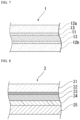
- the adhesive film 1 for metal terminal a layer formed of the resin containing three or more types of constituent units (hereinafter, sometimes referred to as a resin layer A) forms at least one surface. That is, the adhesive film 1 for metal terminal according to the present disclosure includes at least one resin layer A, and at least one of the surfaces of the adhesive film 1 for metal terminal is formed of the resin layer A. As long as the effect of the present disclosure is exhibited, the adhesive film 1 for metal terminal according to the present disclosure may have a single layer as shown in Fig. 4 , or multiple layers as shown in Figs. 5 to 7 .
- the adhesive film 1 for metal terminal is formed of the resin layer A, and a surface on the metal terminal side and a surface of the exterior material for electrical storage devices are formed of the resin layer A.
- the resin for forming a surface of the adhesive film 1 for metal terminal on the side of the exterior material for electrical storage devices and the resin for forming a surface of the adhesive film 1 for metal terminal on the metal terminal side are the same resin (that is, the resin for forming the resin layer A).
- the adhesive film 1 for metal terminal according to the present disclosure has multiple layers, at least one layer may be formed of the resin layer A.
- the adhesive film 1 for metal terminal according to the present disclosure has a two-layer structure as shown in Fig. 5 , the adhesive film 1 for metal terminal is a laminate of a first resin layer 12a and a second resin layer 12b, and at least one of these layers is formed of the resin layer A.
- the resin forming a surface on the side of the exterior material for electrical storage devices and the resin forming a surface on the metal terminal side are the same resin.
- the adhesive film 1 for metal terminal when the adhesive film 1 for metal terminal according to the present disclosure has a three-layer structure as shown in Fig. 6 , the adhesive film 1 for metal terminal is a laminate in which the first resin layer 12a, an intermediate layer 11 and the second resin layer 12b are laminated in this order, and among these layers, at least one of the first resin layer 12a and the second resin layer 12b includes the resin layer A.
- the intermediate layer 11 is preferably excellent in heat resistance, and when a higher priority is placed on insulation quality, the melting point of the intermediate layer 11 is preferably 250°C or higher, and more preferably 250 to 330°C.
- the melting point of the intermediate layer 11 is an endothermic peak measured with a differential scanning calorimeter (DSC).
- the adhesive film 1 for metal terminal according to the present disclosure may include four or more layers.
- an adhesion promoter layer 13 may be laminated between the first resin layer 12a and the intermediate layer 11 and between the second resin layer 12b and the intermediate layer 11.
- the first resin layer 12a is disposed on the metal terminal side
- the second resin layer 12b is disposed on the side of the exterior material 3 for electrical storage devices.
- the metal terminal-side surface of the adhesive film 1 for metal terminal according to the present disclosure has heat sealability to a metal (metal forming a metal terminal), and the surface on the side of the exterior material for electrical storage devices has heat sealability to a heat-sealable resin layer described later. It is preferable that the surface on the metal terminal side is formed of the resin layer A. It is also preferable that the surface on the side of the exterior material for electrical storage devices is formed of the resin layer A.
- the type of the different resin is not particularly limited as long as the purpose of the adhesive film for metal terminal according to the present disclosure is not hindered.
- the different resin include polyethylene terephthalate, polyethylene naphthalate, polybutylene terephthalate, polyacetal, acrylic resins, homo- or block-type polypropylene, cyclic polyolefins, polymethylpentene and copolymers thereof with ⁇ -olefins, nylon 6, nylon 66, polyvinylidene chloride, polyphenylene sulfide, acetyl cellulose, fluorine-based resins such as ETFE, PCTFE, PFA and FEP, and these resins subjected to modification with maleic anhydride or acrylic acid.
- the resin layer A may contain one type or two or more types of different resins.
- thermoplastic elastomer selected from polyester-based elastomers, polyamide-based elastomers, polyurethane-based elastomers, polyolefin-based elastomers, polystyrene-based elastomers, polyether-based elastomers, and acryl-based elastomers, or a copolymer of any of these thermoplastic elastomers.
- the elastomer is more preferably a thermoplastic elastomer including a block copolymer of polybutylene terephthalate and polyether, and a thermoplastic elastomer including an ⁇ -olefin copolymer of polymethylpentene.
- the thickness of the resin layer A is preferably about 20 ⁇ m or more, more preferably about 30 ⁇ m or more, still more preferably about 50 ⁇ m or more. From the same view point, the thickness is preferably about 300 ⁇ m or less, more preferably about 200 ⁇ m or less, still more preferably about 100 ⁇ m or less. The thickness is preferably in the range of about 20 to 300 ⁇ m, about 20 to 200 ⁇ m, about 20 to 100 ⁇ m, about 30 to 300 ⁇ m, about 30 to 200 ⁇ m, about 30 to 100 ⁇ m, about 50 to 300 ⁇ m, about 50 to 200 ⁇ m, or about 50 to 100 ⁇ m.
- the adhesive film 1 for metal terminal according to the present disclosure can include at least one other resin layer different from the resin layer A.
- the other resin layer has a melting point of 150°C or higher.
- the melting point of the other resin layer is preferably about 150 to 330°C, more preferably about 160 to 280°C.
- the melting point of the other resin layer is an endothermic peak measured with a differential scanning calorimeter (DSC).
- the compositions of the other resin layers may be the same or different.
- the compositions of the resin layers A may be the same or different.
- the thickness of the other resin layer is preferably about 20 ⁇ m or more, more preferably about 50 ⁇ m or more, still more preferably about 80 ⁇ m or more. From the same view point, the thickness is preferably about 300 ⁇ m or less, more preferably about 200 ⁇ m or less, still more preferably about 100 ⁇ m or less. The thickness is preferably in the range of about 20 to 300 ⁇ m, about 20 to 200 ⁇ m, about 20 to 100 ⁇ m, about 50 to 300 ⁇ m, about 50 to 200 ⁇ m, about 50 to 100 ⁇ m, about 80 to 300 ⁇ m, about 80 to 200 ⁇ m, or about 80 to 100 ⁇ m.
- examples of the laminated configuration of the adhesive film 1 for metal terminal include laminates in which the first resin layer 12a in Fig. 5 is the resin layer A and the second resin layer 12b is the other resin layer; laminates in which the second resin layer 12b in Fig. 5 is the resin layer A and the first resin layer 12a is the other resin layer; laminates in which the first resin layer 12a in Fig 6 or 7 is the resin layer A and the intermediate layer 11 and the second resin layer 12b are other resin layers; laminates in which the second resin layer 12b in Fig.
- the resin for forming the other resin layer is not particularly limited as long as the purpose of the adhesive film for metal terminal according to the present disclosure is not hindered, and examples thereof include polyolefin-based resins (polypropylene, acid-modified polypropylene and the like), polyamide-based resins, polyester-based resins, epoxy resins, acrylic resins, fluororesins, silicone resins, phenol resins, polyetherimide, polyimide, polycarbonate, and mixtures and copolymers thereof, and polyethylene terephthalate, polyethylene naphthalate, polyphenylene sulfide, polyetheretherketone, polyimide and the like are particularly preferable because they are excellent in heat resistance.
- polyolefin-based resins polypropylene, acid-modified polypropylene and the like
- polyamide-based resins polyester-based resins
- epoxy resins acrylic resins, fluororesins, silicone resins
- phenol resins polyetherimide
- polyimide polyimide
- Each of the resin layer A and the other resin layer may further contain additives such as a filler if necessary.
- a filler When a filler is contained, a short circuit between the metal terminal 2 and a barrier layer 33 of the exterior material 3 for electrical storage devices can be effectively suppressed because the filler functions as a spacer.
- the particle size of the filler is in the range of about 0.1 to 35 ⁇ m, preferably about 5.0 to 30 ⁇ m, more preferably about 10 to 25 ⁇ m.
- the content of the filler based on 100 parts by mass of resin components forming the resin layer A and the other resin layer is about 5 to 30 parts by mass, more preferably about 10 to 20 parts by mass.
- an inorganic filler or an organic filler can be used as the filler.
- the inorganic filler include carbon (carbon, graphite), silica, aluminum oxide, barium titanate, iron oxide, silicon carbide, zirconium oxide, zirconium silicate, magnesium oxide, titanium oxide, calcium aluminate, calcium hydroxide, aluminum hydroxide, magnesium hydroxide and calcium carbonate.
- the organic filler include fluororesins, phenol resins, urea resins, epoxy resins, acrylic resins, benzoguanamine-formaldehyde condensates, melamine-formaldehyde condensates, crosslinked products of polymethyl methacrylate, and crosslinked products of polyethylene.
- Each of the resin layer A and the other resin layer may further contain a pigment if necessary.
- a pigment various inorganic pigments can be used.
- carbon (carbon, graphite) exemplified as the filler can be preferably exemplified.
- Carbon (carbon, graphite) is a material generally used inside an electrical storage device, and there is no possibility of being dissolved in an electrolytic solution.
- the carbon has a high coloring effect, allows a sufficient coloring effect to be obtained with an addition amount small enough not to hinder bondability, is not melted by heat, and is capable of increasing the apparent melt viscosity of the resin added. Further, it is possible to impart an excellent sealing property between the exterior material for electrical storage devices and the metal terminal by preventing a pressed portion from being thinned during thermal bonding (heat-sealing).
- the addition amount of the pigment based on 100 parts by mass of resin components for forming the resin layer A and the other resin layer is about 0.05 to 0.3 parts by mass, preferably about 0.1 to 0.2 parts by mass, when carbon black having a particle size of about 0.03 ⁇ m is used.
- the adhesion promoter layer 13 is a layer provided if necessary for the purpose of firmly bonding the intermediate layer 11 to the first resin layer 12a, and the intermediate layer 11 to the second resin layer 12b (see Fig. 7 ).
- the adhesion promoter layer 13 may be provided between the intermediate layer 11 and the first resin layer 12a and/or between the intermediate layer 11 and the second resin layer 12b.
- the adhesion promoter layer 13 can be formed using a known adhesion promoter such as an isocyanate-based adhesion promoter, a polyethyleneimine-based adhesion promoter, a polyester-based adhesion promoter, a polyurethane-based adhesion promoter or a polybutadiene-based adhesion promoter. From the viewpoint of obtaining high adhesion strength, it is preferable that the adhesion promoter layer is formed of an isocyanate-based adhesion promoter, among the above-mentioned adhesion promoters.
- the isocyanate-based adhesion promoter one composed of an isocyanate component selected from a triisocyanate monomer and polymeric MDI is excellent in lamination strength and undergoes little decrease in lamination strength at a high temperature.
- adhesion promoter layer from tris(p-isocyanatephenyl)thiophosphate which is a triisocyanate monomer, or a two-liquid curable adhesion promoter contain a polyethyleneimine-based resin as a main component and polycarbodiimide as a crosslinking agent.
- the adhesion promoter layer 13 can be formed by performing coating by a known coating method such as a bar coating method, a roll coating method or a gravure coating method, and drying.
- the coating amount of the adhesion promoter is about 20 to 100 mg/m 2 , preferably about 40 to 60 mg/m 2 in the case of an adhesion promoter composed of triisocyanate, about 40 to 150 mg/m 2 , preferably about 60 to 100 mg/m 2 in the case of an adhesion promoter composed of polymeric MDI, and about 5 to 50 mg/m 2 , preferably about 10 to 30 mg/m 2 in the case of a two-liquid curable adhesion promoter containing polyethyleneimine as a main component and polycarbodiimide as a crosslinking agent.
- the triisocyanate monomer is a monomer having three isocyanate groups per molecule
- the polymeric MDI is a mixture of MDI and a MDI oligomer obtained by polymerizing MDI, and is represented
- the total thickness of the adhesive film 1 for metal terminal according to the present disclosure is preferably about 50 ⁇ m or more, more preferably about 80 ⁇ m or more, still more preferably about 100 ⁇ m or more. From the same view point, the thickness is preferably about 500 ⁇ m or less, more preferably about 300 ⁇ m or less, and preferably about 200 ⁇ m or less. The thickness is preferably in the range of about 50 to 500 ⁇ m, about 50 to 300 ⁇ m, about 50 to 200 ⁇ m, about 80 to 500 ⁇ m, about 80 to 300 ⁇ m, about 80 to 200 ⁇ m, about 100 to 500 ⁇ m, about 100 to 300 ⁇ m, or about 100 to 200 ⁇ m.
- the adhesive film 1 for metal terminal according to the present disclosure can be formed into a film shape by a known method such as an extrusion lamination method, a T-die method, an inflation method, or a thermal lamination method using a resin for forming the resin layer A (a resin containing homopolybutylene terephthalate).
- a resin for forming the resin layer A a resin containing homopolybutylene terephthalate
- the layers may be laminated by a co-extrusion-type extruder.
- an adhesion promoter that forms the adhesion promoter layer 13 may be applied on the intermediate layer 11 and dried by the above-described method, followed by lamination of each of the first resin layer 12a and the second resin layer 12b on the adhesion promoter layer 13.
- the method for interposing the adhesive film 1 for metal terminal between the metal terminal 2 and the exterior material 3 for electrical storage devices is not particularly limited, and for example, as shown in Figs. 1 to 3 , the adhesive film 1 for metal terminal may be disposed on the metal terminal 2 at a portion where the metal terminal 2 is sandwiched between the exterior materials 3 for electrical storage devices. In addition, the adhesive film 1 for metal terminal may be disposed on both sides of the metal terminal 2 so as to cross the two metal terminals 2 in a portion where the metal terminal 2 is sandwiched between the exterior materials 3 for electrical storage devices.
- the adhesive film 1 for metal terminal according to the present disclosure is interposed between the metal terminal 2 and the exterior material 3 for electrical storage devices.
- the metal terminal 2 (tab) is a conductive member electrically connected to an electrode (positive electrode or negative electrode) of the electrical storage device element 4, and is composed of a metal material.
- the metal material that forms the metal terminal 2 is not particularly limited, and examples thereof include aluminum, nickel, and copper.
- the metal terminal 2 connected to a positive electrode of a lithium ion electrical storage device is typically composed of aluminum or the like.
- the metal terminal 2 connected to the negative electrode of the lithium ion electrical storage device is typically formed of copper, nickel or the like, and is formed of copper plated with nickel, a clad material of nickel and copper or the like from the viewpoint of low resistance and prevention of surface degradation.
- the surface of the metal terminal 2 is subjected to chemical conversion treatment.
- the chemical conversion treatment include a known method in which a corrosion-resistant film of a phosphate, a chromate, a fluoride, a triazinethiol compound, an acrylate or the like.
- phosphoric acid chromate treatment using a material including three components: a phenol resin, a chromium (III) fluoride compound and phosphoric acid or three components: an acrylic resin, chromium (III) nitrate and phosphoric acid are preferred.
- the size of the metal terminal 2 may be appropriately set according to the size of an electrical storage device used.
- the thickness of the metal terminal 2 is preferably about 50 to 1000 ⁇ m, more preferably about 70 to 800 ⁇ m.
- the length of the metal terminal 2 is preferably about 1 to 200 mm, more preferably about 3 to 150 mm.
- the width of the metal terminal 2 is preferably about 1 to 200 mm, more preferably about 3 to 150 mm.
- Examples of the exterior material 3 for electrical storage devices include materials having a laminated structure including a laminate having at least a base material layer 31, a barrier layer 33, and a heat-sealable resin layer 35 in the stated order.
- Fig. 8 shows an aspect in which the base material layer 31, an adhesive agent layer 32 provided if necessary, the barrier layer 33, an adhesive layer 34 provided if necessary, and the heat-sealable resin layer 35 are laminated in the stated order as an example of a cross-sectional structure of the exterior material 3 for electrical storage devices.
- the base material layer 31 is on the outer layer side
- the heat-sealable resin layer 35 is an innermost layer.
- Figs. 1 to 3 show the electrical storage device 10 where the embossed-type exterior material 3 for electrical storage devices, which is molded by embossing molding, is used, but the exterior material 3 for electrical storage devices may be of non-molded pouch type. Examples of the pouch type include three-way seal, four-way seal and pillow type, and any of the types may be used.
- the thickness of the laminate forming the exterior material 3 for electrical storage devices is not particularly limited, and the upper limit is preferably about 180 ⁇ m or less, about 160 ⁇ m or less, about 155 ⁇ m or less, about 140 ⁇ m or less, about 130 ⁇ m or less, or about 120 ⁇ m or less from the viewpoint of cost reduction, improvement of the energy density and the like, and the lower limit is preferably about 35 ⁇ m or more, about 45 ⁇ m or more, about 60 ⁇ m or more, or about 80 ⁇ m or more from the viewpoint of maintaining the function of the exterior material 3 for electrical storage devices, i.e., a function of protecting the electrical storage device element 4.
- the thickness is preferably in the range of about 35 to 180 ⁇ m, about 35 to 160 ⁇ m, about 35 to 155 ⁇ m, about 35 to 140 ⁇ m, about 35 to 130 ⁇ m, about 35 to 120 ⁇ m, about 45 to 180 ⁇ m, about 45 to 160 ⁇ m, about 45 to 155 ⁇ m, about 45 to 140 ⁇ m, about 45 to 130 ⁇ m, about 45 to 120 ⁇ m, about 60 to 180 ⁇ m, about 60 to 160 ⁇ m, about 60 to 155 ⁇ m, about 60 to 140 ⁇ m, about 60 to 130 ⁇ m, about 60 to 120 ⁇ m, about 80 to 180 ⁇ m, about 80 to 160 ⁇ m, about 80 to 155 ⁇ m, about 80 to 140 ⁇ m, about 80 to 130 ⁇ m or about 80 to 120 ⁇ m.
- the adhesive film 1 for metal terminal can be suitably applied to an exterior material for an all-solid-state battery, and the thickness of the laminate forming the exterior material for the all-solid-state battery is not particularly limited, and is preferably about 10,000 ⁇ m or less, about 8,000 ⁇ m or less, or about 5,000 ⁇ m or less from the viewpoint of cost reduction, improvement of the energy density and the like, and preferably about 100 ⁇ m or more, about 150 ⁇ m or more, or about 200 ⁇ m or more from the viewpoint of maintaining the function of the exterior material for an all-solid-state battery of protecting a battery element.
- the thickness of the laminate is preferably, in the range of, for example, about 100 to 10,000 ⁇ m, about 100 to 8,000 ⁇ m, about 100 to 5,000 ⁇ m, about 150 to 10,000 ⁇ m, about 150 to 8,000 ⁇ m, about 150 to 5,000 ⁇ m, about 200 to 10,000 ⁇ m, about 200 to 8,000 ⁇ m, or about 200 to 5,000 ⁇ m, and particularly preferably about 100 to 500 ⁇ m.
- the base material layer 31 is a layer that functions as a base material of the exterior material for electrical storage devices, and forms the outermost layer side of the exterior material for electrical storage devices.
- the material that forms the base material layer 31 is not particularly limited as long as it has an insulation quality.
- Examples of the material that forms the base material layer 31 include polyester, polyamide, epoxy, acrylic, fluororesins, polyurethane, silicone resins, phenol, polyetherimide, polyimide and mixtures and copolymers thereof.
- Polyester such as polyethylene terephthalate or polybutylene terephthalate has the advantage that it is excellent in electrolytic solution resistance, so that whitening etc. due to deposition of an electrolytic solution hardly occurs, and thus the polyester is suitably used as a material for formation of the base material layer 31.
- a polyamide film is excellent in stretchability, can prevent occurrence of whitening due to resin breakage in the base material layer 31 during molding, and is thus suitably used as a material for formation of the base material layer 31.
- the base material layer 31 may be formed of a uniaxially or biaxially stretched resin film, or may be formed of an unstretched resin film. Among them, a uniaxially or biaxially stretched resin film, particularly a biaxially stretched resin film has improved heat resistance through orientation and crystallization, and is therefore suitably used as the base material layer 31.
- nylons and polyesters are preferable and biaxially stretched nylons and biaxially stretched polyesters are more preferable as resin films for formation of the base material layer 31. Since the all-solid-state battery has tolerance to a temperature of 150°C or higher, sealing is often performed at a high temperature of 200°C or higher, and biaxially stretched polyester is most suitable.
- the base material layer 31 can also be laminated with a resin film which is made of a different material for improving pinhole resistance, and insulation quality as a packaging of an electrical storage device.
- a resin film which is made of a different material for improving pinhole resistance, and insulation quality as a packaging of an electrical storage device.
- Specific examples include a multi-layered structure in which a polyester film and a nylon film are laminated, and a multi-layered structure in which a biaxially stretched polyester and a biaxially stretched nylon are laminated.
- the resin films may be bonded with the use of an adhesive, or may be directly laminated without the use of an adhesive.
- Examples of the method for bonding the resin films without the use of an adhesive include methods in which the resin films are bonded in a heat-melted state, such as a co-extrusion method, a sand lamination method and a thermal lamination method.
- a co-extrusion method such as a co-extrusion method, a sand lamination method and a thermal lamination method.
- at least the outermost layer be a biaxially stretched polyester.
- the friction of the base material layer 31 may be reduced for improving moldability.
- the friction coefficient of the surface thereof is not particularly limited, and it is, for example, 1.0 or less.
- the method for reducing the friction of the base material layer 31 include matting treatment, formation of a thin film layer of a slipping agent, and a combination thereof.
- the thickness of the base material layer 31 is, for example, about 10 to 50 ⁇ m, preferably about 15 to 30 ⁇ m.
- the adhesive agent layer 32 is a layer disposed on the base material layer 31 if necessary for imparting adhesion to the base material layer 31. That is, the adhesive agent layer 32 is provided between the base material layer 31 and the barrier layer 33.
- the adhesive agent layer 32 is formed from an adhesive capable of bonding the base material layer 31 and the barrier layer 33.
- the adhesive used for forming the adhesive agent layer 32 may be a two-liquid curable adhesive, or may be a one-liquid curable adhesive.
- the adhesion mechanism of the adhesive used for forming the adhesive agent layer 32 is not particularly limited, and may be any one of a chemical reaction type, a solvent volatilization type, a heat melting type, a heat pressing type and so on.
- polyurethane-based two-liquid curable adhesive agents As resin components of adhesives that can be used for formation of the adhesive agent layer 32, polyurethane-based two-liquid curable adhesive agents; and polyamides, polyesters or blend resins of these resins and modified polyolefins are preferable because they are excellent in spreadability, durability and a yellowing inhibition action under high-humidity conditions, a thermal degradation inhibition action during heat-sealing, and so on, and effectively suppress occurrence of delamination by inhibiting a reduction in lamination strength between the base material layer 31 and the barrier layer 33.
- the adhesive agent layer 32 may be made multilayered with different adhesive components.
- a resin excellent in bondability to the base material layer 31 is selected as an adhesive component to be disposed on the base material layer 31 side
- an adhesive component excellent in bondability to the barrier layer 33 is selected as an adhesive component to be disposed on the barrier layer 33 side, from the viewpoint of improving lamination strength between the base material layer 31 and the barrier layer 33.
- the adhesive agent layer 32 is made multilayered with different adhesive components
- specific examples of the preferred adhesive component to be disposed on the barrier layer 33 side include acid-modified polyolefins, metal-modified polyolefins, mixed resins of polyesters and acid-modified polyolefins, and resins containing a copolymerization polyester.
- the thickness of the adhesive agent layer 32 is, for example, about 2 to 50 ⁇ m, preferably about 3 to 25 ⁇ m.
- the barrier layer 33 is a layer which is intended to improve the strength of the exterior material for electrical storage devices and which has a function of preventing ingress of water vapor, oxygen, light and the like into the electrical storage device.
- the barrier layer 33 is preferably a metal layer, i.e. a layer formed of a metal. Specific examples of the metal forming the barrier layer 33 include aluminum, stainless and titanium, with aluminum being preferred.
- the barrier layer 33 can be formed from, for example, a metal foil, a metal vapor-deposited film, an inorganic oxide vapor-deposited film, a carbon-containing inorganic oxide vapor-deposited film, a film provided with any of these vapor-deposited films, or the like, and is formed preferably from a metal foil, more preferably from an aluminum foil.
- the barrier layer From the viewpoint of preventing generation of wrinkles and pinholes in the barrier layer 33 during manufacturing of the exterior material for electrical storage devices, it is more preferable to form the barrier layer from a soft aluminum foil such as annealed aluminum (JIS H4160: 1994 A8021H-O, JIS H4160: 1994 A8079H-O, JIS H4000:2014 A8021P-O, JIS H4000:2014 A8079P-O).
- a soft aluminum foil such as annealed aluminum
- the thickness of the barrier layer 33 is preferably about 9 to 200 ⁇ m, more preferably about 20 to 45 ⁇ m, about 45 to 65 ⁇ m or about 65 to 85 ⁇ m, more preferably about 20 to 100 ⁇ m, from the viewpoint of making pinholes less likely to be generated by molding while thinning the exterior material for electrical storage devices.
- the barrier layer 33 are subjected to a chemical conversion treatment for stabilization of bonding, prevention of dissolution and corrosion, and so on.
- the chemical conversion treatment is a treatment for forming a corrosion-resistant film on the surface of the barrier layer.
- the adhesive layer 34 is a layer provided between the barrier layer 33 and the heat-sealable resin layer 35 if necessary for firmly bonding the heat-sealable resin layer 35.
- the adhesive layer 34 is formed from an adhesive capable of bonding the barrier layer 33 and the heat-sealable resin layer 35 to each other.
- the composition of the adhesive used for forming the adhesive layer is not particularly limited, and examples thereof include adhesives formed of a polyester polyol compound and an alicyclic isocyanate compound.
- the thickness of the adhesive layer 34 is, for example, about 1 to 40 ⁇ m, preferably about 2 to 30 ⁇ m.
- the heat-sealable resin layer 35 is a layer which corresponds to an innermost layer and performs a function of hermetically sealing the electrical storage device element by heat-sealing the heat-sealable resin layers to each other during construction of the electrical storage device.
- the resin component to be used in the heat-sealable resin layer 35 is not particularly limited as long as it can be heat-sealed, and for the exterior material for electrical storage devices, examples thereof generally include polyolefins and cyclic polyolefins.
- polystyrene resin examples include polyethylene such as low-density polyethylene, medium-density polyethylene, high-density polyethylene and linear low-density polyethylene; crystalline or noncrystalline polypropylene such as homopolypropylene, block copolymers of polypropylene (e.g., block copolymers of propylene and ethylene) and random copolymers of polypropylene (e.g., random copolymers of propylene and ethylene); terpolymers of ethylene-butene-propylene; and the like.
- polyethylene and polypropylene are preferred.
- the cyclic polyolefin is a copolymer of an olefin and a cyclic monomer
- examples of the olefin as a constituent monomer of the cyclic polyolefin include ethylene, propylene, 4-methyl-1-pentene, butadiene and isoprene.
- examples of the cyclic monomer as a constituent monomer of the cyclic polyolefin include cyclic alkenes such as norbornene, specifically cyclic dienes such as cyclopentadiene, dicyclopentadiene, cyclohexadiene and norbornadiene.
- cyclic alkenes are preferable, and norbornene is further preferable.
- Examples of the constituent monomer include styrene.
- crystalline or noncrystalline polyolefins, cyclic polyolefins and blend polymers thereof are preferable, and polyethylene, polypropylene, copolymers of ethylene and norbornene, and blend polymers of two or more thereof are more preferable.
- the heat-sealable resin layer 35 may be formed from one resin component alone, or may be formed from a blend polymer obtained by combining two or more resin components. Further, the heat-sealable resin layer 35 may have only one layer, but may have two or more layers formed of the same resin component or different resin components.
- the thickness of the heat-sealable resin layer 35 is not particularly limited, and is, for example, about 2 to 2000 ⁇ m, preferably about 5 to 1000 ⁇ m, still more preferably about 10 to 500 ⁇ m.
- the adhesive film 1 for metal terminal according to the present disclosure can be particularly suitably applied to an exterior material for an all-solid-state battery, and the melting point of the heat-sealable resin layer 35 of the exterior material for an all-solid-state battery is preferably 150 to 250°C, more preferably 180 to 270°C, still more preferably 200 to 270°C, still more preferably 200 to 250°C.
- Examples of the resin contained in the heat-sealable resin layer 35 of the exterior material for an all-solid-state battery include polyolefins such as polypropylene and polyethylene, acid-modified polyolefins such as acid-modified polypropylene and acid-modified polyethylene, and polybutylene terephthalate.
- polybutylene terephthalate is excellent in heat resistance, and therefore it is preferable that in the exterior material for an all-solid-state battery, the heat-sealable resin layer 35 is formed of a polybutylene terephthalate film.
- the heat-sealable resin layer 35 is formed of a polybutylene terephthalate film, and therefore is also excellent in adhesion to the resin layer A of the adhesive film for metal terminal according to the present disclosure.
- the polybutylene terephthalate film that forms the heat-sealable resin layer 35 may be formed into the heat-sealable resin layer 35 by laminating a polybutylene terephthalate film prepared in advance with the adhesive layer 34, or may be formed into a film by melt-extruding a resin for forming the polybutylene terephthalate film and laminated with the adhesive layer 34.
- the polybutylene terephthalate film may be a stretched polybutylene terephthalate film or an unstretched polybutylene terephthalate film, and is preferably an unstretched polybutylene terephthalate film.
- the polybutylene terephthalate film contains homopolybutylene terephthalate.
- the heat-sealable resin layer 35 may be composed of only one layer, or may be composed of two or more layers with the same resin component or different resin components.
- the heat-sealable resin layer 35 is composed of two or more layers, at least one layer is preferably formed from a polybutylene terephthalate film, and the polybutylene terephthalate film is preferably an innermost layer of the exterior material for an all-solid-state battery.
- the layer bonded to the adhesive layer 34 is preferably a polybutylene terephthalate film.
- the layer which is not formed from a polybutylene terephthalate film may be, for example, a layer formed from a polyolefin such as polypropylene or polyethylene, an acid-modified polyolefin such as acid-modified polypropylene or acid-modified polyethylene, or the like.
- a polyolefin such as polypropylene or polyethylene
- an acid-modified polyolefin such as acid-modified polypropylene or acid-modified polyethylene, or the like.
- the heat-sealable resin layer 35 includes only a polybutylene terephthalate film.
- the electrical storage device 10 of the present disclosure includes the electrical storage device element 4 including at least a positive electrode, a negative electrode and an electrolyte; the exterior material 3 for electrical storage devices that seals the electrical storage device element 4; and the metal terminal 2 electrically connected to each of the positive electrode and the negative electrode and protruding to the outside of the exterior material 3 for electrical storage devices.
- the adhesive film 1 for metal terminal according to the present disclosure is interposed between the metal terminal 2 and the exterior material 3 for electrical storage devices. That is, the electrical storage device 10 of the present disclosure can be manufactured by a method including the step of interposing the adhesive film 1 for metal terminal according to the present disclosure between the metal terminal 2 and the exterior material 3 for electrical storage devices.
- the electrical storage device element 4 including at least a positive electrode, a negative electrode and an electrolyte is covered with the exterior material 3 for electrical storage devices such that a flange portion (a region where the heat-sealable resin layers 35 contact each other, the region being a peripheral edge portion 3a of the exterior material for electrical storage devices) of the exterior material for electrical storage devices can be formed on the peripheral edge of the electrical storage device element 4, where the adhesive film 1 for metal terminal according to the present disclosure is interposed between the metal terminal 2 and the heat-sealable resin layer 35 while the metal terminal 2 connected to each of the positive electrode and the negative electrode protrudes to the outside, and the heat-sealable resin layers 35 at the flange portion are heat-sealed to each other, thereby providing the electrical storage device 10 using the exterior material 3 for electrical storage devices.
- the heat-sealable resin layer 35 of the exterior material 3 for electrical storage devices is on the inner side (a surface contacting the
- the exterior material for electrical storage devices according to the present disclosure can be suitably used for electrical storage devices such as batteries (including condensers, capacitors and the like).
- the exterior material for electrical storage devices according to the present disclosure may be used for either primary batteries or secondary batteries, and is preferably used for secondary batteries.
- the type of secondary battery to which the exterior material for electrical storage devices according to the present disclosure is applied is not particularly limited, and examples thereof include lithium ion batteries, lithium ion polymer batteries, all-solid-state batteries, semi-solid-state batteries, pseudo-solid-state batteries, polymer batteries, all-polymer batteries, lead storage batteries, nickel-hydrogen storage batteries, nickel-cadmium storage batteries, nickel-iron storage batteries, nickel-zinc storage batteries, silver oxide-zinc storage batteries, metal-air batteries, polyvalent cation batteries, condensers and capacitors.
- preferred subjects to which the exterior material for electrical storage devices according to the present disclosure is applied include lithium ion batteries and lithium ion polymer batteries.
- adhesive film 1 for metal terminal according to the present disclosure can be suitably applied to an all-solid-state battery.
- Polybutylene terephthalate has two constituent units, where terephthalic acid and 1,4-butanediol form a polybutylene terephthalate structure as a main component.
- the copolymer PBT is a copolymer which is obtained by further introducing dodecanedioic acid as a dicarboxylic acid component into the polybutylene terephthalate structure to substitute a part of the terephthalic acid, and has a structure in which the polybutylene terephthalate resin contains the constitution component as a third constituent unit.
- the resin for forming the film contains a polybutylene terephthalate structure (terephthalic acid and 1,4-butanediol as monomer units are two types of constituent units) and an additional ester structure (dodecanedionic acid as a monomer unit is one type of constituent unit), and has a structure in which a total of three types of constituent units are copolymerized.
- the copolymer polybutylene terephthalate used in Example 1 has a dodecanedioic acid content of 12 mass%, and a melting point of 205°C.
- Polybutylene terephthalate has two constituent units, where terephthalic acid and 1,4-butanediol form a polybutylene terephthalate structure as a main component.
- the copolymer PBT is a copolymer which is obtained by further introducing PTMG (polytetramethylene glycol) as a diol component into the polybutylene terephthalate structure to substitute a part of the 1,4-butanediol, and has a structure in which the polybutylene terephthalate resin contains the constitution component as a third constituent unit.
- PTMG polytetramethylene glycol
- the resin for forming the film contains a polybutylene terephthalate structure (terephthalic acid and 1,4-butanediol as monomer units are two types of constituent units) and an additional ester structure (PTMG as a monomer unit is one type of constituent unit), and has a structure in which a total of three types of constituent units are copolymerized.
- the copolymer polybutylene terephthalate used in Example 2 has a PTMG (polytetramethylene glycol) content of 5 mass%, and a melting point of 216°C.
- a laminate was manufactured in which copolymer polybutylene terephthalate and homopolybutylene terephthalate were laminated in this order, thereby obtaining an adhesive film for metal terminal (thickness: 100 ⁇ m) in which a copolymer polybutylene terephthalate layer (copolymer PBT layer, thickness 60 ⁇ m, and melting point: 205°C), a homopolybutylene terephthalate layer (homo-PBT layer, thickness: 40 ⁇ m, and melting point: 224°C) were laminated in this order.
- the copolymer polybutylene terephthalate used in Example 3 is identical to that in Example 1, and has a dodecanedioic acid content of 12 mass%.
- a homopolybutylene terephthalate film (melting point: 223°C, and thickness: 100 ⁇ m) formed of homopolybutylene terephthalate (homo-PBT) was provided, and a single layer of the homopolybutylene terephthalate film was used as an adhesive film for metal terminal.
- a homopolyethylene terephthalate film (melting point: 252°C, and thickness: 100 ⁇ m) formed of homopolyethylene terephthalate (homo-PET) was provided, and a single layer of the homopolyethylene terephthalate film was used as an adhesive film for metal terminal.
- a maleic anhydride-modified homopolypropylene film (melting point: 162°C, and thickness: 100 ⁇ m) was provided, and a single layer of the film was used as an adhesive film for metal terminal.
- an exterior material for an all-solid-state battery was provided.
- a polyethylene terephthalate film 25 ⁇ m
- an aluminum alloy foil JIS H4160: 1994 A8021 H-O (thickness: 40 ⁇ m)
- Heat-sealable resin layers 50 ⁇ m were prepared from resins identical to the resins for forming the adhesive film for metal terminal, which had been used in Examples 1 to 3 and Comparative Examples 1 to 3, respectively (copolymer PBT film for Example 3).
- the base material layer and the barrier layer were bonded to each other by a dry lamination method to produce a laminate of a base material layer (25 ⁇ m), an adhesive agent layer (3 ⁇ m) and a barrier layer (40 ⁇ m).
- the obtained laminate on the barrier layer side and the heat-sealable resin layer were bonded to each other by a dry lamination method to laminate an adhesive layer (3 ⁇ m) and a heat-sealable resin layer (50 ⁇ m) on the barrier layer.
- the obtained laminate was aged at 80°C for 72 hours to obtain an exterior material including a laminate in which a base material layer (polyethylene terephthalate film (25 ⁇ m)), an adhesive agent layer (cured product of two-liquid curable urethane adhesive (3 ⁇ m)), a barrier layer (aluminum alloy foil (40 ⁇ m)), an adhesive layer (cured product of a resin composition containing a polyester polyol compound and an alicyclic isocyanate compound (3 ⁇ m)) and a heat-sealable resin layer (50 ⁇ m) were laminated in this order.
- a base material layer polyethylene terephthalate film (25 ⁇ m)
- an adhesive agent layer cured product of two-liquid curable urethane adhesive (3 ⁇ m)
- a barrier layer aluminum alloy foil (40 ⁇ m)
- an adhesive layer cured product of a resin composition containing a polyester polyol compound and an alicyclic isocyanate compound (3 ⁇ m)
- An aluminum alloy foil 400 ⁇ m in thickness, 45 mm in TD and 60 mm in MD a length of 60 mm was provided as a metal terminal, and plated with a treatment agent including three components: a phenol resin, a chromium (III) fluoride compound and phosphoric acid such that the treatment layer had a thickness of about 100 nm, thereby producing a surface-treated metal terminal.
- a treatment agent including three components: a phenol resin, a chromium (III) fluoride compound and phosphoric acid such that the treatment layer had a thickness of about 100 nm, thereby producing a surface-treated metal terminal.
- An exterior material for an all-solid-state battery was provided, and cut to a size of 60 mm in TD and 150 mm in MD.
- the heat-sealable resin layers of the exterior materials for an all-solid-state battery were formed from resins that are the same as those for the adhesive films for metal terminal in Examples 1 to 3 and Comparative Examples 1 to 3, respectively (copolymer PBT film for Example 3).
- the exterior material for an all-solid-state battery (exterior material) was folded in half in the length direction (MD) (60 mm in TD and 75 mm in MD) with the heat-sealable resin layers thereof on the inner side, and the metal terminal with an adhesive film for metal terminal (45 mm in width and 60 mm in length) was sandwiched therebetween.
- the metal terminal with an adhesive film for metal terminal was sandwiched such that MD of the adhesive film for metal terminal and MD of the exterior material crossed orthogonal to each other and the metal terminal with an adhesive film for metal terminal was abutted against the inner portion of the fold of the exterior material.
- the laminate was cut in a direction perpendicular to a seal with a width of 7 mm to obtain a sample having a width of 15 mm.
- the sample was obtained from the central portion of the laminate.
- the width of 15 mm corresponds to the transverse direction of the exterior material.
- the exterior material on one side of the sample and the metal terminal were chucked, and the exterior material and the metal terminal were pulled in a direction of 180°C at a speed of 300 mm/min in an environment at - 30°C with a tensile tester with a thermostatic bath to measure the sealing strength at - 30°C. Sealability to the metal terminal in a low-temperature environment was evaluated on the basis of the following criteria. The results are shown in Table 1.
- An exterior material for an all-solid-state battery was provided, and cut to a size of 30 mm in TD and 150 mm in MD.
- the heat-sealable resin layers of the exterior materials for an all-solid-state battery were formed from resins that are the same as those for the adhesive films for metal terminal in Examples 1 to 3 and Comparative Examples 1 to 3, respectively (copolymer PBT film for Example 3).
- the exterior material for an all-solid-state battery (exterior material) was folded in half in the length direction (MD) (60 mm in TD and 75 mm in MD) with the heat-sealable resin layers thereof on the inner side, and the metal terminal with an adhesive film for metal terminal was sandwiched therebetween.
- the metal terminal with an adhesive film for metal terminal was sandwiched such that MD of the adhesive film for metal terminal and MD of the exterior material crossed orthogonal to each other and the metal terminal with an adhesive film for metal terminal was abutted against the inner portion of the fold of the exterior material.
- heat sealing was performed at the sealing temperatures shown in Table 1 (190°C in Comparative Example 3, 240°C ⁇ 1.0 MPa ⁇ 12 seconds in Examples 1 to 3 and Comparative Example 1, and 280°C ⁇ 1.0 MPa ⁇ 12 seconds in Comparative Example 2.
- These heat sealing conditions are temperature conditions suitable for the resins used for the adhesive film for metal terminal.
- the heat-sealed portion of the obtained laminate has a configuration in which an exterior material, an adhesive film for metal terminal, a metal terminal, an adhesive film for metal terminal and an exterior material are laminated in this order.
- the laminate was cut in a direction perpendicular to a seal with a width of 7 mm to obtain a sample having a width of 15 mm.
- the sample was obtained from the central portion of the laminate.
- the exterior material on one side of the sample and the metal terminal were chucked, and the exterior material and the metal terminal were pulled in a direction of 180°C at a speed of 300 mm/min in an environment at 150°C with a tensile tester with a thermostatic bath to measure the sealing strength at 150°C. Sealability to the metal terminal in a high-temperature environment was evaluated on the basis of the following criteria. The results are shown in Table 1.
- At least one surface of the adhesive film for metal terminal in each of Examples 1 to 3 is formed of a resin containing three or more types of constituent units, and the resin has a melting peak temperature of 170°C or higher.
- the adhesive film for metal terminal in each of Examples 1 to 3 has high sealability to a metal terminal in a low-temperature environment.
- Item 1 An adhesive film for metal terminal which is interposed between a metal terminal electrically connected to an electrode of an electrical storage device element and an exterior material for electrical storage devices which seals the electrical storage device element, in which
- Item 2 The adhesive film for metal terminal according to item 1, in which the resin includes a polyester structure A.
- Item 3 The adhesive film for metal terminal according to item 2, in which the polyester structure A includes at least a polybutylene terephthalate structure.
- Item 4 The adhesive film for metal terminal according to any one of items 1 to 3, in which the resin includes at least one selected from the group consisting of a polyether structure and a polyester structure B.
- Item 5 The adhesive film for metal terminal according to any one of items 1 to 4, in which a total thickness of the adhesive film for metal terminal is 50 ⁇ m or more and 500 ⁇ m or less.
- Item 6 The adhesive film for metal terminal according to any one of items 1 to 5, in which the exterior material for electrical storage devices is an exterior material for an all-solid-state battery, a semi-solid-state battery, a pseudo-solid-state battery, a polymer battery, or an all-polymer battery.
- Item 7 A metal terminal with an adhesive film for metal terminal in which the adhesive film for metal terminal according to any one of items 1 to 6 is attached to a metal terminal.
- An electrical storage device including: the electrical storage device element including at least a positive electrode, a negative electrode and an electrolyte; the exterior material for electrical storage devices which seals the electrical storage device element; and the metal terminal electrically connected to each of the positive electrode and the negative electrode and protruding to outside of the exterior material for electrical storage devices, in which the adhesive film for metal terminal according to any one of items 1 to 6 is interposed between the metal terminal and the exterior material for electrical storage devices.
- Item 9 A method for manufacturing an electrical storage device including the electrical storage device element including at least a positive electrode, a negative electrode and an electrolyte; the exterior material for electrical storage devices which seals the electrical storage device element; and the metal terminal electrically connected to each of the positive electrode and the negative electrode and protruding to outside of the exterior material for electrical storage devices, the method including a step of interposing the adhesive film for metal terminal according to any one of items 1 to 6 between the metal terminal and the exterior material for electrical storage devices, and sealing the electrical storage device element with the exterior material for electrical storage devices.
- Item 10 A kit including an adhesive film for metal terminal and an exterior material for electrical storage devices, in which
- Item 11 A method for manufacturing an adhesive film for metal terminal which is interposed between a metal terminal electrically connected to an electrode of an electrical storage device element and an exterior material for electrical storage devices which seals the electrical storage device element, in which
Landscapes
- Chemical & Material Sciences (AREA)
- Chemical Kinetics & Catalysis (AREA)
- Electrochemistry (AREA)
- General Chemical & Material Sciences (AREA)
- Engineering & Computer Science (AREA)
- Power Engineering (AREA)
- Microelectronics & Electronic Packaging (AREA)
- Manufacturing & Machinery (AREA)
- Organic Chemistry (AREA)
- Inorganic Chemistry (AREA)
- Sealing Battery Cases Or Jackets (AREA)
- Adhesives Or Adhesive Processes (AREA)
- Electric Double-Layer Capacitors Or The Like (AREA)
Applications Claiming Priority (2)
| Application Number | Priority Date | Filing Date | Title |
|---|---|---|---|
| JP2022006724 | 2022-01-19 | ||
| PCT/JP2023/001593 WO2023140338A1 (ja) | 2022-01-19 | 2023-01-19 | 金属端子用接着性フィルム及びその製造方法、金属端子用接着性フィルム付き金属端子、当該金属端子用接着性フィルムを用いた蓄電デバイス、金属端子用接着性フィルムと蓄電デバイス用外装材を含むキット、並びに蓄電デバイスの製造方法 |
Publications (1)
| Publication Number | Publication Date |
|---|---|
| EP4468476A1 true EP4468476A1 (en) | 2024-11-27 |
Family
ID=87201338
Family Applications (1)
| Application Number | Title | Priority Date | Filing Date |
|---|---|---|---|
| EP23743330.5A Pending EP4468476A1 (en) | 2022-01-19 | 2023-01-19 | Metal-terminal adhesive film, production method therefor, metal terminal having metal-terminal adhesive film, power storage device using said metal-terminal adhesive film, kit including metal-terminal adhesive film and power-storage-device exterior material, and production method for power storage device |
Country Status (5)
| Country | Link |
|---|---|
| US (1) | US20250070346A1 (enExample) |
| EP (1) | EP4468476A1 (enExample) |
| JP (2) | JP7311076B1 (enExample) |
| KR (1) | KR20240138064A (enExample) |
| CN (1) | CN118633200A (enExample) |
Family Cites Families (4)
| Publication number | Priority date | Publication date | Assignee | Title |
|---|---|---|---|---|
| CN103222084B (zh) * | 2010-11-11 | 2015-07-08 | 藤森工业株式会社 | 密封膜的制造方法及密封膜 |
| JP2015079638A (ja) | 2013-10-17 | 2015-04-23 | 大倉工業株式会社 | 接着用テープ付き端子、接着用テープ付き端子の製造方法及び薄型電池 |
| JPWO2017170333A1 (ja) * | 2016-03-30 | 2019-02-07 | 東洋紡株式会社 | 電池包装用積層体 |
| CN118943596A (zh) * | 2018-06-27 | 2024-11-12 | 凸版印刷株式会社 | 端子用树脂膜以及使用了该端子用树脂膜的蓄电装置 |
-
2023
- 2023-01-19 US US18/722,079 patent/US20250070346A1/en active Pending
- 2023-01-19 JP JP2023524923A patent/JP7311076B1/ja active Active
- 2023-01-19 KR KR1020247020049A patent/KR20240138064A/ko active Pending
- 2023-01-19 CN CN202380018034.0A patent/CN118633200A/zh active Pending
- 2023-01-19 EP EP23743330.5A patent/EP4468476A1/en active Pending
- 2023-07-05 JP JP2023110581A patent/JP2023139027A/ja active Pending
Also Published As
| Publication number | Publication date |
|---|---|
| JPWO2023140338A1 (enExample) | 2023-07-27 |
| US20250070346A1 (en) | 2025-02-27 |
| KR20240138064A (ko) | 2024-09-20 |
| JP7311076B1 (ja) | 2023-07-19 |
| CN118633200A (zh) | 2024-09-10 |
| JP2023139027A (ja) | 2023-10-03 |
Similar Documents
| Publication | Publication Date | Title |
|---|---|---|
| US12283700B2 (en) | Adhesive film for metal terminal, method for producing adhesive film for metal terminal, metal terminal with adhesive film for metal terminal attached thereto, power storage device using said adhesive film for metal terminal, and method for producing power storage device | |
| JP7600941B2 (ja) | 金属端子用接着性フィルム、金属端子用接着性フィルム付き金属端子、当該金属端子用接着性フィルムを用いた蓄電デバイス、及び蓄電デバイスの製造方法 | |
| EP4116999A1 (en) | Adhesive film for metal terminals, method for producing adhesive film for metal terminals, metal terminal with adhesive film for metal terminal, electricity storage device using said adhesive film for metal terminals, and method for producing electricity storage device | |
| EP3998649A1 (en) | Adhesive film for metal terminal, metal terminal with adhesive film for metal terminal, power storage device using said adhesive film for metal terminal, and method for producing power storage device | |
| EP3660941B1 (en) | Adhesive film for metal terminals, metal terminal with adhesive film for metal terminals attached thereto, battery comprising adhesive film for metal terminals, and method for producing battery | |
| EP4131305A1 (en) | Adhesive film for metal terminal, production method for adhesive film for metal terminal, metal terminal with adhesive film for metal terminal, power storage device, and production method for power storage device | |
| US20220352609A1 (en) | Adhesive film for metal terminal, method for manufacturing adhesive film for metal terminal, metal terminal with adhesive film for metal terminal, power storage device using said adhesive film for metal terminal, and method for manufacturing power storage device | |
| EP4468475A1 (en) | Metal-terminal adhesive film, production method therefor, metal terminal having metal-terminal adhesive film, power storage device using said metal-terminal adhesive film, kit including metal-terminal adhesive film and power-storage-device exterior material, and production method for power storage device | |
| EP4625638A1 (en) | Metal terminal adhesive film, production method therefor, metal terminal equipped with metal terminal adhesive film, power storage device external packaging material, kit comprising power storage device external packaging material and metal terminal adhesive film, power storage device, and production method therefor | |
| EP4415135A1 (en) | Adhesive film, adhesive film manufacturing method, power storage device, and power storage device manufacturing method | |
| EP4468476A1 (en) | Metal-terminal adhesive film, production method therefor, metal terminal having metal-terminal adhesive film, power storage device using said metal-terminal adhesive film, kit including metal-terminal adhesive film and power-storage-device exterior material, and production method for power storage device | |
| JP2022175134A (ja) | 金属端子用接着性フィルム、金属端子用接着性フィルムの製造方法、金属端子用接着性フィルム付き金属端子、金属端子用接着性フィルムを用いた蓄電デバイス、及び蓄電デバイスの製造方法 | |
| EP4183851A1 (en) | Adhesive film for metal terminals, metal terminal with adhesive film for metal terminals, power storage device using said adhesive film for metal terminals, and method for manufacturing power storage device | |
| JP7708346B1 (ja) | 金属端子用接着性フィルム及びその製造方法、金属端子用接着性フィルム付き金属端子、蓄電デバイス用外装材、蓄電デバイス用外装材と金属端子用接着性フィルムを備えるキット、並びに、蓄電デバイス及びその製造方法 | |
| WO2023140338A1 (ja) | 金属端子用接着性フィルム及びその製造方法、金属端子用接着性フィルム付き金属端子、当該金属端子用接着性フィルムを用いた蓄電デバイス、金属端子用接着性フィルムと蓄電デバイス用外装材を含むキット、並びに蓄電デバイスの製造方法 | |
| EP4415133A1 (en) | Adhesive film for metal terminals, method for producing adhesive film for metal terminals, metal terminal provided with adhesive film for metal terminals, power storage device, and method for producing power storage device | |
| EP4625637A1 (en) | Metal terminal adhesive film, production method therefor, metal terminal equipped with metal terminal adhesive film, power storage device external packaging material, kit comprising power storage device external packaging material and metal terminal adhesive film, power storage device, and production method therefor | |
| EP4517954A1 (en) | Adhesive film for metal terminals and method for producing same, metal terminal provided with adhesive film for metal terminals, outer package material for power storage devices, kit comprising outer package material for power storage devices and adhesive film for metal terminals, and power storage device and method for producing same | |
| EP4517955A1 (en) | Adhesive film for metal terminals and method for producing same, metal terminal provided with adhesive film for metal terminals, outer package material for power storage devices, kit comprising outer package material for power storage devices and adhesive film for metal terminals, and power storage device and method for producing same | |
| EP4415145A1 (en) | Adhesive film, method for manufacturing adhesive film, power storage device, and method for manufacturing power storage device | |
| EP4333007A1 (en) | Adhesive film, electricity storage device, and method for producing electricity storage device | |
| US20220407194A1 (en) | Adhesive film for metal terminal, method for manufacturing adhesive film for metal terminal, metal terminal with adhesive film for metal terminal, power storage device using adhesive film for metal terminal, and method for manufacturing power storage device | |
| WO2024210217A1 (ja) | 金属端子用接着性フィルム及びその製造方法、金属端子用接着性フィルム付き金属端子、蓄電デバイス用外装材、蓄電デバイス用外装材と金属端子用接着性フィルムを備えるキット、並びに、蓄電デバイス及びその製造方法 |
Legal Events
| Date | Code | Title | Description |
|---|---|---|---|
| STAA | Information on the status of an ep patent application or granted ep patent |
Free format text: STATUS: THE INTERNATIONAL PUBLICATION HAS BEEN MADE |
|
| PUAI | Public reference made under article 153(3) epc to a published international application that has entered the european phase |
Free format text: ORIGINAL CODE: 0009012 |
|
| STAA | Information on the status of an ep patent application or granted ep patent |
Free format text: STATUS: REQUEST FOR EXAMINATION WAS MADE |
|
| 17P | Request for examination filed |
Effective date: 20240808 |
|
| AK | Designated contracting states |
Kind code of ref document: A1 Designated state(s): AL AT BE BG CH CY CZ DE DK EE ES FI FR GB GR HR HU IE IS IT LI LT LU LV MC ME MK MT NL NO PL PT RO RS SE SI SK SM TR |
|
| DAV | Request for validation of the european patent (deleted) | ||
| DAX | Request for extension of the european patent (deleted) |