EP4468325A1 - Wafer test system, method for replacing probe card, and prober - Google Patents
Wafer test system, method for replacing probe card, and prober Download PDFInfo
- Publication number
- EP4468325A1 EP4468325A1 EP22920528.1A EP22920528A EP4468325A1 EP 4468325 A1 EP4468325 A1 EP 4468325A1 EP 22920528 A EP22920528 A EP 22920528A EP 4468325 A1 EP4468325 A1 EP 4468325A1
- Authority
- EP
- European Patent Office
- Prior art keywords
- card
- probe card
- processing
- prober
- holding
- Prior art date
- Legal status (The legal status is an assumption and is not a legal conclusion. Google has not performed a legal analysis and makes no representation as to the accuracy of the status listed.)
- Pending
Links
Images












Classifications
-
- H—ELECTRICITY
- H10—SEMICONDUCTOR DEVICES; ELECTRIC SOLID-STATE DEVICES NOT OTHERWISE PROVIDED FOR
- H10P—GENERIC PROCESSES OR APPARATUS FOR THE MANUFACTURE OR TREATMENT OF DEVICES COVERED BY CLASS H10
- H10P72/00—Handling or holding of wafers, substrates or devices during manufacture or treatment thereof
- H10P72/06—Apparatus for monitoring, sorting, marking, testing or measuring
- H10P72/0604—Process monitoring, e.g. flow or thickness monitoring
-
- G—PHYSICS
- G01—MEASURING; TESTING
- G01R—MEASURING ELECTRIC VARIABLES; MEASURING MAGNETIC VARIABLES
- G01R31/00—Arrangements for testing electric properties; Arrangements for locating electric faults; Arrangements for electrical testing characterised by what is being tested not provided for elsewhere
- G01R31/28—Testing of electronic circuits, e.g. by signal tracer
- G01R31/2851—Testing of integrated circuits [IC]
- G01R31/2886—Features relating to contacting the IC under test, e.g. probe heads; chucks
- G01R31/2887—Features relating to contacting the IC under test, e.g. probe heads; chucks involving moving the probe head or the IC under test; docking stations
-
- G—PHYSICS
- G01—MEASURING; TESTING
- G01R—MEASURING ELECTRIC VARIABLES; MEASURING MAGNETIC VARIABLES
- G01R31/00—Arrangements for testing electric properties; Arrangements for locating electric faults; Arrangements for electrical testing characterised by what is being tested not provided for elsewhere
- G01R31/28—Testing of electronic circuits, e.g. by signal tracer
- G01R31/2851—Testing of integrated circuits [IC]
- G01R31/2893—Handling, conveying or loading, e.g. belts, boats, vacuum fingers
-
- G—PHYSICS
- G01—MEASURING; TESTING
- G01R—MEASURING ELECTRIC VARIABLES; MEASURING MAGNETIC VARIABLES
- G01R1/00—Details of instruments or arrangements of the types included in groups G01R5/00 - G01R13/00 and G01R31/00
- G01R1/02—General constructional details
- G01R1/04—Housings; Supporting members; Arrangements of terminals
- G01R1/0408—Test fixtures or contact fields; Connectors or connecting adaptors; Test clips; Test sockets
- G01R1/0491—Test fixtures or contact fields; Connectors or connecting adaptors; Test clips; Test sockets for testing integrated circuits on wafers, e.g. wafer-level test cartridge
-
- G—PHYSICS
- G01—MEASURING; TESTING
- G01R—MEASURING ELECTRIC VARIABLES; MEASURING MAGNETIC VARIABLES
- G01R1/00—Details of instruments or arrangements of the types included in groups G01R5/00 - G01R13/00 and G01R31/00
- G01R1/02—General constructional details
- G01R1/06—Measuring leads; Measuring probes
- G01R1/067—Measuring probes
- G01R1/073—Multiple probes
- G01R1/07307—Multiple probes with individual probe elements, e.g. needles, cantilever beams or bump contacts, fixed in relation to each other, e.g. bed of nails fixture or probe card
- G01R1/07314—Multiple probes with individual probe elements, e.g. needles, cantilever beams or bump contacts, fixed in relation to each other, e.g. bed of nails fixture or probe card the body of the probe being perpendicular to test object, e.g. bed of nails or probe with bump contacts on a rigid support
-
- G—PHYSICS
- G01—MEASURING; TESTING
- G01R—MEASURING ELECTRIC VARIABLES; MEASURING MAGNETIC VARIABLES
- G01R31/00—Arrangements for testing electric properties; Arrangements for locating electric faults; Arrangements for electrical testing characterised by what is being tested not provided for elsewhere
- G01R31/28—Testing of electronic circuits, e.g. by signal tracer
- G01R31/282—Testing of electronic circuits specially adapted for particular applications not provided for elsewhere
- G01R31/2831—Testing of materials or semi-finished products, e.g. semiconductor wafers or substrates
-
- G—PHYSICS
- G01—MEASURING; TESTING
- G01R—MEASURING ELECTRIC VARIABLES; MEASURING MAGNETIC VARIABLES
- G01R31/00—Arrangements for testing electric properties; Arrangements for locating electric faults; Arrangements for electrical testing characterised by what is being tested not provided for elsewhere
- G01R31/28—Testing of electronic circuits, e.g. by signal tracer
- G01R31/2832—Specific tests of electronic circuits not provided for elsewhere
- G01R31/2834—Automated test systems [ATE]; using microprocessors or computers
-
- G—PHYSICS
- G01—MEASURING; TESTING
- G01R—MEASURING ELECTRIC VARIABLES; MEASURING MAGNETIC VARIABLES
- G01R31/00—Arrangements for testing electric properties; Arrangements for locating electric faults; Arrangements for electrical testing characterised by what is being tested not provided for elsewhere
- G01R31/28—Testing of electronic circuits, e.g. by signal tracer
- G01R31/2851—Testing of integrated circuits [IC]
- G01R31/2855—Environmental, reliability or burn-in testing
- G01R31/286—External aspects, e.g. related to chambers, contacting devices or handlers
- G01R31/2865—Holding devices, e.g. chucks; Handlers or transport devices
- G01R31/2867—Handlers or transport devices, e.g. loaders, carriers, trays
-
- H—ELECTRICITY
- H10—SEMICONDUCTOR DEVICES; ELECTRIC SOLID-STATE DEVICES NOT OTHERWISE PROVIDED FOR
- H10P—GENERIC PROCESSES OR APPARATUS FOR THE MANUFACTURE OR TREATMENT OF DEVICES COVERED BY CLASS H10
- H10P72/00—Handling or holding of wafers, substrates or devices during manufacture or treatment thereof
- H10P72/30—Handling or holding of wafers, substrates or devices during manufacture or treatment thereof for conveying, e.g. between different workstations
- H10P72/32—Handling or holding of wafers, substrates or devices during manufacture or treatment thereof for conveying, e.g. between different workstations between different workstations
- H10P72/3212—Handling or holding of wafers, substrates or devices during manufacture or treatment thereof for conveying, e.g. between different workstations between different workstations the substrates to be conveyed not being semiconductor wafers or large planar substrates, e.g. chips or lead frames
-
- H—ELECTRICITY
- H10—SEMICONDUCTOR DEVICES; ELECTRIC SOLID-STATE DEVICES NOT OTHERWISE PROVIDED FOR
- H10P—GENERIC PROCESSES OR APPARATUS FOR THE MANUFACTURE OR TREATMENT OF DEVICES COVERED BY CLASS H10
- H10P72/00—Handling or holding of wafers, substrates or devices during manufacture or treatment thereof
- H10P72/30—Handling or holding of wafers, substrates or devices during manufacture or treatment thereof for conveying, e.g. between different workstations
- H10P72/32—Handling or holding of wafers, substrates or devices during manufacture or treatment thereof for conveying, e.g. between different workstations between different workstations
- H10P72/3218—Conveying cassettes, containers or carriers
-
- H—ELECTRICITY
- H10—SEMICONDUCTOR DEVICES; ELECTRIC SOLID-STATE DEVICES NOT OTHERWISE PROVIDED FOR
- H10P—GENERIC PROCESSES OR APPARATUS FOR THE MANUFACTURE OR TREATMENT OF DEVICES COVERED BY CLASS H10
- H10P72/00—Handling or holding of wafers, substrates or devices during manufacture or treatment thereof
- H10P72/70—Handling or holding of wafers, substrates or devices during manufacture or treatment thereof for supporting or gripping
- H10P72/72—Handling or holding of wafers, substrates or devices during manufacture or treatment thereof for supporting or gripping using electrostatic chucks
-
- H—ELECTRICITY
- H10—SEMICONDUCTOR DEVICES; ELECTRIC SOLID-STATE DEVICES NOT OTHERWISE PROVIDED FOR
- H10P—GENERIC PROCESSES OR APPARATUS FOR THE MANUFACTURE OR TREATMENT OF DEVICES COVERED BY CLASS H10
- H10P72/00—Handling or holding of wafers, substrates or devices during manufacture or treatment thereof
- H10P72/70—Handling or holding of wafers, substrates or devices during manufacture or treatment thereof for supporting or gripping
- H10P72/76—Handling or holding of wafers, substrates or devices during manufacture or treatment thereof for supporting or gripping using mechanical means, e.g. clamps or pinches
- H10P72/7604—Handling or holding of wafers, substrates or devices during manufacture or treatment thereof for supporting or gripping using mechanical means, e.g. clamps or pinches the wafers being placed on a susceptor, stage or support
- H10P72/7618—Handling or holding of wafers, substrates or devices during manufacture or treatment thereof for supporting or gripping using mechanical means, e.g. clamps or pinches the wafers being placed on a susceptor, stage or support characterised by a movable susceptor, stage or support, others than those only rotating on their own vertical axis, e.g. susceptors on a rotating carrousel
Definitions
- the present invention relates to a wafer test system that inspects semiconductor wafers using a prober, a probe card replacing method for replacing the probe card of the prober, and the prober used for the wafer test system.
- the wafer test system includes a prober and a tester (see Patent Literature 1).
- a probe card having probe needles is moved relatively to a wafer chuck while a semiconductor wafer is held on the wafer chuck, so as to bring each probe needle into electrical contact (contact) with an electrode pad of each semiconductor chip.
- the tester supplies various test signals to each semiconductor chip via a terminal connected to each probe needle, and receives and analyzes signals output from each semiconductor chip to test whether or not each semiconductor chip operates normally.
- a cassette housing semiconductor wafers to be inspected therein is loaded on a load port of a prober by an overhead hoist transport (OHT). Then, the wafer test system sets a semiconductor wafer on a wafer chuck, brings each probe needle into contact with each semiconductor chip on the semiconductor wafer, and tests each semiconductor chip with a tester. The cassette housing inspected semiconductor wafers is then withdrawn from the prober by the OHT. Thus, semiconductor wafers may be inspected without involvement of an operator.
- OHT overhead hoist transport
- Patent Literature 1 Japanese Patent Application Laid-Open No. 2007-329458
- the types of semiconductor chips formed on semiconductor wafers are diverse, and the types of probe cards used to inspect the semiconductor chips are also diverse. Therefore, in wafer test systems, there may be a case where the type of the probe card set in a prober need to be replaced depending on the type of semiconductor chips to be inspected.
- an operator always involved in the replacement of the probe card in the prober, and the replacement was performed manually or semi-automatically. For this reason, apparatuses delivered to the United States and Europe are required to meet prescribed safety standards (e.g. SEMI standard S2CE).
- SEMI standard S2CE prescribed safety standards
- the probe card may be accidentally dropped at the time of manual replacement of the probe card by an operator, there is a strong demand for automatic replacement of the probe card in the prober in the semiconductor manufacturing process.
- the present invention has been made in view of such circumstances, and aims to provide a wafer test system, a method for replacing a probe card, and a prober, capable of automating replacement of probe cards at a low cost while suppressing increase of installation space.
- a wafer test system for accomplishing the object of the present invention includes: a prober which includes a chuck for holding a semiconductor wafer and a probe card having probe needles thereon, and brings the probe needles in contact with semiconductor chips formed on the semiconductor wafer to inspect the semiconductor chips; an overhead hoist transport which is movable along a conveying rail while holding a cassette that houses semiconductor wafers, and configured to deliver the cassette that houses semiconductor wafers to be inspected to the prober and withdraw the cassette that houses semiconductor wafers that have been inspected from the prober; a conveying control unit configured to control the overhead hoist transport to convey the probe card between a replacement position of the probe card predetermined in the prober and a storage of the probe card located in a place different from the prober; a card conveying mechanism which is provided to the prober, and configured to convey the probe card between a holding position where the probe card is held within the prober and the replacement position; a separation control unit configured to control the card conveying mechanism to execute separation processing of conveying the probe card to
- the wafer test system makes it possible to perform automatic replacement of the probe card of the prober using the overhead hoist transport for cassette conveyance.
- the prober includes a housing configured to house the chuck, the probe card, and the card conveying mechanism; an opening part formed on the housing to expose the replacement position to outside of the housing; a door switchable between an opened state where the opening part is opened and a closed state where the opening part is covered; a door operating mechanism configured to switch the door between the opened state and the closed state; and a door operation control unit configured to drive the door operating mechanism to switch the door from the closed state to the opened state in the separation processing, and drive the door operating mechanism to switch the door from the opened state to the closed state in the mounting processing.
- the wafer test system includes a human detection sensor configured to detect presence or absence of a person intruding into a protected area that is preset based on a position of the door, wherein the door operation control unit stops driving of the door operating mechanism while a person is intruding into the protected area based on a detection result by the human detection sensor. This prevents the door from colliding with a person or prevents the hands or the fingers of the person from being pinched by the door.
- the door operation control unit restarts driving of the door operating mechanism in response to change of the detection result by the human detection sensor from the presence to the absence of a person intruding into the protected area. This can reduce the time and efforts of the operator who performs restart operation.
- the wafer test system includes a card holding unit configured to detachably hold the probe card at the holding position, in which: the card conveying mechanism includes a tray capable of holding the probe card, and is configured to convey the tray between the holding position and the replacement position; the separation control unit sequentially executes, as the separation processing, processing of driving the card conveying mechanism to convey the tray to the holding position, processing of releasing holding of the probe card by the card holding unit to cause the tray to hold the probe card, and processing of driving the card conveying mechanism to convey the tray from the holding position to the replacement position; and in a case where the new probe card is held on the tray at the replacement position, the mounting control unit sequentially executes, as the mounting processing, processing of driving the card conveying mechanism to convey the tray from the replacement position to the holding position, and processing of causing the card holding unit to hold the probe card.
- the separation processing and the mounting processing can also be automated, so that the entire replacement of the probe card of the prober can be performed automatically.
- the prober includes a card holder that holds the probe card, and the card conveying mechanism integrally conveys the probe card and the card holder between the holding position and the replacement position.
- the card holder includes a card holding hole that holds the probe card; the overhead hoist transport loads the probe card in the card holding hole of the card holder at the replacement position; the wafer test system comprises a plurality of positioning parts provided at an opening edge part which forms the card holding hole of the card holder; and each of the plurality of positioning parts has a guide surface configured to guide the probe card to the card holding hole in a case where the overhead hoist transport loads the probe card in the card holding hole.
- the conveying control unit controls the overhead hoist transport to execute withdrawal processing of conveying the probe card to be replaced of the prober from the replacement position to the storage, and delivery processing of conveying the new probe card from the storage to the replacement position;
- the wafer test system comprises a human detection sensor configured to detect presence or absence of a person intruding into a protected area that is preset based on the replacement position;
- the conveying control unit stops the withdrawal processing during a state of the presence of a person intruding into the protected area, based on a detection result by the human detection sensor; and the conveying control unit stops the delivery processing during the state of the presence of the person intruding into the protected area, based on the detection result by the human detection sensor. This prevents the overhead hoist transport from colliding with the person.
- the conveying control unit controls the overhead hoist transport to execute withdrawal processing of conveying the probe card to be replaced of the prober from the replacement position to the storage, and delivery processing of conveying the new probe card from the storage to the replacement position;
- the overhead hoist transport includes a lift holding unit configured to be vertically movable and detachably hold the cassette or the probe card;
- the conveying control unit executes, as the withdrawal processing, processing of moving the overhead hoist transport to a position directly above the replacement position, processing of lowering the lift holding unit to the replacement position, processing of causing the lift holding unit to hold the probe card at the replacement position, processing of lifting the lift holding unit, and processing of moving the overhead hoist transport from the position directly above the replacement position to the storage;
- the conveying control unit executes, as the delivery processing, processing of causing the lift holding unit to hold the probe card in the storage, processing of moving the overhead hoist transport from the storage to the position directly above the replacement position, processing of lowering the lift holding unit, processing of
- the wafer test system includes a card conveying mechanism provided in the prober and configured to convey the probe card between the holding position where the probe card is held within the prober and the replacement position, wherein: the card conveying mechanism includes a tray capable of holding the probe card, and configured to convey the tray between the holding position and the replacement position; the wafer test system comprises a card sensor provided in the tray and configured to detect presence or absence of the probe card on the tray; and the conveying control unit executes processing of lowering the lift holding unit while the card sensor detects the absence of the probe card on the tray, and further executes processing of releasing holding of the probe card by the lift holding unit and lifting the lift holding unit in response to a detection result by the card sensor switching from the absence to the presence of the probe card on the tray.
- the card conveying mechanism includes a tray capable of holding the probe card, and configured to convey the tray between the holding position and the replacement position
- the wafer test system comprises a card sensor provided in the tray and configured to detect presence or absence of the probe card on the tray
- the conveying rail extends in an X direction out of XYZ directions perpendicular to each other;
- the overhead hoist transport includes a lift holding unit which is vertically movable in the Z direction and whose position is adjustable within a predetermined movable range in the Y direction, the lift holding unit configured to be capable of detachably holding the cassette or the probe card;
- the prober includes a load port which is provided at a position different from the replacement position in the X direction and configured to be loaded with the cassette by the overhead hoist transport; and within the movable range of the lift holding unit in the Y direction, the lift holding unit is capable of loading the cassette on the load port and capable of loading the probe card at the replacement position. This makes it possible to withdraw the probe card from the replacement position and to deliver the probe card to the replacement position using the overhead hoist transport for cassette conveyance.
- a probe card replacing method for accomplishing the object of the present invention is a method for replacing a probe card for a prober which includes a chuck for holding a semiconductor wafer and a probe card having probe needles thereon, and brings the probe needles in contact with semiconductor chips formed on the semiconductor wafer to inspect the semiconductor chips
- the probe card replacing method including: a separation step in which a card conveying mechanism of the prober executes separation processing of conveying the probe card to be replaced from a holding position where the probe card is held inside the prober to a replacement position of the probe card that is predetermined in the prober; a withdrawal step in which an overhead hoist transport executes withdrawal processing of conveying the probe card to be replaced that has been conveyed to the replacement position, from the replacement position to a storage of the probe card located in a place different from the prober, wherein the overhead hoist transport is configured to move along a conveying rail while holding a cassette that houses semiconductor wafers and configured to deliver the cassette that houses semiconductor wafers to be inspected to the prober and
- a prober for accomplishing the object of the present invention is a prober which includes a chuck for holding a semiconductor wafer and a probe card having probe needles thereon, and brings the probe needles in contact with semiconductor chips formed on the semiconductor wafer to inspect the semiconductor chips, the prober including: a card conveying mechanism configured to convey the probe card between a holding position in the prober and a replacement position where the probe card is replaced; and a load port configured to be loaded with a cassette that houses semiconductor wafers by an overhead hoist transport that is movable along a conveying rail extending in an X direction out of XYZ directions perpendicular to each other and includes a lift holding unit which is vertically movable in the Z direction and whose position is adjustable within a predetermined movable range in the Y direction, wherein: within the movable range of the lift holding unit in the Y direction, the lift holding unit is capable of loading the cassette on the load port and capable of loading the probe card at the replacement position; the probe card includes a hold part that
- the present invention may automate the replacement of a probe card at a low cost while suppressing an increase in installation space.
- FIG 1 is a schematic diagram of a wafer test system 2. As shown in Figure 1 , the wafer test system 2 automatically inspects the electrical characteristics of each semiconductor chip (illustration omitted) of a semiconductor wafer W using a prober 10 described later. The wafer test system 2 also automatically performs replacement of a probe card 30 of the prober 10.
- the wafer test system 2 includes the prober 10, a tester 11 (see Figure 2 ), a laser scanner 12, a wafer conveying mechanism 14, and a generic model for communications and control of manufacturing equipment (GEM) host 16 that is a GEM computer. Note that the wafer test system 2 includes two or more probers 10 (see Figure 14 ).
- Each of the probers 10, the wafer conveying mechanism 14, and the GEM host 16 are connected to each other through a known network (networks) 18. Note that, in actuality, the network 18 that connects each of the probers 10 and the GEM host 16 is different from the network 18 that connects the wafer conveying mechanism 14 and the GEM host 16 (see Figure 16 ).
- Each of the probers 10 and the wafer conveying mechanism 14 (OHT 54) are connected through an I/O interface 19 (in conformity with SEMI-E48) (SEMI: Semiconductor Equipment and Materials International) (see Figure 16 ).
- the laser scanner 12, which is connected to the probers 10, is connected to the GEM host 16 through the probers 10 and the network 18.
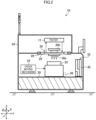
- FIG. 2 is a schematic diagram of the prober 10 and the tester 11. Note that among the XYZ directions perpendicular to each other in the drawing, the XY directions are horizontal directions, and the Z direction is an up-down direction. As shown in Figure 2 , roughly, the prober 10 includes a base 20, a load port 21 (see Figure 13 ), a chuck 22, a chuck moving mechanism 24, a card holding unit 26, a card holder 28, the probe card 30, a card conveying mechanism 32, and a housing 34 that houses these.
- the detailed configuration of the probers 10 is a publicly known technology (see, for example, Japanese Patent Application Laid-Open No. 2018-117096 ), only a part of the configuration of the probers 10 is described here.
- the chuck 22 is held movably in each direction of the XYZ directions and is held rotatably in a ⁇ direction that is a rotational direction around an axis parallel to the Z direction.
- the card conveying mechanism 32 is also held movably in the Y direction.
- the load port 21 (see Figure 13 ) is loaded with a cassette CS that houses semiconductor wafers W to be inspected by the OHT 54 of the wafer conveying mechanism 14 described later.
- the prober 10 includes a conveying mechanism that conveys semiconductor wafers W between the load port 21 and the chuck 22.
- the semiconductor wafer W is held by various holding methods such as vacuum suction. Inside the chuck 22, a temperature regulation unit (illustration omitted) is provided for regulating the temperature of the semiconductor wafer W.
- the chuck 22 includes a coupling part 36 at a position facing the card conveying mechanism 32 described later.
- the coupling part 36 is used to couple the chuck 22 and the card conveying mechanism 32.
- the coupling part 36 is housed in the chuck 22 except in replacement of the probe card 30 described later.
- the coupling part 36 protrudes from a side surface of the chuck 22 in the Y direction and is coupled to the card conveying mechanism 32 when replacing the probe card 30. Accordingly, when replacing the probe card 30, the chuck 22 and the card conveying mechanism 32 is movable integrally.
- the chuck 22 and the card conveying mechanism 32 may be made to be integrally movable on the constant basis, without installation of the coupling part 36.
- the chuck moving mechanism 24 is a known actuator including a motor or the like.
- the chuck moving mechanism 24 may move the chuck 22 in the XYZ and ⁇ directions.
- the semiconductor wafer W held on the chuck 22 and probe needles 30a described later may be moved relatively to the XYZ and ⁇ directions.
- the chuck moving mechanism 24 moves the chuck 22 and the card conveying mechanism 32 integrally in the Y direction when replacing the probe card 30.
- a mechanism for moving the card conveying mechanism 32 may be provided separately from the chuck moving mechanism 24.
- the card holding unit 26 (also referred to as a head stage) is provided above the chuck 22 in the Z direction and detachably holds the card holder 28.
- the card holder 28 holds an outer circumference of the probe card 30. Accordingly, the card holding unit 26 detachably holds the probe card 30 through the card holder 28.
- Figure 3 is a top view of the card holder 28.
- Figure 4 is an enlarged view of positioning parts 40 provided on the card holder 28.
- the card holder 28 includes a card holding hole 38 where an outer circumferential part of the probe card 30 is held.
- the card holder 28 also includes the positioning parts 40 provided at an interval, along an opening edge part which forms the card holding hole 38.
- the positioning parts 40 each have a guide surface 40a that guides the probe card 30 to the card holding hole 38.
- the guide surface 40a is an inclined surface, and a lower end part of the guide surface 40 in the Z direction is located on the opening edge part of the card holding hole 38.
- the inclined surface (the guide surface 40a) is inclined so as to be gradually away from the card holding hole 38 in a horizontal direction toward an upper side in the Z direction. This makes it possible to guide the probe card 30 to the card holding hole 38 along the guide surface 40a of each of the positioning parts 40.
- the probe card 30 has the probe needles 30a arranged in accordance with the arrangement of electrode pads of a large number of unillustrated semiconductor chips formed on the semiconductor wafer W or the like.
- a hold part (to-be-held part) 30b is provided on the upper surface of the probe card 30.
- the hold part 30b is held by a lift holding unit 54a (see Figure 1 ) of the OHT 54 provided to the wafer conveying mechanism 14 described later.
- the probe card 30 is further provided with unillustrated connection terminals that are electrically connected to the probe needles 30a, and the tester 11 is connected to the connection terminals.
- the tester 11 supplies various test signals to the electrode pads of the respective semiconductor chips of the semiconductor wafer W through the connection terminals and the probe needles 30a of the probe card 30, and receives and analyzes signals output from the electrode pads to inspect (test) whether or not each of the semiconductor chips operate normally.
- the configuration of the tester 11 and a test method thereof are known technologies, detailed description thereof is omitted.
- the probe card 30 used for such inspection of the semiconductor chips is replaced, for example, depending on the type of the semiconductor chips or replaced for every prescribed number of times of inspection.
- the aforementioned chuck moving mechanism 24, the card conveying mechanism 32 described later, and the wafer conveying mechanism 14 described later are used to automatically replace the probe card 30.
- replacement of the probe card 30 includes a case where a new probe card 30 is mounted on the prober 10 in a state where no probe card 30 is mounted on the prober 10.
- the present embodiment describes about a case where the probe card (prove card to be replaced) 30 which is already held by the card holding unit 26 to be replaced, is replaced with a new probe card 30.
- the card conveying mechanism 32 In a case where the probe card 30 is replaced, the card conveying mechanism 32, together with the chuck moving mechanism 24, performs: separation processing of integrally conveying the card holder 28 and the prove card 30 to be replaced from a "holding position" to a "replacement position”; and mounting processing of integrally conveying the card holder 28 and the new probe card 30 from the "replacement position" to the "holding position".
- the holding position is a position where the card holding unit 26 holds the probe card 30 and the card holder 28.
- the replacement position is a position where the replacement of the probe card 30 is performed in the prober 10, and more specifically, the position where the OHT 54 described later (see Figure 1 ) may withdraw and deliver the probe card 30 (see Figure 8 ).
- the card conveying mechanism 32 integrally conveys the card holder 28 and the probe card 30 between the holding position and the replacement position.
- the card conveying mechanism 32 holds a substantially planar tray 42, which may hold (may support) the probe card 30 and the card holder 28, in such a manner that the tray 42 may be displaced between a laid state parallel to an XZ plane (see Figure 2 ) and an upright state parallel to an XY plane (see Figure 7 ). Further, the card conveying mechanism 32 holds the tray 42 in the upright state in such a manner that the tray 42 may be vertically movable in the Z direction (see Figure 7 ).
- Figure 5 is a perspective view of the tray 42 that holds (supports) the probe card 30 and the card holder 28.
- Figure 6 is a top view of the tray 42.
- the tray 42 has a holder holding hole 44 that holds an outer circumferential part of the card holder 28, and holds the card holder 28 with the holder holding hole 44 in the upright state. This allows the tray 42 to integrally hold the probe card 30 and the card holder 28.
- the tray 42 is equipped with holder sensors 46 that detect presence or absence of the card holder 28, and card sensors 48 that detect presence or absence of the probe card 30.
- Each of the holder sensors 46 is, for example, a pressing type (or pressure sensitive type) sensor provided on the bottom surface of the holder holding hole 44. In a case where the card holder 28 is held in the holder holding hole 44, each of the holder sensors 46 is pressed by the card holder 28 and changes its sensor output value. This makes it possible to detect the presence or absence of the card holder 28 on the tray 42 based on the sensor output value of each of the holder sensors 46.
- Each of the card sensors 48 is, for example, a pressing type sensor provided inside the holder holding hole 44.
- the card sensors 48 respectively have sensor heads. Each of the sensor heads protrudes upward in the Z direction from the inside of the card holding hole 38 in a case where the card holder 28 is held in the holder holding hole 44. Accordingly, in a case the probe card 30 is held in the card holding hole 38, each of the card sensors 48 is pressed by the card holder 28 and changes its sensor output value. This makes it possible to detect the presence or absence of the probe card 30 on the tray 42 based on the sensor output value of each of the card sensors 48.
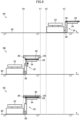
- Figures 7 and 8 are explanatory views for illustrating the separation processing at the time of replacing the probe card 30. Note that in Figures 7 and 8 ( Figures 9 and 10 described later), the internal structure of the prober 10 and the probe card 30 or the like are simply described in order to prevent complicated drawings, and in addition, the size of the probe card 30 and the card holder 28 is emphasized more than the size of the tray 42 so as to clarify that the probe card 30 and the card holder 28 are conveyed on the tray 42.
- the chuck 22 is positioned at an inspection position Y1 that is a position vertically below the card holding unit 26.
- the card conveying mechanism 32 is positioned at the replacement position.
- the tray 42 of the card conveying mechanism 32 is switched to the laid state.
- the chuck moving mechanism 24 moves the chuck 22 to a coupling position Y3.
- the coupling position Y3 is a position adjacent to the replacement position .
- the chuck 22 may be coupled to the card conveying mechanism 32.
- the coupling part 36 protrudes in the Y direction from the side surface of the chuck 22 and is coupled to the card conveying mechanism 32. Accordingly, the chuck 22 and the card conveying mechanism 32 become integrally movable in the Y direction.
- the chuck moving mechanism 24 moves the chuck 22 to a tray switching position Y2 between the inspection position Y1 and the coupling position Y3. After this movement is completed, the card conveying mechanism 32 switches the tray 42 from the laid state to the upright state.
- the chuck moving mechanism 24 moves the chuck 22 to a separation/mounting position Y0.
- the separation/mounting position Y0 is a position where the position of the tray 42 is adjusted to a position vertically below the card holding unit 26. More specifically, the separation/mounting position Y0 is the position where the holder holding hole 44 of the tray 42 matches the card holder 28 held on the card holding unit 26.
- the card conveying mechanism 32 lifts the tray 42 and conveys the tray 42 to a position where the tray 42 is brought into contact with the card holder 28 held by the card holding unit 26. As a result, the card holder 28 is held inside the holder holding hole 44 of the tray 42.
- the probe card 30 is held through the card holder 28.
- the card conveying mechanism 32 lowers the tray 42.
- the chuck moving mechanism 24 moves the chuck 22 to the coupling position Y3. Accordingly, the tray 42 of the card conveying mechanism 32 is conveyed to the replacement position, and so the probe card 30 and the card holder 28 are also conveyed to the replacement position. Note that a door 35 is provided in front of the replacement position, which will be described later in detail.
- the chuck moving mechanism 24 conveys the tray 42 toward the replacement position, the chuck moving mechanism 24 temporarily stops conveyance of the tray 42 in front of the door 35, and restarts conveyance of the tray 42 after the door 35 is opened (see Figure 22 described later).
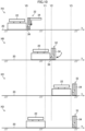
- Figures 9 and 10 are explanatory views for illustrating the mounting processing when replacing the probe card 30.
- the chuck moving mechanism 24 moves the chuck 22 to the separation/mounting position Y0 as shown by reference numeral 9B in Figure 9 . Accordingly, the tray 42, the probe card 30, and the card holder 28 are located (position-adjusted) to a position vertically below the card holding unit 26. Then, the card conveying mechanism 32 lifts the tray 42. As a result, the card holder 28 and the probe card 30 held on the tray 42 are also integrally lifted.
- the card conveying mechanism 32 continuously lifts the tray 42 until the card holder 28 reaches the card holding unit 26 (holding position). Accordingly, the tray 42, the probe card 30, and the card holder 28 are conveyed from the replacement position to the holding position. In a case where this conveyance is completed, the card holding unit 26 holds the card holder 28. As a result, the new probe card 30 is mounted on the card holding unit 26 through the card holder 28.
- the chuck moving mechanism 24 moves the chuck 22 to the tray switching position Y2. After this movement is completed, the card conveying mechanism 32 switches the tray 42 from the upright state to the laid state.
- the chuck moving mechanism 24 moves the chuck 22 to the coupling position Y3. Then, in a case where the coupling part 36 is housed in the chuck 22, the coupling between the chuck 22 and the card conveying mechanism 32 is released. As a result, the card conveying mechanism 32 is arranged at the replacement position before the start of the separation processing.
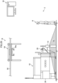
- Figure 11 is a perspective view of the door 35 of the housing 34 switched to an opened state.
- Figure 12 is a perspective view of the door 35 of the housing 34 switched to a closed state.
- the housing 34 has an opening part 34a formed so as to expose the replacement position, and more specifically, the tray 42 or the like that has been moved to the replacement position, to the outside.
- part of the tray 42 or the like that has been moved to the replacement position protrudes to the outside of the housing 34 through the opening part 34a.
- the door 35 is turnably (pivotably) provided so as to be switchable between the opened state where the opening part 34a is opened (see Figure 11 ) and the closed state where the opening part 34a is covered (see Figure 12 ).
- the opening and closing of the door 35 are executed by a door operating mechanism 49 (see Figure 16 ) including a publicly known actuator such as a motor.
- the door operating mechanism 49 switches the door 35 to the opened state before the tray 42 is moved to the replacement position during separation processing.
- the door operating mechanism 49 also switches the door 35 to the closed state after the tray 42 is housed in the housing 34 during mounting processing.
- FIG 13 is an explanatory view of the laser scanner 12.
- the laser scanner 12 which corresponds to the human detection sensor in the present invention, is arranged in the vicinity of the door 35 (opening part 34a) of the prober 10.
- the laser scanner 12 emits and scans infrared laser light, and detects the infrared laser light hit and reflected by a person H, who is an object to be detected, so as to detect the distance to the person H.
- the installation position of the laser scanner 12 and a scanning range of the infrared laser light are adjusted so that it possible to detect the presence or absence of the person H intruding into a protected area PA and a warning area WA which are preset based on the replacement position and the position of the door 35.
- the protected area PA is an area that defines a range where the person H may collide with the door 35 in opening and closing or a hand of the person H may be pinched by the door 35. That is, the protected area PA is a range dangerous for the person H if the person H intrudes into the range during opening and closing operation of the door 35.
- the warning area WA is set outside the protected area PA.
- the warning area WA is an area to warn the person H who may intrude into the protected area. Note that the setting of the warning area WA may be omitted.
- a detection signal output from the laser scanner 12 is input into the prober 10, and is further input into the GEM host 16 described later via the prober 10 and the network 18.
- FIG 14 is a schematic view of the OHT 54 of the wafer conveying mechanism 14.
- the wafer conveying mechanism 14 conveys the cassette CS which houses the semiconductor wafers W, between the probers 10 two-dimensionally arranged in the XY directions and a prescribed storage 50 (see Figure 1 ).
- the wafer conveying mechanism 14 performs, for each of the probers 10, delivery (also referred to as "loading") of the cassette CS housing the semiconductor wafers W to be inspected to the prober 10, and withdrawal (also referred to as "unloading") of the cassette CS housing the inspected semiconductor wafers W from the prober 10.
- the wafer conveying mechanism 14 includes: conveying rails 52; and the OHTs 54 that are overhead hoist transports.
- the conveying rails 52 each extend in the X direction and are arranged side by side in the Y direction on a ceiling in the semiconductor manufacturing process (illustration omitted).
- the conveying rails 52 are provided for each row of the probers 10 arranged in the X direction. More specifically, the conveying rails 52 are provided on the ceiling so that, in each row of the probers 10, the conveying rail 52 crosses the load port 21 of each of the probers 10 in a row, as viewed from above in the Z direction.
- the storage 50 stores the cassettes CS that each house the semiconductor wafers W to be inspected, and also stores various types of probe cards 30 corresponding to the types of semiconductor chips of the semiconductor wafers W. Note that the storage 50 that stores the cassettes CS and the storage 50 that stores the probe cards 30 may be provided at different locations from each other.
- the OHT 54 is provided for each of the conveying rails 52, and travels along the corresponding conveying rail 52. Therefore, the OHTs 54 are movable in the X direction. Accordingly, for each row of the probers 10, the corresponding OHT 54 may move to a position directly above (including a position substantially directly above) the load port 21 of each of the probers 10.
- the OHTs 54 each include the lift holding unit 54a which is vertically movable in the Z direction (up-down direction) and whose position is adjustable in the Y direction.
- the lift holding unit 54a When mounting and withdrawing the cassette CS on and from each of the load ports 21, the lift holding unit 54a releasably holds the cassette CS that houses the semiconductor wafers W.
- the OHT 54 moves to the storage 50. Then, the lift holding unit 54a is lowered and the cassette CS is held with the lift holding unit 54a. Subsequently, after lifting the lift holding unit 54a which is holding the cassette CS, the OHT 54 moves to the position directly above the load port 21 of the prober 10 specified by the GEM host 16 described later. Then, after the OHT 54 lowers the lift holding unit 54a and the cassette CS is loaded on the load port 21, the OHT 54 releases the holding of the cassette CS by the lift holding unit 54a. This makes it possible to convey the cassette CS, that is, the semiconductor wafers W to be inspected, from the storage 50 to each of the load ports 21.
- the OHT 54 moves to the position directly above the load port 21 of the prober 10 from which the cassette CS is to be withdrawn by the OHT 54. Then, the lift holding unit 54a is lowered and the cassette CS loaded on the load port 21 is held by the lift holding unit 54a. Then, after lifting the lift holding unit 54a which is holding the cassette CS, the OHT 54 conveys the cassette CS to the storage 50. Then, after lowering the lift holding unit 54a to the storage 50, the OHT 54 releases the holding of the cassette CS by the lift holding unit 54a. This makes it possible to convey the cassette CS, that is, the inspected semiconductor wafers W, from the load port 21 to the storage 50.
- the wafer conveying mechanism 14 may be used not only for loading and withdrawing the cassette CS, but also for replacing the probe card 30. Specifically, for each of the probers 10, the wafer conveying mechanism 14 performs: withdrawal processing of withdrawing the probe card 30 to be replaced from the tray 42 that is conveyed to the replacement position in the separation processing and conveying the probe card 30 to the storage 50; and delivery processing of delivering a new probe card 30 from the storage 50 to the tray 42 at the replacement position before performing the mounting processing. In this case, in each of the probers 10, the center position of the load port 21 and the replacement position of the tray 42 are adjusted to enable the withdrawal processing and the delivery processing of the probe card 30 by the wafer conveying mechanism 14.
- Figure 15 is an explanatory view for illustrating conditions that enable the withdrawal processing and the delivery processing of the probe card 30 by the wafer conveying mechanism 14.
- description is given with one prober 10 as an example.
- the OHT 54 moves along the conveying rail 52, the OHT 54 is movable in the X direction. While the position of the lift holding unit 54a of the OHT 54 is adjustable in the Y direction, its movable range ⁇ Y is limited (for example, about ten or more mm). Moreover, when each of the probers 10 is installed in the semiconductor manufacturing process, installation errors in the XY directions may occur.
- a center position C1 of the load port 21 and a center position C2 of the tray 42 (holder holding hole 44) set at the replacement position need to be arranged on a substantially the same straight line along the X direction, for each of the probers 10 in the same row.
- the center position C1 and the center position C2 in each of the probers 10 are adjusted and the installation position of each of the probers 10 is adjusted so that the center position C1 of each of the probers 10 is within a Y-directional movable range ⁇ Y of the cassette CS held by the lift holding unit 54a and the center position C2 of each of the probers 10 is within a Y-directional movable range ⁇ Y of the probe card 30 held by the lift holding unit 54a.
- the lift holding unit 54a may load the cassette CS on the load port 21 and load the probe card 30 at the replacement position, within movable ranges of the cassette CS and the probe card 30 in the Y direction.
- the center position C1 and the center position C2 of each of the probers 10 in each row are arranged on a substantially straight line in the X direction, so that the position of the lift holding unit 54a of the OHT 54 may be adjusted to the position directly above the center position C2.
- the OHT 54 may withdraw the probe card 30 to be replaced from the card holder 28 on the tray 42 or may load a new probe card 30 into the card holding hole 38 of the card holder 28 on the tray 42.
- the wafer conveying mechanism 14 may perform the withdrawal processing and the delivery processing of the probe card 30.
- the hold part 30b of the probe card 30 is adjusted so as to have the shape and arrangement that can be held by the lift holding unit 54a.
- the hold part 30b of the probe card 30 may be made in common with a hold part (illustration omitted) of the cassette CS.
- Figure 16 is a functional block diagram of the prober control unit 58 of the prober 10 and the GEM host 16. As shown in Figure 16 , the prober 10 includes the prober control unit 58 in addition to each unit described above.
- the prober control unit 58 comprehensively controls the operation of the prober 10 under the control of the GEM host 16 described later.
- the prober control unit 58 includes an arithmetic circuit having various processors (processors) and memories or the like.
- the various processors include a central processing unit (CPU), a graphics processing unit (GPU), an application specific integrated circuit (ASIC), and a programmable logic device (for example, a simple programmable logic device (SPLD), a complex programmable logic device (CPLD), and a field programmable gate arrays (FPGA)).
- SPLD simple programmable logic device
- CPLD complex programmable logic device
- FPGA field programmable gate arrays
- various functions of the prober control unit 58 may be implemented by one processor, or may be implemented by processors of the same type or the different types.
- the prober control unit 58 is connected to the tester 11, the chuck moving mechanism 24, the card conveying mechanism 32, the holder sensors 46, the card sensors 48, and the door operating mechanism 49. Further, the prober control unit 58 is connected to the laser scanner 12 via an unillustrated connection interface. In addition, the prober control unit 58 is connected to the GEM host 16 via an unillustrated communication interface and the network 18.
- the prober control unit 58 executes a control program read from an unillustrated storage unit to function as a transmission and reception control unit 60, an inspection control unit 62, a separation control unit 64, a mounting control unit 66, a scanner control unit 68, and a door operation control unit 70.
- the transmission and reception control unit 60 exchanges various information with the GEM host 16 via the network 18. For example, the transmission and reception control unit 60 receives a "replacement instruction" of the probe card 30 from the GEM host 16 before the start of the separation processing. After the separation processing is completed, the transmission and reception control unit 60 transmits a "replacement preparation complete notification" to the GEM host 16. After the delivery processing by the OHT 54 is completed, the transmission and reception control unit 60 receives a "start instruction of mounting processing" from the GEM host 16.
- the transmission and reception control unit 60 transmits "read information" on the probe card 30 that is information read from the probe card 30 to GEM host 16 (see Figure 31 ).
- the transmission and reception control unit 60 also receives an "authentication result” of the probe card 30 transmitted from the GEM host 16 in response to the transmission of the "read information".
- the transmission and reception control unit 60 further transmits a "replacement complete notification" of the probe card 30 to the GEM host 16.
- the transmission and reception control unit 60 outputs sensor output values of both the holder sensors 46 and the card sensors 48 to the GEM host 16.
- the output value of each sensor may be constantly output to the GEM host 16.
- the transmission and reception control unit 60 transmits the detection signal output from the laser scanner 12 to the GEM host 16 via the network 18.
- the transmission and reception control unit 60 also exchanges various information (for example, an inspection instruction of the semiconductor wafer W, etc.) with the GEM host 16 at the timing other than the replacement of the probe card 30, detailed description of exchange of these information is omitted here since such exchange is publicly known technology.
- the inspection control unit 62 controls the tester 11 and the chuck moving mechanism 24 under the control of the GEM host 16 to execute: positioning between the semiconductor wafer W held on the chuck 22 and the probe needles 30a; bringing the probe needles 30a in contact with the semiconductor chips of the semiconductor wafer W; and testing with the tester 11.
- the separation control unit 64 controls the chuck moving mechanism 24, the coupling part 36, the card conveying mechanism 32, and the card holding unit 26 to execute the separation processing shown in Figures 7 and 8 described above. After completion of the separation processing, the separation control unit 64 transmits the "replacement preparation complete notification" from the transmission and reception control unit 60 to the GEM host 16 via the network 18.
- the mounting control unit 66 controls the chuck moving mechanism 24, the coupling part 36, the card conveying mechanism 32, and the card holding unit 26 to execute the mounting processing shown in Figures 9 and 10 described above.
- the mounting control unit 66 also reads information on the probe card 30 by a publicly known method in the middle of the mounting processing, and causes the transmission and reception control unit 60 to transmit the "read information" to the GEM host 16 via the network 18. After the mounting processing is completed, the mounting control unit 66 further causes the transmission and reception control unit 60 to transmit the "replacement complete notification" to the GEM host 16 via the network 18.
- the scanner control unit 68 uses the laser scanner 12 to continuously detect the presence or absence of a person H intruding into the protected area PA and the warning area WA. Note that the detection by the laser scanner 12 may be performed at all times.
- the door operation control unit 70 drives the door operating mechanism 49 to switch the door 35 from the closed state to the opened state.
- the door operation control unit 70 drives the door operating mechanism 49 to switch the door 35 from the opened state to the closed state.
- the door operation control unit 70 acquires a detection signal input from the laser scanner 12. Then, in a case where the person H intrudes into the protected area PA, the door operation control unit 70 stops driving of the door operating mechanism 49 based on the detection result of the laser scanner 12. As a result, the opening and closing operation of the door 35 may be stopped before the door 35 collides with the person or the hand (fingers) of the person is pinched.
- the door operation control unit 70 While the person H intrudes into the protected area PA, the door operation control unit 70 continues to stop driving of the door operating mechanism 49. Then, the door operation control unit 70 restarts driving of the door operating mechanism 49 in response to switching from the presence to the absence of the person H intruding into the protected area PA based on the detection result of the laser scanner 12.
- the GEM host 16 comprehensively controls the operation of the probers 10 and the OHTs 54.
- the GEM host 16 includes an arithmetic circuit having various processors and memories or the like. Note that various functions of the GEM host 16 may be implemented by one processor, and may be implemented by processors of the same type or the different types. As long as it is possible to comprehensively control the operation of the probers 10 and the OHTs 54, a control device other than the GEM host 16 may be used.
- the GEM host 16 executes a control program read from the unillustrated storage unit to function as an inspection start control unit 80, a separation processing start control unit 82, a withdrawal control unit 84, a delivery control unit 86, a mounting processing start control unit 88, and an authentication control unit 90.
- the inspection start control unit 80 After the OHT 54 conveys the cassette CS from the storage 50 to the load port 21 of the prober 10, the inspection start control unit 80 outputs an inspection instruction of the semiconductor wafer W to the prober 10 via the network 18.
- the inspection instruction is input into the inspection control unit 62 via the transmission and reception control unit 60. Therefore, the inspection control unit 62 controls the tester 11 and the chuck moving mechanism 24 to execute testing of the semiconductor chips of the semiconductor wafer W.
- the separation processing start control unit 82 outputs a replacement instruction of the probe card 30 to the transmission and reception control unit 60 of the prober 10 via the network 18 at prescribed replacement timing for replacing the probe card 30.
- the replacement instruction is input into the separation control unit 64 and the door operation control unit 70 via the transmission and reception control unit 60.
- the separation control unit 64 controls the chuck moving mechanism 24, the coupling part 36, the card conveying mechanism 32, and the card holding unit 26 to execute the separation processing.
- the separation control unit 64 causes the transmission and reception control unit 60 to transmit the "replacement preparation complete notification" to the GEM host 16.
- the door operation control unit 70 drives the door operating mechanism 49 to switch the door 35 to the opened state in the middle of the separation processing.
- examples of the replacement timing of the probe card 30 may include: timing of switching the type of the semiconductor chips of the semiconductor wafer W to be inspected; a case where the probe card 30 has been used a prescribed number of times or more; and a case where an operator manually inputs the replacement instruction of the probe card 30 into the GEM host 16.
- the withdrawal control unit 84 controls the OHT 54 to start the withdrawal processing. Specifically, the withdrawal control unit 84 sequentially executes: the processing of moving the OHT 54 to the position directly above the replacement position; the processing of lowering the lift holding unit 54a to the replacement position; the processing of holding the probe card 30 by the lift holding unit 54a, the processing of lifting the lift holding unit 54a; and the processing of conveying the probe card 30 to the storage 50 by the OHT 54.
- the delivery control unit 86 controls the OHT 54 to start delivery processing. Specifically, the delivery control unit 86 first executes the processing of conveying the probe card 30 corresponding to the semiconductor wafer W to be inspected from the storage 50 to the position directly above the replacement position by the OHT 54.
- the delivery control unit 86 performs: the processing of lowering the lift holding unit 54a to the replacement position (tray 42); and the processing of releasing the holding of the probe card 30 by the lift holding unit 54a. In this case, the delivery control unit 86 continues the lowering processing until the sensor output values of the card sensors 48 change, that is, until the card sensors 48 are pressed by the probe card 30. The delivery control unit 86 performs the processing of releasing the holding, in response to the change in sensor output values. Next, the delivery control unit 86 executes the processing of lifting the lift holding unit 54a.
- the mounting processing start control unit 88 outputs a start instruction of the mounting processing of the probe card 30 to the prober 10.
- the start instruction is input into the mounting control unit 66 and the door operation control unit 70 via the transmission and reception control unit 60.
- the mounting control unit 66 controls the chuck moving mechanism 24, the coupling part 36, the card conveying mechanism 32, and the card holding unit 26 to execute the mounting processing, and also causes the transmission and reception control unit 60 to transmit the "read information" and the "replacement complete notification" to the GEM host 16.
- the door operation control unit 70 drives the door operating mechanism 49 to switch the door 35 to the closed state in the middle of the mounting processing.
- FIG 17 is a flowchart showing the flow of the replacement processing of the probe cards 30 of the probers 10 performed in the above wafer test system 2 (corresponding to the method for replacing a probe card in the present invention).
- a separation processing step S1, corresponding to the separation step
- a withdrawal processing step S2, corresponding to the withdrawal step
- a delivery processing step S3, corresponding to the delivery step
- a mounting processing step S4, corresponding to the mounting processing
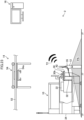
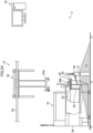
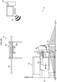
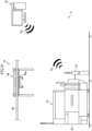
- FIGs 18 to 23 are explanatory views for illustrating the separation processing in step S1 shown in Figure 17 .
- the separation processing start control unit 82 outputs a replacement instruction T1 of the probe card 30 to the corresponding prober 10 via the network 18.
- the replacement instruction T1 is input into the separation control unit 64 and the door operation control unit 70 via the transmission and reception control unit 60 of the prober 10.
- the separation control unit 64 that has received the replacement instruction T1 controls the chuck moving mechanism 24, the coupling part 36, the card conveying mechanism 32, and the card holding unit 26 to start the separation processing. Accordingly, as shown in Figures 7 and 8 described above, the probe card 30 and the card holder 28 at the holding position are held on the tray 42, and then the chuck moving mechanism 24 conveys the tray 42 to the position in front of the door 35.
- the door operation control unit 70 that has received the replacement instruction T1 drives the door operating mechanism 49 to switch the door 35 from the closed state to the opened state.
- the scanner control unit 68 starts detection by the laser scanner 12, that is, detection of the presence or absence of the person H intruding into the protected area PA.
- the detection result of the laser scanner 12 is continuously input into the door operation control unit 70 and is also continuously input into the GEM host 16 from the transmission and reception control unit 60 via the network 18.
- the door operation control unit 70 stops driving of the door operating mechanism 49 based on the detection result of the laser scanner 12. This prevents the door 35 from colliding with the person H. Then, as shown in Figure 22 , in a case where the presence of the person H intruding into the protected area PA is switched to the absence of the person H, based on the detection result of the laser scanner 12, the door operation control unit 70 restarts driving of the door operating mechanism 49. This can reduce the time and efforts of the operator who performs restart operation.
- the separation control unit 64 transmits the replacement preparation complete notification T2 from the transmission and reception control unit 60 to the GEM host 16 via the network 18. This completes the separation processing in step S1.
- the transmission and reception control unit 60 continuously outputs the sensor output values of the card sensors 48 and the like to the GEM host 16 via the network 18.
- the withdrawal control unit 84 stops driving of the OHT 54, and more particularly stops lifting and lowering of the lift holding unit 54a. This prevents the lift holding unit 54a from colliding with the person H. Then, in a case where the presence of the person H intruding into the protected area PA is changed to the absence of the person H, based on the detection result of the laser scanner 12, the withdrawal control unit 84 restarts the driving of the OHT 54. This can reduce the time and efforts of the operator who performs restart operation. This completes the withdrawal processing in step S2.
- FIGs 26 to 28 are explanatory views for illustrating the delivery processing in step S3 shown in Figure 17 .
- the delivery control unit 86 of the GEM host 16 controls the OHT 54 to move the OHT 54 to the storage 50. Then, the delivery control unit 86 causes the lift holding unit 54a to hold a new probe card 30 corresponding to the semiconductor wafer W to be inspected, and controls the OHT 54 to move the position directly above the replacement position.
- the delivery control unit 86 lowers the lift holding unit 54a which is holding the probe card 30. At this time, based on the sensor output values of the respective card sensors 48 input via the network 18, the delivery control unit 86 continues the lowering processing of the lift holding unit 54a until the sensor output values change, that is, until the respective card sensors 48 are pressed by the probe card 30.
- the card holder 28 on the tray 42 is provided with the positioning parts 40 (see Figures 3 and 4 ) around the card holding hole 38.
- the guide surface 40a of each of the positioning parts 40 guides the probe card 30 into the card holding hole 38, so that the probe card 30 is held in the card holder 28.
- the delivery control unit 86 determines that the card holder 28 (tray 42) is switched from absence of the probe card 30 held thereon to presence of the probe card 30 held thereon. Then, the delivery control unit 86 stops the lowering processing of the lift holding unit 54a and releases the holding of the probe card 30 (hold part 30b) by the lift holding unit 54a. As a result, the new probe card 30 is conveyed from the storage 50 to the replacement position. Then, as shown in Figure 28 , the delivery control unit 86 lifts the lift holding unit 54a.
- the delivery control unit 86 stops driving of the OHT 54 as in the case of the withdrawal processing described above.
- the delivery control unit 86 restarts the driving of the OHT 54 in response to the person H leaving the protected area PA. This prevents the lift holding unit 54a from colliding with the person H. This completes the delivery processing in step S3.
- FIGs 29 to 34 are explanatory views for illustrating the mounting processing in step S4 shown in Figure 17 .
- the mounting processing start control unit 88 outputs a mounting instruction T3 of the probe card 30 to the prober 10 via the network 18.
- the mounting instruction T3 is input into the mounting control unit 66 and the door operation control unit 70 via the transmission and reception control unit 60 of the prober 10.
- the mounting control unit 66 which has received the mounting instruction T3, controls the chuck moving mechanism 24, the coupling part 36, the card conveying mechanism 32, and the card holding unit 26 to start the mounting processing. Accordingly, as shown in Figure 9 described above, the chuck moving mechanism 24 and the card conveying mechanism 32 convey the tray 42 toward the holding position.
- the door operation control unit 70 which has received the mounting instruction T3, drives the door operating mechanism 49 to switch the door 35 from the opened state to the closed state.
- the door operation control unit 70 stops driving of the door operating mechanism 49. This prevents the door 35 from colliding with the person H, or prevents the hand or fingers of the person H from being pinched.
- the mounting control unit 66 reads the information on the probe card 30 held in the card holder 28 on the tray 42, and causes the transmission and reception control unit 60 to transmit the read information T4 to the authentication control unit 90 of the GEM host 16 via the network 18.
- the authentication control unit 90 then authenticates the probe card 30 based on the read information T4 input via the network 18, and transmits the authentication result T5 to the mounting control unit 66 via the network 18 and the transmission and reception control unit 60.
- the mounting control unit 66 that has received the authentication result T5 continues the mounting processing in a case where the authentication result T5 is correct, and stops the mounting processing in a case where the authentication result T5 is incorrect.
- the scanner control unit 68 ends the detection with the laser scanner 12.
- the chuck moving mechanism 24 and the card conveying mechanism 32 convey the tray 42 to the holding position as shown in Figure 9 described above, and then the card holding unit 26 holds the card holder 28. This completes the conveyance of the probe card 30 to the holding position, and the new probe card 30 is mounted on the card holding unit 26.
- the chuck moving mechanism 24 moves the chuck 22 to the inspection position Y1 through processes including: lowering of the tray 42 by the card conveying mechanism 32; movement of the chuck 22 by the chuck moving mechanism 24; switching of the tray 42 to the laid state by the card conveying mechanism 32; and release of the coupling between the chuck 22 and the card conveying mechanism 32, as shown in Figure 10 described above.
- the mounting control unit 66 transmits the replacement complete notification from the transmission and reception control unit 60 to the GEM host 16 via the network 18. This completes the mounting processing in step S4.
- the OHTs 54 of the wafer conveying mechanism 14 that load and withdraw the cassettes CS (semiconductor wafers W) of the probers 10 are used in the semiconductor manufacturing process to deliver and withdraw the probe cards 30 of the probers 10. Therefore, it is not necessary to provide a new facility for withdrawal and delivery of the probe cards 30 in the semiconductor manufacturing process. As a result, it is possible to automate the replacement of the probe cards 30 at a low cost while reducing an increase in the installation space in the semiconductor manufacturing process.
- step S1 the separation processing shifts from the state shown by reference numeral 7C of Figure 7 to the state shown by reference numeral 8C of Figure 8 .
- step S2 the withdrawal processing
- step S3 the delivery processing
- step S4 the mounting processing
- the wafer test system 2 includes the probers 10.
- the number of the probers 10 may be one.
- warning in a case where the person H intrudes into the protected area PA, the opening and closing of the door 35 and the driving of the OHTs 54 are stopped based on the detection result of the laser scanner 12.
- warning warning sound, warning indication, etc.
- warning may be issued to the person H at the time when, for example, the intrusion of the person H into the warning area WA occurs.
- the laser scanner 12 is used to detect the presence or absence of the person H intruding into the protected area PA and the warning area WA.
- the presence or absence of the person H intruding into the protected area PA or the like may be detected using, for example, image analysis of images taken by a surveillance camera, or a variety of publicly known human detection sensors.
- OHTs 54 as an example of the wafer conveying mechanism 14
- a variety of publicly known wafer conveying mechanisms may be used, such as an automated guided vehicle (AGV), and an overhead shuttle (OHS) capable of conveying the cassette CS (or only semiconductor wafer W).
- AGV automated guided vehicle
- OHS overhead shuttle
Landscapes
- Engineering & Computer Science (AREA)
- Physics & Mathematics (AREA)
- General Physics & Mathematics (AREA)
- General Engineering & Computer Science (AREA)
- Computer Hardware Design (AREA)
- Microelectronics & Electronic Packaging (AREA)
- Environmental & Geological Engineering (AREA)
- Testing Or Measuring Of Semiconductors Or The Like (AREA)
- Container, Conveyance, Adherence, Positioning, Of Wafer (AREA)
Abstract
Description
- The present invention relates to a wafer test system that inspects semiconductor wafers using a prober, a probe card replacing method for replacing the probe card of the prober, and the prober used for the wafer test system.
- On a surface of a semiconductor wafer, semiconductor chips having identical electric element circuits are formed. Electrical characteristics of each semiconductor chip are inspected by a wafer test system before semiconductor chips are individually cut by a dicer in a semiconductor manufacturing process. The wafer test system includes a prober and a tester (see Patent Literature 1).
- In the prober, a probe card having probe needles is moved relatively to a wafer chuck while a semiconductor wafer is held on the wafer chuck, so as to bring each probe needle into electrical contact (contact) with an electrode pad of each semiconductor chip. The tester supplies various test signals to each semiconductor chip via a terminal connected to each probe needle, and receives and analyzes signals output from each semiconductor chip to test whether or not each semiconductor chip operates normally.
- In recent years, automation of the semiconductor manufacturing process has progressed, and automation of the wafer test systems has also progressed. For example, in a wafer test system described in
Patent Literature 1, a cassette housing semiconductor wafers to be inspected therein, is loaded on a load port of a prober by an overhead hoist transport (OHT). Then, the wafer test system sets a semiconductor wafer on a wafer chuck, brings each probe needle into contact with each semiconductor chip on the semiconductor wafer, and tests each semiconductor chip with a tester. The cassette housing inspected semiconductor wafers is then withdrawn from the prober by the OHT. Thus, semiconductor wafers may be inspected without involvement of an operator. - Patent Literature 1:
Japanese Patent Application Laid-Open No. 2007-329458 - Incidentally, the types of semiconductor chips formed on semiconductor wafers are diverse, and the types of probe cards used to inspect the semiconductor chips are also diverse. Therefore, in wafer test systems, there may be a case where the type of the probe card set in a prober need to be replaced depending on the type of semiconductor chips to be inspected. In the past, an operator always involved in the replacement of the probe card in the prober, and the replacement was performed manually or semi-automatically. For this reason, apparatuses delivered to the United States and Europe are required to meet prescribed safety standards (e.g. SEMI standard S2CE). For example, when a door of a prober is opened and closed at the time of replacement of a probe card, it is necessary to turn off a power of driving units of the prober. Furthermore, since the probe card may be accidentally dropped at the time of manual replacement of the probe card by an operator, there is a strong demand for automatic replacement of the probe card in the prober in the semiconductor manufacturing process.
- In order to automate the replacement of the probe card in the prober, it is necessary to automate withdrawal of a probe card from the prober to be replaced to a new probe card and delivery of the new probe card to the prober. However, there are problems of increase in cost and installation space, when facilities for withdrawing and delivering probe cards are newly provided in the semiconductor manufacturing process.
- The present invention has been made in view of such circumstances, and aims to provide a wafer test system, a method for replacing a probe card, and a prober, capable of automating replacement of probe cards at a low cost while suppressing increase of installation space.
- A wafer test system for accomplishing the object of the present invention includes: a prober which includes a chuck for holding a semiconductor wafer and a probe card having probe needles thereon, and brings the probe needles in contact with semiconductor chips formed on the semiconductor wafer to inspect the semiconductor chips; an overhead hoist transport which is movable along a conveying rail while holding a cassette that houses semiconductor wafers, and configured to deliver the cassette that houses semiconductor wafers to be inspected to the prober and withdraw the cassette that houses semiconductor wafers that have been inspected from the prober; a conveying control unit configured to control the overhead hoist transport to convey the probe card between a replacement position of the probe card predetermined in the prober and a storage of the probe card located in a place different from the prober; a card conveying mechanism which is provided to the prober, and configured to convey the probe card between a holding position where the probe card is held within the prober and the replacement position; a separation control unit configured to control the card conveying mechanism to execute separation processing of conveying the probe card to be replaced from the holding position to the replacement position; and a mounting control unit configured to control the card conveying mechanism to execute mounting processing of conveying a new probe card from the replacement position to the holding position.
- The wafer test system makes it possible to perform automatic replacement of the probe card of the prober using the overhead hoist transport for cassette conveyance.
- In the wafer test system according to another aspect of the present invention, the prober includes a housing configured to house the chuck, the probe card, and the card conveying mechanism; an opening part formed on the housing to expose the replacement position to outside of the housing; a door switchable between an opened state where the opening part is opened and a closed state where the opening part is covered; a door operating mechanism configured to switch the door between the opened state and the closed state; and a door operation control unit configured to drive the door operating mechanism to switch the door from the closed state to the opened state in the separation processing, and drive the door operating mechanism to switch the door from the opened state to the closed state in the mounting processing.
- The wafer test system according to another aspect of the present invention includes a human detection sensor configured to detect presence or absence of a person intruding into a protected area that is preset based on a position of the door, wherein the door operation control unit stops driving of the door operating mechanism while a person is intruding into the protected area based on a detection result by the human detection sensor. This prevents the door from colliding with a person or prevents the hands or the fingers of the person from being pinched by the door.
- In the wafer test system according to another aspect of the present invention, in a case where driving of the door operating mechanism is stopped halfway, the door operation control unit restarts driving of the door operating mechanism in response to change of the detection result by the human detection sensor from the presence to the absence of a person intruding into the protected area. This can reduce the time and efforts of the operator who performs restart operation.
- The wafer test system according to another aspect of the present invention includes a card holding unit configured to detachably hold the probe card at the holding position, in which: the card conveying mechanism includes a tray capable of holding the probe card, and is configured to convey the tray between the holding position and the replacement position; the separation control unit sequentially executes, as the separation processing, processing of driving the card conveying mechanism to convey the tray to the holding position, processing of releasing holding of the probe card by the card holding unit to cause the tray to hold the probe card, and processing of driving the card conveying mechanism to convey the tray from the holding position to the replacement position; and in a case where the new probe card is held on the tray at the replacement position, the mounting control unit sequentially executes, as the mounting processing, processing of driving the card conveying mechanism to convey the tray from the replacement position to the holding position, and processing of causing the card holding unit to hold the probe card. As a result, the separation processing and the mounting processing can also be automated, so that the entire replacement of the probe card of the prober can be performed automatically.
- In the wafer test system according to another aspect of the present invention, the prober includes a card holder that holds the probe card, and the card conveying mechanism integrally conveys the probe card and the card holder between the holding position and the replacement position.
- In the wafer test system according to another aspect of the present invention, the card holder includes a card holding hole that holds the probe card; the overhead hoist transport loads the probe card in the card holding hole of the card holder at the replacement position; the wafer test system comprises a plurality of positioning parts provided at an opening edge part which forms the card holding hole of the card holder; and each of the plurality of positioning parts has a guide surface configured to guide the probe card to the card holding hole in a case where the overhead hoist transport loads the probe card in the card holding hole.
- In the wafer test system according to another aspect of the present invention, the conveying control unit controls the overhead hoist transport to execute withdrawal processing of conveying the probe card to be replaced of the prober from the replacement position to the storage, and delivery processing of conveying the new probe card from the storage to the replacement position; the wafer test system comprises a human detection sensor configured to detect presence or absence of a person intruding into a protected area that is preset based on the replacement position; the conveying control unit stops the withdrawal processing during a state of the presence of a person intruding into the protected area, based on a detection result by the human detection sensor; and the conveying control unit stops the delivery processing during the state of the presence of the person intruding into the protected area, based on the detection result by the human detection sensor. This prevents the overhead hoist transport from colliding with the person.
- In the wafer test system according to another aspect of the present invention, the conveying control unit controls the overhead hoist transport to execute withdrawal processing of conveying the probe card to be replaced of the prober from the replacement position to the storage, and delivery processing of conveying the new probe card from the storage to the replacement position; the overhead hoist transport includes a lift holding unit configured to be vertically movable and detachably hold the cassette or the probe card; the conveying control unit executes, as the withdrawal processing, processing of moving the overhead hoist transport to a position directly above the replacement position, processing of lowering the lift holding unit to the replacement position, processing of causing the lift holding unit to hold the probe card at the replacement position, processing of lifting the lift holding unit, and processing of moving the overhead hoist transport from the position directly above the replacement position to the storage; and the conveying control unit executes, as the delivery processing, processing of causing the lift holding unit to hold the probe card in the storage, processing of moving the overhead hoist transport from the storage to the position directly above the replacement position, processing of lowering the lift holding unit, processing of causing the lift holding unit to release holding of the probe card at the replacement position, and processing of lifting the lift holding unit. This makes it possible to perform automatic replacement of the probe card of the prober using the overhead hoist transport for cassette conveyance.
- The wafer test system according to another aspect of the present invention includes a card conveying mechanism provided in the prober and configured to convey the probe card between the holding position where the probe card is held within the prober and the replacement position, wherein: the card conveying mechanism includes a tray capable of holding the probe card, and configured to convey the tray between the holding position and the replacement position; the wafer test system comprises a card sensor provided in the tray and configured to detect presence or absence of the probe card on the tray; and the conveying control unit executes processing of lowering the lift holding unit while the card sensor detects the absence of the probe card on the tray, and further executes processing of releasing holding of the probe card by the lift holding unit and lifting the lift holding unit in response to a detection result by the card sensor switching from the absence to the presence of the probe card on the tray. This makes it possible to automate the delivery processing.
- In the wafer test system according to another aspect of the present invention, the conveying rail extends in an X direction out of XYZ directions perpendicular to each other; the overhead hoist transport includes a lift holding unit which is vertically movable in the Z direction and whose position is adjustable within a predetermined movable range in the Y direction, the lift holding unit configured to be capable of detachably holding the cassette or the probe card; the prober includes a load port which is provided at a position different from the replacement position in the X direction and configured to be loaded with the cassette by the overhead hoist transport; and within the movable range of the lift holding unit in the Y direction, the lift holding unit is capable of loading the cassette on the load port and capable of loading the probe card at the replacement position. This makes it possible to withdraw the probe card from the replacement position and to deliver the probe card to the replacement position using the overhead hoist transport for cassette conveyance.
- A probe card replacing method for accomplishing the object of the present invention is a method for replacing a probe card for a prober which includes a chuck for holding a semiconductor wafer and a probe card having probe needles thereon, and brings the probe needles in contact with semiconductor chips formed on the semiconductor wafer to inspect the semiconductor chips, the probe card replacing method including: a separation step in which a card conveying mechanism of the prober executes separation processing of conveying the probe card to be replaced from a holding position where the probe card is held inside the prober to a replacement position of the probe card that is predetermined in the prober; a withdrawal step in which an overhead hoist transport executes withdrawal processing of conveying the probe card to be replaced that has been conveyed to the replacement position, from the replacement position to a storage of the probe card located in a place different from the prober, wherein the overhead hoist transport is configured to move along a conveying rail while holding a cassette that houses semiconductor wafers and configured to deliver the cassette that houses semiconductor wafers to be inspected to the prober and withdraw the cassette that houses semiconductor wafers that have been inspected, from the prober; a delivery step in which the overhead hoist transport executes delivery processing of conveying a new probe card from the storage to the replacement position; and a mounting step in which the card conveying mechanism executes mounting processing of conveying the new probe card from the replacement position to the holding position.
- A prober for accomplishing the object of the present invention is a prober which includes a chuck for holding a semiconductor wafer and a probe card having probe needles thereon, and brings the probe needles in contact with semiconductor chips formed on the semiconductor wafer to inspect the semiconductor chips, the prober including: a card conveying mechanism configured to convey the probe card between a holding position in the prober and a replacement position where the probe card is replaced; and a load port configured to be loaded with a cassette that houses semiconductor wafers by an overhead hoist transport that is movable along a conveying rail extending in an X direction out of XYZ directions perpendicular to each other and includes a lift holding unit which is vertically movable in the Z direction and whose position is adjustable within a predetermined movable range in the Y direction, wherein: within the movable range of the lift holding unit in the Y direction, the lift holding unit is capable of loading the cassette on the load port and capable of loading the probe card at the replacement position; the probe card includes a hold part that is held by the lift holding unit; and the replacement position is a position where the probe card is replaceable by the overhead hoist transport.
- The present invention may automate the replacement of a probe card at a low cost while suppressing an increase in installation space.
-
-
Figure 1 is a schematic diagram of a wafer test system. -
Figure 2 is a schematic diagram of a prober and a tester. -
Figure 3 is a top view of a card holder. -
Figure 4 is an enlarged view of positioning parts provided on a card holder. -
Figure 5 is a perspective view of a tray that holds the probe card and the card holder. -
Figure 6 is a top view of the tray. -
Figure 7 is an explanatory view for illustrating separation processing when replacing the probe card. -
Figure 8 is an explanatory view for illustrating the separation processing when replacing the probe card. -
Figure 9 is an explanatory view for illustrating mounting processing when replacing the probe card. -
Figure 10 is an explanatory view for illustrating the mounting processing when replacing the probe card. -
Figure 11 is a perspective view of a door of a housing switched to an opened state. -
Figure 12 is a perspective view of the door of the housing switched to a closed state. -
Figure 13 is an explanatory view of a laser scanner. -
Figure 14 is a schematic view of an OHT of a wafer conveying mechanism. -
Figure 15 is an explanatory view for illustrating conditions for enabling withdrawal processing and delivery processing of the probe card by the wafer conveying mechanism. -
Figure 16 is a functional block diagram of a prober control unit of the prober and a GEM host. -
Figure 17 is a flowchart showing the flow of replacement processing of the probe card of the prober performed in the wafer test system. -
Figure 18 is an explanatory view for illustrating separation processing (replacement instruction) in step S1 shown inFigure 17 . -
Figure 19 is an explanatory view for illustrating the separation processing (tray conveyance) in step S1 shown inFigure 17 . -
Figure 20 is an explanatory view for illustrating the separation processing (start of switching to a door opened state) in step S1 shown inFigure 17 . -
Figure 21 is an explanatory view for illustrating the separation processing (emergency stop of a door operating mechanism) in step S1 shown inFigure 17 . -
Figure 22 is an explanatory view for illustrating the separation processing (restart of driving of the door operating mechanism) in step S1 shown inFigure 17 . -
Figure 23 is an explanatory view for illustrating the separation processing (notification of completion of replacement preparation) in step S1 shown inFigure 17 . -
Figure 24 is an explanatory view for illustrating the withdrawal processing (lowering of a lift holding unit) in step S2 shown inFigure 17 . -
Figure 25 is an explanatory view for illustrating the withdrawal processing (lifting of the lift holding unit) in step S2 shown inFigure 17 . -
Figure 26 is an explanatory view for illustrating delivery processing (conveying the probe card) in step S3 shown inFigure 17 . -
Figure 27 is an explanatory view for illustrating the delivery processing (lowering of the lift holding unit) in step S3 shown inFigure 17 . -
Figure 28 is an explanatory view for illustrating the delivery processing (lifting of the lift holding unit) in step S3 shown inFigure 17 . -
Figure 29 is an explanatory view for illustrating mounting processing (mounting instruction) in step S4 shown inFigure 17 . -
Figure 30 is an explanatory view for illustrating the mounting processing (start of switching to a door closed state) in step S4 shown inFigure 17 . -
Figure 31 is an explanatory view for illustrating the mounting processing (read information, authentication result) in step S4 shown inFigure 17 . -
Figure 32 is an explanatory view for illustrating the mounting processing (mounting of the probe card) in step S4 shown inFigure 17 . -
Figure 33 is an explanatory view for illustrating the mounting processing (moving a chuck) in step S4 shown inFigure 17 . -
Figure 34 is an explanatory view for illustrating the mounting processing (notification of completion of replacement) in step S4 shown inFigure 17 . -
Figure 1 is a schematic diagram of awafer test system 2. As shown inFigure 1 , thewafer test system 2 automatically inspects the electrical characteristics of each semiconductor chip (illustration omitted) of a semiconductor wafer W using aprober 10 described later. Thewafer test system 2 also automatically performs replacement of aprobe card 30 of theprober 10. - Roughly, the
wafer test system 2 includes theprober 10, a tester 11 (seeFigure 2 ), alaser scanner 12, awafer conveying mechanism 14, and a generic model for communications and control of manufacturing equipment (GEM)host 16 that is a GEM computer. Note that thewafer test system 2 includes two or more probers 10 (seeFigure 14 ). - Each of the
probers 10, thewafer conveying mechanism 14, and theGEM host 16 are connected to each other through a known network (networks) 18. Note that, in actuality, thenetwork 18 that connects each of theprobers 10 and theGEM host 16 is different from thenetwork 18 that connects thewafer conveying mechanism 14 and the GEM host 16 (seeFigure 16 ). Each of theprobers 10 and the wafer conveying mechanism 14 (OHT 54) are connected through an I/O interface 19 (in conformity with SEMI-E48) (SEMI: Semiconductor Equipment and Materials International) (seeFigure 16 ). Thelaser scanner 12, which is connected to theprobers 10, is connected to theGEM host 16 through theprobers 10 and thenetwork 18. -
Figure 2 is a schematic diagram of theprober 10 and thetester 11. Note that among the XYZ directions perpendicular to each other in the drawing, the XY directions are horizontal directions, and the Z direction is an up-down direction. As shown inFigure 2 , roughly, theprober 10 includes abase 20, a load port 21 (seeFigure 13 ), achuck 22, achuck moving mechanism 24, acard holding unit 26, acard holder 28, theprobe card 30, acard conveying mechanism 32, and ahousing 34 that houses these. Here, since the detailed configuration of theprobers 10 is a publicly known technology (see, for example,Japanese Patent Application Laid-Open No. 2018-117096 probers 10 is described here. - On the
base 20, thechuck 22 is held movably in each direction of the XYZ directions and is held rotatably in a θ direction that is a rotational direction around an axis parallel to the Z direction. On thebase 20, thecard conveying mechanism 32 is also held movably in the Y direction. - The load port 21 (see
Figure 13 ) is loaded with a cassette CS that houses semiconductor wafers W to be inspected by theOHT 54 of thewafer conveying mechanism 14 described later. Here, although illustration is omitted, theprober 10 includes a conveying mechanism that conveys semiconductor wafers W between theload port 21 and thechuck 22. - On the upper surface of the
chuck 22, the semiconductor wafer W is held by various holding methods such as vacuum suction. Inside thechuck 22, a temperature regulation unit (illustration omitted) is provided for regulating the temperature of the semiconductor wafer W. - In addition, the
chuck 22 includes acoupling part 36 at a position facing thecard conveying mechanism 32 described later. Thecoupling part 36 is used to couple thechuck 22 and thecard conveying mechanism 32. Thecoupling part 36 is housed in thechuck 22 except in replacement of theprobe card 30 described later. Thecoupling part 36 protrudes from a side surface of thechuck 22 in the Y direction and is coupled to thecard conveying mechanism 32 when replacing theprobe card 30. Accordingly, when replacing theprobe card 30, thechuck 22 and thecard conveying mechanism 32 is movable integrally. Note that, thechuck 22 and thecard conveying mechanism 32 may be made to be integrally movable on the constant basis, without installation of thecoupling part 36. - The
chuck moving mechanism 24 is a known actuator including a motor or the like. Thechuck moving mechanism 24 may move thechuck 22 in the XYZ and θ directions. As a result, the semiconductor wafer W held on thechuck 22 andprobe needles 30a described later may be moved relatively to the XYZ and θ directions. Further, thechuck moving mechanism 24 moves thechuck 22 and thecard conveying mechanism 32 integrally in the Y direction when replacing theprobe card 30. Note that a mechanism for moving thecard conveying mechanism 32 may be provided separately from thechuck moving mechanism 24. - The card holding unit 26 (also referred to as a head stage) is provided above the
chuck 22 in the Z direction and detachably holds thecard holder 28. Thecard holder 28 holds an outer circumference of theprobe card 30. Accordingly, thecard holding unit 26 detachably holds theprobe card 30 through thecard holder 28. -
Figure 3 is a top view of thecard holder 28.Figure 4 is an enlarged view ofpositioning parts 40 provided on thecard holder 28. - As shown in
Figures 3 and4 , thecard holder 28 includes acard holding hole 38 where an outer circumferential part of theprobe card 30 is held. Thecard holder 28 also includes thepositioning parts 40 provided at an interval, along an opening edge part which forms thecard holding hole 38. - In the case of loading the
probe card 30 in thecard holding hole 38 by theOHT 54 described later (seeFigure 27 ), thepositioning parts 40 each have aguide surface 40a that guides theprobe card 30 to thecard holding hole 38. Theguide surface 40a is an inclined surface, and a lower end part of theguide surface 40 in the Z direction is located on the opening edge part of thecard holding hole 38. The inclined surface (theguide surface 40a) is inclined so as to be gradually away from thecard holding hole 38 in a horizontal direction toward an upper side in the Z direction. This makes it possible to guide theprobe card 30 to thecard holding hole 38 along theguide surface 40a of each of thepositioning parts 40. - Back to
Figure 2 , theprobe card 30 has the probe needles 30a arranged in accordance with the arrangement of electrode pads of a large number of unillustrated semiconductor chips formed on the semiconductor wafer W or the like. On the upper surface of theprobe card 30, a hold part (to-be-held part) 30b is provided. Thehold part 30b is held by alift holding unit 54a (seeFigure 1 ) of theOHT 54 provided to thewafer conveying mechanism 14 described later. Theprobe card 30 is further provided with unillustrated connection terminals that are electrically connected to the probe needles 30a, and thetester 11 is connected to the connection terminals. - The
tester 11 supplies various test signals to the electrode pads of the respective semiconductor chips of the semiconductor wafer W through the connection terminals and the probe needles 30a of theprobe card 30, and receives and analyzes signals output from the electrode pads to inspect (test) whether or not each of the semiconductor chips operate normally. Here, since the configuration of thetester 11 and a test method thereof are known technologies, detailed description thereof is omitted. - The
probe card 30 used for such inspection of the semiconductor chips is replaced, for example, depending on the type of the semiconductor chips or replaced for every prescribed number of times of inspection. In thewafer test system 2 according to the present embodiment, the aforementionedchuck moving mechanism 24, thecard conveying mechanism 32 described later, and thewafer conveying mechanism 14 described later are used to automatically replace theprobe card 30. Here, "replacement of theprobe card 30" includes a case where anew probe card 30 is mounted on theprober 10 in a state where noprobe card 30 is mounted on theprober 10. However, as an example, the present embodiment describes about a case where the probe card (prove card to be replaced) 30 which is already held by thecard holding unit 26 to be replaced, is replaced with anew probe card 30. - In a case where the
probe card 30 is replaced, thecard conveying mechanism 32, together with thechuck moving mechanism 24, performs: separation processing of integrally conveying thecard holder 28 and the provecard 30 to be replaced from a "holding position" to a "replacement position"; and mounting processing of integrally conveying thecard holder 28 and thenew probe card 30 from the "replacement position" to the "holding position". Here, the holding position is a position where thecard holding unit 26 holds theprobe card 30 and thecard holder 28. The replacement position is a position where the replacement of theprobe card 30 is performed in theprober 10, and more specifically, the position where theOHT 54 described later (seeFigure 1 ) may withdraw and deliver the probe card 30 (seeFigure 8 ). - In a case where the
card conveying mechanism 32 is coupled to thechuck 22 via thecoupling part 36 when replacing the probe card 30 (seeFigure 7 ), thecard conveying mechanism 32 integrally conveys thecard holder 28 and theprobe card 30 between the holding position and the replacement position. - The
card conveying mechanism 32 holds a substantiallyplanar tray 42, which may hold (may support) theprobe card 30 and thecard holder 28, in such a manner that thetray 42 may be displaced between a laid state parallel to an XZ plane (seeFigure 2 ) and an upright state parallel to an XY plane (seeFigure 7 ). Further, thecard conveying mechanism 32 holds thetray 42 in the upright state in such a manner that thetray 42 may be vertically movable in the Z direction (seeFigure 7 ). -
Figure 5 is a perspective view of thetray 42 that holds (supports) theprobe card 30 and thecard holder 28.Figure 6 is a top view of thetray 42. As shown inFigures 5 and6 , thetray 42 has aholder holding hole 44 that holds an outer circumferential part of thecard holder 28, and holds thecard holder 28 with theholder holding hole 44 in the upright state. This allows thetray 42 to integrally hold theprobe card 30 and thecard holder 28. - The
tray 42 is equipped withholder sensors 46 that detect presence or absence of thecard holder 28, andcard sensors 48 that detect presence or absence of theprobe card 30. Each of theholder sensors 46 is, for example, a pressing type (or pressure sensitive type) sensor provided on the bottom surface of theholder holding hole 44. In a case where thecard holder 28 is held in theholder holding hole 44, each of theholder sensors 46 is pressed by thecard holder 28 and changes its sensor output value. This makes it possible to detect the presence or absence of thecard holder 28 on thetray 42 based on the sensor output value of each of theholder sensors 46. - Each of the
card sensors 48 is, for example, a pressing type sensor provided inside theholder holding hole 44. Thecard sensors 48 respectively have sensor heads. Each of the sensor heads protrudes upward in the Z direction from the inside of thecard holding hole 38 in a case where thecard holder 28 is held in theholder holding hole 44. Accordingly, in a case theprobe card 30 is held in thecard holding hole 38, each of thecard sensors 48 is pressed by thecard holder 28 and changes its sensor output value. This makes it possible to detect the presence or absence of theprobe card 30 on thetray 42 based on the sensor output value of each of thecard sensors 48. -
Figures 7 and8 are explanatory views for illustrating the separation processing at the time of replacing theprobe card 30. Note that inFigures 7 and8 (Figures 9 and10 described later), the internal structure of theprober 10 and theprobe card 30 or the like are simply described in order to prevent complicated drawings, and in addition, the size of theprobe card 30 and thecard holder 28 is emphasized more than the size of thetray 42 so as to clarify that theprobe card 30 and thecard holder 28 are conveyed on thetray 42. - As shown by
reference numeral 7A inFigure 7 , before the start of separation processing, thechuck 22 is positioned at an inspection position Y1 that is a position vertically below thecard holding unit 26. In addition, thecard conveying mechanism 32 is positioned at the replacement position. Moreover, thetray 42 of thecard conveying mechanism 32 is switched to the laid state. - As shown by
reference numeral 7B inFigure 7 , When the separation processing is started, thechuck moving mechanism 24 moves thechuck 22 to a coupling position Y3. The coupling position Y3 is a position adjacent to the replacement position . At the coupling position Y3, thechuck 22 may be coupled to thecard conveying mechanism 32. Then, thecoupling part 36 protrudes in the Y direction from the side surface of thechuck 22 and is coupled to thecard conveying mechanism 32. Accordingly, thechuck 22 and thecard conveying mechanism 32 become integrally movable in the Y direction. - As shown by
reference numeral 7C inFigure 7 , After coupling of thechuck 22 and thecard conveying mechanism 32, thechuck moving mechanism 24 moves thechuck 22 to a tray switching position Y2 between the inspection position Y1 and the coupling position Y3. After this movement is completed, thecard conveying mechanism 32 switches thetray 42 from the laid state to the upright state. - As shown by reference numeral 7D in
Figure 7 , after thetray 42 is switched to the upright state, thechuck moving mechanism 24 moves thechuck 22 to a separation/mounting position Y0. The separation/mounting position Y0 is a position where the position of thetray 42 is adjusted to a position vertically below thecard holding unit 26. More specifically, the separation/mounting position Y0 is the position where theholder holding hole 44 of thetray 42 matches thecard holder 28 held on thecard holding unit 26. After this movement is completed, thecard conveying mechanism 32 lifts thetray 42 and conveys thetray 42 to a position where thetray 42 is brought into contact with thecard holder 28 held by thecard holding unit 26. As a result, thecard holder 28 is held inside theholder holding hole 44 of thetray 42. Theprobe card 30 is held through thecard holder 28. - As shown by
reference numeral 8A inFigure 8 , in a case where thetray 42 holds theprobe card 30 and thecard holder 28, and the holding of thecard holder 28 by thecard holding unit 26 is released, the sensor output values of therespective holder sensors 46 and the output values of therespective card sensors 48 change. Thus, theprobe card 30 and thecard holder 28 are put in a state of being held on thetray 42. - As shown by
reference numeral 8B inFigure 8 , in a case where the holding of thecard holder 28 by thecard holding unit 26 is released, thecard conveying mechanism 32 lowers thetray 42. - As shown by
reference numeral 8C inFigure 8 , in a case where the lowering of thetray 42 is completed, thechuck moving mechanism 24 moves thechuck 22 to the coupling position Y3. Accordingly, thetray 42 of thecard conveying mechanism 32 is conveyed to the replacement position, and so theprobe card 30 and thecard holder 28 are also conveyed to the replacement position. Note that adoor 35 is provided in front of the replacement position, which will be described later in detail. When thechuck moving mechanism 24 conveys thetray 42 toward the replacement position, thechuck moving mechanism 24 temporarily stops conveyance of thetray 42 in front of thedoor 35, and restarts conveyance of thetray 42 after thedoor 35 is opened (seeFigure 22 described later). When thetray 42 is conveyed to the replacement position, it becomes possible to perform withdrawal of theprobe card 30 to be replaced from thetray 42 by theOHT 54 described later (seeFigure 25 ) and delivery of thenew probe card 30 to thetray 42 by the OHT 54 (seeFigure 27 ). -
Figures 9 and10 are explanatory views for illustrating the mounting processing when replacing theprobe card 30. - As shown by
reference numeral 9A inFigure 9 , in a state where thenew probe card 30 is held in thecard holder 28 on thetray 42 set at the replacement position, thechuck moving mechanism 24 moves thechuck 22 to the separation/mounting position Y0 as shown byreference numeral 9B inFigure 9 . Accordingly, thetray 42, theprobe card 30, and thecard holder 28 are located (position-adjusted) to a position vertically below thecard holding unit 26. Then, thecard conveying mechanism 32 lifts thetray 42. As a result, thecard holder 28 and theprobe card 30 held on thetray 42 are also integrally lifted. - As shown by
reference numeral 9C inFigure 9 , thecard conveying mechanism 32 continuously lifts thetray 42 until thecard holder 28 reaches the card holding unit 26 (holding position). Accordingly, thetray 42, theprobe card 30, and thecard holder 28 are conveyed from the replacement position to the holding position. In a case where this conveyance is completed, thecard holding unit 26 holds thecard holder 28. As a result, thenew probe card 30 is mounted on thecard holding unit 26 through thecard holder 28. - As shown by reference character XA in
Figure 10 , in a case where thecard holding unit 26 holds thecard holder 28, thecard conveying mechanism 32 lowers thetray 42. As a result, the holding of thecard holder 28 by thetray 42 is released. - As shown by reference character XB in
Figure 10 , in a case where the lowering of thetray 42 is completed, thechuck moving mechanism 24 moves thechuck 22 to the tray switching position Y2. After this movement is completed, thecard conveying mechanism 32 switches thetray 42 from the upright state to the laid state. - As shown by reference character XC in
Figure 10 , after thetray 42 is switched to the laid state, thechuck moving mechanism 24 moves thechuck 22 to the coupling position Y3. Then, in a case where thecoupling part 36 is housed in thechuck 22, the coupling between thechuck 22 and thecard conveying mechanism 32 is released. As a result, thecard conveying mechanism 32 is arranged at the replacement position before the start of the separation processing. - As shown by reference character XD in
Figure 10 , in a case where the coupling between thechuck 22 and thecard conveying mechanism 32 is released, thechuck moving mechanism 24 moves thechuck 22 to the inspection position Y1. This completes the mounting processing. -
Figure 11 is a perspective view of thedoor 35 of thehousing 34 switched to an opened state.Figure 12 is a perspective view of thedoor 35 of thehousing 34 switched to a closed state. As shown inFigures 11 and12 , thehousing 34 has anopening part 34a formed so as to expose the replacement position, and more specifically, thetray 42 or the like that has been moved to the replacement position, to the outside. Here, in the present embodiment, part of thetray 42 or the like that has been moved to the replacement position protrudes to the outside of thehousing 34 through theopening part 34a. - In the
housing 34, thedoor 35 is turnably (pivotably) provided so as to be switchable between the opened state where theopening part 34a is opened (seeFigure 11 ) and the closed state where theopening part 34a is covered (seeFigure 12 ). The opening and closing of thedoor 35 are executed by a door operating mechanism 49 (seeFigure 16 ) including a publicly known actuator such as a motor. Thedoor operating mechanism 49 switches thedoor 35 to the opened state before thetray 42 is moved to the replacement position during separation processing. Thedoor operating mechanism 49 also switches thedoor 35 to the closed state after thetray 42 is housed in thehousing 34 during mounting processing. -
Figure 13 is an explanatory view of thelaser scanner 12. As shown inFigures 13 andFigure 1 described above, thelaser scanner 12, which corresponds to the human detection sensor in the present invention, is arranged in the vicinity of the door 35 (openingpart 34a) of theprober 10. For example, thelaser scanner 12 emits and scans infrared laser light, and detects the infrared laser light hit and reflected by a person H, who is an object to be detected, so as to detect the distance to the person H. The installation position of thelaser scanner 12 and a scanning range of the infrared laser light are adjusted so that it possible to detect the presence or absence of the person H intruding into a protected area PA and a warning area WA which are preset based on the replacement position and the position of thedoor 35. - The protected area PA is an area that defines a range where the person H may collide with the
door 35 in opening and closing or a hand of the person H may be pinched by thedoor 35. That is, the protected area PA is a range dangerous for the person H if the person H intrudes into the range during opening and closing operation of thedoor 35. - The warning area WA is set outside the protected area PA. The warning area WA is an area to warn the person H who may intrude into the protected area. Note that the setting of the warning area WA may be omitted.
- A detection signal output from the
laser scanner 12 is input into theprober 10, and is further input into theGEM host 16 described later via theprober 10 and thenetwork 18. -
Figure 14 is a schematic view of theOHT 54 of thewafer conveying mechanism 14. As shown inFigures 14 andFigure 1 described above, thewafer conveying mechanism 14 conveys the cassette CS which houses the semiconductor wafers W, between theprobers 10 two-dimensionally arranged in the XY directions and a prescribed storage 50 (seeFigure 1 ). Specifically, thewafer conveying mechanism 14 performs, for each of theprobers 10, delivery (also referred to as "loading") of the cassette CS housing the semiconductor wafers W to be inspected to theprober 10, and withdrawal (also referred to as "unloading") of the cassette CS housing the inspected semiconductor wafers W from theprober 10. - The
wafer conveying mechanism 14 includes: conveyingrails 52; and theOHTs 54 that are overhead hoist transports. The conveying rails 52 each extend in the X direction and are arranged side by side in the Y direction on a ceiling in the semiconductor manufacturing process (illustration omitted). In other words, the conveyingrails 52 are provided for each row of theprobers 10 arranged in the X direction. More specifically, the conveyingrails 52 are provided on the ceiling so that, in each row of theprobers 10, the conveyingrail 52 crosses theload port 21 of each of theprobers 10 in a row, as viewed from above in the Z direction. - One end side of the conveying
rails 52 is connected to thestorage 50. Thestorage 50 stores the cassettes CS that each house the semiconductor wafers W to be inspected, and also stores various types ofprobe cards 30 corresponding to the types of semiconductor chips of the semiconductor wafers W. Note that thestorage 50 that stores the cassettes CS and thestorage 50 that stores theprobe cards 30 may be provided at different locations from each other. - The
OHT 54 is provided for each of the conveyingrails 52, and travels along the corresponding conveyingrail 52. Therefore, theOHTs 54 are movable in the X direction. Accordingly, for each row of theprobers 10, the correspondingOHT 54 may move to a position directly above (including a position substantially directly above) theload port 21 of each of theprobers 10. In addition, theOHTs 54 each include thelift holding unit 54a which is vertically movable in the Z direction (up-down direction) and whose position is adjustable in the Y direction. - When mounting and withdrawing the cassette CS on and from each of the
load ports 21, thelift holding unit 54a releasably holds the cassette CS that houses the semiconductor wafers W. - When loading the cassette CS on the
load port 21, theOHT 54 moves to thestorage 50. Then, thelift holding unit 54a is lowered and the cassette CS is held with thelift holding unit 54a. Subsequently, after lifting thelift holding unit 54a which is holding the cassette CS, theOHT 54 moves to the position directly above theload port 21 of theprober 10 specified by theGEM host 16 described later. Then, after theOHT 54 lowers thelift holding unit 54a and the cassette CS is loaded on theload port 21, theOHT 54 releases the holding of the cassette CS by thelift holding unit 54a. This makes it possible to convey the cassette CS, that is, the semiconductor wafers W to be inspected, from thestorage 50 to each of theload ports 21. - When withdrawing the cassette CS from the
load port 21, theOHT 54 moves to the position directly above theload port 21 of theprober 10 from which the cassette CS is to be withdrawn by theOHT 54. Then, thelift holding unit 54a is lowered and the cassette CS loaded on theload port 21 is held by thelift holding unit 54a. Then, after lifting thelift holding unit 54a which is holding the cassette CS, theOHT 54 conveys the cassette CS to thestorage 50. Then, after lowering thelift holding unit 54a to thestorage 50, theOHT 54 releases the holding of the cassette CS by thelift holding unit 54a. This makes it possible to convey the cassette CS, that is, the inspected semiconductor wafers W, from theload port 21 to thestorage 50. - The
wafer conveying mechanism 14 may be used not only for loading and withdrawing the cassette CS, but also for replacing theprobe card 30. Specifically, for each of theprobers 10, thewafer conveying mechanism 14 performs: withdrawal processing of withdrawing theprobe card 30 to be replaced from thetray 42 that is conveyed to the replacement position in the separation processing and conveying theprobe card 30 to thestorage 50; and delivery processing of delivering anew probe card 30 from thestorage 50 to thetray 42 at the replacement position before performing the mounting processing. In this case, in each of theprobers 10, the center position of theload port 21 and the replacement position of thetray 42 are adjusted to enable the withdrawal processing and the delivery processing of theprobe card 30 by thewafer conveying mechanism 14. -
Figure 15 is an explanatory view for illustrating conditions that enable the withdrawal processing and the delivery processing of theprobe card 30 by thewafer conveying mechanism 14. Here, description is given with oneprober 10 as an example. - As described above, because the
OHT 54 moves along the conveyingrail 52, theOHT 54 is movable in the X direction. While the position of thelift holding unit 54a of theOHT 54 is adjustable in the Y direction, its movable range ΔY is limited (for example, about ten or more mm). Moreover, when each of theprobers 10 is installed in the semiconductor manufacturing process, installation errors in the XY directions may occur. Therefore, as shown inFigure 15 , in order to enable the withdrawal processing and the delivery processing of theprobe card 30 by thewafer conveying mechanism 14, a center position C1 of theload port 21 and a center position C2 of the tray 42 (holder holding hole 44) set at the replacement position need to be arranged on a substantially the same straight line along the X direction, for each of theprobers 10 in the same row. - Therefore, in the present embodiment, the center position C1 and the center position C2 in each of the
probers 10 are adjusted and the installation position of each of theprobers 10 is adjusted so that the center position C1 of each of theprobers 10 is within a Y-directional movable range ΔY of the cassette CS held by thelift holding unit 54a and the center position C2 of each of theprobers 10 is within a Y-directional movable range ΔY of theprobe card 30 held by thelift holding unit 54a. Thus, thelift holding unit 54a may load the cassette CS on theload port 21 and load theprobe card 30 at the replacement position, within movable ranges of the cassette CS and theprobe card 30 in the Y direction. Note that as the installation position accuracy of each of theprobers 10, that is, the position accuracy of the center position C1, is higher, a difference A between the center position C1 and the center position C2 can be made larger. Conversely, as the position accuracy of the center position C1 is lower, the difference A needs to be smaller. - In this way, for each row of the
probers 10, the center position C1 and the center position C2 of each of theprobers 10 in each row are arranged on a substantially straight line in the X direction, so that the position of thelift holding unit 54a of theOHT 54 may be adjusted to the position directly above the center position C2. Thus, it becomes possible to lower thelift holding unit 54a and hold thehold part 30b of theprobe card 30 by thelift holding unit 54a. Accordingly, theOHT 54 may withdraw theprobe card 30 to be replaced from thecard holder 28 on thetray 42 or may load anew probe card 30 into thecard holding hole 38 of thecard holder 28 on thetray 42. As a result, it becomes possible for thewafer conveying mechanism 14 to perform the withdrawal processing and the delivery processing of theprobe card 30. - Here, in the present embodiment, in order to hold the
probe card 30 by thelift holding unit 54a of theOHT 54 that is used for replacement (withdrawal and loading) of the cassette CS, thehold part 30b of theprobe card 30 is adjusted so as to have the shape and arrangement that can be held by thelift holding unit 54a. For example, thehold part 30b of theprobe card 30 may be made in common with a hold part (illustration omitted) of the cassette CS. -
Figure 16 is a functional block diagram of theprober control unit 58 of theprober 10 and theGEM host 16. As shown inFigure 16 , theprober 10 includes theprober control unit 58 in addition to each unit described above. - The
prober control unit 58 comprehensively controls the operation of theprober 10 under the control of theGEM host 16 described later. Theprober control unit 58 includes an arithmetic circuit having various processors (processors) and memories or the like. The various processors include a central processing unit (CPU), a graphics processing unit (GPU), an application specific integrated circuit (ASIC), and a programmable logic device (for example, a simple programmable logic device (SPLD), a complex programmable logic device (CPLD), and a field programmable gate arrays (FPGA)). Note that various functions of theprober control unit 58 may be implemented by one processor, or may be implemented by processors of the same type or the different types. - The
prober control unit 58 is connected to thetester 11, thechuck moving mechanism 24, thecard conveying mechanism 32, theholder sensors 46, thecard sensors 48, and thedoor operating mechanism 49. Further, theprober control unit 58 is connected to thelaser scanner 12 via an unillustrated connection interface. In addition, theprober control unit 58 is connected to theGEM host 16 via an unillustrated communication interface and thenetwork 18. - The
prober control unit 58 executes a control program read from an unillustrated storage unit to function as a transmission andreception control unit 60, aninspection control unit 62, aseparation control unit 64, a mountingcontrol unit 66, ascanner control unit 68, and a dooroperation control unit 70. - When replacing the
probe card 30, the transmission andreception control unit 60 exchanges various information with theGEM host 16 via thenetwork 18. For example, the transmission andreception control unit 60 receives a "replacement instruction" of theprobe card 30 from theGEM host 16 before the start of the separation processing. After the separation processing is completed, the transmission andreception control unit 60 transmits a "replacement preparation complete notification" to theGEM host 16. After the delivery processing by theOHT 54 is completed, the transmission andreception control unit 60 receives a "start instruction of mounting processing" from theGEM host 16. - After the
door 35 is switched to the closed state in the middle of the mounting processing, the transmission andreception control unit 60 transmits "read information" on theprobe card 30 that is information read from theprobe card 30 to GEM host 16 (seeFigure 31 ). The transmission andreception control unit 60 also receives an "authentication result" of theprobe card 30 transmitted from theGEM host 16 in response to the transmission of the "read information". After the mounting processing is completed, the transmission andreception control unit 60 further transmits a "replacement complete notification" of theprobe card 30 to theGEM host 16. - Furthermore, during delivery processing of the probe card 30 (during lifting and lowering of the
lift holding unit 54a in particular), the transmission andreception control unit 60 outputs sensor output values of both theholder sensors 46 and thecard sensors 48 to theGEM host 16. The output value of each sensor may be constantly output to theGEM host 16. - Furthermore, while the
laser scanner 12 is in operation, the transmission andreception control unit 60 transmits the detection signal output from thelaser scanner 12 to theGEM host 16 via thenetwork 18. Note that, although the transmission andreception control unit 60 also exchanges various information (for example, an inspection instruction of the semiconductor wafer W, etc.) with theGEM host 16 at the timing other than the replacement of theprobe card 30, detailed description of exchange of these information is omitted here since such exchange is publicly known technology. - The
inspection control unit 62 controls thetester 11 and thechuck moving mechanism 24 under the control of theGEM host 16 to execute: positioning between the semiconductor wafer W held on thechuck 22 and the probe needles 30a; bringing the probe needles 30a in contact with the semiconductor chips of the semiconductor wafer W; and testing with thetester 11. - Under the control of the
GEM host 16, theseparation control unit 64 controls thechuck moving mechanism 24, thecoupling part 36, thecard conveying mechanism 32, and thecard holding unit 26 to execute the separation processing shown inFigures 7 and8 described above. After completion of the separation processing, theseparation control unit 64 transmits the "replacement preparation complete notification" from the transmission andreception control unit 60 to theGEM host 16 via thenetwork 18. - Under the control of the
GEM host 16, the mountingcontrol unit 66 controls thechuck moving mechanism 24, thecoupling part 36, thecard conveying mechanism 32, and thecard holding unit 26 to execute the mounting processing shown inFigures 9 and10 described above. The mountingcontrol unit 66 also reads information on theprobe card 30 by a publicly known method in the middle of the mounting processing, and causes the transmission andreception control unit 60 to transmit the "read information" to theGEM host 16 via thenetwork 18. After the mounting processing is completed, the mountingcontrol unit 66 further causes the transmission andreception control unit 60 to transmit the "replacement complete notification" to theGEM host 16 via thenetwork 18. - During a period from the start of switching the
door 35 to the opened state by thedoor operating mechanism 49 in the middle of the separation processing to the completion of switching thedoor 35 to the closed state by thedoor operating mechanism 49 in the middle of the mounting processing, thescanner control unit 68 uses thelaser scanner 12 to continuously detect the presence or absence of a person H intruding into the protected area PA and the warning area WA. Note that the detection by thelaser scanner 12 may be performed at all times. - In a case where the
tray 42 is conveyed to the position in front of thedoor 35 in the middle of the separation processing, the dooroperation control unit 70 drives thedoor operating mechanism 49 to switch thedoor 35 from the closed state to the opened state. In a case where thetray 42 is housed in thehousing 34 in the middle of the mounting processing, the dooroperation control unit 70 drives thedoor operating mechanism 49 to switch thedoor 35 from the opened state to the closed state. - During such opening and closing operation of the
door 35 by thedoor operating mechanism 49, the dooroperation control unit 70 acquires a detection signal input from thelaser scanner 12. Then, in a case where the person H intrudes into the protected area PA, the dooroperation control unit 70 stops driving of thedoor operating mechanism 49 based on the detection result of thelaser scanner 12. As a result, the opening and closing operation of thedoor 35 may be stopped before thedoor 35 collides with the person or the hand (fingers) of the person is pinched. - While the person H intrudes into the protected area PA, the door
operation control unit 70 continues to stop driving of thedoor operating mechanism 49. Then, the dooroperation control unit 70 restarts driving of thedoor operating mechanism 49 in response to switching from the presence to the absence of the person H intruding into the protected area PA based on the detection result of thelaser scanner 12. - The
GEM host 16 comprehensively controls the operation of theprobers 10 and theOHTs 54. TheGEM host 16 includes an arithmetic circuit having various processors and memories or the like. Note that various functions of theGEM host 16 may be implemented by one processor, and may be implemented by processors of the same type or the different types. As long as it is possible to comprehensively control the operation of theprobers 10 and theOHTs 54, a control device other than theGEM host 16 may be used. - The
GEM host 16 executes a control program read from the unillustrated storage unit to function as an inspectionstart control unit 80, a separation processingstart control unit 82, awithdrawal control unit 84, adelivery control unit 86, a mounting processingstart control unit 88, and anauthentication control unit 90. - After the
OHT 54 conveys the cassette CS from thestorage 50 to theload port 21 of theprober 10, the inspectionstart control unit 80 outputs an inspection instruction of the semiconductor wafer W to theprober 10 via thenetwork 18. The inspection instruction is input into theinspection control unit 62 via the transmission andreception control unit 60. Therefore, theinspection control unit 62 controls thetester 11 and thechuck moving mechanism 24 to execute testing of the semiconductor chips of the semiconductor wafer W. - The separation processing
start control unit 82 outputs a replacement instruction of theprobe card 30 to the transmission andreception control unit 60 of theprober 10 via thenetwork 18 at prescribed replacement timing for replacing theprobe card 30. The replacement instruction is input into theseparation control unit 64 and the dooroperation control unit 70 via the transmission andreception control unit 60. Accordingly, theseparation control unit 64 controls thechuck moving mechanism 24, thecoupling part 36, thecard conveying mechanism 32, and thecard holding unit 26 to execute the separation processing. After the separation processing is completed, theseparation control unit 64 causes the transmission andreception control unit 60 to transmit the "replacement preparation complete notification" to theGEM host 16. Moreover, the dooroperation control unit 70 drives thedoor operating mechanism 49 to switch thedoor 35 to the opened state in the middle of the separation processing. - Here, examples of the replacement timing of the
probe card 30 may include: timing of switching the type of the semiconductor chips of the semiconductor wafer W to be inspected; a case where theprobe card 30 has been used a prescribed number of times or more; and a case where an operator manually inputs the replacement instruction of theprobe card 30 into theGEM host 16. - The
withdrawal control unit 84 and thedelivery control unit 86, which corresponds to the conveying control unit of the present invention, control theOHTs 54 of thewafer conveying mechanism 14 to execute conveyance between the replacement position of theprobe card 30 and thestorage 50. - When receiving the "replacement preparation complete notification" from the transmission and
reception control unit 60 via thenetwork 18, thewithdrawal control unit 84 controls theOHT 54 to start the withdrawal processing. Specifically, thewithdrawal control unit 84 sequentially executes: the processing of moving theOHT 54 to the position directly above the replacement position; the processing of lowering thelift holding unit 54a to the replacement position; the processing of holding theprobe card 30 by thelift holding unit 54a, the processing of lifting thelift holding unit 54a; and the processing of conveying theprobe card 30 to thestorage 50 by theOHT 54. - After the withdrawal processing is completed, the
delivery control unit 86 controls theOHT 54 to start delivery processing. Specifically, thedelivery control unit 86 first executes the processing of conveying theprobe card 30 corresponding to the semiconductor wafer W to be inspected from thestorage 50 to the position directly above the replacement position by theOHT 54. - Next, based on the sensor output values of the
card sensors 48 input from the transmission andreception control unit 60 via thenetwork 18, thedelivery control unit 86 performs: the processing of lowering thelift holding unit 54a to the replacement position (tray 42); and the processing of releasing the holding of theprobe card 30 by thelift holding unit 54a. In this case, thedelivery control unit 86 continues the lowering processing until the sensor output values of thecard sensors 48 change, that is, until thecard sensors 48 are pressed by theprobe card 30. Thedelivery control unit 86 performs the processing of releasing the holding, in response to the change in sensor output values. Next, thedelivery control unit 86 executes the processing of lifting thelift holding unit 54a. - Here, in a case where the state of the presence of the person H intruding into the protected area PA occurs based on the detection signal of the
laser scanner 12 input from the transmission andreception control unit 60 via thenetwork 18, thewithdrawal control unit 84 and thedelivery control unit 86 stop driving of theOHT 54, and more particularly, stop lifting and lowering of thelift holding unit 54a. Then, thewithdrawal control unit 84 and thedelivery control unit 86 stop the driving of theOHT 54 while the state of the presence of the person H intruding into the protected area PA continues, and restart the driving of theOHTs 54 in response to switching from the presence to the absence of the person H intruding into the protected area PA. - After the delivery processing is completed, the mounting processing
start control unit 88 outputs a start instruction of the mounting processing of theprobe card 30 to theprober 10. The start instruction is input into the mountingcontrol unit 66 and the dooroperation control unit 70 via the transmission andreception control unit 60. Accordingly, the mountingcontrol unit 66 controls thechuck moving mechanism 24, thecoupling part 36, thecard conveying mechanism 32, and thecard holding unit 26 to execute the mounting processing, and also causes the transmission andreception control unit 60 to transmit the "read information" and the "replacement complete notification" to theGEM host 16. Moreover, the dooroperation control unit 70 drives thedoor operating mechanism 49 to switch thedoor 35 to the closed state in the middle of the mounting processing. - In a case where the "read information" on the
probe card 30 is input via thenetwork 18 from the transmission andreception control unit 60 during the mounting processing, theauthentication control unit 90 authenticates theprobe card 30 using a publicly known method, and transmits the authentication result to the transmission andreception control unit 60 via thenetwork 18. The authentication result is input into the mountingcontrol unit 66 via the transmission andreception control unit 60. Accordingly, the mountingcontrol unit 66 continues the mounting processing in a case where the authentication result is correct, and stops the mounting processing in a case where authentication result is incorrect. -
Figure 17 is a flowchart showing the flow of the replacement processing of theprobe cards 30 of theprobers 10 performed in the above wafer test system 2 (corresponding to the method for replacing a probe card in the present invention). As shown inFigure 17 , in the case of replacing theprobe cards 30 of theprobers 10, a separation processing (step S1, corresponding to the separation step), a withdrawal processing (step S2, corresponding to the withdrawal step), a delivery processing (step S3, corresponding to the delivery step), and a mounting processing (step S4, corresponding to the mounting processing) are executed in sequence for each of theprobers 10 under the control of theGEM host 16. -
Figures 18 to 23 are explanatory views for illustrating the separation processing in step S1 shown inFigure 17 . As shown inFigure 18 , at prescribed replacement timing of theprobe card 30, the separation processingstart control unit 82 outputs a replacement instruction T1 of theprobe card 30 to the correspondingprober 10 via thenetwork 18. The replacement instruction T1 is input into theseparation control unit 64 and the dooroperation control unit 70 via the transmission andreception control unit 60 of theprober 10. - As shown in
Figure 19 , theseparation control unit 64 that has received the replacement instruction T1 controls thechuck moving mechanism 24, thecoupling part 36, thecard conveying mechanism 32, and thecard holding unit 26 to start the separation processing. Accordingly, as shown inFigures 7 and8 described above, theprobe card 30 and thecard holder 28 at the holding position are held on thetray 42, and then thechuck moving mechanism 24 conveys thetray 42 to the position in front of thedoor 35. - Meanwhile, as shown in
Figure 20 , when thechuck moving mechanism 24 conveys thetray 42 to the position in front of thedoor 35, the dooroperation control unit 70 that has received the replacement instruction T1 drives thedoor operating mechanism 49 to switch thedoor 35 from the closed state to the opened state. In response to the start of switching, thescanner control unit 68 starts detection by thelaser scanner 12, that is, detection of the presence or absence of the person H intruding into the protected area PA. The detection result of thelaser scanner 12 is continuously input into the dooroperation control unit 70 and is also continuously input into theGEM host 16 from the transmission andreception control unit 60 via thenetwork 18. - As shown in
Figure 21 , while the person H intrudes into the protected area PA, the dooroperation control unit 70 stops driving of thedoor operating mechanism 49 based on the detection result of thelaser scanner 12. This prevents thedoor 35 from colliding with the person H. Then, as shown inFigure 22 , in a case where the presence of the person H intruding into the protected area PA is switched to the absence of the person H, based on the detection result of thelaser scanner 12, the dooroperation control unit 70 restarts driving of thedoor operating mechanism 49. This can reduce the time and efforts of the operator who performs restart operation. - As shown in
Figure 23 , when thedoor 35 is switched to the opened state, the conveyance of thetray 42 by thechuck moving mechanism 24 is restarted, so that thechuck moving mechanism 24 conveys thetray 42 to the replacement position. As a result, theprobe card 30 held by thecard holder 28 on thetray 42 is also conveyed. After the conveyance is completed, theseparation control unit 64 transmits the replacement preparation complete notification T2 from the transmission andreception control unit 60 to theGEM host 16 via thenetwork 18. This completes the separation processing in step S1. Here, after the separation processing is completed, the transmission andreception control unit 60 continuously outputs the sensor output values of thecard sensors 48 and the like to theGEM host 16 via thenetwork 18. -
Figures 24 to 25 are explanatory views for illustrating the withdrawal processing in step S2 shown inFigure 17 . As shown inFigure 24 , when the replacement preparation complete notification T2 is input via thenetwork 18, thewithdrawal control unit 84 of theGEM host 16 controls theOHT 54 of thewafer conveying mechanism 14 to sequentially execute: processing of moving theOHT 54 to the position directly above the replacement position of theprober 10; processing of lowering thelift holding unit 54a to the replacement position; and processing of holding thehold part 30b of theprobe card 30 by thelift holding unit 54a. Then, as shown inFigure 25 , thewithdrawal control unit 84 controls theOHT 54 to sequentially execute: processing of lifting thelift holding unit 54a which is holding theprobe card 30; and processing of conveying theprobe card 30 to thestorage 50 by theOHT 54. - Here, in a case where the person H intrudes into the protected area PA, based on the detection result of the
laser scanner 12 input from the transmission andreception control unit 60 via thenetwork 18 during execution of each processing described above, thewithdrawal control unit 84 stops driving of theOHT 54, and more particularly stops lifting and lowering of thelift holding unit 54a. This prevents thelift holding unit 54a from colliding with the person H. Then, in a case where the presence of the person H intruding into the protected area PA is changed to the absence of the person H, based on the detection result of thelaser scanner 12, thewithdrawal control unit 84 restarts the driving of theOHT 54. This can reduce the time and efforts of the operator who performs restart operation. This completes the withdrawal processing in step S2. -
Figures 26 to 28 are explanatory views for illustrating the delivery processing in step S3 shown inFigure 17 . As shown inFigure 26 , when the withdrawal processing is completed, thedelivery control unit 86 of theGEM host 16 controls theOHT 54 to move theOHT 54 to thestorage 50. Then, thedelivery control unit 86 causes thelift holding unit 54a to hold anew probe card 30 corresponding to the semiconductor wafer W to be inspected, and controls theOHT 54 to move the position directly above the replacement position. - Then, as shown in
Figure 27 , thedelivery control unit 86 lowers thelift holding unit 54a which is holding theprobe card 30. At this time, based on the sensor output values of therespective card sensors 48 input via thenetwork 18, thedelivery control unit 86 continues the lowering processing of thelift holding unit 54a until the sensor output values change, that is, until therespective card sensors 48 are pressed by theprobe card 30. Here, as described above, thecard holder 28 on thetray 42 is provided with the positioning parts 40 (seeFigures 3 and4 ) around thecard holding hole 38. Accordingly, even when the position of thelift holding unit 54a are displaced in the XY directions (for example, about ± 2 mm), theguide surface 40a of each of thepositioning parts 40 guides theprobe card 30 into thecard holding hole 38, so that theprobe card 30 is held in thecard holder 28. - When the
probe card 30 is held in thecard holder 28, the sensor output values of therespective card sensors 48 change as described above. Thus, thedelivery control unit 86 determines that the card holder 28 (tray 42) is switched from absence of theprobe card 30 held thereon to presence of theprobe card 30 held thereon. Then, thedelivery control unit 86 stops the lowering processing of thelift holding unit 54a and releases the holding of the probe card 30 (hold part 30b) by thelift holding unit 54a. As a result, thenew probe card 30 is conveyed from thestorage 50 to the replacement position. Then, as shown inFigure 28 , thedelivery control unit 86 lifts thelift holding unit 54a. - Here, while the person H intrudes into the protected area PA, based on the detection result of the
laser scanner 12 input from the transmission andreception control unit 60 via thenetwork 18 during delivery processing, thedelivery control unit 86 stops driving of theOHT 54 as in the case of the withdrawal processing described above. Thedelivery control unit 86 restarts the driving of theOHT 54 in response to the person H leaving the protected area PA. This prevents thelift holding unit 54a from colliding with the person H. This completes the delivery processing in step S3. -
Figures 29 to 34 are explanatory views for illustrating the mounting processing in step S4 shown inFigure 17 . As shown inFigure 29 , when the delivery processing is completed, the mounting processingstart control unit 88 outputs a mounting instruction T3 of theprobe card 30 to theprober 10 via thenetwork 18. The mounting instruction T3 is input into the mountingcontrol unit 66 and the dooroperation control unit 70 via the transmission andreception control unit 60 of theprober 10. - Then, the mounting
control unit 66, which has received the mounting instruction T3, controls thechuck moving mechanism 24, thecoupling part 36, thecard conveying mechanism 32, and thecard holding unit 26 to start the mounting processing. Accordingly, as shown inFigure 9 described above, thechuck moving mechanism 24 and thecard conveying mechanism 32 convey thetray 42 toward the holding position. - Meanwhile, as shown in
Figure 30 , when thetray 42, which is conveyed to the holding position, is housed in thehousing 34, the dooroperation control unit 70, which has received the mounting instruction T3, drives thedoor operating mechanism 49 to switch thedoor 35 from the opened state to the closed state. In this case, while the person H intrudes into the protected area PA, based on the detection result of thelaser scanner 12, the dooroperation control unit 70 stops driving of thedoor operating mechanism 49. This prevents thedoor 35 from colliding with the person H, or prevents the hand or fingers of the person H from being pinched. - As shown in
Figure 31 , after (or before) thedoor 35 is switched to the closed state, the mountingcontrol unit 66 reads the information on theprobe card 30 held in thecard holder 28 on thetray 42, and causes the transmission andreception control unit 60 to transmit the read information T4 to theauthentication control unit 90 of theGEM host 16 via thenetwork 18. Theauthentication control unit 90 then authenticates theprobe card 30 based on the read information T4 input via thenetwork 18, and transmits the authentication result T5 to the mountingcontrol unit 66 via thenetwork 18 and the transmission andreception control unit 60. The mountingcontrol unit 66 that has received the authentication result T5 continues the mounting processing in a case where the authentication result T5 is correct, and stops the mounting processing in a case where the authentication result T5 is incorrect. - Moreover when the authentication of the
probe card 30 is completed, thescanner control unit 68 ends the detection with thelaser scanner 12. - As shown in
Figure 32 , when the mounting processing continues, thechuck moving mechanism 24 and thecard conveying mechanism 32 convey thetray 42 to the holding position as shown inFigure 9 described above, and then thecard holding unit 26 holds thecard holder 28. This completes the conveyance of theprobe card 30 to the holding position, and thenew probe card 30 is mounted on thecard holding unit 26. - As shown in
Figure 33 , when mounting of thenew probe card 30 on thecard holding unit 26 is completed, thechuck moving mechanism 24 moves thechuck 22 to the inspection position Y1 through processes including: lowering of thetray 42 by thecard conveying mechanism 32; movement of thechuck 22 by thechuck moving mechanism 24; switching of thetray 42 to the laid state by thecard conveying mechanism 32; and release of the coupling between thechuck 22 and thecard conveying mechanism 32, as shown inFigure 10 described above. - As shown in
Figure 34 , when the movement of thechuck 22 to the inspection position Y1 is completed, the mountingcontrol unit 66 transmits the replacement complete notification from the transmission andreception control unit 60 to theGEM host 16 via thenetwork 18. This completes the mounting processing in step S4. - Thus, according to the present embodiment, the
OHTs 54 of thewafer conveying mechanism 14 that load and withdraw the cassettes CS (semiconductor wafers W) of theprobers 10 are used in the semiconductor manufacturing process to deliver and withdraw theprobe cards 30 of theprobers 10. Therefore, it is not necessary to provide a new facility for withdrawal and delivery of theprobe cards 30 in the semiconductor manufacturing process. As a result, it is possible to automate the replacement of theprobe cards 30 at a low cost while reducing an increase in the installation space in the semiconductor manufacturing process. - The embodiment has been described using, as an example, a case where the separation processing is started in a state where the
card holder 28 and theprobe card 30 are held on thecard holding unit 26. However, there may be a case where the separation processing is started in a state where thecard holder 28 and theprobe card 30 are not held on thecard holding unit 26. In this case, in the separation processing (step S1), the processing shifts from the state shown byreference numeral 7C ofFigure 7 to the state shown byreference numeral 8C ofFigure 8 . Then, the withdrawal processing (step S2) is omitted, and the delivery processing (step S3) and the mounting processing (step S4) are executed in sequence. - In the embodiment, the
wafer test system 2 includes theprobers 10. However, the number of theprobers 10 may be one. - In the embodiment, in a case where the person H intrudes into the protected area PA, the opening and closing of the
door 35 and the driving of theOHTs 54 are stopped based on the detection result of thelaser scanner 12. However, warning (warning sound, warning indication, etc.) may be issued to the person H at the time when, for example, the intrusion of the person H into the warning area WA occurs. - In the embodiment, the
laser scanner 12 is used to detect the presence or absence of the person H intruding into the protected area PA and the warning area WA. However, the presence or absence of the person H intruding into the protected area PA or the like may be detected using, for example, image analysis of images taken by a surveillance camera, or a variety of publicly known human detection sensors. - Although the embodiment has been described by taking the
OHTs 54 as an example of thewafer conveying mechanism 14, a variety of publicly known wafer conveying mechanisms may be used, such as an automated guided vehicle (AGV), and an overhead shuttle (OHS) capable of conveying the cassette CS (or only semiconductor wafer W). - In the embodiment, the
probe card 30 is conveyed between thestorage 50 and the replacement position using thewafer conveying mechanism 14 for loading and withdrawing the cassettes CS (semiconductor wafers W). However, theprobe card 30 may be conveyed between thestorage 50 and the replacement position using a conveying mechanism installed separately from thewafer conveying mechanism 14. -
- 2
- Wafer test system
- 10
- Prober
- 11
- Tester
- 12
- Laser scanner
- 14
- Wafer conveying mechanism
- 16
- GEM host
- 18
- Network
- 20
- Base
- 21
- Load port
- 22
- Chuck
- 24
- Chuck moving mechanism
- 26
- Card holding unit
- 28
- Card holder
- 30
- Probe card
- 30a
- Probe needle
- 30b
- Hold part
- 32
- Card conveying mechanism
- 34
- Housing
- 34a
- Opening part
- 35
- Door
- 36
- Coupling part
- 38
- Card holding hole
- 40
- Positioning part
- 40a
- Guide surface
- 42
- Tray
- 44
- Holder holding hole
- 46
- Holder sensor
- 48
- Card sensor
- 49
- Door operating mechanism
- 50
- Storage
- 52
- Conveying rail
- 54a
- Lift holding unit
- 58
- Prober control unit
- 60
- Transmission and reception control unit
- 62
- Inspection control unit
- 64
- Separation control unit
- 66
- Mounting control unit
- 68
- Scanner control unit
- 70
- Door operation control unit
- 80
- Inspection start control unit
- 82
- Separation processing start control unit
- 84
- Withdrawal control unit
- 86
- Delivery control unit
- 88
- Mounting processing start control unit
- 90
- Authentication control unit
- A
- Difference
- C1
- Center position
- C2
- Center position
- CS
- Cassette
- H
- Person
- PA
- Protected area
- T1
- Replacement instruction
- T2
- Replacement preparation complete notification
- T3
- Mounting instruction
- T4
- Read information
- T5
- Authentication result
- W
- Semiconductor wafer
- WA
- Warning area
- Y0
- Mounting position
- Y1
- Inspection position
- Y2
- Tray switching position
- Y3
- Coupling position
- ΔY
- Movable range
Claims (13)
- A wafer test system, comprising:a prober which includes a chuck for holding a semiconductor wafer and a probe card having probe needles thereon, and brings the probe needles in contact with semiconductor chips formed on the semiconductor wafer to inspect the semiconductor chips;an overhead hoist transport which is movable along a conveying rail while holding a cassette that houses semiconductor wafers, and configured to deliver the cassette that houses semiconductor wafers to be inspected to the prober and withdraw the cassette that houses semiconductor wafers that have been inspected from the prober;a conveying control unit configured to control the overhead hoist transport to convey the probe card between a replacement position of the probe card predetermined in the prober and a storage of the probe card located in a place different from the prober;a card conveying mechanism which is provided to the prober, and configured to convey the probe card between a holding position where the probe card is held within the prober and the replacement position;a separation control unit configured to control the card conveying mechanism to execute separation processing of conveying the probe card to be replaced from the holding position to the replacement position; anda mounting control unit configured to control the card conveying mechanism to execute mounting processing of conveying a new probe card from the replacement position to the holding position.
- The wafer test system according to claim 1, wherein
the prober includes:a housing configured to house the chuck, the probe card, and the card conveying mechanism;an opening part formed on the housing to expose the replacement position to outside of the housing;a door switchable between an opened state where the opening part is opened and a closed state where the opening part is covered;a door operating mechanism configured to switch the door between the opened state and the closed state; anda door operation control unit configured to drive the door operating mechanism to switch the door from the closed state to the opened state in the separation processing, and drive the door operating mechanism to switch the door from the opened state to the closed state in the mounting processing. - The wafer test system according to claim 2, comprisinga human detection sensor configured to detect presence or absence of a person intruding into a protected area that is preset based on a position of the door, whereinthe door operation control unit stops driving of the door operating mechanism while a person is intruding into the protected area based on a detection result by the human detection sensor.
- The wafer test system according to claim 3, wherein
in a case where driving of the door operating mechanism is stopped halfway, the door operation control unit restarts driving of the door operating mechanism in response to change of the detection result by the human detection sensor from the presence to the absence of a person intruding into the protected area. - The wafer test system according to any one of claims 1 to 4, comprising
a card holding unit configured to detachably hold the probe card at the holding position, wherein:the card conveying mechanism includes a tray capable of holding the probe card, and is configured to convey the tray between the holding position and the replacement position;the separation control unit sequentially executes, as the separation processing, processing of driving the card conveying mechanism to convey the tray to the holding position, processing of releasing holding of the probe card by the card holding unit to cause the tray to hold the probe card, and processing of driving the card conveying mechanism to convey the tray from the holding position to the replacement position; andin a case where the new probe card is held on the tray at the replacement position, the mounting control unit sequentially executes, as the mounting processing, processing of driving the card conveying mechanism to convey the tray from the replacement position to the holding position, and processing of causing the card holding unit to hold the probe card. - The wafer test system according to any one of claims 1 to 5, whereinthe prober includes a card holder that holds the probe card, andthe card conveying mechanism integrally conveys the probe card and the card holder between the holding position and the replacement position.
- The wafer test system according to claim 6, wherein:the card holder includes a card holding hole that holds the probe card;the overhead hoist transport loads the probe card in the card holding hole of the card holder at the replacement position;the wafer test system comprises a plurality of positioning parts provided at an opening edge part which forms the card holding hole of the card holder; andeach of the plurality of positioning parts has a guide surface configured to guide the probe card to the card holding hole in a case where the overhead hoist transport loads the probe card in the card holding hole.
- The wafer test system according to any one of claims 1 to 7, wherein:the conveying control unit controls the overhead hoist transport to execute withdrawal processing of conveying the probe card to be replaced of the prober from the replacement position to the storage, and delivery processing of conveying the new probe card from the storage to the replacement position;the wafer test system comprises a human detection sensor configured to detect presence or absence of a person intruding into a protected area that is preset based on the replacement position;the conveying control unit stops the withdrawal processing during a state of the presence of a person intruding into the protected area, based on a detection result by the human detection sensor; andthe conveying control unit stops the delivery processing during the state of the presence of the person intruding into the protected area, based on the detection result by the human detection sensor.
- The wafer test system according to any one of claims 1 to 8, wherein:the conveying control unit controls the overhead hoist transport to execute withdrawal processing of conveying the probe card to be replaced of the prober from the replacement position to the storage, and delivery processing of conveying the new probe card from the storage to the replacement position;the overhead hoist transport includes a lift holding unit configured to be vertically movable and detachably hold the cassette or the probe card;the conveying control unit executes, as the withdrawal processing, processing of moving the overhead hoist transport to a position directly above the replacement position, processing of lowering the lift holding unit to the replacement position, processing of causing the lift holding unit to hold the probe card at the replacement position, processing of lifting the lift holding unit, and processing of moving the overhead hoist transport from the position directly above the replacement position to the storage; andthe conveying control unit executes, as the delivery processing, processing of causing the lift holding unit to hold the probe card in the storage, processing of moving the overhead hoist transport from the storage to the position directly above the replacement position, processing of lowering the lift holding unit, processing of causing the lift holding unit to release holding of the probe card at the replacement position, and processing of lifting the lift holding unit.
- The wafer test system according to claim 9, comprising
a card conveying mechanism provided in the prober and configured to convey the probe card between a holding position where the probe card is held within the prober and the replacement position, wherein:the card conveying mechanism includes a tray capable of holding the probe card, and configured to convey the tray between the holding position and the replacement position;the wafer test system comprises a card sensor provided in the tray and configured to detect presence or absence of the probe card on the tray; andthe conveying control unit executes processing of lowering the lift holding unit while the card sensor detects the absence of the probe card on the tray, and further executes processing of releasing holding of the probe card by the lift holding unit and lifting the lift holding unit in response to a detection result by the card sensor switching from the absence to the presence of the probe card on the tray. - The wafer test system according to any one of claims 1 to 10, wherein:the conveying rail extends in an X direction out of XYZ directions perpendicular to each other;the overhead hoist transport includes a lift holding unit which is vertically movable in the Z direction and whose position is adjustable within a predetermined movable range in the Y direction, the lift holding unit configured to be capable of detachably holding the cassette or the probe card;the prober includes a load port which is provided at a position different from the replacement position in the X direction and configured to be loaded with the cassette by the overhead hoist transport; andwithin the movable range of the lift holding unit in the Y direction, the lift holding unit is capable of loading the cassette on the load port and capable of loading the probe card at the replacement position.
- A probe card replacing method for a prober which includes a chuck for holding a semiconductor wafer and a probe card having probe needles thereon, and brings the probe needles in contact with semiconductor chips formed on the semiconductor wafer to inspect the semiconductor chips, the probe card replacing method comprising:a separation step in which a card conveying mechanism of the prober executes separation processing of conveying the probe card to be replaced from a holding position where the probe card is held inside the prober to a replacement position of the probe card that is predetermined in the prober;a withdrawal step in which an overhead hoist transport executes withdrawal processing of conveying the probe card to be replaced that has been conveyed to the replacement position, from the replacement position to a storage of the probe card located in a place different from the prober, wherein the overhead hoist transport is configured to move along a conveying rail while holding a cassette that houses semiconductor wafers and configured to deliver the cassette that houses semiconductor wafers to be inspected to the prober and withdraw the cassette that houses semiconductor wafers that have been inspected, from the prober;a delivery step in which the overhead hoist transport executes delivery processing of conveying a new probe card from the storage to the replacement position; anda mounting step in which the card conveying mechanism executes mounting processing of conveying the new probe card from the replacement position to the holding position.
- A prober which includes a chuck for holding a semiconductor wafer and a probe card having probe needles thereon, and brings the probe needles in contact with semiconductor chips formed on the semiconductor wafer to inspect the semiconductor chips, the prober comprising:a card conveying mechanism configured to convey the probe card between a holding position in the prober and a replacement position where the probe card is replaced; anda load port configured to be loaded with a cassette that houses semiconductor wafers by an overhead hoist transport that is movable along a conveying rail extending in an X direction out of XYZ directions perpendicular to each other and includes a lift holding unit which is vertically movable in the Z direction and whose position is adjustable within a predetermined movable range in the Y direction, wherein:within the movable range of the lift holding unit in the Y direction, the lift holding unit is capable of loading the cassette on the load port and capable of loading the probe card at the replacement position;the probe card includes a hold part that is held by the lift holding unit; andthe replacement position is a position where the probe card is replaceable by the overhead hoist transport.
Applications Claiming Priority (2)
| Application Number | Priority Date | Filing Date | Title |
|---|---|---|---|
| JP2022005019A JP7539624B2 (en) | 2022-01-17 | 2022-01-17 | Wafer Test System and Prober |
| PCT/JP2022/045617 WO2023136009A1 (en) | 2022-01-17 | 2022-12-12 | Wafer test system, method for replacing probe card, and prober |
Publications (2)
| Publication Number | Publication Date |
|---|---|
| EP4468325A1 true EP4468325A1 (en) | 2024-11-27 |
| EP4468325A4 EP4468325A4 (en) | 2025-08-27 |
Family
ID=87278873
Family Applications (1)
| Application Number | Title | Priority Date | Filing Date |
|---|---|---|---|
| EP22920528.1A Pending EP4468325A4 (en) | 2022-01-17 | 2022-12-12 | WAFER TEST SYSTEM, METHOD FOR REPLACING A PROBE CARD, AND PROBE DEVICE |
Country Status (7)
| Country | Link |
|---|---|
| US (1) | US12282061B2 (en) |
| EP (1) | EP4468325A4 (en) |
| JP (3) | JP7539624B2 (en) |
| KR (1) | KR102743153B1 (en) |
| CN (3) | CN121335489A (en) |
| TW (1) | TWI870757B (en) |
| WO (1) | WO2023136009A1 (en) |
Families Citing this family (3)
| Publication number | Priority date | Publication date | Assignee | Title |
|---|---|---|---|---|
| KR102827010B1 (en) * | 2023-09-25 | 2025-06-30 | 주식회사 쎄믹스 | Handling apparatus for Probe card |
| KR102862162B1 (en) * | 2024-01-04 | 2025-09-19 | 주식회사 쎄믹스 | Handling apparatus for Probe card |
| KR102932829B1 (en) * | 2024-01-04 | 2026-03-03 | 주식회사 쎄믹스 | Handling apparatus for Probe card |
Family Cites Families (19)
| Publication number | Priority date | Publication date | Assignee | Title |
|---|---|---|---|---|
| JPH05136219A (en) * | 1991-03-05 | 1993-06-01 | Tokyo Electron Ltd | Inspection equipment |
| JP3193843B2 (en) * | 1995-03-20 | 2001-07-30 | 東京エレクトロン株式会社 | Probe device and probe card replacement method |
| JP2003197711A (en) * | 2001-12-27 | 2003-07-11 | Tokyo Electron Ltd | Object transport system and object transport method |
| JP4134289B2 (en) * | 2002-05-29 | 2008-08-20 | 東京エレクトロン株式会社 | Probe card transport device and adapter |
| JP2007198971A (en) | 2006-01-27 | 2007-08-09 | Advantest Corp | Probe card fixing device, and electronic component testing device provided therewith |
| JP4832151B2 (en) * | 2006-04-25 | 2011-12-07 | 株式会社東京精密 | Probe card delivery method, prober and probe card supply / collection system |
| JP4166813B2 (en) | 2006-05-11 | 2008-10-15 | 東京エレクトロン株式会社 | Inspection apparatus and inspection method |
| TWI452643B (en) * | 2006-05-11 | 2014-09-11 | 東京威力科創股份有限公司 | Inspection device and inspection method |
| JP2008016676A (en) * | 2006-07-06 | 2008-01-24 | Micronics Japan Co Ltd | Probe card automatic exchange mechanism and inspection device |
| WO2008078939A1 (en) * | 2006-12-27 | 2008-07-03 | Secron Co., Ltd. | Probe station, and testing method of wafer using the same |
| JP2013191741A (en) * | 2012-03-14 | 2013-09-26 | Tokyo Electron Ltd | Probe device, and probe card attachment method of probe device |
| JP5894825B2 (en) * | 2012-03-21 | 2016-03-30 | 東京エレクトロン株式会社 | Probe apparatus and wafer transfer unit |
| KR102335827B1 (en) * | 2014-12-24 | 2021-12-08 | 삼성전자주식회사 | apparatus for loading a prove card and system for managing the prove card with the unit |
| KR102338464B1 (en) | 2015-01-08 | 2021-12-15 | 삼성전자주식회사 | Unit for transferring a package and apparatus for managing the package with the unit |
| KR102221110B1 (en) * | 2015-03-13 | 2021-02-26 | 세메스 주식회사 | Carrier unit and system for stocking the same |
| JP2018117096A (en) | 2017-01-20 | 2018-07-26 | 株式会社東京精密 | Prober and method for contacting probe needle |
| JP2018147959A (en) * | 2017-03-02 | 2018-09-20 | 東京エレクトロン株式会社 | Inspection system, and failure analysis/prediction method of inspection system |
| US11099234B2 (en) | 2018-09-18 | 2021-08-24 | Taiwan Semiconductor Manufacturing Co., Ltd. | False detection method for loading probe card |
| KR102158838B1 (en) * | 2019-03-05 | 2020-09-22 | 세메스 주식회사 | Semiconductor manufacturing facility and method of controlling operation of the same |
-
2022
- 2022-01-17 JP JP2022005019A patent/JP7539624B2/en active Active
- 2022-12-12 CN CN202511349667.7A patent/CN121335489A/en active Pending
- 2022-12-12 EP EP22920528.1A patent/EP4468325A4/en active Pending
- 2022-12-12 CN CN202511349678.5A patent/CN121310974A/en active Pending
- 2022-12-12 WO PCT/JP2022/045617 patent/WO2023136009A1/en not_active Ceased
- 2022-12-12 KR KR1020247023595A patent/KR102743153B1/en active Active
- 2022-12-12 CN CN202280089238.9A patent/CN118556283B/en active Active
-
2023
- 2023-01-10 TW TW112100970A patent/TWI870757B/en active
-
2024
- 2024-07-16 US US18/774,727 patent/US12282061B2/en active Active
- 2024-08-09 JP JP2024133861A patent/JP7562938B1/en active Active
- 2024-09-25 JP JP2024165877A patent/JP2024178376A/en active Pending
Also Published As
| Publication number | Publication date |
|---|---|
| WO2023136009A1 (en) | 2023-07-20 |
| CN121310974A (en) | 2026-01-09 |
| US20240369623A1 (en) | 2024-11-07 |
| CN121335489A (en) | 2026-01-13 |
| JP2024155929A (en) | 2024-10-31 |
| JP2023104175A (en) | 2023-07-28 |
| EP4468325A4 (en) | 2025-08-27 |
| TWI870757B (en) | 2025-01-21 |
| US12282061B2 (en) | 2025-04-22 |
| JP7539624B2 (en) | 2024-08-26 |
| KR102743153B1 (en) | 2024-12-17 |
| JP7562938B1 (en) | 2024-10-08 |
| TW202341335A (en) | 2023-10-16 |
| KR20240114781A (en) | 2024-07-24 |
| CN118556283B (en) | 2025-10-03 |
| CN118556283A (en) | 2024-08-27 |
| JP2024178376A (en) | 2024-12-24 |
Similar Documents
| Publication | Publication Date | Title |
|---|---|---|
| EP4468325A1 (en) | Wafer test system, method for replacing probe card, and prober | |
| US4789294A (en) | Wafer handling apparatus and method | |
| US7471077B2 (en) | Conveyor device, electronic device handling apparatus and conveying method in electronic device handling apparatus | |
| US8040140B2 (en) | Method and apparatus for identifying broken pins in a test socket | |
| KR101114617B1 (en) | Monitoring apparatus of neutralization apparatus, monitoring method of neutralization apparatus, and computer readable recording medium having a program for monitoring neutralization apparatus recorded | |
| TWI759545B (en) | Detection system and detection method | |
| JPH06151531A (en) | Prober | |
| TWI763794B (en) | Wafer inspection apparatus and diagnostic method of wafer inspection apparatus | |
| JP5137965B2 (en) | Conveying device and electronic component handling device | |
| US8283940B2 (en) | Probe device, processing device, and probe testing method | |
| JP2547406B2 (en) | Multi-product measuring device | |
| KR101218507B1 (en) | Probe apparatus | |
| KR20080096021A (en) | Test device for semiconductor device manufacturing facility | |
| KR102862162B1 (en) | Handling apparatus for Probe card | |
| KR102932829B1 (en) | Handling apparatus for Probe card | |
| KR101415276B1 (en) | Wafer prober system being capable of inspecting wafer surface | |
| WO1999044231A1 (en) | Semiconductor wafer inspection apparatus | |
| JP2008147202A (en) | Semiconductor inspection apparatus and semiconductor inspection system using the same | |
| CN116802782A (en) | Inspection equipment setting method and inspection equipment | |
| KR20010097278A (en) | Inspection apparatus of semiconductor wafer | |
| JPH04146640A (en) | Handler device |
Legal Events
| Date | Code | Title | Description |
|---|---|---|---|
| STAA | Information on the status of an ep patent application or granted ep patent |
Free format text: STATUS: THE INTERNATIONAL PUBLICATION HAS BEEN MADE |
|
| PUAI | Public reference made under article 153(3) epc to a published international application that has entered the european phase |
Free format text: ORIGINAL CODE: 0009012 |
|
| STAA | Information on the status of an ep patent application or granted ep patent |
Free format text: STATUS: REQUEST FOR EXAMINATION WAS MADE |
|
| 17P | Request for examination filed |
Effective date: 20240716 |
|
| AK | Designated contracting states |
Kind code of ref document: A1 Designated state(s): AL AT BE BG CH CY CZ DE DK EE ES FI FR GB GR HR HU IE IS IT LI LT LU LV MC ME MK MT NL NO PL PT RO RS SE SI SK SM TR |
|
| DAV | Request for validation of the european patent (deleted) | ||
| DAX | Request for extension of the european patent (deleted) | ||
| RIC1 | Information provided on ipc code assigned before grant |
Ipc: H01L 21/677 20060101ALI20250429BHEP Ipc: H01L 21/66 20060101AFI20250429BHEP |
|
| A4 | Supplementary search report drawn up and despatched |
Effective date: 20250728 |
|
| RIC1 | Information provided on ipc code assigned before grant |
Ipc: H01L 21/66 20060101AFI20250722BHEP Ipc: H01L 21/677 20060101ALI20250722BHEP |
|
| STAA | Information on the status of an ep patent application or granted ep patent |
Free format text: STATUS: EXAMINATION IS IN PROGRESS |
|
| 17Q | First examination report despatched |
Effective date: 20260319 |