EP4465273A2 - Stromversorgungsanordnungen für selbsttestende alarmsysteme - Google Patents
Stromversorgungsanordnungen für selbsttestende alarmsysteme Download PDFInfo
- Publication number
- EP4465273A2 EP4465273A2 EP24204694.4A EP24204694A EP4465273A2 EP 4465273 A2 EP4465273 A2 EP 4465273A2 EP 24204694 A EP24204694 A EP 24204694A EP 4465273 A2 EP4465273 A2 EP 4465273A2
- Authority
- EP
- European Patent Office
- Prior art keywords
- self
- alarm system
- test
- power source
- system device
- Prior art date
- Legal status (The legal status is an assumption and is not a legal conclusion. Google has not performed a legal analysis and makes no representation as to the accuracy of the status listed.)
- Pending
Links
Images



Classifications
-
- G—PHYSICS
- G08—SIGNALLING
- G08B—SIGNALLING SYSTEMS, e.g. PERSONAL CALLING SYSTEMS; ORDER TELEGRAPHS; ALARM SYSTEMS
- G08B29/00—Checking or monitoring of signalling or alarm systems; Prevention or correction of operating errors, e.g. preventing unauthorised operation
- G08B29/02—Monitoring continuously signalling or alarm systems
-
- G—PHYSICS
- G08—SIGNALLING
- G08B—SIGNALLING SYSTEMS, e.g. PERSONAL CALLING SYSTEMS; ORDER TELEGRAPHS; ALARM SYSTEMS
- G08B29/00—Checking or monitoring of signalling or alarm systems; Prevention or correction of operating errors, e.g. preventing unauthorised operation
- G08B29/18—Prevention or correction of operating errors
- G08B29/181—Prevention or correction of operating errors due to failing power supply
-
- G—PHYSICS
- G08—SIGNALLING
- G08B—SIGNALLING SYSTEMS, e.g. PERSONAL CALLING SYSTEMS; ORDER TELEGRAPHS; ALARM SYSTEMS
- G08B29/00—Checking or monitoring of signalling or alarm systems; Prevention or correction of operating errors, e.g. preventing unauthorised operation
- G08B29/02—Monitoring continuously signalling or alarm systems
- G08B29/04—Monitoring of the detection circuits
-
- H—ELECTRICITY
- H02—GENERATION; CONVERSION OR DISTRIBUTION OF ELECTRIC POWER
- H02J—ELECTRIC POWER NETWORKS; CIRCUIT ARRANGEMENTS OR SYSTEMS FOR SUPPLYING OR DISTRIBUTING ELECTRIC POWER; SYSTEMS FOR STORING ELECTRIC ENERGY
- H02J7/00—Circuit arrangements for charging or discharging batteries or for supplying loads from batteries
- H02J7/80—Circuit arrangements for charging or discharging batteries or for supplying loads from batteries including monitoring or indicating arrangements
-
- H—ELECTRICITY
- H02—GENERATION; CONVERSION OR DISTRIBUTION OF ELECTRIC POWER
- H02J—ELECTRIC POWER NETWORKS; CIRCUIT ARRANGEMENTS OR SYSTEMS FOR SUPPLYING OR DISTRIBUTING ELECTRIC POWER; SYSTEMS FOR STORING ELECTRIC ENERGY
- H02J9/00—Circuit arrangements for emergency or stand-by power supply, e.g. for emergency lighting
- H02J9/04—Circuit arrangements for emergency or stand-by power supply, e.g. for emergency lighting in which the distribution system is disconnected from the normal source and connected to a standby source
- H02J9/06—Circuit arrangements for emergency or stand-by power supply, e.g. for emergency lighting in which the distribution system is disconnected from the normal source and connected to a standby source with automatic change-over, e.g. UPS systems
-
- H—ELECTRICITY
- H02—GENERATION; CONVERSION OR DISTRIBUTION OF ELECTRIC POWER
- H02J—ELECTRIC POWER NETWORKS; CIRCUIT ARRANGEMENTS OR SYSTEMS FOR SUPPLYING OR DISTRIBUTING ELECTRIC POWER; SYSTEMS FOR STORING ELECTRIC ENERGY
- H02J7/00—Circuit arrangements for charging or discharging batteries or for supplying loads from batteries
Definitions
- the present disclosure relates to devices, systems, and methods for power source arrangements for self-testing alarm systems.
- FIG. 1 An alarm system
- FIG. 1 An alarm system
- FIG. 1 An alarm system
- FIG. 1 An alarm system
- FIG. 1 An alarm system
- FIG. 1 An alarm system
- FIG. 1 An alarm system
- FIG. 1 An alarm system
- FIG. 1 An alarm system
- FIG. 1 An alarm system
- FIG. 1 An alarm system
- FIG. 1 An alarm system
- FIG. 1 An alarm system
- FIG. 1 An alarm system
- FIG. 1 An alarm system
- FIG. 1 An alarm system
- FIG. 1 An alarm system
- FIG. 1 An alarm system
- FIG. 1 An alarm system
- FIG. 1 An alarm system
- FIG. 1 An alarm system
- FIG. 1 An alarm system
- FIG. 1 An alarm system
- FIG. 1 An alarm system
- FIG. 1 An alarm system
- FIG. 1 An alarm system
- FIG. 1 An alarm system
- FIG. 1 An alarm system
- FIG. 1 An alarm system
- FIG. 1 An alarm system
- self-test alarm system devices need to be periodically checked to ensure that they are operating properly.
- Some such devices have mechanisms included within the device that test the function of the self-test alarm system device to make sure it is functioning properly. These mechanisms are referred to as self-test mechanisms and such self-test alarm system devices are referred to as self-test self-test alarm system devices.
- the devices include software/firmware and/or hardware to allow the sensing device to perform a self-test to determine that the self-test alarm system device is operating correctly.
- a self-testing fire alarm system self-test alarm system device can, for example, include a particle generator and an airflow generator configured to generate an aerosol to trigger a fire response by a smoke sensor within the device to determine whether the self-testing fire sensing self-test alarm system device is functioning properly based on the fire response and the determined airflow rate.
- Some self-test components use a large amount of power (e.g., in some instances, in the range of 3-4 Watts) during the self-test process. Since one power source is typically used for all of the components of such self-test alarm system device within an alarm system, the large power draw from all of these devices means that, on wired-loop based fire systems, the self-testing would need to be accomplished on only one device at a time. This means, that it can take significant time to carry out each test, as each individual self-test self-test alarm system device would need to be tested in series.
- power e.g., in some instances, in the range of 3-4 Watts
- the system would need to be placed in test mode for a considerable amount of time (e.g., in the region of one hour for a electrically connected loop having 150 detectors). While the system can be returned to active mode in between tests to check for fire events, it does mean that the facility may not get immediate responses to a real fire, either by a pull station being activated or a detector signaling a hazard event alarm.
- Devices, systems, and methods for power source arrangements for self-testing alarm systems are described herein.
- the embodiments of the present disclosure enhance self-test arrangements for wired alarm systems and can speed up the self-testing process as well as giving more accurate readings on battery capacities, among other benefits.
- it can be important to have an accurate battery measurement as the self-testing process must be able to work reliably over the life of the self-test alarm system device while potentially using a significant amount of power.
- Examples of embodiments of the present disclosure include a self-test alarm system device having a self-testing capability wherein the device includes one of: a self-test module powered by an integrated primary wired power source or battery; or a self-test module powered by an integrated secondary wired power source.
- a self-test alarm system device having a self-testing capability the device includes a first independent power source connected to a detector module and a second independent power source connected to a self-test module.
- the self-test module powered by a local power source or battery would (when placed in self-test mode) enable the detector to draw current from the integrated power source in order to carry out a self-test function.
- This arrangement will also enable all detectors on the loop, with this power source, to be able to simultaneously go into self-test mode on the loop.
- Such an arrangement can, for example, provide self-testing results back to the technician for the whole all self-testing devices on the system in less than one minute. This can be irrespective of the size of site and installation as the power sources are located local by the self-testing self-test alarm system devices.
- a further application for embodiments of the present disclosure is for alarm systems with heavy loading of devices on alarm system loops/spurs or with devices having longer cable lengths. These devices could be used at the extremities of the alarm system, in order to enable the self-test processes to be carried out effectively, for example, on the most challenging applications.
- the self-test module powered, for example, by radio frequency (RF) detectors existing wired power source/battery or a dedicated wired power source/battery, when placed in self-test mode would enable the detector to draw current from the specified power source in order to carry out the self-test function. Further, such embodiments enable all detectors on the RF system with this function to simultaneously go into self-test mode.
- RF radio frequency
- a further application for embodiments of the present disclosure relates to battery load testing.
- this implementation will place the self-test alarm system devices into a load test.
- a load test allows for the opportunity to get a reading on the battery capacity and determine, for example as part of routine maintenance, whether the batteries providing power to a specific self-test alarm system device need replacement. This process can be accomplished, for example, by a controller attached to the self-test alarm system devices.
- a can refer to one or more such things, while “a plurality of” something can refer to more than one such things.
- a number of components can refer to one or more components, while “a plurality of components” can refer to more than one component.
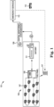
- FIG. 1 is an example of an alarm system having a number of self-testing self-test alarm system devices that can be used in accordance with one or more embodiments of the present disclosure.
- an alarm response system 101 includes a building alarm system 103 within a building 117, a central monitoring station having at least one computing device 109 with links to a number of emergency service providers 113 that can, for example, dispatch emergency personnel 115 (e.g., fire fighters) to the building 117.
- emergency service providers 113 can, for example, dispatch emergency personnel 115 (e.g., fire fighters) to the building 117.
- the emergency personnel can be dispatched, for example, in response to an event alarm signal being generated by the control panel 105 within the alarm system 103.
- An event alarm signal is generated in response to data from one or more alarm system self-test alarm system devices 107 (e.g., self-test alarm system devices, such as smoke detectors) within the alarm system indicating that an event (e.g., a fire) may be occurring.
- alarm system self-test alarm system devices 107 e.g., self-test alarm system devices, such as smoke detectors
- the alarm system can be any system that is used to monitor events that will affect occupants of the building. Examples of suitable alarm system types include fire alarm, building security, and building access systems. As shown in Figure 1 , the alarm system illustrated is a fire alarm system and includes a number of alarm system devices 107 and a control panel for managing the operation of the alarm system and its devices.
- control panel refers to a device to control components of an alarm system of a facility (building).
- control panel 105 can be a fire control panel that can receive information from event devices 107 and determine whether a hazard event is occurring or has occurred.
- the control panel 105 can be connected to the number of alarm system devices 107.
- alarm system device refers to a device that can receive an input relating to an event.
- an event can be, for instance, a hazard event such as a fire.
- an alarm system device can receive an input relating to a fire occurring in the facility.
- Such alarm system devices 107 can be a part of an alarm system of the facility and can include devices such as fire sensors, smoke detectors, heat detectors, carbon monoxide (CO) detectors, other chemical detectors, or combinations of these; interfaces; pull stations; input/output modules; aspirating units; and/or audio/visual devices, such as speakers, sounders, buzzers, microphones, cameras, video displays, video screens, among other types of alarm system devices.
- devices such as fire sensors, smoke detectors, heat detectors, carbon monoxide (CO) detectors, other chemical detectors, or combinations of these
- interfaces such as fire sensors, smoke detectors, heat detectors, carbon monoxide (CO) detectors, other chemical detectors, or combinations of these
- interfaces such as fire sensors, smoke detectors, heat detectors, carbon monoxide (CO) detectors, other chemical detectors, or combinations of these
- interfaces such as fire sensors, smoke detectors, heat detectors, carbon monoxide (CO) detectors, other chemical detectors, or combinations of these
- alarm system self-test alarm system devices 107 can be automatic, self-test devices, such as smoke detectors, heat detectors, CO detectors, and/or others.
- self-test devices can include mechanisms that generate aerosols, heat, carbon monoxide, etc. and sense these items, as appropriate to the type of device being tested, in the device to test the performance of the device. This can, for example, be used to test the self-test alarm system device's thermal, chemical, and/or photo sensing capabilities.
- the alarm system 103 can also include an edge/gateway device 111.
- the gateway device acts as a pass through device for communicating between the alarm system 103 in the building and the central monitoring station 109 and other components of the response personnel status system 101 that are at remote locations (i.e., outside the building).
- a gateway device of an alarm system at a facility reports event alarm signals to one or more central monitoring servers.
- These servers may be on premise (within the facility) or, as shown in the example of Figure 1 , off premise (at a remote location from the alarm system components).
- the event alarm signals are reported to the appropriate central monitoring station that includes administrators that coordinate activities to respond appropriately based on the type of event that is occurring. For example, a fire event would need a fire based response that would likely include alerting a fire station to send trucks and contacting medical personnel, if injuries seem likely. For a security issue, security personnel and/or the police would be contacted.
- the central monitoring servers are connected back to one or more alarm systems on site and/or remote (cloud) servers.
- FIG. 2 is an example of a self-test alarm system device having self-test capabilities in a self-testing alarm system, in accordance with one or more embodiments of the present disclosure.
- the self-testing self-test alarm system devices of an alarm system such as alarm system 103 of Figure 1 have several components that need power from a power source in order for the device to function properly.
- the power source connections have intentionally not been made in Figure 2 to emphasize the parts of such a device and as the several connection arrangements will be discussed in more detail below.
- a self-test alarm system device 207 can have a controller 218, a detector 220, a self-test module 222, and a power source for the self-test alarm system device 224.
- the controller 218 can include a processor and memory or firmware to carry out control functions for the self-test alarm system device.
- memory can have instructions and/or data stored therein, where the executable instructions are executable by the processor to carry out control functions to control the detector 220 and/or the self-test module 222. Discussed below are several power source arrangements for connecting these and other self-test alarm system device components to one or more power sources.
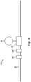
- Figure 3 is an example of a power source arrangement for a self-testing alarm system, in accordance with one or more embodiments of the present disclosure.
- Illustrated in Figure 3 are a number of components within a self-test alarm system device 300 of an alarm system.
- the components include a self-test module 308 electrically connected to a power source 302.
- the power source 302 is connected to the power loop 301 that provides power for the self-test alarm system device.
- the power loop is a wired loop that can be used for distribution of power to components of the self-test alarm system device, such as a detector module or an audio or visual alarm indicator (e.g., strobe or siren).
- the powered loop can also be used as a communication loop.
- a wired power loop having a communications component could be 24V to 48V DC power, with digital communications/data modulated on to it.
- a controller can be used to control the functions of the detector module.
- a controller can also be used to control the functions of the self-test module.
- a single controller can control the functions of the detector and self-test module.
- a charger can be used to extract power from the power loop and distribute it to the power source 302. This can allow the power source to be charged over time as the self-test module uses the power in the power source.
- the power source can be a battery or a capacitor (e.g., a super capacitor).
- the embodiment illustrated in Figure 3 includes a first independent power source (not shown) connected to a detector module (not shown) and a second independent power source 302 connected to a self-test module 308. In this manner, power can be independently provided to the detector module and the self-test module, by different power sources.
- the second independent power source 302 can be directly electrically connected to the power loop 301. In this manner, the second independent power source can receive consistent power over a long period of time without interruption.
- the second independent power source 302 can be directly electrically connected to the self-test module 308.
- the second independent power source can also be directly electrically connected to the power loop in addition to its direct connection to the self-test module.
- the second independent power source 302 receives a trickle charge from the power loop. The trickle charge keeps the second independent power source charged, but does not overly reduce power available at the power loop as it trickles lower power to the second independent power source over a long period of time.
- the self-test alarm system device can include a controller directly electrically connected to a power loop.
- the controller can, for example, be powered by the power loop and can control the flow of power to and from components such as the charger, the power source, and the self-test module.
- the self-test alarm system device can include a charger directly electrically connected to a power loop.
- the charger can also or alternatively be directly electrically connected to the second independent power source. Such embodiments allow the charger to transfer power from the power loop to the self-test module.
- the second power source (connected to the self-test module) can be used to operate the self-test module while the detector module is being powered by the first power source (e.g., power, capacitor, or primary battery).
- the first power source e.g., power, capacitor, or primary battery.
- FIG. 4 is another example of a power source arrangement for a self-testing alarm system, in accordance with one or more embodiments of the present disclosure.
- the components of the self-test alarm system device 400 include a self-test module 408 electrically connected to an independent power source 412.
- the independent power source 412 is electrically connected to the controller 404 which is directly electrically connected to power loop 401 for the self-test alarm system device.
- the power source 412 does not receive any power from the power loop 401.
- the power loop 401 does provide power to the controller 404 and other components of the self-test alarm system device, such as the detector module.
- the self-test alarm system device 400 having a self-testing capability includes a first independent power source connected to a detector module (not shown) and a second independent power source connected to a self-test module.
- the second power source 412 e.g., a battery
- the controller can be directly electrically connected to the second independent power source. Further, in some instances, the controller can be directly electrically connected to a power loop.
- FIG. 5 is another example of a power source arrangement for a self-testing alarm system, in accordance with one or more embodiments of the present disclosure.
- the components of the self-test alarm system device 500 include a self-test module 508 electrically connected to an independent secondary power source 512 (e.g., a battery).
- the independent secondary power source 512 is electrically connected to the controller 504-1.
- an independent primary power source 502 e.g., a battery
- a detector 510 that is electrically connected to a controller 504-2.
- both circuits do not need to be connected to power. In this manner, these devices can be utilized without wiring to power, allow for greater flexibility in installation locations, among other benefits.
- a self-test alarm system device having a self-testing capability can include a first independent power source connected to a self-test module and to a controller, wherein the first independent power source is not connected to a power supply.
- the controller 504-1 can provide a number of functions regarding the operation of the circuit.
- the controller can control the metering of power to the self-test module and/or the initiation of a self-test process.
- the first independent power source can be electrically connected between the self-test module and the controller.
- the self-test alarm system device includes a second independent power source 502 connected to a detector module 510 with the second power source not connected to a power supply. Further, in some embodiments, the second independent power source 502 can be electrically connected to a controller 504-2.
- the second independent power source can also be electrically connected to a controller that is different from the controller connected to the first independent power source. This allows the controllers to each control functions of their own circuit independent of each other.
- the detector module can be a battery powered, wireless, detector module.
- the first independent power source connected to the self-test module can also be a battery power source.
- FIG. 6 is another example of a power source arrangement for a self-testing alarm system, in accordance with one or more embodiments of the present disclosure.
- the components of the self-test alarm system device 600 include a self-test module 608 electrically connected to an independent secondary power source 612.
- the independent power source 612 is electrically connected to the controller 604.
- Also electrically connected to the independent power source 612 is a detector 610.
- the embodiment of Figure 6 provides a self-test alarm system device having a self-testing capability that can include a first independent power source connected to a self-test module and to a controller, wherein the first independent power source is not connected to a power supply.
- the first independent power source can also be electrically connected to a detector module.
- a detector module For example, such an arrangement is illustrated in Figure 6 .
- a controller can have a processor and memory or firmware to execute instructions to carry out the functions of the circuit to which they are connected.
- memory can be any type of storage medium that can be accessed by the processor to perform various examples of the present disclosure.
- the memory can be a non-transitory computer readable medium having computer readable instructions (e.g., executable instructions/computer program instructions) stored thereon that are executable by the processor for self-test alarm system device maintenance including self-test process for testing one or more detector modules within a self-test alarm system device, in accordance with the present disclosure.
- the computer readable instructions can be executable by the processor to generate mist, heat, a chemical, etc. to elicit a hazard alert signal by the self-test alarm system device.
- the memory can be volatile or nonvolatile memory.
- the memory can also be removable (e.g., portable) memory, or non-removable (e.g., internal) memory.
- the memory can be random access memory (RAM) (e.g., dynamic random access memory (DRAM) and/or phase change random access memory (PCRAM)), read-only memory (ROM) (e.g., electrically erasable programmable read-only memory (EEPROM) and/or compact-disc read-only memory (CD-ROM)), flash memory, a laser disc, a digital versatile disc (DVD) or other optical storage, and/or a magnetic medium such as magnetic cassettes, tapes, or disks, among other types of memory.
- RAM random access memory
- DRAM dynamic random access memory
- PCRAM phase change random access memory
- ROM read-only memory
- EEPROM electrically erasable programmable read-only memory
- CD-ROM compact-disc read-only memory
- flash memory a laser disc, a digital versatile disc
- memory is illustrated as being located within mobile device, embodiments of the present disclosure are not so limited.
- memory can also be located internal to another computing resource (e.g., enabling computer readable instructions to be downloaded over the Internet or another wired or wireless connection).
Landscapes
- Engineering & Computer Science (AREA)
- Computer Security & Cryptography (AREA)
- Physics & Mathematics (AREA)
- General Physics & Mathematics (AREA)
- Power Engineering (AREA)
- Business, Economics & Management (AREA)
- Emergency Management (AREA)
- Fire Alarms (AREA)
- Alarm Systems (AREA)
Applications Claiming Priority (2)
| Application Number | Priority Date | Filing Date | Title |
|---|---|---|---|
| US17/316,982 US11875666B2 (en) | 2021-05-11 | 2021-05-11 | Power source arrangements for self-testing alarm systems |
| EP22169203.1A EP4089658B1 (de) | 2021-05-11 | 2022-04-21 | Stromquellenanordnungen für selbstprüfende alarmsysteme |
Related Parent Applications (1)
| Application Number | Title | Priority Date | Filing Date |
|---|---|---|---|
| EP22169203.1A Division EP4089658B1 (de) | 2021-05-11 | 2022-04-21 | Stromquellenanordnungen für selbstprüfende alarmsysteme |
Publications (2)
| Publication Number | Publication Date |
|---|---|
| EP4465273A2 true EP4465273A2 (de) | 2024-11-20 |
| EP4465273A3 EP4465273A3 (de) | 2025-02-19 |
Family
ID=81345927
Family Applications (2)
| Application Number | Title | Priority Date | Filing Date |
|---|---|---|---|
| EP24204694.4A Pending EP4465273A3 (de) | 2021-05-11 | 2022-04-21 | Stromversorgungsanordnungen für selbsttestende alarmsysteme |
| EP22169203.1A Active EP4089658B1 (de) | 2021-05-11 | 2022-04-21 | Stromquellenanordnungen für selbstprüfende alarmsysteme |
Family Applications After (1)
| Application Number | Title | Priority Date | Filing Date |
|---|---|---|---|
| EP22169203.1A Active EP4089658B1 (de) | 2021-05-11 | 2022-04-21 | Stromquellenanordnungen für selbstprüfende alarmsysteme |
Country Status (3)
| Country | Link |
|---|---|
| US (2) | US11875666B2 (de) |
| EP (2) | EP4465273A3 (de) |
| CN (1) | CN115331410A (de) |
Families Citing this family (3)
| Publication number | Priority date | Publication date | Assignee | Title |
|---|---|---|---|---|
| CN111402540B (zh) * | 2020-02-25 | 2021-08-24 | 王勇强 | 吸气式感烟火灾探测装置、方法及设备 |
| EP4443405A1 (de) * | 2023-04-03 | 2024-10-09 | Carrier Corporation | Verkleidungselement für ein brandmeldesystem und verfahren dafür |
| US20250068465A1 (en) * | 2023-08-22 | 2025-02-27 | Honeywell International Inc. | Command transmission based on an electrical measurement in an event system |
Citations (1)
| Publication number | Priority date | Publication date | Assignee | Title |
|---|---|---|---|---|
| US20210065536A1 (en) * | 2019-08-27 | 2021-03-04 | Honeywell International Inc. | Self-testing fire sensing device |
Family Cites Families (17)
| Publication number | Priority date | Publication date | Assignee | Title |
|---|---|---|---|---|
| DE1566823C3 (de) | 1967-05-09 | 1974-10-03 | Alois Zettler Elektrotechnische Fabrik Gmbh, 8000 Muenchen | Tragbares Prüfgerät für in einer Schleife liegende Melder einer Sicherheitsmeldeanlage |
| AUPM744794A0 (en) | 1994-08-15 | 1994-09-08 | Garrick, Gilbert Alain Lindsay | Smoke alarm system with standby battery and elv reactive primary power supply |
| WO2003048796A1 (en) | 2001-12-06 | 2003-06-12 | Lindsay Gilbert Alain Garrick | Battery testing method for hazardous condition alarm devices and systems |
| DE602005027374D1 (de) * | 2004-10-18 | 2011-05-19 | Kidde Portable Equipment Inc | Frequenzkommunikationsschema in lebenserhaltenden vorrichtungen |
| GB0821963D0 (en) | 2008-12-02 | 2009-01-07 | Newman Matthew J | Battery powered, sleeper gsm unit twinned with a battery powered smoke alarm |
| GB2508033B (en) * | 2012-11-20 | 2016-02-17 | Sprue Safety Products Ltd | Low power detection and alarm |
| EP2879104B2 (de) | 2013-11-27 | 2022-05-11 | Siemens Schweiz AG | Zusatzeinrichtung für einen als Punktmelder ausgebildeten Gefahrenmelder zur Funktionsüberwachung des Gefahrenmelders, sowie Anordnung und Verwendung einer solchen Einrichtung |
| US9767679B2 (en) * | 2014-02-28 | 2017-09-19 | Tyco Fire & Security Gmbh | Method and apparatus for testing fire alarm initiating devices |
| US9679468B2 (en) * | 2014-04-21 | 2017-06-13 | Tyco Fire & Security Gmbh | Device and apparatus for self-testing smoke detector baffle system |
| US9659485B2 (en) * | 2014-04-23 | 2017-05-23 | Tyco Fire & Security Gmbh | Self-testing smoke detector with integrated smoke source |
| US20160341799A1 (en) * | 2015-05-20 | 2016-11-24 | Roost, Inc. | Battery-powered device with a self-test mode |
| US9454893B1 (en) * | 2015-05-20 | 2016-09-27 | Google Inc. | Systems and methods for coordinating and administering self tests of smart home devices having audible outputs |
| GB2543065A (en) | 2015-10-06 | 2017-04-12 | Thorn Security | Smoke detector tester |
| CN207083310U (zh) | 2017-08-21 | 2018-03-09 | 天津寅威实博科技有限公司 | 一种具有自检功能的高精度智能机柜 |
| EP3791373B1 (de) * | 2018-05-11 | 2022-04-13 | Carrier Corporation | System und verfahren zum testen von vernetzten alarmeinheiten |
| US11238724B2 (en) | 2019-02-15 | 2022-02-01 | Ademco Inc. | Systems and methods for automatically activating self-test devices of sensors of a security system |
| CN111968354B (zh) | 2020-08-19 | 2022-03-08 | 中车长春轨道客车股份有限公司 | 一种动车组火灾报警系统自动调试系统 |
-
2021
- 2021-05-11 US US17/316,982 patent/US11875666B2/en active Active
-
2022
- 2022-04-21 EP EP24204694.4A patent/EP4465273A3/de active Pending
- 2022-04-21 EP EP22169203.1A patent/EP4089658B1/de active Active
- 2022-04-22 CN CN202210427961.5A patent/CN115331410A/zh active Pending
-
2024
- 2024-01-16 US US18/413,800 patent/US20240273998A1/en active Pending
Patent Citations (1)
| Publication number | Priority date | Publication date | Assignee | Title |
|---|---|---|---|---|
| US20210065536A1 (en) * | 2019-08-27 | 2021-03-04 | Honeywell International Inc. | Self-testing fire sensing device |
Also Published As
| Publication number | Publication date |
|---|---|
| US20220366778A1 (en) | 2022-11-17 |
| EP4089658B1 (de) | 2024-10-23 |
| US20240273998A1 (en) | 2024-08-15 |
| EP4465273A3 (de) | 2025-02-19 |
| US11875666B2 (en) | 2024-01-16 |
| CN115331410A (zh) | 2022-11-11 |
| EP4089658A1 (de) | 2022-11-16 |
Similar Documents
| Publication | Publication Date | Title |
|---|---|---|
| US20240273998A1 (en) | Power source arrangements for self-testing alarm systems | |
| US12260740B2 (en) | Self-testing fire sensing device | |
| US20250148904A1 (en) | Self-testing fire sensing device | |
| RU2605258C2 (ru) | Система и способ обеспечения информации о соблюдении установленных требований и предупреждения о воздействии токсичного газа | |
| JP2017053571A (ja) | 冷媒漏えい検知器の点検システム、および空調システム | |
| WO2018022408A1 (en) | Building evacuation management system | |
| US11900791B2 (en) | Self-testing fire sensing device for confirming a fire | |
| EP3457371B1 (de) | Verfahren und vorrichtung zur bewertung von temperatursensoren | |
| EP4210016A1 (de) | Automatisierte visuelle inspektion von alarmsystemereignisvorrichtungen | |
| EP3457373B1 (de) | Verfahren und system zur dienstverifikation unter verwendung von wifi-signalstärkeabbildung | |
| KR20200103206A (ko) | 무선메쉬와 AI를 이용한 휴대가능한 지능형 화재예측 IoT센서 키트 | |
| EP4535325A1 (de) | Kalibrierung eines heizelements in einer branderfassungsvorrichtung | |
| CN108072534B (zh) | 一种风机监测系统、监测控制方法及装置 | |
| US12431008B2 (en) | Performing a self-clean of a fire sensing device | |
| US20250264542A1 (en) | Battery analysis in an event detection system | |
| US20250022361A1 (en) | Monitoring an aerosol density level in a fire sensing device | |
| EP4734090A1 (de) | Ereignisüberwachungs- und detektionsvorrichtungsprüfung | |
| EP4738303A2 (de) | Ereignisdetektionsvorrichtungsprüfung | |
| EP4700736A1 (de) | Synchronisierung eines selbsttestverfahrens einer branderfassungsvorrichtung | |
| US20240171938A1 (en) | Systems, methods, and processes of creating a route through a facility based on communication between a portable device and event detection devices with built-in communication components | |
| JP2000194968A (ja) | 環境監視装置およびそのセンサ信頼度診断方法 | |
| Parry et al. | A high reliability oxygen deficiency monitoring system | |
| GB2628953A (en) | Wireless sensing apparatus and method |
Legal Events
| Date | Code | Title | Description |
|---|---|---|---|
| PUAI | Public reference made under article 153(3) epc to a published international application that has entered the european phase |
Free format text: ORIGINAL CODE: 0009012 |
|
| STAA | Information on the status of an ep patent application or granted ep patent |
Free format text: STATUS: THE APPLICATION HAS BEEN PUBLISHED |
|
| AC | Divisional application: reference to earlier application |
Ref document number: 4089658 Country of ref document: EP Kind code of ref document: P |
|
| AK | Designated contracting states |
Kind code of ref document: A2 Designated state(s): AL AT BE BG CH CY CZ DE DK EE ES FI FR GB GR HR HU IE IS IT LI LT LU LV MC MK MT NL NO PL PT RO RS SE SI SK SM TR |
|
| PUAL | Search report despatched |
Free format text: ORIGINAL CODE: 0009013 |
|
| AK | Designated contracting states |
Kind code of ref document: A3 Designated state(s): AL AT BE BG CH CY CZ DE DK EE ES FI FR GB GR HR HU IE IS IT LI LT LU LV MC MK MT NL NO PL PT RO RS SE SI SK SM TR |
|
| RIC1 | Information provided on ipc code assigned before grant |
Ipc: G08B 29/18 20060101AFI20250110BHEP |
|
| STAA | Information on the status of an ep patent application or granted ep patent |
Free format text: STATUS: REQUEST FOR EXAMINATION WAS MADE |
|
| 17P | Request for examination filed |
Effective date: 20250811 |
|
| STAA | Information on the status of an ep patent application or granted ep patent |
Free format text: STATUS: EXAMINATION IS IN PROGRESS |
|
| 17Q | First examination report despatched |
Effective date: 20251210 |