EP4465102A1 - Faseroptisches kabel - Google Patents
Faseroptisches kabel Download PDFInfo
- Publication number
- EP4465102A1 EP4465102A1 EP23740272.2A EP23740272A EP4465102A1 EP 4465102 A1 EP4465102 A1 EP 4465102A1 EP 23740272 A EP23740272 A EP 23740272A EP 4465102 A1 EP4465102 A1 EP 4465102A1
- Authority
- EP
- European Patent Office
- Prior art keywords
- optical fiber
- cable
- fiber cable
- core
- main body
- Prior art date
- Legal status (The legal status is an assumption and is not a legal conclusion. Google has not performed a legal analysis and makes no representation as to the accuracy of the status listed.)
- Pending
Links
- 239000013307 optical fiber Substances 0.000 title claims abstract description 151
- 239000000835 fiber Substances 0.000 description 20
- 238000009434 installation Methods 0.000 description 18
- 230000001681 protective effect Effects 0.000 description 9
- 229920002430 Fibre-reinforced plastic Polymers 0.000 description 7
- 239000011151 fibre-reinforced plastic Substances 0.000 description 7
- 238000007526 fusion splicing Methods 0.000 description 5
- 230000005540 biological transmission Effects 0.000 description 3
- 230000008602 contraction Effects 0.000 description 2
- 239000011521 glass Substances 0.000 description 2
- 239000000463 material Substances 0.000 description 2
- 229920000728 polyester Polymers 0.000 description 2
- 239000011347 resin Substances 0.000 description 2
- 229920005989 resin Polymers 0.000 description 2
- OKTJSMMVPCPJKN-UHFFFAOYSA-N Carbon Chemical compound [C] OKTJSMMVPCPJKN-UHFFFAOYSA-N 0.000 description 1
- 229920000106 Liquid crystal polymer Polymers 0.000 description 1
- 239000004977 Liquid-crystal polymers (LCPs) Substances 0.000 description 1
- 239000004760 aramid Substances 0.000 description 1
- 229920003235 aromatic polyamide Polymers 0.000 description 1
- 229910052799 carbon Inorganic materials 0.000 description 1
- 238000004891 communication Methods 0.000 description 1
- 230000000694 effects Effects 0.000 description 1
- 238000001125 extrusion Methods 0.000 description 1
- 239000004744 fabric Substances 0.000 description 1
- 239000012765 fibrous filler Substances 0.000 description 1
- 239000002657 fibrous material Substances 0.000 description 1
- 230000001939 inductive effect Effects 0.000 description 1
- 238000003780 insertion Methods 0.000 description 1
- 230000037431 insertion Effects 0.000 description 1
- 239000002184 metal Substances 0.000 description 1
- 238000010295 mobile communication Methods 0.000 description 1
- 238000012986 modification Methods 0.000 description 1
- 230000004048 modification Effects 0.000 description 1
- 239000004033 plastic Substances 0.000 description 1
- 229920003023 plastic Polymers 0.000 description 1
- 239000000843 powder Substances 0.000 description 1
- 230000007704 transition Effects 0.000 description 1
Images


Classifications
-
- G—PHYSICS
- G02—OPTICS
- G02B—OPTICAL ELEMENTS, SYSTEMS OR APPARATUS
- G02B6/00—Light guides; Structural details of arrangements comprising light guides and other optical elements, e.g. couplings
- G02B6/24—Coupling light guides
- G02B6/36—Mechanical coupling means
- G02B6/38—Mechanical coupling means having fibre to fibre mating means
- G02B6/3807—Dismountable connectors, i.e. comprising plugs
- G02B6/3873—Connectors using guide surfaces for aligning ferrule ends, e.g. tubes, sleeves, V-grooves, rods, pins, balls
- G02B6/3885—Multicore or multichannel optical connectors, i.e. one single ferrule containing more than one fibre, e.g. ribbon type
-
- G—PHYSICS
- G02—OPTICS
- G02B—OPTICAL ELEMENTS, SYSTEMS OR APPARATUS
- G02B6/00—Light guides; Structural details of arrangements comprising light guides and other optical elements, e.g. couplings
- G02B6/44—Mechanical structures for providing tensile strength and external protection for fibres, e.g. optical transmission cables
- G02B6/4401—Optical cables
- G02B6/4429—Means specially adapted for strengthening or protecting the cables
- G02B6/443—Protective covering
-
- G—PHYSICS
- G02—OPTICS
- G02B—OPTICAL ELEMENTS, SYSTEMS OR APPARATUS
- G02B6/00—Light guides; Structural details of arrangements comprising light guides and other optical elements, e.g. couplings
- G02B6/24—Coupling light guides
- G02B6/36—Mechanical coupling means
- G02B6/38—Mechanical coupling means having fibre to fibre mating means
- G02B6/3807—Dismountable connectors, i.e. comprising plugs
- G02B6/3833—Details of mounting fibres in ferrules; Assembly methods; Manufacture
- G02B6/3847—Details of mounting fibres in ferrules; Assembly methods; Manufacture with means preventing fibre end damage, e.g. recessed fibre surfaces
- G02B6/3849—Details of mounting fibres in ferrules; Assembly methods; Manufacture with means preventing fibre end damage, e.g. recessed fibre surfaces using mechanical protective elements, e.g. caps, hoods, sealing membranes
-
- G—PHYSICS
- G02—OPTICS
- G02B—OPTICAL ELEMENTS, SYSTEMS OR APPARATUS
- G02B6/00—Light guides; Structural details of arrangements comprising light guides and other optical elements, e.g. couplings
- G02B6/44—Mechanical structures for providing tensile strength and external protection for fibres, e.g. optical transmission cables
- G02B6/4401—Optical cables
- G02B6/4429—Means specially adapted for strengthening or protecting the cables
- G02B6/443—Protective covering
- G02B6/4432—Protective covering with fibre reinforcements
- G02B6/4433—Double reinforcement laying in straight line with optical transmission element
-
- G—PHYSICS
- G02—OPTICS
- G02B—OPTICAL ELEMENTS, SYSTEMS OR APPARATUS
- G02B6/00—Light guides; Structural details of arrangements comprising light guides and other optical elements, e.g. couplings
- G02B6/44—Mechanical structures for providing tensile strength and external protection for fibres, e.g. optical transmission cables
- G02B6/4439—Auxiliary devices
- G02B6/4471—Terminating devices ; Cable clamps
-
- G—PHYSICS
- G02—OPTICS
- G02B—OPTICAL ELEMENTS, SYSTEMS OR APPARATUS
- G02B6/00—Light guides; Structural details of arrangements comprising light guides and other optical elements, e.g. couplings
- G02B6/46—Processes or apparatus adapted for installing or repairing optical fibres or optical cables
- G02B6/50—Underground or underwater installation; Installation through tubing, conduits or ducts
- G02B6/52—Underground or underwater installation; Installation through tubing, conduits or ducts using fluid, e.g. air
-
- G—PHYSICS
- G02—OPTICS
- G02B—OPTICAL ELEMENTS, SYSTEMS OR APPARATUS
- G02B6/00—Light guides; Structural details of arrangements comprising light guides and other optical elements, e.g. couplings
- G02B6/02—Optical fibres with cladding with or without a coating
- G02B6/02042—Multicore optical fibres
-
- G—PHYSICS
- G02—OPTICS
- G02B—OPTICAL ELEMENTS, SYSTEMS OR APPARATUS
- G02B6/00—Light guides; Structural details of arrangements comprising light guides and other optical elements, e.g. couplings
- G02B6/44—Mechanical structures for providing tensile strength and external protection for fibres, e.g. optical transmission cables
- G02B6/4401—Optical cables
- G02B6/4403—Optical cables with ribbon structure
-
- G—PHYSICS
- G02—OPTICS
- G02B—OPTICAL ELEMENTS, SYSTEMS OR APPARATUS
- G02B6/00—Light guides; Structural details of arrangements comprising light guides and other optical elements, e.g. couplings
- G02B6/44—Mechanical structures for providing tensile strength and external protection for fibres, e.g. optical transmission cables
- G02B6/4401—Optical cables
- G02B6/4429—Means specially adapted for strengthening or protecting the cables
- G02B6/443—Protective covering
- G02B6/4431—Protective covering with provision in the protective covering, e.g. weak line, for gaining access to one or more fibres, e.g. for branching or tapping
-
- G—PHYSICS
- G02—OPTICS
- G02B—OPTICAL ELEMENTS, SYSTEMS OR APPARATUS
- G02B6/00—Light guides; Structural details of arrangements comprising light guides and other optical elements, e.g. couplings
- G02B6/44—Mechanical structures for providing tensile strength and external protection for fibres, e.g. optical transmission cables
- G02B6/4401—Optical cables
- G02B6/4429—Means specially adapted for strengthening or protecting the cables
- G02B6/44384—Means specially adapted for strengthening or protecting the cables the means comprising water blocking or hydrophobic materials
Definitions
- the present disclosure relates to an optical fiber cable.
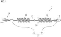
- FIG. 1 illustrates an optical fiber cable 1 according to the present embodiment.
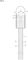
- FIG. 2 is a view illustrating an end portion of the optical fiber cable 1.
- the optical fiber cable 1 of the present embodiment is an optical fiber cable for pneumatic feeding for which an installation work is performed by pneumatic feeding.
- the optical fiber cable 1 includes a cable main body 2 and a connecting member 3.
- the cable main body 2 is provided therein with a plurality of optical fibers 21 each having a plurality of core portions 211.
- the connecting member 3 is provided at a first end portion of the cable main body 2 and, upon connection with another optical fiber cable (not shown), holds the optical fibers 21 each having a plurality of core portions 211 described below and optical fibers 21 of another optical fiber cable to be connectable.
- the optical fiber cable 1 further includes a protective tube 4.
- the protective tube 4 is provided at the first end portion of the cable main body 2.
- the protective tube 4 is made of, for example, metal, and is provided to cover the connecting member 3.
- the protective tube 4 protects the first end portion of the cable main body 2 and the connecting member 3 from damage when installing the optical fiber cable 1 by pneumatic feeding.
- FIG. 3 is a cross-sectional view of the cable main body 2.
- the cable main body 2 includes, for example, a plurality of optical fibers 21 constituting a plurality of optical fiber ribbons 20, a water-absorbing tape 22, a cable sheath 23, at least one tensile strength member 24, at least one tear cord 25 (fibrous filler), and a plurality of projections 26.
- the tensile strength member 24 is arranged along a longitudinal direction of the cable main body 2.
- a diameter of the tensile strength member 24 is, for example, 0.5 mm.
- the tensile strength member 24 is formed of, for example, fiber-reinforced plastic (FRP) such as aramid FRP, glass FRP, and carbon FRP.
- FRP fiber-reinforced plastic
- the tensile strength member 24 may also be formed of liquid crystal polymer.
- the tensile strength member 24 preferably has a non-inductive property. Note that fiber-reinforced plastic (FRP) is generally a flammable material.
- the tear cord 25 is provided for tearing the cable sheath 23.
- the tear cord 25 is provided in the cable sheath 23 along the longitudinal direction of the cable main body 2.
- two tear cords 25 are provided.
- the two tear cords 25 are arranged to face each other, for example, across the center of the cable main body 2.
- the tear cord 25 is made of a fibrous material, for example, a plastic material (for example, polyester) that is resistant to tension.
- the cable main body 2 includes the tensile strength members 24, in addition to the multi-core fibers and the cable sheath 23.
- the optical fiber cable 1 has a certain rigidity, it is difficult for the optical fiber cable to kink even when installed by pneumatic feeding.
- the optical fiber cable 1 includes the connecting member 3 for a multi-core fiber provided at the first end portion of the cable main body 2.
- An aligning work for connecting the multi-core fibers during fusion-splicing becomes unnecessary at the first end portion where the connecting member 3 is provided, and a work for providing a connector or the like at the terminal of the optical fiber cable 1 after installation becomes unnecessary.
- a curl outer diameter D1 which is a helical outer diameter of the curled portion 2a, is preferably 50 mm or greater and 300 mm or less.
- the curl outer diameter is too small, transmission loss of the optical fiber cable 1 may increase due to curl processing.
- the curl outer diameter is too large, an outer diameter of the entire optical fiber cable 1 increases, so the workability of installation by pneumatic feeding may decrease.
- the connecting member 3 provided at the second end portion of the cable main body 2, which is different from the first end portion where the protective tube 4 is provided, is a convertor 32.
- the convertor 32 keeps the optical fiber cable 1, which includes multi-core fibers therein, and an optical fiber cable 1A, which includes single-core fibers therein, to be connectable.
- FIG. 5 is a schematic view for illustrating the convertor 32.
- the convertor 32 holds the multi-core optical fibers 21 by inserting the multi-core optical fibers 21 therein.
- the convertor 32 is configured to connect a single-core optical fiber 21A having a single core portion to each core portion 211 (see FIG. 4 ) of the multi-core fiber.
- the convertor 32 exposes the single-core optical fibers 21A in a direction on an opposite side to a direction in which the convertor 32 receives insertion of the multi-core optical fibers 21.
- the number of core portions is preferably the same.
- 12 single-core optical fibers 21A are preferably connected to the convertor 32.
- the 12 single-core optical fibers 21A connected to the convertor 32 may constitute an optical fiber ribbon composed of 12-core optical fiber 21A.
- the 12-core optical fiber ribbon may be an intermittent connection-type optical fiber ribbon in which connected portions and non-connected portions are alternately provided. In the connection portion, adjacent optical fibers 21A are connected to each other. In the non-connected portion, adjacent optical fibers 21A are spaced apart from each other.
Landscapes
- Physics & Mathematics (AREA)
- General Physics & Mathematics (AREA)
- Optics & Photonics (AREA)
- Mechanical Coupling Of Light Guides (AREA)
- Light Guides In General And Applications Therefor (AREA)
Applications Claiming Priority (2)
| Application Number | Priority Date | Filing Date | Title |
|---|---|---|---|
| JP2022003066 | 2022-01-12 | ||
| PCT/JP2023/000456 WO2023136263A1 (ja) | 2022-01-12 | 2023-01-11 | 光ファイバケーブル |
Publications (2)
| Publication Number | Publication Date |
|---|---|
| EP4465102A1 true EP4465102A1 (de) | 2024-11-20 |
| EP4465102A4 EP4465102A4 (de) | 2025-04-16 |
Family
ID=87279153
Family Applications (1)
| Application Number | Title | Priority Date | Filing Date |
|---|---|---|---|
| EP23740272.2A Pending EP4465102A4 (de) | 2022-01-12 | 2023-01-11 | Faseroptisches kabel |
Country Status (4)
| Country | Link |
|---|---|
| US (1) | US20250102753A1 (de) |
| EP (1) | EP4465102A4 (de) |
| JP (1) | JPWO2023136263A1 (de) |
| WO (1) | WO2023136263A1 (de) |
Family Cites Families (10)
| Publication number | Priority date | Publication date | Assignee | Title |
|---|---|---|---|---|
| JP2005292205A (ja) * | 2004-03-31 | 2005-10-20 | Sumitomo Electric Ind Ltd | 光ファイバケーブル及び光ファイバケーブルの布設方法 |
| JP5497544B2 (ja) * | 2010-06-09 | 2014-05-21 | 住友電気工業株式会社 | コネクタ付集合光ケーブル |
| CN105026965A (zh) * | 2013-01-10 | 2015-11-04 | 住友电气工业株式会社 | 光学部件及光通信系统 |
| WO2014121034A1 (en) * | 2013-02-01 | 2014-08-07 | Commscope, Inc. Of North Carolina | Transitioning multi-core fiber to plural single core fibers |
| JP2015052704A (ja) * | 2013-09-06 | 2015-03-19 | 住友電気工業株式会社 | 光ファイバテープ心線、光ケーブル、光ファイバコード、及びテープ心線接続方法 |
| US9664864B2 (en) * | 2015-10-09 | 2017-05-30 | Commscope Technologies Llc | Method for terminating high fiber count cables |
| EP3386951B1 (de) | 2015-12-09 | 2020-02-26 | H. Hoffnabb-La Roche Ag | Phenylderivate als cannabinoidrezeptor-2-agonisten |
| US11762161B2 (en) * | 2019-06-19 | 2023-09-19 | Sumitomo Electric Industries, Ltd. | Optical fiber cable |
| JP7156181B2 (ja) | 2019-06-19 | 2022-10-19 | 住友電気工業株式会社 | 光ファイバケーブル |
| EP4279965A4 (de) * | 2021-01-12 | 2024-06-05 | Sumitomo Electric Industries, Ltd. | Faseroptisches kabel und kabel mit verbinder |
-
2023
- 2023-01-11 US US18/727,877 patent/US20250102753A1/en active Pending
- 2023-01-11 JP JP2023574047A patent/JPWO2023136263A1/ja active Pending
- 2023-01-11 EP EP23740272.2A patent/EP4465102A4/de active Pending
- 2023-01-11 WO PCT/JP2023/000456 patent/WO2023136263A1/ja not_active Ceased
Also Published As
| Publication number | Publication date |
|---|---|
| JPWO2023136263A1 (de) | 2023-07-20 |
| EP4465102A4 (de) | 2025-04-16 |
| WO2023136263A1 (ja) | 2023-07-20 |
| US20250102753A1 (en) | 2025-03-27 |
Similar Documents
| Publication | Publication Date | Title |
|---|---|---|
| EP1831746B1 (de) | Verteilerkabel mit umgossener mittelspannenzugangsstelle mit präferenzneigung | |
| JP4733115B2 (ja) | 複合成形中間分岐点を有する配線ケーブル組立体 | |
| JP4017990B2 (ja) | 光ファイバ用分岐装置 | |
| US20090087148A1 (en) | Optical fiber cables | |
| US7660501B2 (en) | Distribution cable assembly having overmolded mid-span access location | |
| US7703990B1 (en) | Furcation bodies and fiber optic assemblies using the same | |
| US20100220964A1 (en) | Fiber Optic Drop Cable Furcation Assemblies and Methods | |
| JP7800448B2 (ja) | 光ファイバケーブル及びコネクタ付きケーブル | |
| US20230244050A1 (en) | Optical fiber cable and cable with connector | |
| WO2021199736A1 (ja) | 収容構造体、牽引端付き光ケーブル及び収容構造体の製造方法 | |
| EP4220260A1 (de) | Faseroptisches kabel und kabel mit verbinder | |
| US7778511B1 (en) | Optical fiber cables | |
| EP4465102A1 (de) | Faseroptisches kabel | |
| JP7845195B2 (ja) | コネクタ付きケーブル | |
| CN213399003U (zh) | 一种双芯扁形室内用复合光缆 | |
| EP4227720B1 (de) | Optisches kabel | |
| JP3991204B2 (ja) | 光ファイバコード付き多心光コネクタ | |
| US20240319466A1 (en) | Optical fiber cable | |
| WO2022249756A1 (ja) | 光ファイバケーブル | |
| US20090087152A1 (en) | Optical Cable, Arrangement for Connecting a Multiplicity of Optical Waveguides, and Method for Manufacturing an Optical Cable | |
| US20250102754A1 (en) | Optical fiber cable | |
| CN215181104U (zh) | 一种小型多功能光缆 | |
| CN211554409U (zh) | 具有子单元设计的光缆组件 | |
| JP3006595B1 (ja) | 金属管型光ファイバケーブルの光コネクタ付き端末部 | |
| CA2639818C (en) | Optical fiber cables |
Legal Events
| Date | Code | Title | Description |
|---|---|---|---|
| STAA | Information on the status of an ep patent application or granted ep patent |
Free format text: STATUS: THE INTERNATIONAL PUBLICATION HAS BEEN MADE |
|
| PUAI | Public reference made under article 153(3) epc to a published international application that has entered the european phase |
Free format text: ORIGINAL CODE: 0009012 |
|
| STAA | Information on the status of an ep patent application or granted ep patent |
Free format text: STATUS: REQUEST FOR EXAMINATION WAS MADE |
|
| 17P | Request for examination filed |
Effective date: 20240711 |
|
| AK | Designated contracting states |
Kind code of ref document: A1 Designated state(s): AL AT BE BG CH CY CZ DE DK EE ES FI FR GB GR HR HU IE IS IT LI LT LU LV MC ME MK MT NL NO PL PT RO RS SE SI SK SM TR |
|
| A4 | Supplementary search report drawn up and despatched |
Effective date: 20250319 |
|
| DAV | Request for validation of the european patent (deleted) | ||
| DAX | Request for extension of the european patent (deleted) | ||
| RIC1 | Information provided on ipc code assigned before grant |
Ipc: G02B 6/52 20060101ALI20250313BHEP Ipc: G02B 6/36 20060101ALI20250313BHEP Ipc: G02B 6/02 20060101ALI20250313BHEP Ipc: G02B 6/44 20060101AFI20250313BHEP |