EP4464901A1 - Steuersystem für einen stellzylinder - Google Patents
Steuersystem für einen stellzylinder Download PDFInfo
- Publication number
- EP4464901A1 EP4464901A1 EP24175624.6A EP24175624A EP4464901A1 EP 4464901 A1 EP4464901 A1 EP 4464901A1 EP 24175624 A EP24175624 A EP 24175624A EP 4464901 A1 EP4464901 A1 EP 4464901A1
- Authority
- EP
- European Patent Office
- Prior art keywords
- chamber
- supply conduit
- conduit
- regeneration
- valve
- Prior art date
- Legal status (The legal status is an assumption and is not a legal conclusion. Google has not performed a legal analysis and makes no representation as to the accuracy of the status listed.)
- Pending
Links
Images


Classifications
-
- F—MECHANICAL ENGINEERING; LIGHTING; HEATING; WEAPONS; BLASTING
- F15—FLUID-PRESSURE ACTUATORS; HYDRAULICS OR PNEUMATICS IN GENERAL
- F15B—SYSTEMS ACTING BY MEANS OF FLUIDS IN GENERAL; FLUID-PRESSURE ACTUATORS, e.g. SERVOMOTORS; DETAILS OF FLUID-PRESSURE SYSTEMS, NOT OTHERWISE PROVIDED FOR
- F15B11/00—Servomotor systems without provision for follow-up action; Circuits therefor
- F15B11/02—Systems essentially incorporating special features for controlling the speed or actuating force of an output member
- F15B11/024—Systems essentially incorporating special features for controlling the speed or actuating force of an output member by means of differential connection of the servomotor lines, e.g. regenerative circuits
-
- F—MECHANICAL ENGINEERING; LIGHTING; HEATING; WEAPONS; BLASTING
- F15—FLUID-PRESSURE ACTUATORS; HYDRAULICS OR PNEUMATICS IN GENERAL
- F15B—SYSTEMS ACTING BY MEANS OF FLUIDS IN GENERAL; FLUID-PRESSURE ACTUATORS, e.g. SERVOMOTORS; DETAILS OF FLUID-PRESSURE SYSTEMS, NOT OTHERWISE PROVIDED FOR
- F15B11/00—Servomotor systems without provision for follow-up action; Circuits therefor
- F15B11/02—Systems essentially incorporating special features for controlling the speed or actuating force of an output member
- F15B11/024—Systems essentially incorporating special features for controlling the speed or actuating force of an output member by means of differential connection of the servomotor lines, e.g. regenerative circuits
- F15B2011/0243—Systems essentially incorporating special features for controlling the speed or actuating force of an output member by means of differential connection of the servomotor lines, e.g. regenerative circuits the regenerative circuit being activated or deactivated automatically
-
- F—MECHANICAL ENGINEERING; LIGHTING; HEATING; WEAPONS; BLASTING
- F15—FLUID-PRESSURE ACTUATORS; HYDRAULICS OR PNEUMATICS IN GENERAL
- F15B—SYSTEMS ACTING BY MEANS OF FLUIDS IN GENERAL; FLUID-PRESSURE ACTUATORS, e.g. SERVOMOTORS; DETAILS OF FLUID-PRESSURE SYSTEMS, NOT OTHERWISE PROVIDED FOR
- F15B11/00—Servomotor systems without provision for follow-up action; Circuits therefor
- F15B11/02—Systems essentially incorporating special features for controlling the speed or actuating force of an output member
- F15B11/024—Systems essentially incorporating special features for controlling the speed or actuating force of an output member by means of differential connection of the servomotor lines, e.g. regenerative circuits
- F15B2011/0246—Systems essentially incorporating special features for controlling the speed or actuating force of an output member by means of differential connection of the servomotor lines, e.g. regenerative circuits with variable regeneration flow
-
- F—MECHANICAL ENGINEERING; LIGHTING; HEATING; WEAPONS; BLASTING
- F15—FLUID-PRESSURE ACTUATORS; HYDRAULICS OR PNEUMATICS IN GENERAL
- F15B—SYSTEMS ACTING BY MEANS OF FLUIDS IN GENERAL; FLUID-PRESSURE ACTUATORS, e.g. SERVOMOTORS; DETAILS OF FLUID-PRESSURE SYSTEMS, NOT OTHERWISE PROVIDED FOR
- F15B2211/00—Circuits for servomotor systems
- F15B2211/30—Directional control
- F15B2211/305—Directional control characterised by the type of valves
- F15B2211/3056—Assemblies of multiple valves
- F15B2211/30565—Assemblies of multiple valves having multiple valves for a single output member, e.g. for creating higher valve function by use of multiple valves like two 2/2-valves replacing a 5/3-valve
- F15B2211/3058—Assemblies of multiple valves having multiple valves for a single output member, e.g. for creating higher valve function by use of multiple valves like two 2/2-valves replacing a 5/3-valve having additional valves for interconnecting the fluid chambers of a double-acting actuator, e.g. for regeneration mode or for floating mode
-
- F—MECHANICAL ENGINEERING; LIGHTING; HEATING; WEAPONS; BLASTING
- F15—FLUID-PRESSURE ACTUATORS; HYDRAULICS OR PNEUMATICS IN GENERAL
- F15B—SYSTEMS ACTING BY MEANS OF FLUIDS IN GENERAL; FLUID-PRESSURE ACTUATORS, e.g. SERVOMOTORS; DETAILS OF FLUID-PRESSURE SYSTEMS, NOT OTHERWISE PROVIDED FOR
- F15B2211/00—Circuits for servomotor systems
- F15B2211/30—Directional control
- F15B2211/31—Directional control characterised by the positions of the valve element
- F15B2211/3144—Directional control characterised by the positions of the valve element the positions being continuously variable, e.g. as realised by proportional valves
-
- F—MECHANICAL ENGINEERING; LIGHTING; HEATING; WEAPONS; BLASTING
- F15—FLUID-PRESSURE ACTUATORS; HYDRAULICS OR PNEUMATICS IN GENERAL
- F15B—SYSTEMS ACTING BY MEANS OF FLUIDS IN GENERAL; FLUID-PRESSURE ACTUATORS, e.g. SERVOMOTORS; DETAILS OF FLUID-PRESSURE SYSTEMS, NOT OTHERWISE PROVIDED FOR
- F15B2211/00—Circuits for servomotor systems
- F15B2211/30—Directional control
- F15B2211/32—Directional control characterised by the type of actuation
- F15B2211/329—Directional control characterised by the type of actuation actuated by fluid pressure
-
- F—MECHANICAL ENGINEERING; LIGHTING; HEATING; WEAPONS; BLASTING
- F15—FLUID-PRESSURE ACTUATORS; HYDRAULICS OR PNEUMATICS IN GENERAL
- F15B—SYSTEMS ACTING BY MEANS OF FLUIDS IN GENERAL; FLUID-PRESSURE ACTUATORS, e.g. SERVOMOTORS; DETAILS OF FLUID-PRESSURE SYSTEMS, NOT OTHERWISE PROVIDED FOR
- F15B2211/00—Circuits for servomotor systems
- F15B2211/50—Pressure control
- F15B2211/505—Pressure control characterised by the type of pressure control means
- F15B2211/50563—Pressure control characterised by the type of pressure control means the pressure control means controlling a differential pressure
- F15B2211/50581—Pressure control characterised by the type of pressure control means the pressure control means controlling a differential pressure using counterbalance valves
- F15B2211/5059—Pressure control characterised by the type of pressure control means the pressure control means controlling a differential pressure using counterbalance valves using double counterbalance valves
-
- F—MECHANICAL ENGINEERING; LIGHTING; HEATING; WEAPONS; BLASTING
- F15—FLUID-PRESSURE ACTUATORS; HYDRAULICS OR PNEUMATICS IN GENERAL
- F15B—SYSTEMS ACTING BY MEANS OF FLUIDS IN GENERAL; FLUID-PRESSURE ACTUATORS, e.g. SERVOMOTORS; DETAILS OF FLUID-PRESSURE SYSTEMS, NOT OTHERWISE PROVIDED FOR
- F15B2211/00—Circuits for servomotor systems
- F15B2211/60—Circuit components or control therefor
- F15B2211/63—Electronic controllers
- F15B2211/6303—Electronic controllers using input signals
- F15B2211/6306—Electronic controllers using input signals representing a pressure
-
- F—MECHANICAL ENGINEERING; LIGHTING; HEATING; WEAPONS; BLASTING
- F15—FLUID-PRESSURE ACTUATORS; HYDRAULICS OR PNEUMATICS IN GENERAL
- F15B—SYSTEMS ACTING BY MEANS OF FLUIDS IN GENERAL; FLUID-PRESSURE ACTUATORS, e.g. SERVOMOTORS; DETAILS OF FLUID-PRESSURE SYSTEMS, NOT OTHERWISE PROVIDED FOR
- F15B2211/00—Circuits for servomotor systems
- F15B2211/60—Circuit components or control therefor
- F15B2211/63—Electronic controllers
- F15B2211/6303—Electronic controllers using input signals
- F15B2211/632—Electronic controllers using input signals representing a flow rate
-
- F—MECHANICAL ENGINEERING; LIGHTING; HEATING; WEAPONS; BLASTING
- F15—FLUID-PRESSURE ACTUATORS; HYDRAULICS OR PNEUMATICS IN GENERAL
- F15B—SYSTEMS ACTING BY MEANS OF FLUIDS IN GENERAL; FLUID-PRESSURE ACTUATORS, e.g. SERVOMOTORS; DETAILS OF FLUID-PRESSURE SYSTEMS, NOT OTHERWISE PROVIDED FOR
- F15B2211/00—Circuits for servomotor systems
- F15B2211/60—Circuit components or control therefor
- F15B2211/63—Electronic controllers
- F15B2211/6303—Electronic controllers using input signals
- F15B2211/6346—Electronic controllers using input signals representing a state of input means, e.g. joystick position
-
- F—MECHANICAL ENGINEERING; LIGHTING; HEATING; WEAPONS; BLASTING
- F15—FLUID-PRESSURE ACTUATORS; HYDRAULICS OR PNEUMATICS IN GENERAL
- F15B—SYSTEMS ACTING BY MEANS OF FLUIDS IN GENERAL; FLUID-PRESSURE ACTUATORS, e.g. SERVOMOTORS; DETAILS OF FLUID-PRESSURE SYSTEMS, NOT OTHERWISE PROVIDED FOR
- F15B2211/00—Circuits for servomotor systems
- F15B2211/60—Circuit components or control therefor
- F15B2211/665—Methods of control using electronic components
-
- F—MECHANICAL ENGINEERING; LIGHTING; HEATING; WEAPONS; BLASTING
- F15—FLUID-PRESSURE ACTUATORS; HYDRAULICS OR PNEUMATICS IN GENERAL
- F15B—SYSTEMS ACTING BY MEANS OF FLUIDS IN GENERAL; FLUID-PRESSURE ACTUATORS, e.g. SERVOMOTORS; DETAILS OF FLUID-PRESSURE SYSTEMS, NOT OTHERWISE PROVIDED FOR
- F15B2211/00—Circuits for servomotor systems
- F15B2211/70—Output members, e.g. hydraulic motors or cylinders or control therefor
- F15B2211/705—Output members, e.g. hydraulic motors or cylinders or control therefor characterised by the type of output members or actuators
- F15B2211/7051—Linear output members
- F15B2211/7053—Double-acting output members
Definitions
- the present invention relates to the field of a control system for controlling an actuator cylinder in a hydraulic application.
- Control systems for hydraulic cylinders for moving the booms of telehandler and crane-type machines have evolved more and more over the years and require to fulfill an increasing number of functions.
- They require high safety so that in the event of a pipeline rupture, the system is able to control the actuator cylinder and stop it, preventing a possible load fall.
- high stability of the system is required so that the user can ensure that he or she can control the system without generating sudden jerks, which could cause the user a sense of discomfort.
- Control systems with a regenerative function are usually used to enable such a reduction in consumption and at the same time increase the speed of movement of the actuating cylinder.
- An example of such a system is shown in Figure 1 .
- valves with a regenerative function are used to increase the supply flow rate of an hydraulic cylinder and, consequently, the output speed of the cylinder.
- the cylinder comprising a first chamber 11 and a second chamber 12 separated by a piston 13, which is configured to move an element, such as an end portion of a crane, at which a load can be attached.
- the system shown in the figure includes a first feed conduit 20 of said first chamber 11 of said cylinder 10, a second feed conduit 21 of said second chamber 12 of said cylinder 10.
- Said first supply conduit 20 and said second supply conduit 21 are connectable to a distribution valve 100 configured to control a feed operation and a discharge operation of said first supply conduit 20 and said second supply conduit 21.
- Said first supply conduit 20 is connected to said second supply conduit 21 by means of a regeneration conduit 22 configured to allow a flow of fluid from said second chamber 12 to said first chamber 11 via said first and said second supply conduits 20, 21.
- a regeneration conduit 22 configured to allow a flow of fluid from said second chamber 12 to said first chamber 11 via said first and said second supply conduits 20, 21.
- a balancing valve 31 which is configured to regulate the flow of fluid along said regeneration conduit by means of pilot ports which, as shown in the figure, allow it to "see” the pressure present in both the first and second supply conduits.
- unidirectional valve 32 allows it to ensure fluid flow from the second to the first supply duct and prevent reverse flow.
- the one-way valve 33 makes it possible to ensure that all the fluid leaving the second chamber 12 goes to the first chamber and does not go to the outlet of the distribution valve 100.
- regeneration takes place using fluid exiting from the "stem side” (i.e., from the second chamber 12) that is sent to the bottom side (first chamber 11) in addition to the QP flow rate supplied by the machine's supply system.
- valve 31 that opens the regeneration duct.
- throttling is a purely temporal function.
- the present invention addresses the problem of realizing method of regulating the actuator cylinder that can overcome the disadvantages of the solutions adopted so far and thus provide particularly sophisticated initial control.
- the present invention relates to a method of adjusting an actuator cylinder according to the characteristics listed in claim 1.
- the object of the invention is achieved by a method of providing a variable regeneration ratio according to the flow rate sent by the distributor and, therefore, the required output speed.
- FIG 3 shows a schematic of a control system for an actuator cylinder 10 according to a form of embodiment of the present invention.
- the cylinder 10 is the same as shown in Figure 1 and thus comprises a first and second chambers 11, 12 and a piston 13 separating said first chamber 11 from said second chamber 10.
- Said actuator cylinder is configured to allow direct or indirect displacement of an element, to which a load can be attached.
- said actuator cylinder may be configured to move a mechanical arm such as the lifting arm of a telehandler or the boom of a crane, which is configured so as to be able to move loads (it is clear, however, that the load may be represented by the weight of the mechanical arm itself, which is moved unloaded and does not require the presence of an external body).
- the first and second chambers 11, 12 of the cylinder are located, respectively.
- the first and second chambers are fed by the first and second supply ducts 20, 21, respectively, which are connected to each other by regeneration duct 22.
- a balancing valve 30 is located along the first supply duct, which is completely similar to the one shown in Figure 1 .
- balancing valve 30 includes a one-way valve placed parallel to a balancing valve itself.
- a balancing valve was referred to generically because the one-way valve can be placed internally to the balancing valve itself. Therefore, two separate and distinct elements are not necessary But the two elements can be integrated into the same element.
- a balancing valve 98 is positioned along the second supply duct 21 which is configured to regulate the flow rate leaving the second chamber 12 and directed toward the distribution valve 100 and the flow rate directed in the opposite direction.
- balancing valve 98 consists of two elements: a one-way valve placed parallel to a balancing valve itself. Again, however, the two elements can be integrated into a single element having as its function that of the balancing valve.
- the balancing valve 98 receives the pressure at point V1 that will allow it to open the discharge to the distribution valve 100 in the event that a pressure is detected at point V1 of the first supply duct 20.
- the balancing valve 98 has an integrated pressure limiting function.
- the one-way valve makes it possible to ensure that a flow from the distribution valve 100 reaches the second chamber 12.
- the control element 99 consists of a single valve having two positions and three ways that can be adjusted proportionally between said two positions.
- a first position shown on the left of figure 3
- the valve 99 allows a flow of fluid between the second chamber 12 and the first duct 20 via the regeneration duct and prevents a flow of fluid between the second chamber and the second duct 21.
- a second position shown on the right of Figure 3
- valve 99 prevents a flow of fluid between the second chamber 12 and the first conduit 20 via the regeneration conduit and instead allows a flow of fluid between the second chamber and the second conduit 21.
- valve 99 is capable of taking intermediate positions between the two described allowing partial fluid passage in either direction.
- Valve 99 receives inlet pressures upstream and downstream of balancing valve 30. Specifically, the two pressures are routed through pilot channels at opposite ends of valve 99 so that an increase in flow rate will go to increase the flow area of valve 99, so that the flow rate passing from the second chamber 12 to the first chamber 11 via regeneration duct 22 will increase.
- one-way valve 97 also receives the pilot signal from V1 so that an increase in pressure along the first supply duct will go to promote a regeneration. With the opening of the regeneration duct 22 will then go to regeneration by going to decrease the pressure at the balancing valve 98 which will then gradually go to close.
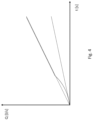
- figure 4 shows, as also figure 2 , the trend of the two flow rates QP (dotted) and QT, where the dotted line shows the trend of QT according to the state of the art while the solid line shows a possible trend of QT according to a form of embodiment of the present invention.
- QT grows proportionally with the incoming QP flow rate from the distribution valve 100. However, the proportionality varies with time and in particular increases with increasing QP flow rate.
- a request for displacement of said element is received, wherein displacement of said element results in an increase in volume of said first chamber 11 and a subsequent decrease in volume of said second chamber 12.
- a flow of fluid is provided from said distribution valve 100 through said first supply conduit to said first chamber 11 so as to be able to increase the volume of said first chamber 11 and to decrease the volume of said second chamber 12.
- regeneration conduit 22 is at least partially closed and at the same time said second supply conduit is opened so as to allow a discharge of fluid from said second chamber 12 to said distribution valve 100.
- Said regeneration conduit 22 is then gradually opened so as to allow at least partially an increase in fluid flow of the fluid contained in said second chamber 12 to said first chamber 11 based on said fluid flow rate coming from said distribution valve 100 and directed to said first chamber 11 via said first supply conduit 20 or said magnitude dependent thereon. Simultaneously said second supply conduit 21 is then progressively closed, going to decrease the discharge flow rate to distribution valve 100.
- Said condition may, for example, consist in the attainment of a predetermined speed of said piston 13 or a magnitude dependent thereon or a predetermined time interval elapsed since the opening of said regeneration duct 22.
- valve 99 can be replaced by two or more smaller valves capable of performing the same function. Furthermore, it is clear that as an alternative to the first hydraulic-type valve 99 shown in the figure, it can be a solenoid valve, which then receives an electrical actuation command based on the measured flow rate or said quantity dependent on it. Furthermore, although two pressure values were measured upstream and downstream of balancing valve 30 to measure the flow rate, it is clear to the branch expert that pressure can be detected at any other points, for example, both points may be upstream or both downstream of balancing valve 20. Furthermore, although an example was shown for which the flow rate was measured indirectly by means of pressure at two different points, it is clear that alternatively the flow rate can be detected directly by means of a flow detector.
- the above-described solution is particularly advantageous in that it allows not only to limit at an early stage the speed of piston displacement but likewise to allow superfluous flow rate that is not required for regeneration to be discharged through the balancing valve 98.
- the present invention also relates to a computational unit containing means for performing a method according to one of the previously described forms of embodiment.
- the present invention further relates to an actuator system of an actuator cylinder 10 of an operating machine, said actuator cylinder having a first and a second chamber 11, 12, a piston 13 separating said first chamber 11 from said second chamber 12 configured to move an element, said actuator system comprising a first feed conduit 20 of said first chamber 11 of said cylinder, a second feed conduit 21 of said second chamber 12 of said cylinder 10, wherein said first feed conduit 20 and said second feed conduit 21 are connectable to a distribution valve 100 configured to control a feed operation and a discharge operation of said first feed conduit 20 and said second feed conduit 21, wherein said first feed conduit 20 is connected to said second feed conduit 21 by means of a regeneration conduit 22 configured to allow a flow of fluid from said second chamber 12 to said first chamber 11 via said first and said second feed conduit 20, 21, wherein said actuation system comprises a previously described computing unit.
- Part of the present invention also comprises a computer program comprising instructions which, when the program is executed by a computer, cause the computer to execute the method steps of one of the previously described embodiments.
- a computer-readable storage medium comprising instructions which, when executed by a computer, cause the computer to execute the method steps of one of the described forms of embodiment is also part of the present invention.
Landscapes
- Engineering & Computer Science (AREA)
- Physics & Mathematics (AREA)
- Fluid Mechanics (AREA)
- Mechanical Engineering (AREA)
- General Engineering & Computer Science (AREA)
- Fluid-Pressure Circuits (AREA)
Applications Claiming Priority (1)
| Application Number | Priority Date | Filing Date | Title |
|---|---|---|---|
| IT102023000009951A IT202300009951A1 (it) | 2023-05-17 | 2023-05-17 | Sistema di controllo per un cilindro attuatore |
Publications (1)
| Publication Number | Publication Date |
|---|---|
| EP4464901A1 true EP4464901A1 (de) | 2024-11-20 |
Family
ID=87418657
Family Applications (1)
| Application Number | Title | Priority Date | Filing Date |
|---|---|---|---|
| EP24175624.6A Pending EP4464901A1 (de) | 2023-05-17 | 2024-05-14 | Steuersystem für einen stellzylinder |
Country Status (2)
| Country | Link |
|---|---|
| EP (1) | EP4464901A1 (de) |
| IT (1) | IT202300009951A1 (de) |
Citations (4)
| Publication number | Priority date | Publication date | Assignee | Title |
|---|---|---|---|---|
| US4397221A (en) * | 1981-06-01 | 1983-08-09 | Deere & Company | Regenerative valve |
| DE19735482A1 (de) * | 1997-08-16 | 1999-02-18 | Mannesmann Rexroth Ag | Hydraulisches System mit einem Differentialzylinder und einem Eilgangventil sowie Eilgangventil für ein solches hydraulisches System |
| US6267041B1 (en) * | 1999-12-15 | 2001-07-31 | Caterpillar Inc. | Fluid regeneration circuit for hydraulic cylinders |
| DE102015209659A1 (de) * | 2015-05-27 | 2016-12-15 | Robert Bosch Gmbh | Hydraulische Anordnung zur Regeneration von Druckmittel eines hydraulischen Verbrauchers und hydraulisches System mit der hydraulischen Anordnung |
-
2023
- 2023-05-17 IT IT102023000009951A patent/IT202300009951A1/it unknown
-
2024
- 2024-05-14 EP EP24175624.6A patent/EP4464901A1/de active Pending
Patent Citations (4)
| Publication number | Priority date | Publication date | Assignee | Title |
|---|---|---|---|---|
| US4397221A (en) * | 1981-06-01 | 1983-08-09 | Deere & Company | Regenerative valve |
| DE19735482A1 (de) * | 1997-08-16 | 1999-02-18 | Mannesmann Rexroth Ag | Hydraulisches System mit einem Differentialzylinder und einem Eilgangventil sowie Eilgangventil für ein solches hydraulisches System |
| US6267041B1 (en) * | 1999-12-15 | 2001-07-31 | Caterpillar Inc. | Fluid regeneration circuit for hydraulic cylinders |
| DE102015209659A1 (de) * | 2015-05-27 | 2016-12-15 | Robert Bosch Gmbh | Hydraulische Anordnung zur Regeneration von Druckmittel eines hydraulischen Verbrauchers und hydraulisches System mit der hydraulischen Anordnung |
Also Published As
| Publication number | Publication date |
|---|---|
| IT202300009951A1 (it) | 2024-11-17 |
Similar Documents
| Publication | Publication Date | Title |
|---|---|---|
| US9181070B2 (en) | Hydraulic driving apparatus for working machine | |
| US6837140B2 (en) | Control system and method for hydraulic working machine | |
| US9200646B2 (en) | Control arrangement and method for activating a plurality of hydraulic consumers | |
| US10393151B2 (en) | Hydraulic drive system for working machine | |
| US20220275605A1 (en) | Hydraulic control system | |
| JPH01250602A (ja) | 液力式の切換装置 | |
| JP5707287B2 (ja) | 作業機械の油圧駆動装置 | |
| JP2007247897A (ja) | アクチュエータに捕捉された圧力を解放するための機構を有する油圧システム | |
| WO2018202659A1 (en) | Vehicle with a boom comprising a hydraulic control circuit with a load control valve | |
| US5433077A (en) | Actuator control device with meter-out valve | |
| CN105247224B (zh) | 液压阀安排 | |
| EP4464901A1 (de) | Steuersystem für einen stellzylinder | |
| JP3552735B2 (ja) | 建設機械の油圧回路 | |
| JPS60263705A (ja) | 液圧装置のための圧力供給装置 | |
| JP2000255988A (ja) | 液圧作業機械のアクチュエータ制御回路 | |
| CN102803747A (zh) | 阀装置 | |
| EP4325068B1 (de) | Steuersystem für einen stellzylinder | |
| JP3766972B2 (ja) | 建設機械の油圧回路 | |
| JP5890040B2 (ja) | 油圧システムにおける電子油圧ポンプの圧力オーバーシュート防止システム | |
| EP4647610A1 (de) | Steuersystem für einen stellzylinder | |
| JP3659654B2 (ja) | 建設機械の油圧回路 | |
| JP2631125B2 (ja) | 負荷圧補償ポンプ吐出流量制御回路 | |
| EP4095393A1 (de) | Hydraulischer verteiler mit ausgleichsvorrichtung für wegeventile und hydraulikkreislauf diesen umfassend | |
| JPH04119604U (ja) | ロードセンシング油圧回路 | |
| JPH047369Y2 (de) |
Legal Events
| Date | Code | Title | Description |
|---|---|---|---|
| PUAI | Public reference made under article 153(3) epc to a published international application that has entered the european phase |
Free format text: ORIGINAL CODE: 0009012 |
|
| STAA | Information on the status of an ep patent application or granted ep patent |
Free format text: STATUS: THE APPLICATION HAS BEEN PUBLISHED |
|
| AK | Designated contracting states |
Kind code of ref document: A1 Designated state(s): AL AT BE BG CH CY CZ DE DK EE ES FI FR GB GR HR HU IE IS IT LI LT LU LV MC ME MK MT NL NO PL PT RO RS SE SI SK SM TR |
|
| STAA | Information on the status of an ep patent application or granted ep patent |
Free format text: STATUS: REQUEST FOR EXAMINATION WAS MADE |
|
| 17P | Request for examination filed |
Effective date: 20250520 |