EP4464899A1 - Vakuumpumpe, drehkörper für vakuumpumpe und verfahren zur herstellung einer vakuumpumpe - Google Patents
Vakuumpumpe, drehkörper für vakuumpumpe und verfahren zur herstellung einer vakuumpumpe Download PDFInfo
- Publication number
- EP4464899A1 EP4464899A1 EP23740271.4A EP23740271A EP4464899A1 EP 4464899 A1 EP4464899 A1 EP 4464899A1 EP 23740271 A EP23740271 A EP 23740271A EP 4464899 A1 EP4464899 A1 EP 4464899A1
- Authority
- EP
- European Patent Office
- Prior art keywords
- component
- cylinder portion
- vacuum pump
- side cylinder
- rotating body
- Prior art date
- Legal status (The legal status is an assumption and is not a legal conclusion. Google has not performed a legal analysis and makes no representation as to the accuracy of the status listed.)
- Pending
Links
Images






Classifications
-
- F—MECHANICAL ENGINEERING; LIGHTING; HEATING; WEAPONS; BLASTING
- F04—POSITIVE - DISPLACEMENT MACHINES FOR LIQUIDS; PUMPS FOR LIQUIDS OR ELASTIC FLUIDS
- F04D—NON-POSITIVE-DISPLACEMENT PUMPS
- F04D9/00—Priming; Preventing vapour lock
- F04D9/04—Priming; Preventing vapour lock using priming pumps; using booster pumps to prevent vapour-lock
-
- F—MECHANICAL ENGINEERING; LIGHTING; HEATING; WEAPONS; BLASTING
- F04—POSITIVE - DISPLACEMENT MACHINES FOR LIQUIDS; PUMPS FOR LIQUIDS OR ELASTIC FLUIDS
- F04D—NON-POSITIVE-DISPLACEMENT PUMPS
- F04D19/00—Axial-flow pumps
- F04D19/02—Multi-stage pumps
- F04D19/04—Multi-stage pumps specially adapted to the production of a high vacuum, e.g. molecular pumps
- F04D19/042—Turbomolecular vacuum pumps
-
- B—PERFORMING OPERATIONS; TRANSPORTING
- B22—CASTING; POWDER METALLURGY
- B22F—WORKING METALLIC POWDER; MANUFACTURE OF ARTICLES FROM METALLIC POWDER; MAKING METALLIC POWDER; APPARATUS OR DEVICES SPECIALLY ADAPTED FOR METALLIC POWDER
- B22F10/00—Additive manufacturing of workpieces or articles from metallic powder
- B22F10/10—Formation of a green body
- B22F10/14—Formation of a green body by jetting of binder onto a bed of metal powder
-
- B—PERFORMING OPERATIONS; TRANSPORTING
- B22—CASTING; POWDER METALLURGY
- B22F—WORKING METALLIC POWDER; MANUFACTURE OF ARTICLES FROM METALLIC POWDER; MAKING METALLIC POWDER; APPARATUS OR DEVICES SPECIALLY ADAPTED FOR METALLIC POWDER
- B22F10/00—Additive manufacturing of workpieces or articles from metallic powder
- B22F10/10—Formation of a green body
- B22F10/18—Formation of a green body by mixing binder with metal in filament form, e.g. fused filament fabrication [FFF]
-
- B—PERFORMING OPERATIONS; TRANSPORTING
- B22—CASTING; POWDER METALLURGY
- B22F—WORKING METALLIC POWDER; MANUFACTURE OF ARTICLES FROM METALLIC POWDER; MAKING METALLIC POWDER; APPARATUS OR DEVICES SPECIALLY ADAPTED FOR METALLIC POWDER
- B22F10/00—Additive manufacturing of workpieces or articles from metallic powder
- B22F10/20—Direct sintering or melting
- B22F10/25—Direct deposition of metal particles, e.g. direct metal deposition [DMD] or laser engineered net shaping [LENS]
-
- B—PERFORMING OPERATIONS; TRANSPORTING
- B22—CASTING; POWDER METALLURGY
- B22F—WORKING METALLIC POWDER; MANUFACTURE OF ARTICLES FROM METALLIC POWDER; MAKING METALLIC POWDER; APPARATUS OR DEVICES SPECIALLY ADAPTED FOR METALLIC POWDER
- B22F10/00—Additive manufacturing of workpieces or articles from metallic powder
- B22F10/20—Direct sintering or melting
- B22F10/28—Powder bed fusion, e.g. selective laser melting [SLM] or electron beam melting [EBM]
-
- B—PERFORMING OPERATIONS; TRANSPORTING
- B22—CASTING; POWDER METALLURGY
- B22F—WORKING METALLIC POWDER; MANUFACTURE OF ARTICLES FROM METALLIC POWDER; MAKING METALLIC POWDER; APPARATUS OR DEVICES SPECIALLY ADAPTED FOR METALLIC POWDER
- B22F5/00—Manufacture of workpieces or articles from metallic powder characterised by the special shape of the product
- B22F5/10—Manufacture of workpieces or articles from metallic powder characterised by the special shape of the product of articles with cavities or holes, not otherwise provided for in the preceding subgroups
-
- B—PERFORMING OPERATIONS; TRANSPORTING
- B22—CASTING; POWDER METALLURGY
- B22F—WORKING METALLIC POWDER; MANUFACTURE OF ARTICLES FROM METALLIC POWDER; MAKING METALLIC POWDER; APPARATUS OR DEVICES SPECIALLY ADAPTED FOR METALLIC POWDER
- B22F7/00—Manufacture of composite layers, workpieces, or articles, comprising metallic powder, by sintering the powder, with or without compacting wherein at least one part is obtained by sintering or compression
- B22F7/06—Manufacture of composite layers, workpieces, or articles, comprising metallic powder, by sintering the powder, with or without compacting wherein at least one part is obtained by sintering or compression of composite workpieces or articles from parts, e.g. to form tipped tools
- B22F7/062—Manufacture of composite layers, workpieces, or articles, comprising metallic powder, by sintering the powder, with or without compacting wherein at least one part is obtained by sintering or compression of composite workpieces or articles from parts, e.g. to form tipped tools involving the connection or repairing of preformed parts
-
- B—PERFORMING OPERATIONS; TRANSPORTING
- B22—CASTING; POWDER METALLURGY
- B22F—WORKING METALLIC POWDER; MANUFACTURE OF ARTICLES FROM METALLIC POWDER; MAKING METALLIC POWDER; APPARATUS OR DEVICES SPECIALLY ADAPTED FOR METALLIC POWDER
- B22F7/00—Manufacture of composite layers, workpieces, or articles, comprising metallic powder, by sintering the powder, with or without compacting wherein at least one part is obtained by sintering or compression
- B22F7/06—Manufacture of composite layers, workpieces, or articles, comprising metallic powder, by sintering the powder, with or without compacting wherein at least one part is obtained by sintering or compression of composite workpieces or articles from parts, e.g. to form tipped tools
- B22F7/08—Manufacture of composite layers, workpieces, or articles, comprising metallic powder, by sintering the powder, with or without compacting wherein at least one part is obtained by sintering or compression of composite workpieces or articles from parts, e.g. to form tipped tools with one or more parts not made from powder
-
- B—PERFORMING OPERATIONS; TRANSPORTING
- B33—ADDITIVE MANUFACTURING TECHNOLOGY
- B33Y—ADDITIVE MANUFACTURING, i.e. MANUFACTURING OF THREE-DIMENSIONAL [3D] OBJECTS BY ADDITIVE DEPOSITION, ADDITIVE AGGLOMERATION OR ADDITIVE LAYERING, e.g. BY 3D PRINTING, STEREOLITHOGRAPHY OR SELECTIVE LASER SINTERING
- B33Y80/00—Products made by additive manufacturing
-
- F—MECHANICAL ENGINEERING; LIGHTING; HEATING; WEAPONS; BLASTING
- F04—POSITIVE - DISPLACEMENT MACHINES FOR LIQUIDS; PUMPS FOR LIQUIDS OR ELASTIC FLUIDS
- F04D—NON-POSITIVE-DISPLACEMENT PUMPS
- F04D19/00—Axial-flow pumps
- F04D19/02—Multi-stage pumps
- F04D19/04—Multi-stage pumps specially adapted to the production of a high vacuum, e.g. molecular pumps
-
- F—MECHANICAL ENGINEERING; LIGHTING; HEATING; WEAPONS; BLASTING
- F04—POSITIVE - DISPLACEMENT MACHINES FOR LIQUIDS; PUMPS FOR LIQUIDS OR ELASTIC FLUIDS
- F04D—NON-POSITIVE-DISPLACEMENT PUMPS
- F04D29/00—Details, component parts, or accessories
- F04D29/02—Selection of particular materials
- F04D29/023—Selection of particular materials especially adapted for elastic fluid pumps
-
- F—MECHANICAL ENGINEERING; LIGHTING; HEATING; WEAPONS; BLASTING
- F04—POSITIVE - DISPLACEMENT MACHINES FOR LIQUIDS; PUMPS FOR LIQUIDS OR ELASTIC FLUIDS
- F04D—NON-POSITIVE-DISPLACEMENT PUMPS
- F04D29/00—Details, component parts, or accessories
- F04D29/26—Rotors specially for elastic fluids
- F04D29/32—Rotors specially for elastic fluids for axial flow pumps
-
- F—MECHANICAL ENGINEERING; LIGHTING; HEATING; WEAPONS; BLASTING
- F04—POSITIVE - DISPLACEMENT MACHINES FOR LIQUIDS; PUMPS FOR LIQUIDS OR ELASTIC FLUIDS
- F04D—NON-POSITIVE-DISPLACEMENT PUMPS
- F04D29/00—Details, component parts, or accessories
- F04D29/26—Rotors specially for elastic fluids
- F04D29/32—Rotors specially for elastic fluids for axial flow pumps
- F04D29/321—Rotors specially for elastic fluids for axial flow pumps for axial flow compressors
-
- B—PERFORMING OPERATIONS; TRANSPORTING
- B22—CASTING; POWDER METALLURGY
- B22F—WORKING METALLIC POWDER; MANUFACTURE OF ARTICLES FROM METALLIC POWDER; MAKING METALLIC POWDER; APPARATUS OR DEVICES SPECIALLY ADAPTED FOR METALLIC POWDER
- B22F5/00—Manufacture of workpieces or articles from metallic powder characterised by the special shape of the product
- B22F2005/005—Article surface comprising protrusions
-
- B—PERFORMING OPERATIONS; TRANSPORTING
- B33—ADDITIVE MANUFACTURING TECHNOLOGY
- B33Y—ADDITIVE MANUFACTURING, i.e. MANUFACTURING OF THREE-DIMENSIONAL [3D] OBJECTS BY ADDITIVE DEPOSITION, ADDITIVE AGGLOMERATION OR ADDITIVE LAYERING, e.g. BY 3D PRINTING, STEREOLITHOGRAPHY OR SELECTIVE LASER SINTERING
- B33Y10/00—Processes of additive manufacturing
-
- F—MECHANICAL ENGINEERING; LIGHTING; HEATING; WEAPONS; BLASTING
- F05—INDEXING SCHEMES RELATING TO ENGINES OR PUMPS IN VARIOUS SUBCLASSES OF CLASSES F01-F04
- F05D—INDEXING SCHEME FOR ASPECTS RELATING TO NON-POSITIVE-DISPLACEMENT MACHINES OR ENGINES, GAS-TURBINES OR JET-PROPULSION PLANTS
- F05D2230/00—Manufacture
- F05D2230/20—Manufacture essentially without removing material
- F05D2230/21—Manufacture essentially without removing material by casting
-
- F—MECHANICAL ENGINEERING; LIGHTING; HEATING; WEAPONS; BLASTING
- F05—INDEXING SCHEMES RELATING TO ENGINES OR PUMPS IN VARIOUS SUBCLASSES OF CLASSES F01-F04
- F05D—INDEXING SCHEME FOR ASPECTS RELATING TO NON-POSITIVE-DISPLACEMENT MACHINES OR ENGINES, GAS-TURBINES OR JET-PROPULSION PLANTS
- F05D2230/00—Manufacture
- F05D2230/20—Manufacture essentially without removing material
- F05D2230/22—Manufacture essentially without removing material by sintering
-
- F—MECHANICAL ENGINEERING; LIGHTING; HEATING; WEAPONS; BLASTING
- F05—INDEXING SCHEMES RELATING TO ENGINES OR PUMPS IN VARIOUS SUBCLASSES OF CLASSES F01-F04
- F05D—INDEXING SCHEME FOR ASPECTS RELATING TO NON-POSITIVE-DISPLACEMENT MACHINES OR ENGINES, GAS-TURBINES OR JET-PROPULSION PLANTS
- F05D2230/00—Manufacture
- F05D2230/20—Manufacture essentially without removing material
- F05D2230/23—Manufacture essentially without removing material by permanently joining parts together
-
- F—MECHANICAL ENGINEERING; LIGHTING; HEATING; WEAPONS; BLASTING
- F05—INDEXING SCHEMES RELATING TO ENGINES OR PUMPS IN VARIOUS SUBCLASSES OF CLASSES F01-F04
- F05D—INDEXING SCHEME FOR ASPECTS RELATING TO NON-POSITIVE-DISPLACEMENT MACHINES OR ENGINES, GAS-TURBINES OR JET-PROPULSION PLANTS
- F05D2230/00—Manufacture
- F05D2230/20—Manufacture essentially without removing material
- F05D2230/24—Manufacture essentially without removing material by extrusion
-
- F—MECHANICAL ENGINEERING; LIGHTING; HEATING; WEAPONS; BLASTING
- F05—INDEXING SCHEMES RELATING TO ENGINES OR PUMPS IN VARIOUS SUBCLASSES OF CLASSES F01-F04
- F05D—INDEXING SCHEME FOR ASPECTS RELATING TO NON-POSITIVE-DISPLACEMENT MACHINES OR ENGINES, GAS-TURBINES OR JET-PROPULSION PLANTS
- F05D2230/00—Manufacture
- F05D2230/20—Manufacture essentially without removing material
- F05D2230/25—Manufacture essentially without removing material by forging
-
- F—MECHANICAL ENGINEERING; LIGHTING; HEATING; WEAPONS; BLASTING
- F05—INDEXING SCHEMES RELATING TO ENGINES OR PUMPS IN VARIOUS SUBCLASSES OF CLASSES F01-F04
- F05D—INDEXING SCHEME FOR ASPECTS RELATING TO NON-POSITIVE-DISPLACEMENT MACHINES OR ENGINES, GAS-TURBINES OR JET-PROPULSION PLANTS
- F05D2230/00—Manufacture
- F05D2230/30—Manufacture with deposition of material
- F05D2230/31—Layer deposition
-
- Y—GENERAL TAGGING OF NEW TECHNOLOGICAL DEVELOPMENTS; GENERAL TAGGING OF CROSS-SECTIONAL TECHNOLOGIES SPANNING OVER SEVERAL SECTIONS OF THE IPC; TECHNICAL SUBJECTS COVERED BY FORMER USPC CROSS-REFERENCE ART COLLECTIONS [XRACs] AND DIGESTS
- Y02—TECHNOLOGIES OR APPLICATIONS FOR MITIGATION OR ADAPTATION AGAINST CLIMATE CHANGE
- Y02P—CLIMATE CHANGE MITIGATION TECHNOLOGIES IN THE PRODUCTION OR PROCESSING OF GOODS
- Y02P10/00—Technologies related to metal processing
- Y02P10/25—Process efficiency
Definitions
- the present invention relates to a vacuum pump such as a turbo-molecular pump and the like, for example, a rotating body for vacuum pump, and a manufacturing method of vacuum pump.
- a turbo-molecular pump is known as one type of a vacuum pump.
- a rotor blade is rotated by energizing a motor inside a pump main body, and a gas is exhausted by flipping gas molecules of a gas (process gas) sucked into the pump main body.
- the turbo-molecular pump as above includes a type including a heater and a cooling pipe for properly controlling a temperature in the pump.
- the rotor blade for a turbo-molecular pump is provided on a motor-driven rotating body so as to protrude to a radial direction. Since the rotating body is rotated at a high speed, a large centrifugal force acts during the rotation. Thus, there are limiting conditions as below, for example, for the rotating body:
- the rotating body is entirely shaved out of a columnar material in many cases.
- a most part of the material 80% or more, for example is shaved out, which causes materials to be wasted.
- PTL 1 discloses an art of making a cylindrical rotor shaft (rotor shaft (15)) and a disc-shaped rotor disc (rotor disc 66) separately and of combining them.
- PTL 1 discloses three methods of combining the rotor shaft and the rotor disc as follows. However, each has its problem, and application of each of the methods is not easy.
- Method 1 The both (the rotor shaft (15) and the rotor disc (66)) are interference-fit (paragraphs 0028 and 0081).
- a ring-shaped component such as the rotor disc (66) can be easily expanded by a centrifugal force generated during a high-speed rotation.
- a large interference (interference) is needed so that the rotor disc (66) will not be loosened.
- a load a load by press-fit, a load by pressurization, a load by a stress acting on the rotor disc (66) increases.
- Method 2 The both are joined by frictional welding, friction stir welding or the like (paragraph 0063).
- Method 3 The both are joined by welding or the like (paragraph 0063).
- An object of the present invention is to provide a vacuum pump, a rotating body for the vacuum pump, and a manufacturing method of the vacuum pump which can prevent wasting of a material and can be manufactured easily.
- a vacuum pump, a rotating body for a vacuum pump, and a manufacturing method of a vacuum pump which can prevent wasting of materials and can be manufactured easily.
- FIG. 1 illustrates a turbo-molecular pump 100 as a vacuum pump according to the embodiment of the present invention.
- This turbo-molecular pump 100 is configured to be connected to a vacuum chamber (not shown) of a target device such as a semiconductor manufacturing device and the like.
- FIG. 1 A vertical sectional view of this turbo-molecular pump 100 is illustrated in FIG. 1 .
- the turbo-molecular pump 100 has an inlet port 101 formed on an upper end of a cylindrical outer cylinder 127.
- a rotating body 103 in which a plurality of rotor blades 102 (102a, 102b, 102c, ...), which are turbine blades for sucking/exhausting a gas, are formed on a peripheral part radially and in multiple stages is provided.
- a rotor shaft 113 is mounted, and this rotor shaft 113 is floated/supported in the air and position-controlled by a magnetic bearing of five-axes control, for example.
- an upper-side radial electromagnet 104 In an upper-side radial electromagnet 104, four electromagnets are disposed by forming a pair on an X-axis and a Yaxis. In a vicinity of this upper-side radial electromagnet 104, four upper-side radial sensors 107 are provided correspondingly to each of the upper-side radial electromagnets 104.
- the upper-side radial sensor 107 an inductance sensor or an ebb-current sensor having conductive wiring is used, for example, and a position of the rotor shaft 113 is detected on the basis of a change in inductance of the conductive wiring changing in accordance with the position of the rotor shaft 113.
- This upper-side radial sensor 107 is configured to detect the rotor shaft 113, that is, a radial displacement of the rotating body 103 fixed thereto and to send it to a control device 200.
- a compensation circuit having a PID adjustment function for example, generates an excitation control instruction signal of the upper-side radial electromagnet 104 on the basis of a position signal detected by the upper-side radial sensor 107, and an amplification circuit 150 (which will be described later) shown in FIG. 2 excites/controls the upper-side radial electromagnet 104 on the basis of this excitation control instruction signal so that a radial position on an upper side of the rotor shaft 113 is adjusted.
- this rotor shaft 113 is formed of a material with high magnetic permeability (iron, stainless or the like) or the like and is configured to be attracted by a magnetic force of the upper-side radial electromagnet 104. Such adjustment is made independently in an X-axis direction and in a Y-axis direction. Moreover, a lower-side radial electromagnet 105 and a lower-side radial sensor 108 are disposed similarly to the upper-side radial electromagnet 104 and the upper-side radial sensor 107, and a radial position on a lower side of the rotor shaft 113 is adjusted similarly to the radial position on the upper side.
- axial electromagnets 106A and 106B are disposed by vertically sandwiching a disc-shaped metal disc 111 provided on a lower part of the rotor shaft 113.
- the metal disc 111 is constituted of a material with high magnetic permeability such as iron.
- An axial sensor 109 is provided in order to detect an axial displacement of the rotor shaft 113, and it is configured such that an axial position signal thereof is sent to the control device 200.
- the compensation circuit having the PID adjustment function for example, generates the excitation control instruction signal for each of the axial electromagnet 106A and the axial electromagnet 106B on the basis of an axial position signal detected by the axial sensor 109, and the amplification circuit 150 excites/controls the axial electromagnet 106A and the axial electromagnet 106B on the basis of the excitation control instruction signals, respectively, so that the axial electromagnet 106A attracts the metal disc 111 upward by the magnetic force, while the axial electromagnet 106B attracts the metal disc 111 downward, and the axial position of the rotor shaft 113 is adjusted.
- control device 200 appropriately adjusts the magnetic force by the axial electromagnets 106A and 106B applied to the metal disc 111, magnetically floats the rotor shaft 113 in the axial direction and holds it in a space in a non-contact manner.
- the amplification circuit 150 which excites/controls the upper-side radial electromagnet 104, the lower-side radial electromagnet 105, and the axial electromagnets 106A and 106B will be described later.
- a motor 121 includes a plurality of magnetic poles disposed in a circumferential state so as to surround the rotor shaft 113. Each of the magnetic poles is controlled by the control device 200 so that it rotates/drives the rotor shaft 113 through an electromagnetic force acting between it and the rotor shaft 113. Moreover, the motor 121 incorporates rotation speed sensors such as a Hall element, a resolver, an encoder and the like, not shown, for example, and it is configured such that a rotation speed of the rotor shaft 113 is detected by a detection signal of this rotation speed sensor.
- rotation speed sensors such as a Hall element, a resolver, an encoder and the like, not shown, for example
- a phase sensor is mounted so as to detect a phase of rotation of the rotor shaft 113.
- the control device 200 is configured to detect a position of the magnetic pole by using detection signals of both this phase sensor and the rotation speed sensor.
- stator blades 123 (123a, 123b, 123c, ...) are disposed.
- the rotor blade 102 (102a, 102b, 102c, ...) is formed with inclination by a predetermined angle from a plane perpendicular to an axis of the rotor shaft 113 so as to transfer molecules of an exhaust gas thereof by a collision to a lower direction, respectively.
- stator blades 123 are also formed similarly with inclination by a predetermined angle from the plane perpendicular to the axis of the rotor shaft 113 and are disposed alternately with stages of the rotor blades 102 toward an inside of the outer cylinder 127. And outer peripheral ends of the stator blades 123 are supported in a state fitted and inserted between stator-blade spacers 125 (125a, 125b, 125c, ...) stacked in plural stages.
- the stator-blade spacer 125 is a ring-shaped member and is constituted by metal such as aluminum, iron, stainless, copper or the like or an alloy containing these metals as components.
- the outer cylinder 127 On an outer periphery of the stator-blade spacer 125, the outer cylinder 127 is fixed with a slight clearance.
- a base portion 129 On a bottom part of the outer cylinder 127, a base portion 129 is disposed. On the base portion 129, an outlet port 133 is formed and communicates with an outside. An exhaust gas entering from a chamber (vacuum chamber) side into the inlet port 101 and transferred to the base portion 129 is sent to the outlet port 133.
- a threaded spacer 131 is disposed between a lower part of the stator-blade spacer 125 and the base portion 129.
- the threaded spacer 131 is a cylindrical member constituted by metal such as aluminum, copper, stainless, iron or an alloy containing these metals as components, and a plurality of spiral thread grooves 131a are engraved in an inner peripheral surface thereof.
- a spiral direction of the thread groove 131a is a direction in which, when the molecule of the exhaust gas is moved in a rotating direction of the rotating body 103, this molecule is transferred toward the outlet port 133.
- a rotating-body lower cylinder portion 103b is suspended on a lower part of a rotating-body main body 103a of the rotating body 103 where the rotor blades 102 (102a, 102b, 102c, ...) are formed.
- An outer peripheral surface of this rotating-body lower cylinder portion 103b has a cylindrical shape and is extended toward the inner peripheral surface of the threaded spacer 131 and is close to the inner peripheral surface of this threaded spacer 131 with a predetermined clearance.
- the exhaust gas having been transferred by the rotor blade 102 and the stator blade 123 to the thread groove 131a is sent to the base portion 129 while being guided by the thread groove 131a.
- the threaded spacer 131 and the rotating-body lower cylinder portion 103b opposed thereto constitute a Holweck-type exhaust mechanism portion 204.
- the Holweck-type exhaust mechanism portion 204 gives directionality to the exhaust gas and improves exhaust characteristics of the turbo-molecular pump 100 by rotation of the rotating-body lower cylinder portion 103b with respect to the threaded spacer 131.
- the Holweck-type exhaust mechanism portion 204 will be described later.
- the base portion 129 is a disc-shaped member constituting a bottom portion of the turbo-molecular pump 100 and is constituted by metal such as iron, aluminum, stainless or the like in general.
- the base portion 129 physically holds the turbo-molecular pump 100 and has a function of a conducting path of a heat at the same time and thus, metal with rigidity and high heat conductivity such as iron, aluminum, copper or the like is preferably used.
- a temperature of the rotor blade 102 is raised by a friction heat generated when the exhaust gas contacts the rotor blade 102 or conduction or the like of a heat generated in the motor 121, and this heat is conducted to the stator blade 123 side by radiation or conduction by a gas molecule (gas molecule) or the like of the exhaust gas.
- stator-blade spacers 125 are joined to each other on outer peripheral portions and conduct a heat that the stator blade 123 received from the rotor blade 102, the friction heat generated when the exhaust gas contacts the stator blade 123 and the like to the outside.
- the threaded spacer 131 is disposed on the outer periphery of the rotating-body lower cylinder portion 103b of the rotating body 103, and the thread groove 131a is engraved in the inner peripheral surface of the threaded spacer 131 as above.
- the thread groove is engraved in an outer peripheral surface of the rotating-body lower cylinder portion 103b, and a spacer having a cylindrical inner peripheral surface on a periphery thereof is disposed in some cases.
- a periphery of an electric component portion is covered with a stator column 122 so that the gas sucked through the inlet port 101 does not intrude into the electric component portion constituted by the upper-side radial electromagnet 104, the upper-side radial sensor 107, the motor 121, the lower-side radial electromagnet 105, the lower-side radial sensor 108, the axial electromagnets 106A and 106B, the axial sensor 109 and the like, and an inside of the stator column 122 is held at a predetermined pressure by a purge gas in some cases.
- piping is disposed in the base portion 129, and the purge gas is introduced through this piping.
- the introduced purge gas is sent out to the outlet port 133 through clearances between a protective bearing 120 and the rotor shaft 113, between a rotor and a stator of the motor 121, and between the stator column 122 and the inner-peripheral side cylinder portion of the rotor blade 102.
- the turbo-molecular pump 100 needs control based on specification of a model and individually adjusted specific parameters (characteristics corresponding to the model, for example).
- the turbo-molecular pump 100 includes an electronic circuit portion 141 in a main body thereof.
- the electronic circuit portion 141 is constituted by electronic components such as a semiconductor memory such as an EEP-ROM and the like and a semiconductor device and the like for access and substrate 143 for mounting them and the like.
- This electronic circuit portion 141 is accommodated in a lower part of a rotation speed sensor, not shown, closer to a center, for example, of the base portion 129 constituting the lower part of the turbo-molecular pump 100 and is closed by an air-tight bottom lid 145.
- some process gases introduced into a chamber have a characteristic that it becomes solid when a pressure thereof becomes higher than a predetermined value or when a temperature thereof becomes lower than a predetermined value.
- the pressure of the exhaust gas is the lowest at the inlet port 101 and the highest at the outlet port 133. If the pressure of the process gas becomes higher than the predetermined value or the temperature thereof becomes lower than the predetermined value in the middle of transfer from the inlet port 101 to the outlet port 133, the process gas becomes a solid state and adheres to and is deposited on the inside of the turbo-molecular pump 100.
- SiCl4 is used as a process gas in an Al etching device
- a solid product AlCl3, for example
- a low vacuum 760 [torr] to 10-2 [torr]
- a low temperature approximately 20 [°C]
- the precipitates of the process gas are deposited inside the turbo-molecular pump 100, the deposits narrow a pump channel and causes deterioration of performances of the turbo-molecular pump 100.
- the aforementioned products were easily solidified and adhered at a part close to the outlet port or to the threaded spacer 131 where the pressure was high.
- a heater, not shown, or an annular water-cooling pipe 149 is wound around an outer periphery of the base portion 129 or the like and a temperature sensor (a thermistor, for example), not shown, is embedded in the base portion 129, for example, and heating of the heater or cooling by the water-cooling pipe 149 is controlled (hereinafter, referred to as TMS.
- TMS Temperature Management System
- TMS Temperature Management System
- the amplification circuit 150 which excites/controls the upper-side radial electromagnet 104, the lower-side radial electromagnet 105, and the axial electromagnets 106A and 106B will be described.
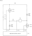
- a circuit diagram of this amplification circuit is shown in FIG. 2 .
- an electromagnet wiring 151 constituting the upper-side radial electromagnet 104 and the like has one end thereof connected to a positive electrode 171a of a power source 171 through a transistor 161 and has the other end connected to a negative electrode 171b of the power source 171 through a current detection circuit 181 and a transistor 162.
- the transistors 161 and 162 are so-called power MOSFET and have a structure in which a diode is connected between a source and a drain thereof.
- the transistor 161 has a cathode terminal 161a of the diode thereof connected to the positive electrode 171a and has an anode terminal 161b connected to one end of the electromagnet wiring 151.
- the transistor 162 has a cathode terminal 162a of the diode thereof connected to the current detection circuit 181 and has an anode terminal 162b connected to the negative electrode 171b.
- a diode 165 for current regeneration has a cathode terminal 165a thereof connected to one end of the electromagnet wiring 151 and has an anode terminal 165b thereof connected to the negative electrode 171b.
- a diode 166 for current regeneration has a cathode terminal 166a thereof connected to the positive electrode 171a and an anode terminal 166b thereof connected to the other end of the electromagnet wiring 151 through the current detection circuit 181.
- the current detection circuit 181 is constituted by a Hall-sensor type current sensor or an electric resistance element, for example.
- the amplification circuit 150 constituted as above corresponds to one electromagnet.
- the similar amplification circuit 150 is constituted for each of the electromagnets, and 10 units of the amplification circuits 150 are connected in parallel to the power source 171.
- an amplification control circuit 191 is constituted by a digital signal processor portion (hereinafter, referred to as a DSP portion), not shown, of the control device 200, for example, and this amplification control circuit 191 is configured to switch on/off the transistors 161 and 162.
- a DSP portion digital signal processor portion
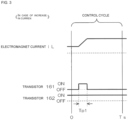
- the amplification control circuit 191 is configured to compare a current value (a signal reflecting this current value is referred to as a current detection signal 191c) detected by the current detection circuit 181 and a predetermined current instructed value. And on the basis of this comparison result, a size of a pulse width (pulse-width time Tp1, Tp2) to be generated in a control cycle Ts, which is one cycle by PWM control, is determined. As a result, gate drive signals 191a and 191b having this pulse width is configured to be output to gate terminals of the transistors 161 and 162 from the amplification control circuit 191.
- a high voltage such as approximately 50V, for example, is used in the power source 171 so that the current flowing through the electromagnet wiring 151 can be rapidly increased (or decreased).
- a capacitor is usually connected between the positive electrode 171a and the negative electrode 171b of the power source 171 for stabilization of the power source 171 (not shown).
- the transistors 161 and 162 when one of the transistors 161 and 162 is turned on, while the other is turned off, a so-called flywheel current is held. And by causing the flywheel current to flow through the amplification circuit 150 as above, a hysteresis loss in the amplification circuit 150 is decreased, and power consumption as the entire circuit can be kept low. Moreover, by controlling the transistors 161 and 162 as above, a high-frequency noise such as a harmonic generated in the turbo-molecular pump 100 can be reduced. Furthermore, by measuring this flywheel current by the current detection circuit 181, the electromagnet current iL flowing through the electromagnet wiring 151 can be detected.
- the transistors 161 and 162 are both turned on only for a period of time corresponding to the pulse-width time Tp1 only once in a control cycle Ts (100 ⁇ s, for example) as shown in FIG. 3 .
- the electromagnet current iL during this period increases toward a current value iLmax (not shown) that can be made to flow from the positive electrode 171a to the negative electrode 171b through the transistors 161 and 162.
- the transistors 161 and 162 are both turned off only for a period of time corresponding to the pulse-width time Tp2 only once in the control cycle Ts as shown in FIG. 4 .
- the electromagnet current iL during this period decreases toward a current value iLmin (not shown) that can be regenerated from the negative electrode 171b to the positive electrode 171a through the diodes 165 and 166.
- an upper side (a side of the inlet port 101) in FIG. 1 is an inlet portion connected to a side of the target device, while a lower side (a side where an exhaust port 15 constituting the outlet port 133 is provided on the base portion 129 so as to protrude to a right side in the figure) is an outlet portion connected to an auxiliary pump (back pump) and the like, not shown.
- the turbo-molecular pump 100 can be used, not only in a perpendicular attitude in a vertical direction as shown in FIG. 1 , but also in an inverted attitude, in a horizontal attitude or even in an inclined attitude.
- turbo-molecular pump 100 the aforementioned outer cylinder 127 and the base portion 129 are combined so as to constitute one case (hereinafter, the both are referred together as a "main-body casing" or the like in some cases).
- the turbo-molecular pump 100 is connected to a box-shaped electric component case (not shown) electrically (and structurally), and the aforementioned control device 200 is incorporated in the electric component case.
- a constitution inside the main-body casing (combination of the outer cylinder 127 and the base portion 129) of the turbo-molecular pump 100 can be divided into a rotation mechanism portion which rotates the rotor shaft 113 and the like by the motor 121 and an exhaust mechanism portion rotated/driven by the rotation mechanism portion.
- the exhaust mechanism portion can be divided into a turbo-molecular pump mechanism portion constituted by the rotor blade 102, the stator blade 123 and the like and a thread-groove pump mechanism portion (Holweck-type exhaust mechanism portion 204) constituted by the rotating-body lower cylinder portion 103b, the threaded spacer 131 and the like.
- the aforementioned purge gas (protective gas) is used for protection for the bearing portion, the rotor blade 102 and the like and performs prevention of erosion caused by the exhaust gas (process gas), cooling of the rotor blade 102 and the like.
- Supply of this purge gas can be made in an ordinary way.
- a purge-gas port 13 extending linearly in a radial direction is provided at a predetermined part of the base portion 129 (a position separated approximately by 180 degrees with respect to the outlet port 133 or the like). And to this purge-gas port 13, the purge gas is supplied from outside the base portion 129 through a purge-gas bomb (N2 gas bomb or the like), a flow regulator (valve device) and the like.
- a purge-gas bomb N2 gas bomb or the like
- a flow regulator valve device
- the aforementioned protective bearing 120 is also called a “touchdown (T/D) bearing", a “backup bearing” and the like.
- FIG. 1 FIGS. 5 to 11 , FIGS. 13 to 15 ) illustrating structures of the turbo-molecular pump 100 and the rotating body 103
- description of hatching indicating a section of a component is omitted in order to avoid cumbersomeness of the figures.
- FIG. 5 and FIG. 6 schematically illustrate the structures of components of the rotating body 103 used in the turbo-molecular pump 100 as described above.
- the rotating body 103 has a structure in which a second component formed by solidifying a powder is caused to cover a periphery of a first component disposed inside.
- the rotating body 103 includes, as shown in FIG. 5 and FIG. 6 , an inner-side cylinder portion 302, an outer-side cylinder portion 304, and blade ring portions 306a to 306k in multiple stages (11 stages, here).
- the inner-side cylinder portion 302 is classified as the first component, while the outer-side cylinder portion 304 and the blade ring portions 306a to 306k are classified as the second components.
- the first component (the inner-side cylinder portion 302, here) is disposed relatively inside, while the second component (the outer-side cylinder portion 304 and the blade ring portions 306a to 306k, here) are disposed on an outer side of the first component.
- the second component is contracted (reduced) and connected to the first component during manufacture of the rotating body 103. Manufacturing methods of the first component and the second component and a manufacturing method of the rotating body 103 will be described later.
- orthogonal coordinates by XYZ axes are illustrated.
- the X axis and the Y axis extend in a horizontal direction
- the Z axis extends in a vertical direction and is orthogonal to the X axis and the Y axis.
- a direction of an arrow in the arrow of each axis indicates a positive direction (positive direction).
- a circle in the coordinates indicates a direction from a depth on the paper toward a front, and a mark with a cross added to a circle indicates a direction from the front on the paper toward the depth.
- the outer-side cylinder portion 304 illustrated in right and left figures in FIG. 6 is classified as the first component and constitutes the rotating-body main body 103a ( FIG. 1 ).
- the inner-side cylinder portion 302 is formed cylindrically with steps.
- An outer diameter of the inner-side cylinder portion 302 is larger as it goes toward one end portion in an axial direction (lower end portion in FIG. 6 ) and smaller in stages as it goes toward the other end portion (upper end portion in FIG. 6 ).
- a first step portion 312, a second step portion 314, and a third step portion 316 are formed in order from the upper end side toward the lower end side.
- Sizes of the first step portion 312, the second step portion 314, and the third step portion 316 are different from one another.
- the sizes of these step portions 312, 314, 316 can be expressed by protruding amounts (extended amounts) in the radial direction of the rotating body 103.
- the first step portion 312 is the largest, and the third step portion 316 is larger than the second step portion 314.
- Protruding directions of the first step portion 312, the second step portion 314, and the third step portion 316 are directions extending in an XY plane in the orthogonal coordinates.
- the inner-side cylinder portion 302 has both ends in a vertical direction (Z-axis direction) open and has a disc portion 318 at a part in the middle of an axis direction. At a center of the disc portion 318, a through hole 320 is provided. Into this through hole 320, an upper end portion of the rotor shaft 113 ( FIG. 1 ) is inserted from below after completion of the rotating body 103.
- the disc portion 318 is disposed at a position substantially similar to that of the first step portion 312 with respect to an axis of the inner-side cylinder portion 302.
- the second step portion 314 is disposed at a position approximately at a middle between the disc portion 318 and the lower end portion of the inner-side cylinder portion 302.
- the third step portion 316 is disposed on the lower end portion of the inner-side cylinder portion 302.
- a part on the upper end side than the first step portion 312 is referred to as a first cylinder portion 322, and a part between the first step portion 312 and the second step portion 314 as a second cylinder portion 324.
- a part between the second step portion 314 and the third step portion 316 is referred to as a third cylinder portion 326.
- a flange portion 328 extending in the radial direction over the entire circumference is formed.
- the outer-side cylinder portion 304 is formed cylindrically with upper and lower end portions (both end portions in the axis direction) open.
- the outer-side cylinder portion 304 is classified as the second component and constitutes the aforementioned rotating-body lower cylinder portion 103b.
- On an upper part in the outer-side cylinder portion 304 a true-circular upper opening 332 is formed, and on a lower part, too, a similar true-circular lower opening 334 is formed.
- a diameter (inner diameter) of the upper opening 332 is smaller than the diameter (inner diameter) of the lower opening 334.
- the outer-side cylinder portion 304 is concentrically combined with the inner-side cylinder portion 302 and is caused to cover the inner-side cylinder portion 302.
- the inner-side cylinder portion 302 enters into the outer-side cylinder portion 304 through the lower opening 334 of the outer-side cylinder portion 304, and as shown in the right figure in FIG. 6 , protrudes upward from the upper opening 332 of the outer-side cylinder portion 304.
- a peripheral edge portion of the upper opening 332 in the outer-side cylinder portion 304 is placed on the flange portion 328 of the inner-side cylinder portion 302, and the flange portion 328 is locked with the peripheral edge portion of the upper opening 332 in the outer-side cylinder portion 304 from below.
- the outer-side cylinder portion 304 constitutes the rotating-body lower cylinder portion 103b ( FIG. 1 ) of the Holweck-type exhaust mechanism portion 204. As shown in FIG. 1 , in the Holweck-type exhaust mechanism portion 204, the rotating-body lower cylinder portion 103b is opposed to the threaded spacer 131 having the rotating-body lower cylinder portion 103b and the thread groove 131a.
- the rotating-body lower cylinder portion 103b is relatively rotated/displaced with respect to the threaded spacer 131 on the outer side of the thread groove 131a.
- the rotating-body lower cylinder portion 103b functions as a kind of a blade. And by means of the rotation of the rotating-body lower cylinder portion 103b, a flow of the exhaust gas along the thread groove 131a is generated, and directivity is given to the exhaust gas.
- the turbo-molecular pump including the Holweck-type exhaust mechanism portion 204 as above is considered such that the second component (the outer-side cylinder portion 304, here) includes a rotor blade for Holweck pump mechanism constituted by a cylinder portion disposed on an outer peripheral surface (constituting the outer peripheral surface).
- the blade ring portions 306a to 306k are components having the rotor blades 102 (102a, 102b, 102c, ).
- a large number of rotor blades 102a to 102k are provided at predetermined angular intervals (10-degree intervals, for example) so as to protrude in the radial direction on an outer peripheral portion of each of cylindrical rotor-blade spacer portions 336a to 336k.
- a shape, a direction and the like of the rotor blades 102a to 102k provided in predetermined number each on each of the blade ring portions 306a to 306k can be similar to those of an ordinary type.
- lengths and inner diameters in the axis direction (Z-axis direction) of the rotor-blade spacer portions 336a to 336k are not uniform, but each is set to an optimal value according to a function and disposition.
- the blade ring portions 306a to 306k are components having rotor blades for turbo-molecular pump mechanism (rotor blades 102) constituted by of blade rows disposed radially. Each of the blade ring portions 306a to 306k can be classified as the rotor blade for turbo-molecular pump mechanism. Moreover, the blade ring portions 306a to 306k as a whole can be classified as the rotor blade for turbo-molecular pump mechanism. Furthermore, the outer-side cylinder portion 304 used integrally with the blade ring portions 306a to 306k can be included and altogether classified as the rotor blade for turbo-molecular pump mechanism.
- the blade ring portions 306a to 306k are concentrically combined with the inner-side cylinder portion 302 as shown in the left figure in FIG. 6 and are caused to cover it from an outer side.
- the inner-side cylinder portion 302 enters into the rotor-blade spacer portions 336a to 336k from below, and the blade ring portions 306a to 306k are stacked concentrically in the axis direction (Z-axis direction).
- the blade ring portions 306a to 306c from the uppermost stage to the third stage are caused to cover the first cylinder portion 322 in the inner-side cylinder portion 302.
- the blade ring portion 306c on the third stage from above is placed on the first step portion 312 in the inner-side cylinder portion 302 and is supported by the first step portion 312.
- the blade ring portion 306b on the second stage is placed on the blade ring portion 306c on the third stage and is supported by the blade ring portion 306c on the third stage.
- the blade ring portion 306a on the first stage is placed on the blade ring portion 306b on the second stage and is supported by the blade ring portion 306b on the second stage.
- the blade ring portions 306d to 306g on the fourth to seventh stages are caused to cover the second cylinder portion 324 in the inner-side cylinder portion 302.
- the blade ring portion 306g on the seventh stage is placed on the second step portion 314 in the inner-side cylinder portion 302.
- the stacked blade ring portions 306d to 306f on the fourth to sixth stages are supported by the blade ring portion 306g on the seventh stage.
- the blade ring portions 306h to 306k on the eighth to eleventh stages are caused to cover the third cylinder portion 326 in the inner-side cylinder portion 302.
- the blade ring portion 306k on the eleventh stage is placed on the peripheral edge portion of the upper opening 332 in the outer-side cylinder portion 304.
- the stacked blade ring portions 306h to 306j on the eighth to tenth stages are supported by the blade ring portion 306k on the eleventh stage.
- the inner-side cylinder portion 302 is classified as the first component, while the outer-side cylinder portion 304 and the blade ring portions 306a to 306k are classified as the second components.
- the second component is contracted and joined to the first component during manufacture of the rotating body 103.
- the inner-side cylinder portion 302 which is the first component, is formed by shaving out a material of solid metal blank (solid columnar material or the like).
- the inner-side cylinder portion 302 is machined equally to a dimension of each part in the rotating body 103 which is a completed product during the shaving-out.
- the inner-side cylinder portion 302 is sintered together with the second component (the outer-side cylinder portion 304 and the blade ring portions 306a to 306k, here) as will be described later, but contraction is not caused by the sintering processing. Even if the contraction is caused, the contraction is drastically smaller than that of the second component.
- the material of which the inner-side cylinder portion 302 is shaved out can be any one of an extruded material manufactured by extrusion, a cast material manufactured by casting, and a forged material manufactured by forging, for example. That is, the inner-side cylinder portion 302 can be any one of the extruded material, the cast material, and the forged material.
- the inner-side cylinder portion 302 can be constituted by a single component or a plurality of components.
- the inner-side cylinder portion 302 can be formed of at least any one of the extruded material, the cast material, and the forged material.
- the inner-side cylinder portion 302 can be constituted by combining these materials.
- the inner-side cylinder portion 302 which is the first component, can be also manufactured by other manufacturing methods.
- the inner-side cylinder portion 302 can be manufactured by laminate shaping using a 3D printer. The method of manufacturing the inner-side cylinder portion 302 by the 3D printer will be described later as another embodiment ( FIG. 14 and FIG. 15 ).
- the inner-side cylinder portion 302 can be manufactured by powder metallurgy and sintered in advance. In this case, too, no contraction is caused when being sintered together with the second component (the outer-side cylinder portion 304 and the blade ring portions 306a to 306k, here).
- the outer-side cylinder portion 304 and the blade ring portions 306a to 306k which are the second components, are formed of a green pellet.
- the green pellet is constituted by a metal powder (powders of an aluminum alloy, a stainless steel and the like) pressurized and solidified by press-molding.
- the manufacture of the outer-side cylinder portion 304 and the blade ring portions 306a to 306k can be also performed by the laminate shaping using the 3D printer (3D shaping device).
- a PBF (Powder Bed Fusion) method As methods of the laminate shaping by the 3D printer, a PBF (Powder Bed Fusion) method, the BJ (Binder Jetting) method, a DED (Directed Energy Deposition) method, the FDM (Fused Deposition Modeling) method and the like are known, for example.
- the PBF method and the DED method are classified as methods not requiring the sintering processing after lamination, while the BJ method and the FDM method are classified as methods requiring the sintering processing after lamination.
- the manufacture of the outer-side cylinder portion 304 and the blade ring portions 306a to 306k can be performed by the stereoscopic shaping device using the method requiring the sintering processing such as the BJ method or the FDM method.
- the manufacture of the outer-side cylinder portion 304 and the blade ring portions 306a to 306k by the laminate shaping using the 3D printer, wasting of the materials can be prevented as compared with a case where the shaving-out is employed.
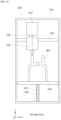
- Outlines of the BJ method and the FDM method will be described below.
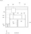
- a head portion 230 selectively injects a liquid binding agent (Binder) 250 from an inkjet nozzle (not shown) and solidifies layers of a material powder 238 one by one.
- a material supply portion 224, a laminating portion 226, an excess-material receiving portion 228, and the head portion 230 are provided in a housing 222 of a stereoscopic shaping device 220.
- the material supply portion 224, the laminating portion 226, and the excess-material receiving portion 228 are aligned in one direction (left to right in FIG. 8 , the X-axis direction).
- the material supply portion 224 includes a supply elevator 232 and a roller (also called a "recoater") 234.
- the supply elevator 232 moves upward (a positive direction of the Z axis in an XYZ coordinates in FIG. 8 ) by using a threaded portion 236 and pushes up the whole material powder 238.
- a movement amount (rising amount) of the supply elevator 232 is approximately several tens microns per session of movement, for example.
- the roller 234 rotates, scrapes up the pushed-up material powder 238 and moves it toward the laminating portion 226.
- the laminating portion 226 includes a laminating elevator 240.
- the laminating portion 226 displaces a laminating table 244 of the laminating elevator 240 downward (a negative direction of the Z axis) by a predetermined amount per session of lamination by using a threaded portion 242.
- the displacement amount per session of the laminating table 244 corresponds to a shaping thickness (lamination thickness) in one session of the lamination.
- the material powder 238 is supplied by the roller 234, and the material powder 238 is laid.
- the head portion 230 moves at a high speed and is positioned by a positioning mechanism portion 248.
- the positioning mechanism portion 248 includes displacement mechanisms in the X-axis direction and the Y-axis direction.
- the positioning mechanism portion 248 may include a displacement mechanism of the Z axis.
- the head portion 230 selectively injects the binding agent 250 from the inkjet nozzle while moving on the basis of data on each layer of an object to be shaped (the outer-side cylinder portion 304, here) as a shaping target.
- the laminating table 244 is lowered by one stage, and the roller 234 lays the new material powder 238.
- the binding agent 250 is injected in conformity with a sectional shape of the outer-side cylinder portion 304. Until the shaping of the outer-side cylinder portion 304 is completed, laying of the material powder 238 and formation of each layer are repeated.
- the object to be shaped is taken out and assembled as shown in the left figure in FIG. 6 and then, sintering of the shaped object as shown in the right figure in FIG. 6 is performed.
- the sintering is performed in order to improve mechanical characteristics of the material powder 238 bound by the binding agent 250.
- the binding material in the object to be shaped is burned out, the shaped object is somewhat contracted, and required mechanical characteristics are obtained.
- a stereoscopic shaping device 260 includes a filament supply portion 262 and a head portion 264.
- a filament supply portion 262 includes a filament supply portion 262 and a head portion 264.
- the head portion 264 is mounted on the positioning mechanism portion 248 and moves in accordance with a sectional shape of the object to be shaped (the outer-side cylinder portion 304, here).
- the stereoscopic shaping device 260 by the FDM method ( FIG. 9 ) leads out a filament 266 containing the binding agent from the filament supply portion 262.
- the stereoscopic shaping device 260 pushes out the filament 266 from the head portion 264 while fusing it by a heat of a heat source and performs stereoscopic shaping by laminating each layer on the laminating table 244.
- the outer-side cylinder portion 304 and the blade ring portions 306a to 306k (second component) are formed by the green pellet, these components are assembled to the inner-side cylinder portion 302 (first component) as shown in the left figure in FIG. 6 .
- the outer-side cylinder portion 304 and the blade ring portions 306a to 306k are caused to concentrically cover the inner-side cylinder portion 302.
- the inner-side cylinder portion 302 and the outer-side cylinder portion 304 and the blade ring portions 306a to 306k caused to cover the inner-side cylinder portion 302 are subjected to the sintering processing altogether.
- the supporting tool 400 is formed having a stepped columnar shape.
- FIG. 7 illustrates a state of the outer-side cylinder portion 304, and the blade ring portions 306a to 306k after the sintering processing (after contraction).
- the supporting tool 400 is used also during the sintering processing, but contraction as in the outer-side cylinder portion 304 is not caused, and dimensions before and after the sintering processing is hardly changed.
- the supporting tool 400 will be described by applying FIG. 7 .
- An outer diameter of the supporting tool 400 is larger on a one-end portion in the axis direction (lower end portion in FIG. 7 ) and becomes smaller in steps as it goes toward the other-end portion (upper end portion in FIG. 7 ).
- a first step portion 412 and a second step portion 414 are formed in order from an upper end side toward a lower end side. In the example in FIG. 7 , sizes of the first step portion 412 and the second step portion 414 are equal to each other.
- An upper end portion of the supporting tool 400 is a first columnar portion 416 having a relatively smaller diameter, and a portion on a lower side of the first columnar portion 416 is a second columnar portion 418 having a diameter larger than that of the first columnar portion 416.
- a flange portion 420 extends in the radial direction over the entire circumference.
- the inner-side cylinder portion 302 When the inner-side cylinder portion 302 is to be covered with the outer-side cylinder portion 304, first, the inner-side cylinder portion 302 is caused to cover the first columnar portion 416 in the supporting tool 400 from above.
- the flange portion 328 of the inner-side cylinder portion 302 is caused to cover the first step portion 412 in the supporting tool 400 and is placed on the second columnar portion 418.
- the flange portion 328 of the inner-side cylinder portion 302 contacts the second columnar portion 418 from above.
- An inner diameter of the third cylinder portion 326 in the inner-side cylinder portion 302 is formed somewhat larger than the diameter of the first columnar portion 416 in the supporting tool 400. Thus, a clearance 430 is generated between the third cylinder portion 326 in the inner-side cylinder portion 302 and the first columnar portion 416 in the supporting tool 400.
- a position of the outer-side cylinder portion 304 in the axis direction (Z-axis direction) is regulated by the flange portion 328 of the inner-side cylinder portion 302.
- the outer-side cylinder portion 304 and the blade ring portions 306a to 306k contract by approximately 20% in a state supported by the supporting tool 400.
- the inner-side cylinder portion 302 is formed by the method of shaving-out and the like so that it does not contract during the sintering processing.
- the outer-side cylinder portion 304 and the blade ring portions 306a to 306k caused to cover the inner-side cylinder portion 302 are contracted and brought into close contact with the inner-side cylinder portion 302.
- the clearance between the inner-side cylinder portion 302 and the outer-side cylinder portion 304 as well as the blade ring portions 306a to 306k disappears.
- the inner-side cylinder portion 302, the outer-side cylinder portion 304, and the blade ring portions 306a to 306k are fused and joined.
- a size of the clearance between the inner-side cylinder portion 302 and the outer-side cylinder portion 304 as well as the blade ring portions 306a to 306k before the sintering is determined so that the clearance from the inner-side cylinder portion 302 disappears, and joining between the components is generated by contraction of the outer-side cylinder portion 304 and the blade ring portions 306a to 306k.
- the outer-side cylinder portion 304 and the blade ring portions 306a to 306k are not separated from the inner-side cylinder portion 302.
- the rotating body 103 manufactured as above can be considered to be such that the inner-side cylinder portion 302 and the outer-side cylinder portion 304 as well as the blade ring portions 306a to 306k are clearance fit before the sintering processing and are interference fit after the sintering processing. And according to the manufacturing method as above, after an outer-side component is caused to cover an inner-side component, there is no need to perform a work of press-fit, shrink-fit, welding, brazing or the like. Therefore, a work to assemble the outer-side cylinder portion 304 as well as the blade ring portions 306a to 306k to the inner-side cylinder portion 302 is easy and moreover, damage on a material of the component is small.
- sintering processing is not limited to completion in one session but may be performed in plural times, for example (twice or three times).
- the outer-side cylinder portion 304 and the blade ring portions 306a to 306k which are components obtained by solidifying the metal powder contract by approximately 20% in the sintering process.
- components located relatively on the outer side in the radial direction with the axis of the rotating body 103 as a reference are susceptible to a centrifugal force largely as compared with components located on the inner side, and deformation can occur easily during rotation.
- measures can be taken for the component which contracted by sintering so that loosening by the centrifugal force during the rotation does not occur.
- component dimensions before the sintering can be set so that a clearance (reference dimension of the clearance) between a component on an inner side (shaft side) and a component on an outer side (hole side) satisfies the following relationship;
- Reference dimension of clearance a ⁇ c ⁇ b ⁇ d + e / 2
- a is as follows.
- parameters b to e are set as follows:
- the inner diameter of the outer-side component (the blade ring portions 306a to 306k, for example) is set to 118.75 ⁇ 0.1 mm, and each component is designed by using this value as a reference.
- contraction of approximately 20% is generated in the second component, and it is effective to devise measures assuming the contraction in advance.
- the supporting tool 400 as shown in FIG. 7 , even if the outer-side cylinder portion 304 and the blade ring portions 306a to 306 are contracted during the sintering process, a locked state of the inner-side cylinder portion 302, the outer-side cylinder portion 304, and the blade ring portions 306a to 306 can be ensured, and separation of these components from one another can be prevented.
- the pressing force (arrow A) can be transmitted to the blade ring portions 306d to 306g on the fourth to seventh stages.
- the blade ring portions 306d to 306g on the fourth to seventh stages are pressed onto the second step portion 314 of the inner-side cylinder portion 302, and loosening of the blade ring portions 306d to 306g with respect to the inner-side cylinder portion 302 is prevented.
- the pressing force can be transmitted to the blade ring portions 306h to 306k on the eighth to eleventh stages and the outer-side cylinder portion 304.
- the blade ring portions 306h to 306k on the eighth to eleventh stages and the outer-side cylinder portion 304 are pressed onto the third step portion 316 of the inner-side cylinder portion 302, and loosening of the blade ring portions 306h to 306k and the outer-side cylinder portion 304 with respect to the inner-side cylinder portion 302 is prevented.
- FIG. 7 illustrates the state of the outer-side cylinder portion 304 and the blade ring portions 306a to 306k after the contraction as described above.
- the outer-side cylinder portion 304 and the blade ring portions 306a to 306k are joined to the inner-side cylinder portion 302, and a clearance 432 is generated between the lower end portion of the outer-side cylinder portion 304 and the flange portion 420 of the supporting tool 400.
- the first step portion 312 to the third step portion 316 become positioning spots, respectively.
- an influence of a shift by the contraction in the vertical direction can be suppressed as much as possible.
- a contraction rate during sintering is changed by a filling rate of a metal powder (a rate of containing the metal powder).
- a filling rate of a metal powder a rate of containing the metal powder.
- a clearance can be generated between the blade ring portion 306c on the third stage and the blade ring portion 306d on the fourth stage or between the blade ring portion 306g on the seventh stage and the blade ring portion 306h on the eighth stage by contraction, but a force of pressing downward may be generated by interposing an elastic body (spring element) such as a spring washer or the like in a part of the clearance.
- spring element such as a spring washer
- the pressing force indicated by the arrow A is applied at two spots, but the pressing force may be applied annularly over the entire circumference of the rotor-blade spacer portion 336a in the blade ring portion 306a on the first stage, for example. Moreover, the pressing force may be applied in an arc state and partially (or intermittently) to the rotor-blade spacer portion 336a. Furthermore, the application of the pressing force can be performed through various elastic bodies (spring elements) such as a spring washer, a coil spring, a plate spring and the like, for example.
- spring elements such as a spring washer, a coil spring, a plate spring and the like, for example.
- Components that can be the second components are not limited to the rotor blade for turbo-molecular pump mechanism or the rotor blade for Holweck-type pump mechanism (the outer-side cylinder portion 304 constituting the rotating-body lower cylinder portion 103b ( FIG. 1 )) as described above.
- the turbo-molecular pump 100 includes a Siegbahn-type exhaust mechanism portion 202 in some cases.
- the rotor blade for Siegbahn-type pump mechanism (rotor-disc ring portions 370a to 370c shown in FIG. 13 ) constituting the Siegbahn-type exhaust mechanism portion 202 can also be the second component.
- the Siegbahn-type exhaust mechanism portion 202 is included in combination with the Holweck-type exhaust mechanism portion 204 in some cases. Moreover, though not shown, the Siegbahn-type exhaust mechanism portion 202 is provided singularly without accompanying the Holweck-type exhaust mechanism portion 204 in some cases. By including the Siegbahn-type exhaust mechanism portion 202, the directionality is given to the exhausted gas, and exhaust performances of the turbo-molecular pump 100 is improved.
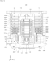
- FIG. 10 illustrates an example of a structure in which the turbo-molecular pump 100 includes both the Siegbahn-type exhaust mechanism portion 202 and the Holweck-type exhaust mechanism portion 204.
- the structure of the Siegbahn-type exhaust mechanism portion 202 and a relationship between the Siegbahn-type exhaust mechanism portion 202 and the Holweck-type exhaust mechanism portion 204 will be described, but portions similar to those in the turbo-molecular pump 100 shown in FIG. 1 are given the same signs and the explanation thereof is omitted as appropriate.
- the Siegbahn-type exhaust mechanism portion 202 is formed so as to spatially continue to a subsequent stage of (on a downstream side immediately after) the turbo-molecular pump mechanism portion constituted by the aforementioned rotor blades 102 (102a, 102b, 102c, ... each having a blade row) and the stator blades 123 (123a, 123b, 123c, ...) and the like.
- the Holweck-type exhaust mechanism portion 204 is formed so as to spatially continue to a subsequent stage of (on the downstream side immediately after) the Siegbahn-type exhaust mechanism portion 202.
- the Siegbahn-type exhaust mechanism portion 202 is a Siegbahn-type exhaust mechanism and has stator discs 349a and 349b and rotor discs 350a to 350c.
- the rotor-disc ring portions 370a to 370c ( FIG. 13 , which will be described later) on which the rotor discs 350a to 350c are provided function as a rotor blade for Siegbahn-type pump mechanism constituted by disc portions disposed on an outer peripheral surface.
- the rotor discs 350a to 350c are disposed continuing to a lower stage of the rotor blade 102 and are aligned in the axis direction.
- the rotor discs 350a to 350c are formed integrally with the rotating body 103 and are rotated in the same direction as those of the rotor shaft 113 and the rotating body 103 with the rotation of the rotating body 103. That is, the rotor discs 350a to 350c are rotated integrally also with the rotor blades 102 (102a, 102b, 102c ).
- a large number of ridge portions 351 each having a rectangular sectional shape are formed so as to protrude.
- a Siegbahn spiral groove portion 352 which is a spiral groove channel, is formed.
- FIG. 11 illustrates, in an enlarged manner, a groove exhaust mechanism portion in a portion on the right side (in a two-dot chain line frame L) of the rotor shaft 113 shown in FIG. 10 .
- the groove exhaust mechanism portion has a structure of line symmetry (symmetry in FIG. 10 ) with the axes of the main-body casing (combination of the outer cylinder 127 and the base portion 129), the rotor shaft 113 and the like as a center and thus, only the portion on the right side in FIG. 10 is illustrated in the enlarged manner, here, while a portion on the left side is not shown.
- the rotor discs 350a to 350c are rotated. And relative rotational displacement is performed between each of the stator discs 349a and 349b and each of the rotor discs 350a to 350c. Moreover, as shown by a large number of arrows Q (only some of them are given signs) in FIGS. 10 to 12 , the gas transferred by the turbo-molecular pump mechanism portion (constituted by the rotor blade 102, the stator blade 123 and the like) reaches the Siegbahn-type exhaust mechanism portion 202 of the groove exhaust mechanism portion.
- the gas which has reached the Siegbahn-type exhaust mechanism portion 202 flows into the Siegbahn spiral groove portion 352 on the uppermost stream and passes through a channel which is gradually narrowed in a depth direction (axial direction of the rotor shaft 113). After that, the gas goes to a centripetal direction (axis direction) or a centrifugal direction via turnback portions 354 and 356 and the Siegbahn spiral groove portion 352 at a certain depth and flows into the Holweck-type exhaust mechanism portion 204 which will be described later.
- the rotor discs 350a to 350c are disposed in line in the axial direction with respect to the rotor blade 102. Therefore, a structure to be assembled to the inner-side cylinder portion 302 can be realized similarly to the blade ring portions 306a to 306k ( FIG. 6 ).
- the rotor-disc ring portions 370a to 370c are formed separately of a green pellet made by solidifying and coagulating a metal powder.
- the rotor-disc ring portions 370a to 370c have rotor-disc spacer portions 372a to 372c similar to the rotor-blade spacer portions 336a to 336k ( FIG. 6 ) of the blade ring portions 306a to 306k.
- the rotor discs 350a to 350c protrude from the rotor disc spacer portions 372a to 372c in a flange state in the radial direction.
- Manufacture of the rotor-disc ring portions 370a to 370c can be performed by the laminate shaping using the 3D printer.
- the laminate shaping by the 3D printer similarly to the blade ring portions 306a to 306k, the BJ method or the FDM method or the like requiring the sintering processing is employed, for example.
- the rotor-disc ring portions 370a to 370c are supposed to be formed by the stereoscopic shaping devices 220 and 260 using the BJ method or the FDM method.
- the rotor-disc ring portions 370a to 370c are caused to cover the inner-side cylinder portion 302 in order from the outer side in the clearance fit state.
- the rotor-disc ring portions 370a to 370c are subjected to the sintering processing together with the inner-side cylinder portion 302, the outer-side cylinder portion 304, and the blade ring portions 306a to 306k and integrated with the inner-side cylinder portion 302.
- a clearance between inner peripheral portions of the rotor-disc ring portions 370a to 370c and the inner-side cylinder portion 302 before the sintering processing can be set similarly to that of the blade ring portions 306a to 306k.
- a component having the rotor discs 350a to 350c (the rotor-disc ring portions 370a to 370c functioning as the rotor blades for Siegbahn-type pump mechanism, here) can be formed not by shaving-out. And generation of chips can be prevented, and wasting of the materials and labor for recycling in relation with wastes can be reduced as compared with formation by shaving-out.
- the rotor blade for Siegbahn-type pump mechanism (the rotor-disc ring portions 370a to 370c, here) can be easily assembled to the inner-side cylinder portion 302 and moreover, damage on a material of the component is small. And strict centering is not needed at the assembling work, whereby the assembling work is also made easy.
- a Holweck-type exhaust channel 360 receives the gas having passed through a Siegbahn-type exhaust channel 366. And the Holweck-type exhaust channel 360 leads it from the outer peripheral side to the inner peripheral side by the Holweck-type spiral groove portion 362 which receives it and introduces it to the thread groove 131a via the turnback portion. Moreover, in the thread groove 131a, the introduced gas is led to the downstream side along the thread groove 131a with the rotation of the rotating body 103.
- the Holweck-type exhaust mechanism portion 204 in the examples in FIGS. 10 to 12 is configured to perform transfer of the gas to the radial direction with the axis of the rotor shaft 113 as the reference and the transfer of the gas to the axis direction of the rotor shaft 113.
- a portion which performs transfer of the gas to the radial direction can be classified so as to be included in the Siegbahn-type exhaust mechanism portion 202, and only a portion which performs the transfer of the gas to the axis direction of the rotor shaft 113 can be classified as the Holweck-type exhaust mechanism portion 204.
- the inner-side cylinder portion 302 which is the first component, was formed by shaving out the material of solid metal blank (columnar material or the like).
- the inner-side cylinder portion 302 is manufactured by laminate shaping using the 3D printer.
- the PBF method or the DED method can be used for the manufacture of the inner-side cylinder portion 302.
- the PBF method and the DED method are classified as methods not requiring the sintering processing after lamination.
- the 3D printer stereographic shaping device
- wasting of the material can be prevented as compared with the case where the shaving-out is employed.
- an outline of the PBF method or the DED method will be described. Note that the portions similar to those in the BJ method shown in FIG. 8 and in the FDM method shown in FIG. 9 are given the same signs, and explanation is omitted as appropriate.
- the material powder 238 laid flat is laminated while being fused and fixed for each layer by a heat source (a laser, an electronic beam or the like) output from the head portion 272.
- a heat source a laser, an electronic beam or the like
- the laser is used as the heat source.
- the head portion 272 emits a laser beam 274 from a laser light source via an incorporated optical system (not shown).
- irradiation of the laser beam 274 (laser irradiation) is performed with a predetermined beam diameter toward the material powder 238 immediately below (negative direction of the Z axis).
- the material powder 238 is fused and solidified.
- An irradiation shape of the laser beam 274 (a shape of a movement locus of the laser beam 274) is determined on the basis of data of each layer obtained by slicing 3D model data of the inner-side cylinder portion 302.
- an inactive gas such as argon (Ar), for example, may be filled in a region where the shaping is performed (shaping region) so as to lower oxygen concentration and to prevent oxidization of the material powder 238.
- a plurality of the head portions 272 may be mounted in order to improve productivity.
- the metal powder (material powder) or metal of a filament is fused and build-up welded by a directional energy beam such as a laser, an electronic beam, a plasma arc and the like.
- a directional energy beam such as a laser, an electronic beam, a plasma arc and the like.
- a stereoscopic shaping device 280 includes a filament supply portion 282 and a head portion 284.
- the head portion 284 is mounted on the positioning mechanism portion 248 and moves in accordance with a profile shape of an object to be shaped (the inner-side cylinder portion 302, here).
- the head portion 284 emits the laser beam (not shown).
- the filament 286 is fused and coagulated, and each layer of the inner-side cylinder portion 302 is laminated.
- the inner-side cylinder portion 302 may be the first component by being sintered after being formed by the stereoscopic shaping device using the BJ method or the FDM method.
- the second component the outer-side cylinder portion 304 and the blade ring portions 306a to 306k, here
- the first component the inner-side cylinder portion 302, here
- the 3D printer which executes the BJ method or the FDM method, and the 3D printer of the other methods (the PBF method, the DED method or the like) does not have to be used when manufacturing the first component.
- a vacuum pump (the turbo-molecular pump 100 and the like) according to this application has the following characteristics.
Landscapes
- Engineering & Computer Science (AREA)
- Manufacturing & Machinery (AREA)
- Chemical & Material Sciences (AREA)
- Materials Engineering (AREA)
- Mechanical Engineering (AREA)
- General Engineering & Computer Science (AREA)
- Composite Materials (AREA)
- Physics & Mathematics (AREA)
- Plasma & Fusion (AREA)
- Non-Positive Displacement Air Blowers (AREA)
- Powder Metallurgy (AREA)
Applications Claiming Priority (2)
| Application Number | Priority Date | Filing Date | Title |
|---|---|---|---|
| JP2022003614A JP7390408B2 (ja) | 2022-01-13 | 2022-01-13 | 真空ポンプ、真空ポンプ用回転体、及び真空ポンプの製造方法 |
| PCT/JP2023/000442 WO2023136262A1 (ja) | 2022-01-13 | 2023-01-11 | 真空ポンプ、真空ポンプ用回転体、及び真空ポンプの製造方法 |
Publications (2)
| Publication Number | Publication Date |
|---|---|
| EP4464899A1 true EP4464899A1 (de) | 2024-11-20 |
| EP4464899A4 EP4464899A4 (de) | 2025-12-24 |
Family
ID=81943840
Family Applications (1)
| Application Number | Title | Priority Date | Filing Date |
|---|---|---|---|
| EP23740271.4A Pending EP4464899A4 (de) | 2022-01-13 | 2023-01-11 | Vakuumpumpe, drehkörper für vakuumpumpe und verfahren zur herstellung einer vakuumpumpe |
Country Status (8)
| Country | Link |
|---|---|
| US (1) | US20250043790A1 (de) |
| EP (1) | EP4464899A4 (de) |
| JP (1) | JP7390408B2 (de) |
| KR (1) | KR20240136312A (de) |
| CN (1) | CN118434974A (de) |
| GB (1) | GB202206259D0 (de) |
| IL (1) | IL313557A (de) |
| WO (1) | WO2023136262A1 (de) |
Families Citing this family (1)
| Publication number | Priority date | Publication date | Assignee | Title |
|---|---|---|---|---|
| JP2024165740A (ja) * | 2023-05-18 | 2024-11-28 | 株式会社島津製作所 | 真空ポンプのロータ翼の製造方法、真空ポンプのロータ翼、真空ポンプ |
Family Cites Families (7)
| Publication number | Priority date | Publication date | Assignee | Title |
|---|---|---|---|---|
| JPS6284519U (de) | 1985-11-19 | 1987-05-29 | ||
| JPS62203721A (ja) * | 1986-03-03 | 1987-09-08 | Inoue Japax Res Inc | タ−ボポンプ |
| ITTO20020770A1 (it) | 2002-09-06 | 2004-03-07 | Varian Spa | Metod0 per fabbricare rotori di pompe da vuoto e prodotti |
| JP2007071139A (ja) | 2005-09-08 | 2007-03-22 | Osaka Vacuum Ltd | 複合真空ポンプのロータ |
| EP3034880B1 (de) | 2014-12-15 | 2019-10-16 | Pfeiffer Vacuum Gmbh | Rotoranordnung für eine vakuumpumpe und verfahren zur herstellung derselben |
| EP3085964B1 (de) | 2015-04-21 | 2019-12-11 | Pfeiffer Vacuum Gmbh | Herstellung eines vakuumpumpen-teils mittels eines metallischen, generativen fertigungsverfahrens |
| JP7192660B2 (ja) * | 2019-05-30 | 2022-12-20 | 株式会社島津製作所 | 真空ポンプおよびリークディテクタ |
-
2022
- 2022-01-13 JP JP2022003614A patent/JP7390408B2/ja active Active
- 2022-04-29 GB GBGB2206259.0A patent/GB202206259D0/en not_active Ceased
-
2023
- 2023-01-11 US US18/719,616 patent/US20250043790A1/en not_active Abandoned
- 2023-01-11 EP EP23740271.4A patent/EP4464899A4/de active Pending
- 2023-01-11 IL IL313557A patent/IL313557A/en unknown
- 2023-01-11 CN CN202380015247.8A patent/CN118434974A/zh active Pending
- 2023-01-11 KR KR1020247016665A patent/KR20240136312A/ko active Pending
- 2023-01-11 WO PCT/JP2023/000442 patent/WO2023136262A1/ja not_active Ceased
Also Published As
| Publication number | Publication date |
|---|---|
| IL313557A (en) | 2024-08-01 |
| CN118434974A (zh) | 2024-08-02 |
| US20250043790A1 (en) | 2025-02-06 |
| EP4464899A4 (de) | 2025-12-24 |
| GB202206259D0 (en) | 2022-06-15 |
| KR20240136312A (ko) | 2024-09-13 |
| JP2023102884A (ja) | 2023-07-26 |
| WO2023136262A1 (ja) | 2023-07-20 |
| JP7390408B2 (ja) | 2023-12-01 |
Similar Documents
| Publication | Publication Date | Title |
|---|---|---|
| EP4464899A1 (de) | Vakuumpumpe, drehkörper für vakuumpumpe und verfahren zur herstellung einer vakuumpumpe | |
| EP4184013A1 (de) | Vakuumpumpe und reinigungssystem für eine vakuumpumpe | |
| CN103801799A (zh) | 制造回转件的方法及用该方法制造的回转件 | |
| EP4212729A1 (de) | Vakuumpumpe | |
| EP4163498A1 (de) | Vakuumpumpe und vakuumpumpen-drehkörper | |
| JP7600712B2 (ja) | モータ | |
| JP2023084457A (ja) | 真空ポンプ、真空ポンプ構成部品、及び、真空ポンプの製造方法 | |
| WO2022030373A1 (ja) | 真空排気系の洗浄装置 | |
| CN116670398A (zh) | 真空泵、旋转体、罩部及旋转体的制造方法 | |
| WO2025191419A1 (en) | Vacuum pump and vacuum pump component | |
| WO2020237467A1 (zh) | 电机及其转子元件、转子元件的制造方法 | |
| EP4579088A1 (de) | Vakuumpumpe und festbauteil | |
| EP4194699A1 (de) | Vakuumpumpe und rotorblatt für eine vakuumpumpe | |
| WO2025169780A1 (ja) | 真空ポンプ、及び真空ポンプ構成部品 | |
| US12404861B2 (en) | Vacuum pump and rotating body for vacuum pump | |
| JP2022094272A (ja) | 真空ポンプ | |
| JP7608923B2 (ja) | モータ | |
| JP7855019B2 (ja) | 真空ポンプ | |
| JP7598396B2 (ja) | 真空ポンプ | |
| WO2022163341A1 (ja) | 真空ポンプ及びスペーサ | |
| US12188477B2 (en) | Vacuum pump and rotating cylinder provided in vacuum pump | |
| JP2026054169A (ja) | 真空ポンプ、ハーメチックコネクタ、及びハーメチックコネクタの製造方法 | |
| WO2020241522A1 (ja) | 真空ポンプ及び該真空ポンプに備えられた保護部 | |
| JP2025117615A (ja) | 真空ポンプ、及び磁気軸受装置 | |
| JP2023017160A (ja) | 真空ポンプ |
Legal Events
| Date | Code | Title | Description |
|---|---|---|---|
| STAA | Information on the status of an ep patent application or granted ep patent |
Free format text: STATUS: THE INTERNATIONAL PUBLICATION HAS BEEN MADE |
|
| PUAI | Public reference made under article 153(3) epc to a published international application that has entered the european phase |
Free format text: ORIGINAL CODE: 0009012 |
|
| STAA | Information on the status of an ep patent application or granted ep patent |
Free format text: STATUS: REQUEST FOR EXAMINATION WAS MADE |
|
| 17P | Request for examination filed |
Effective date: 20240607 |
|
| AK | Designated contracting states |
Kind code of ref document: A1 Designated state(s): AL AT BE BG CH CY CZ DE DK EE ES FI FR GB GR HR HU IE IS IT LI LT LU LV MC ME MK MT NL NO PL PT RO RS SE SI SK SM TR |
|
| DAV | Request for validation of the european patent (deleted) | ||
| DAX | Request for extension of the european patent (deleted) | ||
| A4 | Supplementary search report drawn up and despatched |
Effective date: 20251124 |
|
| RIC1 | Information provided on ipc code assigned before grant |
Ipc: B22F 7/06 20060101ALI20251118BHEP Ipc: F04D 19/04 20060101AFI20251118BHEP Ipc: B22F 7/08 20060101ALI20251118BHEP Ipc: B22F 10/14 20210101ALI20251118BHEP Ipc: B22F 10/18 20210101ALI20251118BHEP Ipc: B22F 10/25 20210101ALI20251118BHEP Ipc: B22F 10/28 20210101ALI20251118BHEP Ipc: B33Y 10/00 20150101ALI20251118BHEP Ipc: B33Y 80/00 20150101ALI20251118BHEP Ipc: B22F 5/10 20060101ALI20251118BHEP Ipc: F04D 29/02 20060101ALI20251118BHEP Ipc: F04D 29/32 20060101ALI20251118BHEP Ipc: B22F 5/00 20060101ALI20251118BHEP |