EP4464857A2 - Paneel zur herstellung eines lose verlegten bodenbelags - Google Patents
Paneel zur herstellung eines lose verlegten bodenbelags Download PDFInfo
- Publication number
- EP4464857A2 EP4464857A2 EP24205296.7A EP24205296A EP4464857A2 EP 4464857 A2 EP4464857 A2 EP 4464857A2 EP 24205296 A EP24205296 A EP 24205296A EP 4464857 A2 EP4464857 A2 EP 4464857A2
- Authority
- EP
- European Patent Office
- Prior art keywords
- panel
- coupling means
- male
- female
- tenon
- Prior art date
- Legal status (The legal status is an assumption and is not a legal conclusion. Google has not performed a legal analysis and makes no representation as to the accuracy of the status listed.)
- Pending
Links
Images

Classifications
-
- E—FIXED CONSTRUCTIONS
- E04—BUILDING
- E04F—FINISHING WORK ON BUILDINGS, e.g. STAIRS, FLOORS
- E04F15/00—Flooring
- E04F15/02—Flooring or floor layers composed of a number of similar elements
- E04F15/02038—Flooring or floor layers composed of a number of similar elements characterised by tongue and groove connections between neighbouring flooring elements
-
- E—FIXED CONSTRUCTIONS
- E04—BUILDING
- E04F—FINISHING WORK ON BUILDINGS, e.g. STAIRS, FLOORS
- E04F2201/00—Joining sheets or plates or panels
- E04F2201/01—Joining sheets, plates or panels with edges in abutting relationship
- E04F2201/0138—Joining sheets, plates or panels with edges in abutting relationship by moving the sheets, plates or panels perpendicular to the main plane
-
- E—FIXED CONSTRUCTIONS
- E04—BUILDING
- E04F—FINISHING WORK ON BUILDINGS, e.g. STAIRS, FLOORS
- E04F2201/00—Joining sheets or plates or panels
- E04F2201/01—Joining sheets, plates or panels with edges in abutting relationship
- E04F2201/0153—Joining sheets, plates or panels with edges in abutting relationship by rotating the sheets, plates or panels around an axis which is parallel to the abutting edges, possibly combined with a sliding movement
-
- E—FIXED CONSTRUCTIONS
- E04—BUILDING
- E04F—FINISHING WORK ON BUILDINGS, e.g. STAIRS, FLOORS
- E04F2201/00—Joining sheets or plates or panels
- E04F2201/02—Non-undercut connections, e.g. tongue and groove connections
- E04F2201/023—Non-undercut connections, e.g. tongue and groove connections with a continuous tongue or groove
-
- E—FIXED CONSTRUCTIONS
- E04—BUILDING
- E04F—FINISHING WORK ON BUILDINGS, e.g. STAIRS, FLOORS
- E04F2201/00—Joining sheets or plates or panels
- E04F2201/04—Other details of tongues or grooves
- E04F2201/042—Other details of tongues or grooves with grooves positioned on the rear-side of the panel
-
- E—FIXED CONSTRUCTIONS
- E04—BUILDING
- E04F—FINISHING WORK ON BUILDINGS, e.g. STAIRS, FLOORS
- E04F2201/00—Joining sheets or plates or panels
- E04F2201/04—Other details of tongues or grooves
- E04F2201/043—Other details of tongues or grooves with tongues and grooves being formed by projecting or recessed parts of the panel layers
Definitions
- the present invention relates to the field of loose-lay floor coverings, and more particularly concerns a panel, preferably made of polyvinyl chloride, having the shape of a strip or slab for producing such a covering, the assembly of which is carried out according to an inclined kinematic on a first edge, and vertical on a second adjacent edge.
- This type of panel is illustrated for example by the document EP 3 105 392 , and the document US 2013/0309441 . Both of these documents describe a panel having first and second complementary male/female coupling means on opposite pairs of sides for joining like panels together to form a floor covering.
- the coupling means on the short sides have complementary means for resisting vertical disassembly, and external walls inclined relative to a vertical plane and oriented towards the inside of the panel. Assembly is achieved by tilting the panels along a long side and locking them vertically on a short side.
- the installer When installing this type of floor covering, the installer first assembles the long side in an inclined assembly direction, for example at an angle of between 10° and 50° and, while maintaining the angle of inclination of the panel, he then slides it laterally towards the previous panel until it comes to a stop.
- One of the aims of the invention is therefore to remedy the aforementioned drawbacks by proposing a panel for the production of a loose-lay floor covering, the assembly of which is carried out using inclined kinematics on one edge, then vertical kinematics on an adjacent edge.
- Another object of the invention is to facilitate the assembly of two similar panels, and also to provide a panel having optimum resistance to horizontal and vertical disassembly, as well as satisfactory aesthetics.
- the panel according to the invention has assembly kinematics inclined on one side, then by a pivoting movement of the panel, vertical on an adjacent side.
- the fact that the male tenon has an external wall inclined relative to a vertical plane and towards the outside of the panel promotes vertical assembly during the rotation movement.
- the installer positions the panels in abutment: the lower part of the male tenon rests against the upper part of the female groove. Consequently, during installation, the installer sees the groove and can therefore easily position the external wall of the male tenon in line with the groove to begin assembly. Then, advantageously, during pivoting, the two panels move closer to each other. The machining constraints for perfect surface contact of the panels are then easier to respect.
- the presence of the lugs and notches also helps to optimize resistance to vertical disassembly, because the protruding angles of the lugs and notches allow for more effective locking than the bulges and cavities of the prior art.
- the female external tenon comprises a chamfered portion at the lower face of the panel and forming an angle of between 2° and 20° relative to the lower face of the panel.
- the chamfered portion allows the female tenon to be lowered during the assembly of two adjacent panels to come, by deformation, into contact with the ground and thus provide a reduction in the assembly effort.
- the chamfered portion of the female tenon extends to the right of the inner upper edge of the female tenon, i.e. in particular to the right of the highest point of the female tenon from the ground. This feature allows better bending of the female tenon during assembly.
- the male tenon has an internal wall inclined relative to a vertical plane and towards the outside of the panel.
- the external and internal walls of the male tenon are inclined at an angle of between 1 and 45°, and preferably between 5° and 15°, and for example at the same angle.
- the male tenon has a chamfered part at the upper face of the panel and forming an angle of between 2° and 20° relative to the upper face of the panel.
- the male coupling means of the vertically assembled edges include two lugs or notches, and the female coupling means of the vertically assembled edges include two complementary notches or lugs.
- the lug or notch is provided on the external wall of the male tenon and, in a complementary manner, the notch or lug is provided on an internal wall of the female groove.
- the lug or notch is provided on the external wall of the female tenon and, in a complementary manner, the notch or lug is provided on an internal wall of the male groove.
- the male coupling means of the inclined assembly edges comprise a tab projecting from the side wall, in particular orthogonally, of the panel and over the entire length of the edge
- the female coupling means of the inclined assembly edges comprise a complementary groove provided in the side wall of the panel and over the entire length of the edge.
- the tab comprises a vertically projecting lug
- the complementary groove comprises a complementary notch forming, after assembly of two adjacent panels, stops against horizontal movement between two assembled adjacent panels.
- the complementary groove of the female coupling means of the inclined assembly edges defines a flexible lower female tab intended to move apart during the inclined engagement of the tab of the male coupling means, then to resume its position after engagement to increase resistance to vertical and horizontal disassembly of two adjacent assembled panels.
- the invention relates to a panel (1) having the shape of a blade or slab for producing a loose-lay floor covering.
- the floor panel (1) according to the invention is preferably made of a plastic material, such as polyvinyl chloride, for example plasticized, and possibly comprising a mineral filler.
- a plastic material such as polyvinyl chloride, for example plasticized, and possibly comprising a mineral filler.
- the panel (1) according to the invention can be obtained in any suitable plastic material.
- the panel (1) is resilient, for example made from plasticized or rigid polyvinyl chloride.
- the panel (1) has a core bonded to a decorative layer consisting of a decorative film bonded to a transparent surface layer.
- the core may be single-layer or multi-layer, and made for example from plastic material such as polyvinyl chloride, polypropylene, polyurethane, thermoplastic polyurethane, polyethylene, polyethylene terephthalate, or any other suitable plastic material, and optionally comprising fillers in the form of fibers, shavings, dust or sawdust and/or mineral fillers, for example chalk, lime, talc, and one or more plasticizers in order to define the rigidity of the core.
- plastic material such as polyvinyl chloride, polypropylene, polyurethane, thermoplastic polyurethane, polyethylene, polyethylene terephthalate, or any other suitable plastic material, and optionally comprising fillers in the form of fibers, shavings, dust or sawdust and/or mineral fillers, for example chalk, lime, talc, and one or more plasticizers in order to define the rigidity of the core.
- the core may optionally be based on urea formaldehyde or melamine formaldehyde and wood, for example layers of medium density fiberboard (MDF) or high density fiberboard (HDF).
- MDF medium density fiberboard
- HDF high density fiberboard
- Each layer may also be a layer of laminated wood, wood composite (WPC "wood plastic composite" in English).
- Each layer may be compact or foamed.
- the core may be made with a foamed layer of rigid polyvinyl chloride sandwiched between two layers of compact rigid polyvinyl chloride.
- the panel (1) comprises a rectangular shape and comprises two pairs of opposite sides defining four edges, including two opposite edges with inclined assembly (2), and two other opposite edges with vertical assembly (3).
- the panel (1) can have just as well a square shape.
- the assembly of this type of panel (1) is done according to an inclined kinematics on a first edge (2), for example at an angle between 10° and 50°, and according to a vertical kinematics on a second adjacent edge (3).
- the installer when installing this type of panel (1), the installer installs a first line of panels (1), assembling them side by side according to a vertical assembly kinematics. Then, the installer begins a second line of panels (1) by assembling a first panel (1), according to an inclined kinematics relative to the panels (1) of the previous line. The following panels (1) of the second line are assembled according to an inclined kinematics relative to the panels (1) of the previous line and, by a pivoting movement of the panel (1) towards the ground, the panel (1) is assembled to the adjacent panel (1) according to a vertical kinematics.
- the long sides are assembled according to an inclined kinematics, while the short sides are assembled according to a vertical kinematics.
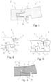
- the inclined assembly opposing edges (2) consist of an edge comprising male coupling means (4) provided from a side wall of the panel (1), and an opposing edge comprising complementary female coupling means (5) provided from a side wall of the panel (1).
- the vertically assembled opposite edges (3) consist of an edge comprising male coupling means (6) provided from a lower face of the panel (1), and an opposite edge comprising complementary female coupling means (7) provided from an upper face of the panel (1).
- the upper and facing edges of two panels (1) are preferably in contact for optimal aesthetics.
- the male coupling means (4) of the inclined assembly edges (2) comprise a tab (8) projecting from the side wall of the panel (1) and over the entire length of the edge.
- the female coupling means (5) of the inclined assembly edges (2) comprise a complementary groove (9) provided in the side wall of the panel (1) and over the entire length of the edge.
- the tongue (8) comprises a lug (8a) projecting vertically
- the complementary groove (9) comprises a complementary notch (9a) forming, after assembly of two adjacent panels (1), stops against horizontal movement between two adjacent assembled panels (1).
- the tongue (8) may comprise a notch and the groove (9) may comprise a lug, without departing from the scope of the invention.
- the engagement of the tongue (8) in the groove (9) is carried out according to an inclined kinematics, then by pivoting the panel (1), the tongue (8) is moved horizontally towards the bottom of the groove.
- the groove (9) complementary to the female coupling means (5) defines a lower female tab (9b) flexible and intended to move away during the inclined engagement of the tab (8) of the male coupling means (4), then to resume its position after engagement to increase the resistance to vertical and horizontal disassembly of two adjacent assembled panels (1).
- the male coupling means (6) of the vertically assembled edges (3) comprise a male groove (6a) extending along the edge and opening onto the lower face of the panel (1), so as to define a male tenon (6b).
- the female coupling means (7) of the vertically assembled edges (3) comprise a female groove (7a) extending along the edge and opening onto the upper face of the panel (1), so as to define a female tenon (7b).
- the male and female tenons (6b, 7b) comprise substantially rectangular cross-sections, and are flexible and elastically deformable to allow their engagement in the corresponding female and male grooves (6a, 7a).
- the male tenon (6b) has an external wall (6c) inclined relative to a vertical plane and towards the outside of the panel (1), at an angle of between 1 and 45°, and preferably between 5 and 15°.
- An inclination of the external wall (6c) of between 5 and 15° makes it possible to obtain a good compromise between the ease of assembly of the panels and the resistance to horizontal disassembly of the coupling means.
- the installer sees the female groove (7a) and can therefore easily position the external wall (6c) of the male tenon (6b) at the level of the female groove (7a) to begin assembly.
- the two panels (1) move closer to each other. This further facilitates the installation operation, and the machining constraints for having perfect surface contact of the panels (1) are also easier to respect.
- the male tenon (6b) has an internal wall inclined relative to a vertical plane and towards the outside or the inside of the panel (1).
- the male tenon (6b) has an internal wall inclined towards the outside of the panel (1), at an angle of between 1 and 45°, and preferably between 5 and 15°.
- An inclination of the internal wall of the male tenon (6b) of between 5 and 15° also makes it possible to obtain a good compromise between the ease of assembly of the panels and the resistance to horizontal disassembly of the coupling means.
- the male tenon (6b) has an internal wall inclined at the same angle as the external wall (6c). This characteristic also makes it possible to facilitate the manufacture, and in particular the machining of the complementary male (6) and female (7) coupling means.
- the male coupling means (6) of the vertically assembled edges (3) comprise a lug (10) or a notch (11), and the female coupling means (7) of the vertically assembled edges (3) comprise a complementary notch (11) or lug (10) forming, after assembly of two adjacent panels (1), stops against vertical movement between two adjacent assembled panels (1).
- the lug (10) or notch (11) is provided on the external wall of the male tenon (6b) and, in a complementary manner, the notch (11) or lug (10) is provided on an internal wall of the female groove (7a).
- the lug (10) or notch (11) is provided on the external wall of the female tenon (7b) and, in a complementary manner, the notch (11) or lug (10) is provided on an internal wall of the male groove (6a).
- these two embodiments are combined so that the male coupling means (6) of the vertically assembled edges (3) comprise two lugs (10) or notches (11), and the female coupling means (7) of the vertically assembled edges (3) comprise two complementary notches (11) or lugs (10).
- the male (6a) and female (7a) grooves each have an external wall, i.e. positioned, not on the side of the body of the panel (1), but on the side of the outside of the panel (1), intended to be in contact, after assembly of the two panels (1).
- the grooves (6a, 7a) and tenons (6b, 7b) have appropriate widths and/or inclinations.
- the tenons (6b, 7b) and grooves (6a, 7a) have widths of the order of 2 mm, and are inclined by 10° relative to the vertical and towards the outside of the panel (1).
- the external wall of the male groove (6a) is in contact with the external wall of the female groove (7a).
- these walls in contact are parallel to each other.
- the male tenon (6b) is in contact with the bottom of the female groove (7a) in order to have a vertical support.
- the female tenon (7b) comprises a chamfered portion (12) at the lower face of the panel (1) and forming an angle of between 2° and 20° relative to the lower face of the panel (1).
- the chamfered portion (12) allows the lowering of the female tenon (7b) to come, by deformation, into contact with the ground, and thus provide a reduction in the assembly effort.
- the chamfered portion (12) of the female tenon (7b) extends to the right of the internal upper edge of the female tenon (7b).
- the upper face of the panel (1) may also have chamfers (13) at the male tenon (6b) and the female groove (7a) in order to contribute to the general aesthetics of the panels (1), after assembly.
- Each chamfer (13) forms an angle of between 2° and 20° relative to the upper face of the panel (1).
- the interface between the two assembled panels (1) thus forms a V-shaped groove, see figure 5 .
- the invention provides a panel (1) for producing a loose-lay floor covering, the assembly of which is facilitated, while having optimum resistance to horizontal and vertical disassembly, as well as satisfactory aesthetics.
Landscapes
- Engineering & Computer Science (AREA)
- Architecture (AREA)
- Civil Engineering (AREA)
- Structural Engineering (AREA)
- Floor Finish (AREA)
- Finishing Walls (AREA)
Applications Claiming Priority (3)
| Application Number | Priority Date | Filing Date | Title |
|---|---|---|---|
| FR1873754A FR3090711B1 (fr) | 2018-12-21 | 2018-12-21 | Panneau pour la realisation d’un revêtement de sol en pose libre |
| EP19845821.8A EP3899164B1 (de) | 2018-12-21 | 2019-12-17 | Paneel zur herstellung eines lose verlegten bodenbelags |
| PCT/FR2019/053128 WO2020128309A1 (fr) | 2018-12-21 | 2019-12-17 | Panneau pour la realisation d'un revêtement de sol en pose libre |
Related Parent Applications (2)
| Application Number | Title | Priority Date | Filing Date |
|---|---|---|---|
| EP19845821.8A Division-Into EP3899164B1 (de) | 2018-12-21 | 2019-12-17 | Paneel zur herstellung eines lose verlegten bodenbelags |
| EP19845821.8A Division EP3899164B1 (de) | 2018-12-21 | 2019-12-17 | Paneel zur herstellung eines lose verlegten bodenbelags |
Publications (2)
| Publication Number | Publication Date |
|---|---|
| EP4464857A2 true EP4464857A2 (de) | 2024-11-20 |
| EP4464857A3 EP4464857A3 (de) | 2024-11-27 |
Family
ID=67441189
Family Applications (2)
| Application Number | Title | Priority Date | Filing Date |
|---|---|---|---|
| EP24205296.7A Pending EP4464857A3 (de) | 2018-12-21 | 2019-12-17 | Paneel zur herstellung eines lose verlegten bodenbelags |
| EP19845821.8A Active EP3899164B1 (de) | 2018-12-21 | 2019-12-17 | Paneel zur herstellung eines lose verlegten bodenbelags |
Family Applications After (1)
| Application Number | Title | Priority Date | Filing Date |
|---|---|---|---|
| EP19845821.8A Active EP3899164B1 (de) | 2018-12-21 | 2019-12-17 | Paneel zur herstellung eines lose verlegten bodenbelags |
Country Status (6)
| Country | Link |
|---|---|
| US (2) | US11891816B2 (de) |
| EP (2) | EP4464857A3 (de) |
| CN (1) | CN113383137A (de) |
| FR (1) | FR3090711B1 (de) |
| PL (1) | PL3899164T3 (de) |
| WO (1) | WO2020128309A1 (de) |
Families Citing this family (8)
| Publication number | Priority date | Publication date | Assignee | Title |
|---|---|---|---|---|
| US20190143836A1 (en) * | 2017-11-13 | 2019-05-16 | Ford Global Technologies, Llc | Thermal exchange plate of a vehicle battery pack and thermal exchange plate assembly method |
| FR3090711B1 (fr) * | 2018-12-21 | 2022-02-04 | Gerflor | Panneau pour la realisation d’un revêtement de sol en pose libre |
| US11952784B2 (en) * | 2019-01-30 | 2024-04-09 | I4F Licensing Nv | Panel and covering comprising the same |
| FR3105280B1 (fr) * | 2019-12-23 | 2021-11-26 | Gerflor | Panneau pour la réalisation d’un revêtement de sol en pose libre |
| BE1028427B1 (nl) * | 2020-06-24 | 2022-02-01 | Flooring Ind Ltd Sarl | Vloerpanelen en werkwijze voor het vervaardigen van vloerpanelen en snijgereedschappen hierbij aangewend |
| RU205565U1 (ru) * | 2021-05-10 | 2021-07-21 | Ксения Валерьевна Мезенцева | Полимерная плитка |
| CN120476238A (zh) * | 2023-01-10 | 2025-08-12 | 瓦林格创新股份有限公司 | 包括锁定装置的一组建筑镶板 |
| FR3150825B1 (fr) | 2023-07-04 | 2025-09-26 | Gerflor | Revêtement de sol sportif en dalle ou lame |
Citations (2)
| Publication number | Priority date | Publication date | Assignee | Title |
|---|---|---|---|---|
| US20130309441A1 (en) | 2011-01-28 | 2013-11-21 | Akzenta Paneele + Profile Gmbh | Panel |
| EP3105392A1 (de) | 2014-02-26 | 2016-12-21 | Innovations 4 Flooring Holding N.V. | Paneel, das mit ähnlichen paneelen verbindbar ist, zur formung einer abdeckung |
Family Cites Families (22)
| Publication number | Priority date | Publication date | Assignee | Title |
|---|---|---|---|---|
| BE1010487A6 (nl) * | 1996-06-11 | 1998-10-06 | Unilin Beheer Bv | Vloerbekleding bestaande uit harde vloerpanelen en werkwijze voor het vervaardigen van dergelijke vloerpanelen. |
| SE515789C2 (sv) * | 1999-02-10 | 2001-10-08 | Perstorp Flooring Ab | Golvbeläggningsmaterial innefattande golvelement vilka är avsedda att sammanfogas vertikalt |
| GB0004199D0 (en) * | 2000-02-22 | 2000-04-12 | Winsbury Barry | System |
| SE522860C2 (sv) * | 2000-03-10 | 2004-03-09 | Pergo Europ Ab | Vertikalt förenade golvelement innefattande en kombination av olika golvelement |
| WO2007067789A2 (en) * | 2005-12-08 | 2007-06-14 | Armstrong World Industries, Inc. | Wide width lock and fold laminate |
| DE102007042840B4 (de) * | 2007-09-10 | 2010-04-22 | Flooring Technologies Ltd. | Paneel, insbesondere Bodenpaneel |
| DE202008010555U1 (de) * | 2008-08-08 | 2009-12-17 | Akzenta Paneele + Profile Gmbh | Kunststoffpaneel mit Hakenprofil |
| DE202008011589U1 (de) * | 2008-09-01 | 2008-11-27 | Akzenta Paneele + Profile Gmbh | Fußbodenpaneel aus Kunststoff mit mechanischen Verriegelungskanten |
| PL2208835T3 (pl) * | 2009-01-16 | 2012-10-31 | Vaelinge Innovation Ab | Panel, zwłaszcza panel podłogowy |
| US8763340B2 (en) * | 2011-08-15 | 2014-07-01 | Valinge Flooring Technology Ab | Mechanical locking system for floor panels |
| CN109025154B (zh) * | 2012-06-19 | 2021-04-02 | 瓦林格创新股份有限公司 | 将板块分为第一和第二镶板的方法、形成机械锁定系统的方法以及建筑镶板 |
| WO2015070890A1 (en) * | 2013-11-12 | 2015-05-21 | Grigorij Wagner | Flooring component |
| FR3024990B1 (fr) * | 2014-08-25 | 2018-11-16 | Gerflor | Panneau de sol pour la realisation d'un revetement. |
| US10309113B2 (en) * | 2015-01-16 | 2019-06-04 | Flooring Industries Limited, Sarl | Floor panel for forming a floor covering |
| WO2018063047A1 (en) * | 2016-09-30 | 2018-04-05 | Välinge Innovation AB | Set of panels assembled by vertical displacement and locked together in the vertical and horizontal direction |
| EP4234837B1 (de) * | 2018-01-09 | 2026-02-04 | Välinge Innovation AB | Paneelsatz |
| SE542114C2 (en) * | 2018-01-27 | 2020-02-25 | Ipendor Ab | Joining system for floor panels |
| BE1026806B1 (nl) * | 2018-11-27 | 2020-06-30 | Flooring Ind Ltd Sarl | Paneel en werkwijze voor het vervaardigen van dergelijk paneel |
| WO2020117117A1 (en) * | 2018-12-05 | 2020-06-11 | Välinge Innovation AB | Subfloor joint |
| FR3090711B1 (fr) | 2018-12-21 | 2022-02-04 | Gerflor | Panneau pour la realisation d’un revêtement de sol en pose libre |
| HUE054623T2 (hu) * | 2019-03-12 | 2021-09-28 | Flooring Technologies Ltd | Kemény padlópanel úsztatott fektetésre padlópanel együttes kialakításához |
| BE1027299B1 (nl) * | 2019-05-22 | 2020-12-22 | Flooring Ind Ltd Sarl | Vloerpaneel voor het vormen van een vloerbekleding |
-
2018
- 2018-12-21 FR FR1873754A patent/FR3090711B1/fr active Active
-
2019
- 2019-12-17 WO PCT/FR2019/053128 patent/WO2020128309A1/fr not_active Ceased
- 2019-12-17 EP EP24205296.7A patent/EP4464857A3/de active Pending
- 2019-12-17 CN CN201980090939.2A patent/CN113383137A/zh active Pending
- 2019-12-17 PL PL19845821.8T patent/PL3899164T3/pl unknown
- 2019-12-17 EP EP19845821.8A patent/EP3899164B1/de active Active
- 2019-12-17 US US17/415,745 patent/US11891816B2/en active Active
-
2023
- 2023-12-20 US US18/389,873 patent/US12435524B2/en active Active
Patent Citations (2)
| Publication number | Priority date | Publication date | Assignee | Title |
|---|---|---|---|---|
| US20130309441A1 (en) | 2011-01-28 | 2013-11-21 | Akzenta Paneele + Profile Gmbh | Panel |
| EP3105392A1 (de) | 2014-02-26 | 2016-12-21 | Innovations 4 Flooring Holding N.V. | Paneel, das mit ähnlichen paneelen verbindbar ist, zur formung einer abdeckung |
Also Published As
| Publication number | Publication date |
|---|---|
| US20240117641A1 (en) | 2024-04-11 |
| WO2020128309A1 (fr) | 2020-06-25 |
| EP3899164A1 (de) | 2021-10-27 |
| EP3899164B1 (de) | 2024-11-27 |
| EP4464857A3 (de) | 2024-11-27 |
| FR3090711B1 (fr) | 2022-02-04 |
| US12435524B2 (en) | 2025-10-07 |
| US11891816B2 (en) | 2024-02-06 |
| CN113383137A (zh) | 2021-09-10 |
| US20210381256A1 (en) | 2021-12-09 |
| FR3090711A1 (fr) | 2020-06-26 |
| PL3899164T3 (pl) | 2025-02-17 |
| EP3899164C0 (de) | 2024-11-27 |
Similar Documents
| Publication | Publication Date | Title |
|---|---|---|
| EP3899164B1 (de) | Paneel zur herstellung eines lose verlegten bodenbelags | |
| EP3891349B1 (de) | Vertikal montierte platte zur herstellung eines belags | |
| EP2852502B1 (de) | Windschutzfenster mit einer scheibe, die mit einer integrierten einlage ausgerüstet ist, die eine zu einem träger des fahrzeugrahmens passende form aufweist | |
| FR2831908A1 (fr) | Dispositif d'assemblage des bords de panneaux, lattes ou lambris | |
| WO2001088307A1 (fr) | Dispositif d'assemblage des bords longitudinaux de panneaux, lattes ou lambris, a repartition de forces | |
| BE1019657A3 (fr) | Ensemble de finition pour surfaces disjointes, comportant un profil de jonction separable en deux modules aptes a former des profils d'arret. | |
| FR2826391A1 (fr) | Dispositif d'assemblage des bords de panneaux, lattes ou lambris | |
| EP4045732A1 (de) | Paneel zum herstellen eines selbstsperrenden bodenbelages | |
| EP2360381B1 (de) | Anschlusselement für Schwellenleiste | |
| FR3131593A1 (fr) | Panneau de revêtement de sol ou mur à résistance accrue au désassemblage | |
| BE1020136A3 (fr) | Ensemble de finition multifonction pour revetement de sol, comportant un profil modulaire forme d'au moins deux pieces et un film applique sur les deux pieces. | |
| FR3000512A1 (fr) | Accessoire de finition deformable adapte pour former un raccord entre deux surfaces | |
| EP3036384B1 (de) | Besatzstreifen zum zusammenfügen durch selbstverriegelnde kopplung und installationszubehör zur befestigung davon an einer wand und verfahren zum verlegen | |
| FR2808824A1 (fr) | Dispositif d'assemblage des bords longitudinaux de panneaux, lattes ou lambris, a repartition de forces | |
| FR2968740A1 (fr) | Piece d'etancheite bi-matiere et toiture de panneaux photovoltaiques comprenant une telle piece | |
| FR2889219A1 (fr) | Panneaux a assembler par rotation et profils correspondants | |
| WO2002101175A1 (fr) | Dispositif d'assemblage de panneaux, lattes ou lambris, a repartition de forces | |
| EP4446516A1 (de) | Verbesserte vorrichtung zum verbinden von aneinanderliegenden und in der kante angeordneten platten oder platten an einer boden- oder wandabdeckung | |
| FR2807694A1 (fr) | Dispositif d'assemblage des bords longitudinaux de panneaux, lattes ou lambris | |
| FR2808825A1 (fr) | Dispositif d'assemblage des bords longitudinaux de panneaux, lattes ou lambris, a repartition de forces | |
| FR2910034A1 (fr) | Procede de realisation d'un parquet a lames adjacentes, et parquet ainsi constitue | |
| FR2880047A1 (fr) | Panneau de plancher demontable | |
| EP1985791A2 (de) | Lamelle aus Metall für Rolläden oder Sektionaltore | |
| FR2808823A1 (fr) | Dispositif d'assemblage des bords longitudinaux de panneaux, lattes ou lambris, a repartition de forces |
Legal Events
| Date | Code | Title | Description |
|---|---|---|---|
| PUAI | Public reference made under article 153(3) epc to a published international application that has entered the european phase |
Free format text: ORIGINAL CODE: 0009012 |
|
| STAA | Information on the status of an ep patent application or granted ep patent |
Free format text: STATUS: THE APPLICATION HAS BEEN PUBLISHED |
|
| PUAL | Search report despatched |
Free format text: ORIGINAL CODE: 0009013 |
|
| AC | Divisional application: reference to earlier application |
Ref document number: 3899164 Country of ref document: EP Kind code of ref document: P |
|
| AK | Designated contracting states |
Kind code of ref document: A2 Designated state(s): AL AT BE BG CH CY CZ DE DK EE ES FI FR GB GR HR HU IE IS IT LI LT LU LV MC MK MT NL NO PL PT RO RS SE SI SK SM TR |
|
| AK | Designated contracting states |
Kind code of ref document: A3 Designated state(s): AL AT BE BG CH CY CZ DE DK EE ES FI FR GB GR HR HU IE IS IT LI LT LU LV MC MK MT NL NO PL PT RO RS SE SI SK SM TR |
|
| RIC1 | Information provided on ipc code assigned before grant |
Ipc: E04F 15/02 20060101AFI20241021BHEP |
|
| STAA | Information on the status of an ep patent application or granted ep patent |
Free format text: STATUS: REQUEST FOR EXAMINATION WAS MADE |
|
| 17P | Request for examination filed |
Effective date: 20250522 |