EP4464852A1 - Timber building structure - Google Patents
Timber building structure Download PDFInfo
- Publication number
- EP4464852A1 EP4464852A1 EP23173611.7A EP23173611A EP4464852A1 EP 4464852 A1 EP4464852 A1 EP 4464852A1 EP 23173611 A EP23173611 A EP 23173611A EP 4464852 A1 EP4464852 A1 EP 4464852A1
- Authority
- EP
- European Patent Office
- Prior art keywords
- clamping element
- clamping
- column
- timber
- building structure
- Prior art date
- Legal status (The legal status is an assumption and is not a legal conclusion. Google has not performed a legal analysis and makes no representation as to the accuracy of the status listed.)
- Withdrawn
Links
Images




Classifications
-
- E—FIXED CONSTRUCTIONS
- E04—BUILDING
- E04B—GENERAL BUILDING CONSTRUCTIONS; WALLS, e.g. PARTITIONS; ROOFS; FLOORS; CEILINGS; INSULATION OR OTHER PROTECTION OF BUILDINGS
- E04B1/00—Constructions in general; Structures which are not restricted either to walls, e.g. partitions, or floors or ceilings or roofs
- E04B1/18—Structures comprising elongated load-supporting parts, e.g. columns, girders, skeletons
- E04B1/26—Structures comprising elongated load-supporting parts, e.g. columns, girders, skeletons the supporting parts consisting of wood
- E04B1/2604—Connections specially adapted therefor
-
- E—FIXED CONSTRUCTIONS
- E04—BUILDING
- E04B—GENERAL BUILDING CONSTRUCTIONS; WALLS, e.g. PARTITIONS; ROOFS; FLOORS; CEILINGS; INSULATION OR OTHER PROTECTION OF BUILDINGS
- E04B5/00—Floors; Floor construction with regard to insulation; Connections specially adapted therefor
- E04B5/02—Load-carrying floor structures formed substantially of prefabricated units
- E04B5/12—Load-carrying floor structures formed substantially of prefabricated units with wooden beams
-
- E—FIXED CONSTRUCTIONS
- E04—BUILDING
- E04B—GENERAL BUILDING CONSTRUCTIONS; WALLS, e.g. PARTITIONS; ROOFS; FLOORS; CEILINGS; INSULATION OR OTHER PROTECTION OF BUILDINGS
- E04B1/00—Constructions in general; Structures which are not restricted either to walls, e.g. partitions, or floors or ceilings or roofs
- E04B1/18—Structures comprising elongated load-supporting parts, e.g. columns, girders, skeletons
- E04B1/26—Structures comprising elongated load-supporting parts, e.g. columns, girders, skeletons the supporting parts consisting of wood
- E04B1/2604—Connections specially adapted therefor
- E04B2001/2644—Brackets, gussets or joining plates
-
- E—FIXED CONSTRUCTIONS
- E04—BUILDING
- E04B—GENERAL BUILDING CONSTRUCTIONS; WALLS, e.g. PARTITIONS; ROOFS; FLOORS; CEILINGS; INSULATION OR OTHER PROTECTION OF BUILDINGS
- E04B1/00—Constructions in general; Structures which are not restricted either to walls, e.g. partitions, or floors or ceilings or roofs
- E04B1/18—Structures comprising elongated load-supporting parts, e.g. columns, girders, skeletons
- E04B1/26—Structures comprising elongated load-supporting parts, e.g. columns, girders, skeletons the supporting parts consisting of wood
- E04B1/2604—Connections specially adapted therefor
- E04B2001/2676—Connector nodes
-
- E—FIXED CONSTRUCTIONS
- E04—BUILDING
- E04B—GENERAL BUILDING CONSTRUCTIONS; WALLS, e.g. PARTITIONS; ROOFS; FLOORS; CEILINGS; INSULATION OR OTHER PROTECTION OF BUILDINGS
- E04B1/00—Constructions in general; Structures which are not restricted either to walls, e.g. partitions, or floors or ceilings or roofs
- E04B1/18—Structures comprising elongated load-supporting parts, e.g. columns, girders, skeletons
- E04B1/26—Structures comprising elongated load-supporting parts, e.g. columns, girders, skeletons the supporting parts consisting of wood
- E04B1/2604—Connections specially adapted therefor
- E04B2001/2692—End to end connections of elongated members along their common longitudinal axis
-
- E—FIXED CONSTRUCTIONS
- E04—BUILDING
- E04B—GENERAL BUILDING CONSTRUCTIONS; WALLS, e.g. PARTITIONS; ROOFS; FLOORS; CEILINGS; INSULATION OR OTHER PROTECTION OF BUILDINGS
- E04B1/00—Constructions in general; Structures which are not restricted either to walls, e.g. partitions, or floors or ceilings or roofs
- E04B1/38—Connections for building structures in general
- E04B1/61—Connections for building structures in general of slab-shaped building elements with each other
- E04B1/6108—Connections for building structures in general of slab-shaped building elements with each other the frontal surfaces of the slabs connected together
- E04B2001/6191—Connections for building structures in general of slab-shaped building elements with each other the frontal surfaces of the slabs connected together by means on the corners of the slabs
-
- E—FIXED CONSTRUCTIONS
- E04—BUILDING
- E04C—STRUCTURAL ELEMENTS; BUILDING MATERIALS
- E04C3/00—Structural elongated elements designed for load-supporting
- E04C3/30—Columns; Pillars; Struts
- E04C3/36—Columns; Pillars; Struts of materials not covered by groups E04C3/32 or E04C3/34; of a combination of two or more materials
Definitions
- the invention relates to a building structure according to the preamble of claim 1.
- the invention lies in the field of connectors for structural mass timber, in particular for mid- to high-rise buildings.
- Mass timber construction for mid- to high-rise buildings is a relatively new and growing field.
- the standard structural concept for buildings is the so-called "post-and-beam" structure.
- the vertical loads i.e. mainly gravitational loads from dead weight, snow, usage and others
- the vertical loads are supported by floors, which floors rest on horizontal beams, which horizontal beams are supported by vertical posts.
- a relatively new structural concept is the so-called "post-and-plate” or "point-supported” timber system.
- the vertical loads are supported by floor slabs, which rest directly on posts.
- This second concept offers advantages over post-and-beam systems, because the floor height or storey height, respectively, is smaller, due to the fact that there are no beams.
- the total mass of timber needed for the building can be reduced.
- WO23277706 A1 discloses a coupler for timber columns that includes a ratchet mechanism including pawl wedges sliding on a tapered conical surface, wherein the ratchet mechanism allows insertion of a connector rod whilst preventing withdrawal of the connector rod in the opposite direction.
- the invention provides a building structure comprising
- the upper column rests (directly or indirectly) on the floor slabs, namely on the metal clamping elements thereof, which floor slabs, namely at their respective metal clamping elements, rest (directly or indirectly) on the lower column.
- the lower column bears the floor slabs, namely at their respective metal clamping elements, whereas the floor slabs, namely at their respective metal clamping elements, bear the upper column.
- Clamping of the first clamping element, the second clamping element and, if available, additional clamping elements can be direct or indirect, i.e. via another member.
- the another member might also include hardended mortar.
- mortar might be placed and hardened at the clamping sites in order to compensate tolerances.
- the panels of the respective floor slabs are timber slabs, i.e. they consist of timber. It is particularly preferred that they consist of engineered timber (i.e. of a material consisting of timber lamellas glued together). In particular, the panels can consist of cross laminated timber.
- the (upper and lower) columns are timber columns, i.e. they consist of timber. It is particularly preferred that they consist of engineered timber (i.e. of a material consisting of timber lamellas glued together). In particular, the timber columns can consist of glulam.
- the lower column and the upper column extend generally in the vertical direction when the building structure is installed as intended.
- the upper column is arranged above the lower column, i.e. the upper column is in a in a higher position than the lower column, in particular with respect to the local field of gravity.
- the upper column is aligned with the lower column. Accordingly, they at least partly overlap in a vertically directed parallel projection.
- the vertically and horizontal directions should, in particular, refer to the local field of gravity.
- the lower column is in particular arranged below the higher column, i.e. the lower column is arranged closer to the local point of gravity than is the higher column.
- the timber panels are plates. Accordingly, the first timber panel has two flat main surfaces, which are generally parallel to one another, and a lateral surface that extends between the two main surfaces, and the second timber panel has two flat main surfaces, which are generally parallel to one another, and a lateral surface that extends between the two main surfaces.
- the first clamping element is arranged in front of the lateral surface of the first timber panel, and/or the second clamping element is arranged in front of the lateral surface of the second timber panel.
- This can provide particularly effective force transfer, in particular by avoiding undesired lever arms.
- first clamping element contacts the lateral surface of the first timber panel
- second clamping element contacts the lateral surface of the second timber panel. This can also be advantageous in view of effective force transfer, in particular by avoiding undesired lever arms.
- the first clamping element has a first structured panel contact surface that contacts the lateral surface of the first timber panel and/or the second clamping element has a second structured panel contact surface that contacts the lateral surface of the second timber panel.
- Providing structured contact surfaces can be advantageous in view of force transfer and can in particular provide particularly good shear transfer.
- a structured surface may not be flat, but provided with, preferably deterministic, patterns of generally high aspect ratio geometric features.
- the respective panel contact surfaces can e.g. include a plurality of protruding spikes.
- the first clamping element is attached to the first timber panel at the lateral surface of the first timber panel, preferably by at least one screw extending through the first clamping element into the first timber panel
- the second clamping element is attached to the second timber panel at the lateral surface of the second timber panel, preferably by at least one screw extending through the second clamping element into the second timber panel.
- Clamping element attachment at the respective lateral sides can further improve force transfer.
- using at least one screw for this purpose can provide particularly easy and efficient fastening.
- it can provide pressure of the clamping elements against the respective timber panel in particular easy manner, which can be advantageous in view of shear force transfer (in particular in connection with a structured panel contact surface).
- the first clamping element is arranged in front of an edge region of the lateral surface of the first timber panel, and/or the second clamping element is arranged in front of an edge region of the lateral surface of the second timber panel.
- the lateral surface of the respective timber panel comprises (at least) two flat faces, between which the respective edge region is located.
- the first clamping element is wedge shaped so as to form an edge
- the second clamping element is wedge shaped so as to form an edge.
- the respective clamping elements taper with increasing distance from the respective timber panel. This allows for particularly compact arrangement of the floor slabs, in particular when more than two floor slabs are connected at a single connection point.
- the clamping elements are metal elements, i.e. they consist of metal.
- the first clamping element is a steel element and/or the second clamping element is a steel element. Using steel can be particularly advantageous in view of availability and performance.
- the first clamping element is an aluminium element and/or the second clamping element is an aluminium element.
- first clamping element is a solid element, more preferably a solid steel element and/or that the second clamping element is a solid element, more preferably a solid steel element.
- solid elements i.e. non-hollow elements
- the clamping elements can be monolithic.
- at least one of the first clamping element or the second clamping element could be a non-monolithic element, which could e.g. consist of sub-elements, such as plates, which are welded together.
- the first clamping element comprises a upper clamping surface facing the upper column and a lower clamping surface facing the lower column, wherein, preferably, at least one of the upper clamping surface and the lower clamping surface of the first clamping element is structured, and/or that the second clamping element comprises an upper clamping surface facing the upper column and a lower clamping surface facing the lower column, wherein, preferably, at least one of the upper clamping surface and the lower clamping surface of the second clamping element is structured.
- each clamping element has two opposite clamping surfaces for direct or indirect column contact.
- at least one, preferably both, of these clamping surfaces is structured. This can provide particularly good shear transfer and provide a particularly stiff node, which can be advantageous in view of slab to slab load transfer.
- a structured clamping surface might include a one-dimensionally undulated contact surface or a two-dimensionally undulated contact surface.
- the first clamping element projects between the upper column and the lower column. Accordingly, there is at least one vertical straight line that includes both the upper column, the lower column and the first clamping element. Accordingly, at least parts of the first clamping element, the upper column and the lower column overlap in a vertically directed parallel projection. In other words, at least parts of the first clamping element is horizontally aligned and non-offset with both the upper column and the lower column. This can be advantageous in view of force transfer and can provide a particularly compact design. Analogously, it is preferred that the second clamping element, at least partly, projects between the upper column and the lower column.
- the building structure further comprises a metal upper clamping plate, which contacts the upper column at an upper contact surface of the upper clamping plate, and which contacts the first and second clamping elements on a lower contact surface of the upper clamping plate.
- a metal upper clamping plate which contacts the upper column at an upper contact surface of the upper clamping plate, and which contacts the first and second clamping elements on a lower contact surface of the upper clamping plate.
- Contact between the first and second clamping elements and the lower contact surface of the upper clamping plate can be direct contact, but also indirect contact, e.g. via a lateral-force transmittal plate, like the one described further below.
- the building structure may further comprise a metal lower clamping plate, which contacts the lower column at a lower contact surface of the lower clamping plate, and which contacts the first and second clamping elements on an upper contact surface of the lower clamping plate.
- At least one of the contact surfaces is preferably structured, wherein structure can for example include one-dimensional undulations, two-dimensional undulations or spikes.
- the building structure further comprises a tension rod, preferably a metal tension rod, more preferably a steel tension rod, which is anchored both in the upper column and in the lower column. This allows to transmit tension between the columns, which can further improve performance and robustness.
- a tension rod preferably a metal tension rod, more preferably a steel tension rod, which is anchored both in the upper column and in the lower column. This allows to transmit tension between the columns, which can further improve performance and robustness.
- the tension rod is anchored in the lower column by means of a glued connection.
- This can provide a particular easy-to manufacture prefabricated connection.
- the tension rod is anchored in the upper column by means of a ratchet mechanism.
- a ratchet mechanism allows insertion of a rod whilst preventing withdrawal of rod in the opposite direction.
- the ratchet mechanism might include several types of pawls, such as rotating pawls or pawl wedges sliding on a tapered surface.
- the ratchet mechanism can be provided on the upper column and can be intended to engage the tension rod. Alternatively, in can be provided on the tension rod and be intended to engage an auxiliary rod that is anchored within the upper column.
- the first clamping element and the second clamping element surround the tension rod, which allows for a particular compact design.
- the tension rod is preferentially at least partly threaded, which can facilitate engagement.
- the building structure further comprises a hold-down nut, which is screwed onto the metal tension rod so as to tension the first and second clamping elements against the lower column.
- the hold-down nut can act directly against the clamping elements so as to tension them against the lower column.
- the hold-down acts indirectly, in particular via the upper clamping plate, against the clamping elements so as to tension them against the lower column.
- Providing a hold-down nut can provide a pre-installation configuration, in which the floor slabs are secured before the upper column is installed, in a particular easy manner. Additionally or alternatively, it can ensure that clamping is upheld even when rotational movement occurs, thereby ensuring particular satisfactory performance in various load situations.
- the hold-down nut and the ratchet mechanism can be integrated into a single component.
- the building structure comprises at least a first a first floor slab and a second floor slab.
- the building structure might also comprise a third floor slab and/or a fourth floor slab.
- the building structure comprises:
- a second floor slab, a third floor slab and/or a fourth floor slab are preferably deigned in analogy to the first floor slab.
- first floor slab and/or the second floor slab
- the remaining floor slabs can preferably be provided in analogy to the first floor slab, but also differently.
- Figures 1 to 5 show successive steps during the installation of a building structure.
- a timber column which intended to be the lower column 10 of the structure, is supplied.
- a metal lower clamping plate 15 is attached to a face of the lower column 10, which face is intended to be an upper face of the lower column 10.
- a tension rod 50 is anchored within the lower column 10, so that the tension rod 50 protrudes from the lower column 10 through the lower clamping plate 15. Attaching the clamping plate 15 and/or the tension rod is 50 preferably done off-site, before shipment of the lower clamping plate 15 to the construction site.
- the lower column 10 is brought into a vertical position, with the clamping plate 15 and the tension rod 50 located on top of the lower column. The resulting configuration is shown in figure 1 .
- a first floor slab 30', a second floor slab 30", a third floor slab 30'", and a fourth floor slab 30 ⁇ are then provided.
- the first floor slab 30' includes a first timber panel 31'.
- the first floor slab 30' further includes a first clamping element 40', consisting of steel, which is attached to the first timber panel 31'.
- the second floor slab 30" comprises a second timber panel 31" and a second clamping element 40", consisting of steel, which is attached to the second timber panel 31
- the third floor slab 30′′′ comprises a third timber panel 31′′′ and a third clamping element 40'", consisting of steel, which is attached to the third timber panel 31′′′
- the fourth floor slab 30 ⁇ comprises a fourth timber panel 31"” and a fourth clamping element 40 ⁇ , consisting of steel, which is attached to the fourth timber panel 31 ⁇ .
- the floor slabs 30', 30", 30'", 30”” are positioned so that the respective clamping elements 40', 40", 40′′′, 40 ⁇ rest on the lower clamping plate 15 and therefore, indirectly, on the lower column 10.
- the resulting configuration is shown in figure 3 .
- protruding centring pins 99 can be provided on the lower clamping plate 15, which can secure the floor slabs 30', 30", 30'", 30"” in this phase by engaging the respective clamping elements 40', 40", 40′′′, 40 ⁇ .
- An upper clamping plate 25 is then placed on the respective clamping elements 40', 40", 40'", 40”".
- the upper clamping plate 25 is provided with a hole that receives the tension rod 50 as the upper clamping plate 25 is placed on the respective clamping elements 40', 40", 40'", 40”", so that the tension rod 50 passes through the upper clamping plate 25 and projects therefrom.
- a hold-down nut 59 is then screwingly placed on the tension rod 50 and tightened thereon, whilst acting against the upper clamping plate 25, thereby clamping the clamping elements 40', 40", 40'", 40”” between the upper clamping plate 25 on one side and the lower clamping plate 15 and the lower column 10 on the other side.
- the resulting configuration is shown in figure 4 .
- An upper column 20 is then provided and placed (in aligned relationship with the lower column 10) on the upper clamping plate 25.
- the upper column 20 then rests, via the upper clamping plate 25, on the clamping elements 40', 40", 40'", 40"". Accordingly, the clamping elements 40', 40", 40'", 40”" are thus clamped between the lower column 10 and the upper column 20.
- hardened mortar might be provided adjacent to at least one of the clamping elements 40', 40", 40'", 40"".
- the upper column 20 has an opening that receives the tension rod 50 as the upper column 20 is positioned on the upper clamping plate 25.
- a ratchet mechanism 90 (shown schematically in figure 5 only), might be provided on the tension rod 50 or/and in the upper column 20 to anchor the tension rod 50 within the upper column 20 for transferring tensile loads between the tension rod 50 and the upper column 20.
- the floor slabs 30', 30", 30'", 30 ⁇ are described in greater detail.
- the second floor slab 30", the third floor slab 30'", and the fourth floor slab 30 ⁇ are realized in analogy to the first floor slab 30', i.e. the design and the materials are analogous. Therefore, and for the sake of brevity, the following explanations refer to the first floor slab 30' only. However, unless indicated otherwise, features mentioned in connection with the first floor slab 30' can apply to the remaining flow slabs 30", 30'", 30 ⁇ in analogous manner.
- the first timber panel 31' of the first floor slab 30' is generally plate-shaped and has two flat main surfaces (which are the upper and lower surfaces in figures 2 to 6 ), which main surfaces are generally parallel to one another.
- the first timber panel 31' moreover has a lateral surface that extends between the two main surfaces.
- the first clamping element 40' is located in front of the lateral surface of the first timber panel 31', namely in front of an edge region of the lateral surface of the first timber panel 31', and it is connected to the first timber panel 31' on the lateral surface of the first timber panel 31', namely by means of screws 88' that extend through the first clamping element 40' into the first timber panel 31' at the lateral surface of the first timber panel 31'.
- the first clamping element 40' has a structured panel contact surface 84' that directly contacts the first timber panel 31', namely the lateral surface of the first timber panel 31'.
- the structured panel contact surface 84' has a surface structure including a plurality of pins. The screws 88' press the structured panel contact surface 84' onto the first timber panel 31', thereby providing a shear load transfer path.
- the first clamping element 40' is a steel element. It is wedge shaped so as to form an edge of the first floor slab 30'. In particular, the first clamping element 40' tapers with increasing distance from the first timber panel 31'.
- the first clamping element 40' comprises an upper clamping surface 82', which in intended use faces the upper column 20 and the upper clamping plate 25, and which is intended for engaging the upper clamping plate 25.
- the first clamping element 40' furthermore comprises a lower clamping surface 81', which in intended use faces the lower column 10 and the lower clamping plate 15, and which is intended to engage the lower clamping plate 15.
- Both the upper clamping surface 82' and the lower clamping surface 81' are structured. Possible structures might include two dimensional undulations, such as shown in figure 14 , or one-dimensional undulations, optionally including at least one cutting tooth, as shown in figure 15 .
- Figure 12 shows an embodiment of a lower clamping plate 15.
- the lower clamping plate 15 has an upper contact surface 16 intended for contacting, preferably for directly contacting, the clamping elements 40', 40", 40'", 40"".
- the upper contact surface 16 is structured. Possible structures might include two dimensional undulations, such as shown in figure 14 , or one-dimensional undulations, optionally including at least one cutting tooth, as shown in figure 15 .
- Figure 13 shows an embodiment of an upper clamping plate 25.
- the upper clamping plate 25 has a lower contact surface 26 intended for contacting, preferably for directly contacting (alternatively for indirectly contacting, see embodiment of figures 16 and 17 ), the clamping elements 40', 40", 40'", 40"".
- the lower contact surface 26 is structured. Possible structures might include two dimensional undulations, such as shown in figure 14 , or one-dimensional undulations, optionally including at least one cutting tooth, as shown in figure 15 .
- Figures 16 and 17 show an alternative embodiment of a building structure.
- the embodiment of figures 16 and 17 and the previous embodiment share a common basic concept. Therefore, in the following, focus will be on the differentiating features, whereas reference is made to the description above for the remaining features. Unless indicated otherwise, the description above applies mutatis mutandis to the embodiment of figures 16 and 17 .
- the embodiment of figures 16 and 17 differs from the previous embodiment in that the first floor slab 30' includes an additional lateral-force transmittal plate 39', which is fixed, preferably screwingly fixed, to the first timber panel 31', namely to the upper main surface thereof.
- This lateral-force transmittal plate 39' protrudes between the clamping element 40' and the upper clamping plate 25, and is in direct contact with both the clamping element 40' and the upper clamping plate 25.
- the clamping element 40' is again clamped between the upper column 20 and the lower column 10, namely via the additional lateral force transmittal plate 39', i.e. the lateral force transmittal plate 39' is included in the vertical clamping force path.
- the remaining floor slabs 30", 30′′′, 30 ⁇ can be configured and arranged in analogy to the first floor slab 30'.
Landscapes
- Engineering & Computer Science (AREA)
- Architecture (AREA)
- Physics & Mathematics (AREA)
- Electromagnetism (AREA)
- Civil Engineering (AREA)
- Structural Engineering (AREA)
- Conveying And Assembling Of Building Elements In Situ (AREA)
- Joining Of Building Structures In Genera (AREA)
Abstract
Building structure comprising
- a first floor slab comprising a first timber panel,
- a second floor slab comprising a second timber panel,
- a timber lower column, and
- a timber upper column, which is arranged above the lower column, and which is aligned with the lower column,
characterized in that
- the first floor slab comprises a metal first clamping element, wherein the first clamping element is attached to the first timber panel, and
- the second floor slab comprises a metal second clamping element, wherein the second clamping element is attached to the second timber panel,
- wherein the first clamping element and the second clamping element are clamped between the upper column and the lower column.
- a first floor slab comprising a first timber panel,
- a second floor slab comprising a second timber panel,
- a timber lower column, and
- a timber upper column, which is arranged above the lower column, and which is aligned with the lower column,
characterized in that
- the first floor slab comprises a metal first clamping element, wherein the first clamping element is attached to the first timber panel, and
- the second floor slab comprises a metal second clamping element, wherein the second clamping element is attached to the second timber panel,
- wherein the first clamping element and the second clamping element are clamped between the upper column and the lower column.
Description
- The invention relates to a building structure according to the preamble of
claim 1. - The invention lies in the field of connectors for structural mass timber, in particular for mid- to high-rise buildings. Mass timber construction for mid- to high-rise buildings is a relatively new and growing field. In this field, the standard structural concept for buildings is the so-called "post-and-beam" structure. In this system, the vertical loads (i.e. mainly gravitational loads from dead weight, snow, usage and others) are supported by floors, which floors rest on horizontal beams, which horizontal beams are supported by vertical posts.
- A relatively new structural concept is the so-called "post-and-plate" or "point-supported" timber system. In this concept, the vertical loads are supported by floor slabs, which rest directly on posts. This second concept offers advantages over post-and-beam systems, because the floor height or storey height, respectively, is smaller, due to the fact that there are no beams. In addition, for small spans (which is the distance from post to post), the total mass of timber needed for the building can be reduced.
- An example of a point supported system is shown in
US2018371741 A1 , in which a 6-armed structure is used for centring the floor slabs, whereas vertical force transfer from the upper column to the lower column is via a central cylinder. A related system is also described in European Technical Assessment ETA-19/0700 of 17.01.2020, where it is named "SPIDER Connector". Said ETA-19/0700 furthermore discloses a system named "PILLAR connector", which also uses a central cylinder for vertical force transfer from the upper column to the lower column. - Other connector structures for plate-like elements are disclosed in
CN113445636 A ,US2022275635 A1 ,CN109083270A ,CN108086556A ,CN 107654009 A ,US2020024852 A1 ,JP2018131751 A2 US2019186121 A1 ,US2017260750 A1 ,US2015198188 A1 ,CA2839486 A1 ,EP2687645A1 ,EP2687651 B1 ,WO2011123873 A2 ,JP2011163016 A2 EP2196597 A1 ,EP2075383A2 ,DE19918797 A1 ,CA2221951 A1 ,DE4115239A1 ,US4996804A ,DE3903770 A1 ,US4930270 A andFR2418319 A1 -
WO23277706 A1 - It is an object of the invention to provide a point-supported building structure that provides particularly good performance whilst being particularly easy to manufacture and/or install.
- This object is achieved by a building structure according to
claim 1. Dependent claims refer to preferred embodiments of the invention. - The invention provides a building structure comprising
- a first floor slab comprising a first timber panel,
- a second floor slab comprising a second timber panel,
- a timber lower column, and
- a timber upper column, which is arranged above the lower column, and which is aligned with the lower column,
characterized in that - the first floor slab comprises a metal first clamping element, wherein the first clamping element is attached to the first timber panel, and
- the second floor slab comprises a metal second clamping element, wherein the second clamping element is attached to the second timber panel,
- wherein the first clamping element and the second clamping element are clamped between the upper column and the lower column.
- In other words, the upper column rests (directly or indirectly) on the floor slabs, namely on the metal clamping elements thereof, which floor slabs, namely at their respective metal clamping elements, rest (directly or indirectly) on the lower column. Accordingly, the lower column bears the floor slabs, namely at their respective metal clamping elements, whereas the floor slabs, namely at their respective metal clamping elements, bear the upper column. This setup can provide particularly efficient load transfer at particular ease, preferably in three dimensions:
- 1. Column to column: Vertical, in particular gravitational, load transfer from the upper column to the lower column takes place via the floor slabs, namely via their respective metal clamping elements. Due to the integration of this load transfer path into the floor slabs, particularly easy assembly is possible. Since the load transfer is via metal parts, particularly high loads can be transferred at little constructional effort. Also, since the metal parts can be manufactured with comparatively low tolerance, particularly homogenous load transfer can be achieved in particularly easy manner.
- 2. Floor slab to column: Vertical, in particular gravitational, load transfer from the floor slabs into the lower column also takes place at the respective metal clamping elements, which allows for a particularly easy layout and particularly easy assembly.
- 3. Floor slab to floor slab: Due to the clamping mechanism, a rotation fixed bearing can be provided, and/or axial loads can be transferred through the connector, providing particularly good performance at particularly low effort.
- Clamping of the first clamping element, the second clamping element and, if available, additional clamping elements can be direct or indirect, i.e. via another member. The another member might also include hardended mortar. In particular, mortar might be placed and hardened at the clamping sites in order to compensate tolerances.
- The panels of the respective floor slabs are timber slabs, i.e. they consist of timber. It is particularly preferred that they consist of engineered timber (i.e. of a material consisting of timber lamellas glued together). In particular, the panels can consist of cross laminated timber.
- The (upper and lower) columns are timber columns, i.e. they consist of timber. It is particularly preferred that they consist of engineered timber (i.e. of a material consisting of timber lamellas glued together). In particular, the timber columns can consist of glulam.
- The lower column and the upper column extend generally in the vertical direction when the building structure is installed as intended. The upper column is arranged above the lower column, i.e. the upper column is in a in a higher position than the lower column, in particular with respect to the local field of gravity. The upper column is aligned with the lower column. Accordingly, they at least partly overlap in a vertically directed parallel projection.
- The vertically and horizontal directions should, in particular, refer to the local field of gravity.
- The lower column is in particular arranged below the higher column, i.e. the lower column is arranged closer to the local point of gravity than is the higher column.
- Preferably, the timber panels are plates. Accordingly, the first timber panel has two flat main surfaces, which are generally parallel to one another, and a lateral surface that extends between the two main surfaces, and the second timber panel has two flat main surfaces, which are generally parallel to one another, and a lateral surface that extends between the two main surfaces.
- Advantageously, the first clamping element is arranged in front of the lateral surface of the first timber panel, and/or the second clamping element is arranged in front of the lateral surface of the second timber panel. This can provide particularly effective force transfer, in particular by avoiding undesired lever arms.
- It is also advantageous that the first clamping element contacts the lateral surface of the first timber panel, and the second clamping element contacts the lateral surface of the second timber panel. This can also be advantageous in view of effective force transfer, in particular by avoiding undesired lever arms.
- Preferably, the first clamping element has a first structured panel contact surface that contacts the lateral surface of the first timber panel and/or the second clamping element has a second structured panel contact surface that contacts the lateral surface of the second timber panel. Providing structured contact surfaces can be advantageous in view of force transfer and can in particular provide particularly good shear transfer. In particular, a structured surface may not be flat, but provided with, preferably deterministic, patterns of generally high aspect ratio geometric features. The respective panel contact surfaces can e.g. include a plurality of protruding spikes.
- According to another preferred embodiment of the invention, the first clamping element is attached to the first timber panel at the lateral surface of the first timber panel, preferably by at least one screw extending through the first clamping element into the first timber panel, and the second clamping element is attached to the second timber panel at the lateral surface of the second timber panel, preferably by at least one screw extending through the second clamping element into the second timber panel. Clamping element attachment at the respective lateral sides can further improve force transfer. Optionally using at least one screw for this purpose can provide particularly easy and efficient fastening. Moreover, it can provide pressure of the clamping elements against the respective timber panel in particular easy manner, which can be advantageous in view of shear force transfer (in particular in connection with a structured panel contact surface).
- Preferentially, the first clamping element is arranged in front of an edge region of the lateral surface of the first timber panel, and/or the second clamping element is arranged in front of an edge region of the lateral surface of the second timber panel. This allows for particularly compact arrangement of the floor slabs, in particular when more than two floor slabs are connected at a single connection point. Accordingly, the lateral surface of the respective timber panel comprises (at least) two flat faces, between which the respective edge region is located.
- Advantageously, the first clamping element is wedge shaped so as to form an edge, and/or the second clamping element is wedge shaped so as to form an edge. Accordingly, the respective clamping elements taper with increasing distance from the respective timber panel. This allows for particularly compact arrangement of the floor slabs, in particular when more than two floor slabs are connected at a single connection point.
- The clamping elements are metal elements, i.e. they consist of metal. Preferably, the first clamping element is a steel element and/or the second clamping element is a steel element. Using steel can be particularly advantageous in view of availability and performance. Alternatively, it is possible that the first clamping element is an aluminium element and/or the second clamping element is an aluminium element.
- It is particularly preferred that the first clamping element is a solid element, more preferably a solid steel element and/or that the second clamping element is a solid element, more preferably a solid steel element. Using solid elements (i.e. non-hollow elements) can be further advantageous in view of performance.
- In particular, the clamping elements can be monolithic. In other embodiments, at least one of the first clamping element or the second clamping element could be a non-monolithic element, which could e.g. consist of sub-elements, such as plates, which are welded together.
- It is particularly preferred that the first clamping element comprises a upper clamping surface facing the upper column and a lower clamping surface facing the lower column, wherein, preferably, at least one of the upper clamping surface and the lower clamping surface of the first clamping element is structured, and/or that the second clamping element comprises an upper clamping surface facing the upper column and a lower clamping surface facing the lower column, wherein, preferably, at least one of the upper clamping surface and the lower clamping surface of the second clamping element is structured. Accordingly, each clamping element has two opposite clamping surfaces for direct or indirect column contact. Preferably, at least one, preferably both, of these clamping surfaces is structured. This can provide particularly good shear transfer and provide a particularly stiff node, which can be advantageous in view of slab to slab load transfer. A structured clamping surface might include a one-dimensionally undulated contact surface or a two-dimensionally undulated contact surface.
- Preferably, the first clamping element, at least partly, projects between the upper column and the lower column. Accordingly, there is at least one vertical straight line that includes both the upper column, the lower column and the first clamping element. Accordingly, at least parts of the first clamping element, the upper column and the lower column overlap in a vertically directed parallel projection. In other words, at least parts of the first clamping element is horizontally aligned and non-offset with both the upper column and the lower column. This can be advantageous in view of force transfer and can provide a particularly compact design. Analogously, it is preferred that the second clamping element, at least partly, projects between the upper column and the lower column.
- Advantageously, the building structure further comprises a metal upper clamping plate, which contacts the upper column at an upper contact surface of the upper clamping plate, and which contacts the first and second clamping elements on a lower contact surface of the upper clamping plate. Contact between the first and second clamping elements and the lower contact surface of the upper clamping plate can be direct contact, but also indirect contact, e.g. via a lateral-force transmittal plate, like the one described further below. Additionally, or alternatively, the building structure may further comprise a metal lower clamping plate, which contacts the lower column at a lower contact surface of the lower clamping plate, and which contacts the first and second clamping elements on an upper contact surface of the lower clamping plate. Accordingly, additional metal plates are provided between the timber columns and the clamping element, which can be advantageous in view of force transfer. At least one of the contact surfaces is preferably structured, wherein structure can for example include one-dimensional undulations, two-dimensional undulations or spikes.
- According to another preferred embodiment of the invention, the building structure further comprises a tension rod, preferably a metal tension rod, more preferably a steel tension rod, which is anchored both in the upper column and in the lower column. This allows to transmit tension between the columns, which can further improve performance and robustness.
- Preferably, the tension rod is anchored in the lower column by means of a glued connection. This can provide a particular easy-to manufacture prefabricated connection.
- Advantageously, the tension rod is anchored in the upper column by means of a ratchet mechanism. Such a ratchet mechanism allows insertion of a rod whilst preventing withdrawal of rod in the opposite direction. The ratchet mechanism might include several types of pawls, such as rotating pawls or pawl wedges sliding on a tapered surface. An example of a ratchet mechanism including pawl wedges sliding on a tapered surface, which can be used in the present embodiment, is described in
WO23277706 A1 - Preferably, the first clamping element and the second clamping element surround the tension rod, which allows for a particular compact design.
- The tension rod is preferentially at least partly threaded, which can facilitate engagement. Preferably, the building structure further comprises a hold-down nut, which is screwed onto the metal tension rod so as to tension the first and second clamping elements against the lower column. The hold-down nut can act directly against the clamping elements so as to tension them against the lower column. Preferably, however, the hold-down acts indirectly, in particular via the upper clamping plate, against the clamping elements so as to tension them against the lower column. Providing a hold-down nut can provide a pre-installation configuration, in which the floor slabs are secured before the upper column is installed, in a particular easy manner. Additionally or alternatively, it can ensure that clamping is upheld even when rotational movement occurs, thereby ensuring particular satisfactory performance in various load situations. Preferably, the hold-down nut and the ratchet mechanism can be integrated into a single component.
- The building structure comprises at least a first a first floor slab and a second floor slab. Optionally, the building structure might also comprise a third floor slab and/or a fourth floor slab. Preferentially, the building structure comprises:
- a third floor slab comprising a third timber panel,
- a fourth floor slab comprising a fourth timber panel,
- wherein the third floor slab comprises a metal third clamping element, wherein the third clamping element is attached to the third timber panel,
- wherein the fourth floor slab comprises a metal fourth clamping element, wherein the fourth clamping element is attached to the fourth timber panel, and
- wherein the third clamping element and the fourth clamping element are clamped between the upper column and the lower column.
- If a second floor slab, a third floor slab and/or a fourth floor slab is present, these are preferably deigned in analogy to the first floor slab. In order to avoid repetition, only the first floor slab (and/or the second floor slab) is described in some passages of the present text. The remaining floor slabs can preferably be provided in analogy to the first floor slab, but also differently.
- The following advantages can be achieved with the described structure:
- Particularly low cost and material use (connector and timber), in particular since the vertical load transfer is integrated in the floor slabs and does not require additional elements.
- Particularly large span between posts, preferably by achieving moment load transfer between neighbouring floor slabs.
- Particularly high level of pre-fabrication: all connectors and screws can potentially be preinstalled offsite to the timber members. Ideally, no screw is to be set on site.
- Particularly easy installation: In particular, it can be provided that the construction workers will only be working from the so-called "live-
deck minus 1", meaning just below the live deck which is being installed. - Particularly low crane times: Cranes should simply drop the floor plates into place
- The system can compensate for usual production and job-site tolerances in a particularly easy manner.
- The invention is explained in greater detail below with reference to preferred exemplary embodiments, which are depicted schematically in the accompanying drawings. Individual features of the exemplary embodiments presented below can be implemented either individually or in any combination within the scope of the present invention.
-
Figures 1 to 5 show successive steps during the installation of a building structure. -
Figure 6 is an exploded view of the building structure resulting from the sequence offigures 1 to 5 . -
Figure 7 is a front view,figure 8 is a sectional view A-A according tofigure 7, figure 9 is a top view,figure 10 a bottom view, andfigure 11 is a rear view of a clamping element. -
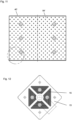
Figure 12 shows a detail view of an upper clamping plate. -
Figure 13 shows a detail view of a lower clamping plate. -
Figure 14 shows a structured surface with two-dimensional undulations. -
Figure 15 shows a structured surface with one-dimensional undulations including at least one cutting tooth. -
Figures 16 and17 show an alternative embodiment of a building structure. -
Figures 1 to 5 show successive steps during the installation of a building structure. In a first step, a timber column, which intended to be thelower column 10 of the structure, is supplied. A metal lower clampingplate 15 is attached to a face of thelower column 10, which face is intended to be an upper face of thelower column 10. Atension rod 50, particularly consisting of steel, is anchored within thelower column 10, so that thetension rod 50 protrudes from thelower column 10 through thelower clamping plate 15. Attaching the clampingplate 15 and/or the tension rod is 50 preferably done off-site, before shipment of thelower clamping plate 15 to the construction site. Thelower column 10 is brought into a vertical position, with the clampingplate 15 and thetension rod 50 located on top of the lower column. The resulting configuration is shown infigure 1 . - As shown in
figures 2 and 3 , a first floor slab 30', asecond floor slab 30", a third floor slab 30'", and a fourth floor slab 30ʺʺ are then provided. The first floor slab 30' includes a first timber panel 31'. The first floor slab 30' further includes a first clamping element 40', consisting of steel, which is attached to the first timber panel 31'. In analogy, thesecond floor slab 30" comprises asecond timber panel 31" and asecond clamping element 40", consisting of steel, which is attached to thesecond timber panel 31", and thethird floor slab 30‴ comprises athird timber panel 31‴ and a third clamping element 40'", consisting of steel, which is attached to thethird timber panel 31‴, and the fourth floor slab 30ʺʺ comprises afourth timber panel 31"" and a fourth clamping element 40ʺʺ, consisting of steel, which is attached to the fourth timber panel 31ʺʺ. - The
floor slabs 30', 30", 30'", 30"" are positioned so that therespective clamping elements 40', 40", 40‴, 40ʺʺ rest on thelower clamping plate 15 and therefore, indirectly, on thelower column 10. The resulting configuration is shown infigure 3 . As shown in particular infigure 6 , protruding centring pins 99 can be provided on thelower clamping plate 15, which can secure thefloor slabs 30', 30", 30'", 30"" in this phase by engaging therespective clamping elements 40', 40", 40‴, 40ʺʺ. - An
upper clamping plate 25 is then placed on therespective clamping elements 40', 40", 40'", 40"". Theupper clamping plate 25 is provided with a hole that receives thetension rod 50 as theupper clamping plate 25 is placed on therespective clamping elements 40', 40", 40'", 40"", so that thetension rod 50 passes through theupper clamping plate 25 and projects therefrom. A hold-downnut 59 is then screwingly placed on thetension rod 50 and tightened thereon, whilst acting against theupper clamping plate 25, thereby clamping theclamping elements 40', 40", 40'", 40"" between theupper clamping plate 25 on one side and thelower clamping plate 15 and thelower column 10 on the other side. The resulting configuration is shown infigure 4 . - An
upper column 20 is then provided and placed (in aligned relationship with the lower column 10) on theupper clamping plate 25. Theupper column 20 then rests, via theupper clamping plate 25, on theclamping elements 40', 40", 40'", 40"". Accordingly, the clampingelements 40', 40", 40'", 40"" are thus clamped between thelower column 10 and theupper column 20. In order to compensate tolerances, hardened mortar might be provided adjacent to at least one of the clampingelements 40', 40", 40'", 40"". - The
upper column 20 has an opening that receives thetension rod 50 as theupper column 20 is positioned on theupper clamping plate 25. A ratchet mechanism 90 (shown schematically infigure 5 only), might be provided on thetension rod 50 or/and in theupper column 20 to anchor thetension rod 50 within theupper column 20 for transferring tensile loads between thetension rod 50 and theupper column 20. - The resulting building structure is shown in
figure 5 , and, in exploded view, infigure 6 . - In the following text, the
floor slabs 30', 30", 30'", 30ʺʺ are described in greater detail. In this connection, it is noted that thesecond floor slab 30", the third floor slab 30'", and the fourth floor slab 30ʺʺ are realized in analogy to the first floor slab 30', i.e. the design and the materials are analogous. Therefore, and for the sake of brevity, the following explanations refer to the first floor slab 30' only. However, unless indicated otherwise, features mentioned in connection with the first floor slab 30' can apply to the remainingflow slabs 30", 30'", 30ʺʺ in analogous manner. - The first timber panel 31' of the first floor slab 30' is generally plate-shaped and has two flat main surfaces (which are the upper and lower surfaces in
figures 2 to 6 ), which main surfaces are generally parallel to one another. The first timber panel 31' moreover has a lateral surface that extends between the two main surfaces. The first clamping element 40' is located in front of the lateral surface of the first timber panel 31', namely in front of an edge region of the lateral surface of the first timber panel 31', and it is connected to the first timber panel 31' on the lateral surface of the first timber panel 31', namely by means of screws 88' that extend through the first clamping element 40' into the first timber panel 31' at the lateral surface of the first timber panel 31'. - The first clamping element 40' has a structured panel contact surface 84' that directly contacts the first timber panel 31', namely the lateral surface of the first timber panel 31'. In the shown embodiment, the structured panel contact surface 84' has a surface structure including a plurality of pins. The screws 88' press the structured panel contact surface 84' onto the first timber panel 31', thereby providing a shear load transfer path.
- The first clamping element 40' is a steel element. It is wedge shaped so as to form an edge of the first floor slab 30'. In particular, the first clamping element 40' tapers with increasing distance from the first timber panel 31'.
- The first clamping element 40' comprises an upper clamping surface 82', which in intended use faces the
upper column 20 and theupper clamping plate 25, and which is intended for engaging theupper clamping plate 25. The first clamping element 40' furthermore comprises a lower clamping surface 81', which in intended use faces thelower column 10 and thelower clamping plate 15, and which is intended to engage thelower clamping plate 15. Both the upper clamping surface 82' and the lower clamping surface 81' are structured. Possible structures might include two dimensional undulations, such as shown infigure 14 , or one-dimensional undulations, optionally including at least one cutting tooth, as shown infigure 15 . -
Figure 12 shows an embodiment of alower clamping plate 15. Thelower clamping plate 15 has anupper contact surface 16 intended for contacting, preferably for directly contacting, the clampingelements 40', 40", 40'", 40"". Theupper contact surface 16 is structured. Possible structures might include two dimensional undulations, such as shown infigure 14 , or one-dimensional undulations, optionally including at least one cutting tooth, as shown infigure 15 . -
Figure 13 shows an embodiment of anupper clamping plate 25. Theupper clamping plate 25 has alower contact surface 26 intended for contacting, preferably for directly contacting (alternatively for indirectly contacting, see embodiment offigures 16 and17 ), the clampingelements 40', 40", 40'", 40"". Thelower contact surface 26 is structured. Possible structures might include two dimensional undulations, such as shown infigure 14 , or one-dimensional undulations, optionally including at least one cutting tooth, as shown infigure 15 . -
Figures 16 and17 show an alternative embodiment of a building structure. The embodiment offigures 16 and17 and the previous embodiment share a common basic concept. Therefore, in the following, focus will be on the differentiating features, whereas reference is made to the description above for the remaining features. Unless indicated otherwise, the description above applies mutatis mutandis to the embodiment offigures 16 and17 . - In particular, the embodiment of
figures 16 and17 differs from the previous embodiment in that the first floor slab 30' includes an additional lateral-force transmittal plate 39', which is fixed, preferably screwingly fixed, to the first timber panel 31', namely to the upper main surface thereof. This lateral-force transmittal plate 39' protrudes between the clamping element 40' and theupper clamping plate 25, and is in direct contact with both the clamping element 40' and theupper clamping plate 25. The clamping element 40' is again clamped between theupper column 20 and thelower column 10, namely via the additional lateral force transmittal plate 39', i.e. the lateral force transmittal plate 39' is included in the vertical clamping force path. Once again, the remainingfloor slabs 30", 30‴, 30ʺʺ, if applicable, can be configured and arranged in analogy to the first floor slab 30'.
Claims (15)
- Building structure comprising- a first floor slab (30') comprising a first timber panel (31'),- a second floor slab (30") comprising a second timber panel (31"),- a timber lower column (10), and- a timber upper column (20), which is arranged above the lower column (10), and which is aligned with the lower column (10),
characterized in that- the first floor slab (30') comprises a metal first clamping element (40'), wherein the first clamping element (40') is attached to the first timber panel (31'), and- the second floor slab (30") comprises a metal second clamping element (40"), wherein the second clamping element (40") is attached to the second timber panel (31"),- wherein the first clamping element (40') and the second clamping element (40") are clamped between the upper column (20) and the lower column (10). - Building structure according to claim 1,
characterized in that- the first timber panel (31') has two flat main surfaces, which are generally parallel to one another, and a lateral surface that extends between the two main surfaces, and- the second timber panel (31") has two flat main surfaces, which are generally parallel to one another, and a lateral surface that extends between the two main surfaces,- wherein the first clamping element (40') is arranged in front of the lateral surface of the first timber panel (31'), and- wherein the second clamping element (40") is arranged in front of the lateral surface of the second timber panel (31"). - Building structure according to claim 2,
characterized in thatthe first clamping element (40') has a first structured panel contact surface (84') that contacts the lateral surface of the first timber panel (31'), andthe second clamping element (40") has a second structured panel contact surface that contacts the lateral surface of the second timber panel (31"). - Building structure according to any of claims 2 or 3,
characterized in thatthe first clamping element (40') is attached to the first timber panel (31') at the lateral surface of the first timber panel (31'), namely by at least one screw (88') extending through the first clamping element (40') into the first timber panel (31'), andthe second clamping element (40") is attached to the second timber panel (31") at the lateral surface of the second timber panel (31"), namely by at least one screw extending through the second clamping element (40") into the second timber panel (31"). - Building structure according to any of claims 2 to 4,
characterized in thatthe first clamping element (40') is arranged in front of an edge region of the lateral surface of the first timber panel (31'), andthe second clamping element (40") is arranged in front of an edge region of the lateral surface of the second timber panel (31"). - Building structure according to any of the preceding claims,
characterized in thatthe first clamping element (40') is wedge shaped so as to form an edge, andthe second clamping element (40") is wedge shaped so as to form an edge. - Building structure according to any of the preceding claims,
characterized in thatthe first clamping element (40') is a steel element, andthe second clamping element (40") is a steel element. - Building structure according to any of the preceding claims,
characterized in thatthe first clamping element (40') comprises an upper clamping surface (82') facing the upper column (20) and a lower clamping surface (81') facing the lower column (10), wherein at least one of the upper clamping surface (82') and the lower clamping surface (81') of the first clamping element (40') is structured, andthe second clamping element (40") comprises an upper clamping surface facing the upper column (20) and a lower clamping surface facing the lower column (10), wherein at least one of the upper clamping surface and the lower clamping surface of the second clamping element (40") is structured. - Building structure according to any of the preceding claims,
characterized in that- the first clamping element (40'), at least partly, projects between the upper column (20) and the lower column (10), and- the second clamping element (40"), at least partly, projects between the upper column (20) and the lower column (10). - Building structure according to any of the preceding claims,
characterized in that- it further comprises a metal upper clamping plate (25), which contacts the upper column (20) on an upper contact surface of the upper clamping plate (25), and which contacts the first and second clamping elements (40', 40") at a lower contact surface (26) of upper clamping plate (25), and- it further comprises a metal lower clamping plate (15), which contacts the lower column (10) on a lower contact surface of the lower clamping plate (15), and which contacts the first and second clamping elements (40', 40") at an upper contact surface (16) of the lower clamping plate (15). - Building structure according to any of the preceding claims,
characterized in that
it further comprises a metal tension rod (50), which is anchored both in the upper column (20) and in the lower column (10). - Building structure according to claim 11,
characterized in that- the tension rod (50) is anchored in the lower column (10) by means of a glued connection, and- the tension rod (50) is anchored in the upper column (20) by means of a ratchet mechanism (90). - Building structure according to any of claims 11 or 12,
characterized in that
the first clamping element (40') and the second clamping element (40") surround the tension rod (50). - Building structure according to any of claims 11 to 13,
characterized in that
it further comprises a hold-down nut (59), which is screwed onto the tension rod (50) so as to tension the first and second clamping elements (40', 40") against the lower column (10). - Building structure according to any of the preceding claims, further comprising- a third floor slab (30‴) comprising a third timber panel (31‴)- a fourth floor slab (30ʺʺ) comprising a fourth timber panel (31ʺʺ),- wherein the third floor slab (30‴) comprises a metal third clamping element (40‴), wherein the third clamping element (40‴) is attached to the third timber panel (31‴),- wherein the fourth floor slab (30ʺʺ) comprises a metal fourth clamping element (40ʺʺ), wherein the fourth clamping element (40"") is attached to the fourth timber panel (31""), and- wherein the third clamping element (40‴") and the fourth clamping element (40"") are clamped between the upper column (20) and the lower column (10).
Priority Applications (4)
| Application Number | Priority Date | Filing Date | Title |
|---|---|---|---|
| EP23173611.7A EP4464852A1 (en) | 2023-05-16 | 2023-05-16 | Timber building structure |
| AU2024271922A AU2024271922A1 (en) | 2023-05-16 | 2024-05-02 | Timber building structure |
| EP24724132.6A EP4713542A1 (en) | 2023-05-16 | 2024-05-02 | Timber building structure |
| PCT/EP2024/062081 WO2024235651A1 (en) | 2023-05-16 | 2024-05-02 | Timber building structure |
Applications Claiming Priority (1)
| Application Number | Priority Date | Filing Date | Title |
|---|---|---|---|
| EP23173611.7A EP4464852A1 (en) | 2023-05-16 | 2023-05-16 | Timber building structure |
Publications (1)
| Publication Number | Publication Date |
|---|---|
| EP4464852A1 true EP4464852A1 (en) | 2024-11-20 |
Family
ID=86386845
Family Applications (2)
| Application Number | Title | Priority Date | Filing Date |
|---|---|---|---|
| EP23173611.7A Withdrawn EP4464852A1 (en) | 2023-05-16 | 2023-05-16 | Timber building structure |
| EP24724132.6A Pending EP4713542A1 (en) | 2023-05-16 | 2024-05-02 | Timber building structure |
Family Applications After (1)
| Application Number | Title | Priority Date | Filing Date |
|---|---|---|---|
| EP24724132.6A Pending EP4713542A1 (en) | 2023-05-16 | 2024-05-02 | Timber building structure |
Country Status (3)
| Country | Link |
|---|---|
| EP (2) | EP4464852A1 (en) |
| AU (1) | AU2024271922A1 (en) |
| WO (1) | WO2024235651A1 (en) |
Citations (29)
| Publication number | Priority date | Publication date | Assignee | Title |
|---|---|---|---|---|
| FR2418319A1 (en) | 1978-02-24 | 1979-09-21 | Bosson Jacques | Stanchion support for variable height floor decking - has platform that supports and locks each floor deck panel |
| US4330970A (en) * | 1979-10-23 | 1982-05-25 | Copreal S.A. | Building structure and steel parts for same |
| US4930270A (en) | 1986-07-01 | 1990-06-05 | Aldo Bevacqua | Building systems |
| DE3903770A1 (en) | 1989-02-09 | 1990-10-11 | Erich Raatz | Connection-type support for erecting container housings and/or prefabricated three-dimensional bodies |
| US4996804A (en) | 1989-05-17 | 1991-03-05 | Naka Corporation | Device and structure for supporting floor panels |
| DE4115239A1 (en) | 1991-02-12 | 1992-08-13 | Goldbach Gmbh Holz | Floor constructed from panels supported on pillars - has screw threads to provide height adjustment |
| CA2221951A1 (en) | 1997-11-24 | 1999-05-24 | Hugh A. Dantzer | Decking system |
| DE19859574A1 (en) * | 1998-12-22 | 2000-08-17 | Konstruktion Holz Werk Khw Seu | Construction connection unit for e.g. house has skeleton construction unit with a number of cross-struts and vertical cross-bars |
| DE19918797A1 (en) | 1999-04-26 | 2000-11-09 | Wolfgang Hoppe | Modular wall panel has grip edges for assembling with similar panels and without a separate support frame |
| EP2075383A2 (en) | 2007-12-28 | 2009-07-01 | Uwe Bäßler | Device for combining components |
| EP2196597A1 (en) | 2008-12-12 | 2010-06-16 | D-EFFE S.r.l. Società Unipersonale | Supporting column for superelevated floors and production process |
| JP2011163016A (en) | 2010-02-10 | 2011-08-25 | Fukuvi Chemical Industry Co Ltd | Floor post for supporting intersection point |
| WO2011123873A2 (en) | 2010-04-09 | 2011-10-13 | Lb Engineering Gmbh | Connecting element for prefabricated elements |
| CN103334499A (en) * | 2013-07-08 | 2013-10-02 | 山东中通钢构建筑股份有限公司 | Beam column node connection device |
| EP2687645A1 (en) | 2012-07-19 | 2014-01-22 | Rotho Blaas srl GmbH | Joint element for components, in particular panels and supports |
| CA2839486A1 (en) | 2014-01-14 | 2015-07-14 | Rotho Blaas Srl Gmbh | Element for the connection of building components, particularly panels and beams |
| US20150198188A1 (en) | 2014-01-16 | 2015-07-16 | Rotho Blaas Srl Gmbh | Element for the connection of building components, particularly panels and beams |
| EP2687651B1 (en) | 2012-07-19 | 2017-08-30 | Rotho Blaas srl GmbH | Method for the adjustment and/or attachment of wood panels or beams and a structure constructed using this method |
| US20170260750A1 (en) | 2014-12-09 | 2017-09-14 | Daniel Essig | Roof paver locking system and methods for installing pavers |
| CN107654009A (en) | 2017-11-07 | 2018-02-02 | 南京林业大学 | A kind of pin and CLT wood floor attachment structures |
| CN108086556A (en) | 2018-01-31 | 2018-05-29 | 江苏保力自动化科技有限公司 | Integrated light girder truss composite floor and its flange plate type connection structure |
| JP2018131751A (en) | 2017-02-13 | 2018-08-23 | 株式会社竹中工務店 | Column support structure |
| CN109083270A (en) | 2018-09-14 | 2018-12-25 | 四川恒达兴铁科技有限公司 | A kind of assembled architecture framework |
| US20180371741A1 (en) | 2015-12-02 | 2018-12-27 | Universitat Innsbruck | Connecting Device for Mounting a Wooden Construction Element |
| US20190186121A1 (en) | 2016-07-13 | 2019-06-20 | Universität Innsbruck | Connection system |
| US20200024852A1 (en) | 2017-03-01 | 2020-01-23 | Matteo CASPRINI | A modular floating screed with incorporated heating elements |
| CN113445636A (en) | 2021-08-11 | 2021-09-28 | 扬州工业职业技术学院 | Bamboo-wood column-wood floor composite structure |
| US20220275635A1 (en) | 2021-02-26 | 2022-09-01 | Mercer Mass Timber Llc | Cross-laminated timber and cold formed steel connector and system |
| WO2023277706A1 (en) | 2021-06-28 | 2023-01-05 | Holmes Solutions Limited Partnership | A coupling system, coupler tools and methods of use thereof |
-
2023
- 2023-05-16 EP EP23173611.7A patent/EP4464852A1/en not_active Withdrawn
-
2024
- 2024-05-02 EP EP24724132.6A patent/EP4713542A1/en active Pending
- 2024-05-02 AU AU2024271922A patent/AU2024271922A1/en active Pending
- 2024-05-02 WO PCT/EP2024/062081 patent/WO2024235651A1/en not_active Ceased
Patent Citations (29)
| Publication number | Priority date | Publication date | Assignee | Title |
|---|---|---|---|---|
| FR2418319A1 (en) | 1978-02-24 | 1979-09-21 | Bosson Jacques | Stanchion support for variable height floor decking - has platform that supports and locks each floor deck panel |
| US4330970A (en) * | 1979-10-23 | 1982-05-25 | Copreal S.A. | Building structure and steel parts for same |
| US4930270A (en) | 1986-07-01 | 1990-06-05 | Aldo Bevacqua | Building systems |
| DE3903770A1 (en) | 1989-02-09 | 1990-10-11 | Erich Raatz | Connection-type support for erecting container housings and/or prefabricated three-dimensional bodies |
| US4996804A (en) | 1989-05-17 | 1991-03-05 | Naka Corporation | Device and structure for supporting floor panels |
| DE4115239A1 (en) | 1991-02-12 | 1992-08-13 | Goldbach Gmbh Holz | Floor constructed from panels supported on pillars - has screw threads to provide height adjustment |
| CA2221951A1 (en) | 1997-11-24 | 1999-05-24 | Hugh A. Dantzer | Decking system |
| DE19859574A1 (en) * | 1998-12-22 | 2000-08-17 | Konstruktion Holz Werk Khw Seu | Construction connection unit for e.g. house has skeleton construction unit with a number of cross-struts and vertical cross-bars |
| DE19918797A1 (en) | 1999-04-26 | 2000-11-09 | Wolfgang Hoppe | Modular wall panel has grip edges for assembling with similar panels and without a separate support frame |
| EP2075383A2 (en) | 2007-12-28 | 2009-07-01 | Uwe Bäßler | Device for combining components |
| EP2196597A1 (en) | 2008-12-12 | 2010-06-16 | D-EFFE S.r.l. Società Unipersonale | Supporting column for superelevated floors and production process |
| JP2011163016A (en) | 2010-02-10 | 2011-08-25 | Fukuvi Chemical Industry Co Ltd | Floor post for supporting intersection point |
| WO2011123873A2 (en) | 2010-04-09 | 2011-10-13 | Lb Engineering Gmbh | Connecting element for prefabricated elements |
| EP2687645A1 (en) | 2012-07-19 | 2014-01-22 | Rotho Blaas srl GmbH | Joint element for components, in particular panels and supports |
| EP2687651B1 (en) | 2012-07-19 | 2017-08-30 | Rotho Blaas srl GmbH | Method for the adjustment and/or attachment of wood panels or beams and a structure constructed using this method |
| CN103334499A (en) * | 2013-07-08 | 2013-10-02 | 山东中通钢构建筑股份有限公司 | Beam column node connection device |
| CA2839486A1 (en) | 2014-01-14 | 2015-07-14 | Rotho Blaas Srl Gmbh | Element for the connection of building components, particularly panels and beams |
| US20150198188A1 (en) | 2014-01-16 | 2015-07-16 | Rotho Blaas Srl Gmbh | Element for the connection of building components, particularly panels and beams |
| US20170260750A1 (en) | 2014-12-09 | 2017-09-14 | Daniel Essig | Roof paver locking system and methods for installing pavers |
| US20180371741A1 (en) | 2015-12-02 | 2018-12-27 | Universitat Innsbruck | Connecting Device for Mounting a Wooden Construction Element |
| US20190186121A1 (en) | 2016-07-13 | 2019-06-20 | Universität Innsbruck | Connection system |
| JP2018131751A (en) | 2017-02-13 | 2018-08-23 | 株式会社竹中工務店 | Column support structure |
| US20200024852A1 (en) | 2017-03-01 | 2020-01-23 | Matteo CASPRINI | A modular floating screed with incorporated heating elements |
| CN107654009A (en) | 2017-11-07 | 2018-02-02 | 南京林业大学 | A kind of pin and CLT wood floor attachment structures |
| CN108086556A (en) | 2018-01-31 | 2018-05-29 | 江苏保力自动化科技有限公司 | Integrated light girder truss composite floor and its flange plate type connection structure |
| CN109083270A (en) | 2018-09-14 | 2018-12-25 | 四川恒达兴铁科技有限公司 | A kind of assembled architecture framework |
| US20220275635A1 (en) | 2021-02-26 | 2022-09-01 | Mercer Mass Timber Llc | Cross-laminated timber and cold formed steel connector and system |
| WO2023277706A1 (en) | 2021-06-28 | 2023-01-05 | Holmes Solutions Limited Partnership | A coupling system, coupler tools and methods of use thereof |
| CN113445636A (en) | 2021-08-11 | 2021-09-28 | 扬州工业职业技术学院 | Bamboo-wood column-wood floor composite structure |
Also Published As
| Publication number | Publication date |
|---|---|
| AU2024271922A1 (en) | 2025-10-16 |
| WO2024235651A1 (en) | 2024-11-21 |
| EP4713542A1 (en) | 2026-03-25 |
Similar Documents
| Publication | Publication Date | Title |
|---|---|---|
| CA1325874C (en) | Structural connection system | |
| US7562500B2 (en) | Composite steel joist/composite beam floor system and steel stud wall systems | |
| CA2741013C (en) | Construction frame shear lug | |
| EP3802963B1 (en) | Compression and tension reinforced wall | |
| US7712282B2 (en) | Brace assembly having ductile anchor | |
| US20130019545A1 (en) | Engineered Wood Construction System for High Performance Structures | |
| US12546134B2 (en) | Reinforced tie rod and a building wall using the same | |
| US12281469B2 (en) | Cross-laminated timber and cold-formed steel connector and system | |
| US20220275635A1 (en) | Cross-laminated timber and cold formed steel connector and system | |
| JP7685148B2 (en) | Shear wall panel connection structure | |
| WO2024235651A1 (en) | Timber building structure | |
| CN114575509B (en) | Assembled building beam plate connecting structure and connecting method | |
| JP7457557B2 (en) | Joint structure of wooden shaft members | |
| JPH1181737A (en) | Damping structure of reinforced concrete building and construction method | |
| CN214615054U (en) | Prefabricated module building roof layer structure | |
| JPH06102510B2 (en) | Elevator guide rail device | |
| CN113047451B (en) | Fabricated shear wall dry connection construction method facilitating floor slab reinforcement passing | |
| US12503849B2 (en) | Wall system with infilled cross-laminated timber panel | |
| CN216038044U (en) | Steel beam hoistway elevator guide rail bracket | |
| JP7681242B2 (en) | Shear wall panel connection structure | |
| Pratchett et al. | Issues with residential hold down systems | |
| CN112411893A (en) | Prefabricated modular building roof layer structure and its construction method | |
| JP7356695B2 (en) | wooden building structure | |
| WO2026023122A1 (en) | Building | |
| EP4486959A1 (en) | System and method for suspending a framework structure on a load bearing structure of a building and use of such suspension system |
Legal Events
| Date | Code | Title | Description |
|---|---|---|---|
| PUAI | Public reference made under article 153(3) epc to a published international application that has entered the european phase |
Free format text: ORIGINAL CODE: 0009012 |
|
| STAA | Information on the status of an ep patent application or granted ep patent |
Free format text: STATUS: THE APPLICATION HAS BEEN PUBLISHED |
|
| AK | Designated contracting states |
Kind code of ref document: A1 Designated state(s): AL AT BE BG CH CY CZ DE DK EE ES FI FR GB GR HR HU IE IS IT LI LT LU LV MC ME MK MT NL NO PL PT RO RS SE SI SK SM TR |
|
| STAA | Information on the status of an ep patent application or granted ep patent |
Free format text: STATUS: THE APPLICATION IS DEEMED TO BE WITHDRAWN |
|
| 18D | Application deemed to be withdrawn |
Effective date: 20250521 |