EP4464461A2 - Angetriebener einrastbarer drehmomentschlüssel - Google Patents
Angetriebener einrastbarer drehmomentschlüssel Download PDFInfo
- Publication number
- EP4464461A2 EP4464461A2 EP24194640.9A EP24194640A EP4464461A2 EP 4464461 A2 EP4464461 A2 EP 4464461A2 EP 24194640 A EP24194640 A EP 24194640A EP 4464461 A2 EP4464461 A2 EP 4464461A2
- Authority
- EP
- European Patent Office
- Prior art keywords
- power tool
- torque
- fastener
- location
- electronic processor
- Prior art date
- Legal status (The legal status is an assumption and is not a legal conclusion. Google has not performed a legal analysis and makes no representation as to the accuracy of the status listed.)
- Pending
Links
Images


Classifications
-
- B—PERFORMING OPERATIONS; TRANSPORTING
- B25—HAND TOOLS; PORTABLE POWER-DRIVEN TOOLS; MANIPULATORS
- B25B—TOOLS OR BENCH DEVICES NOT OTHERWISE PROVIDED FOR, FOR FASTENING, CONNECTING, DISENGAGING OR HOLDING
- B25B21/00—Portable power-driven screw or nut setting or loosening tools; Attachments for drilling apparatus serving the same purpose
- B25B21/004—Portable power-driven screw or nut setting or loosening tools; Attachments for drilling apparatus serving the same purpose of the ratchet type
-
- B—PERFORMING OPERATIONS; TRANSPORTING
- B25—HAND TOOLS; PORTABLE POWER-DRIVEN TOOLS; MANIPULATORS
- B25B—TOOLS OR BENCH DEVICES NOT OTHERWISE PROVIDED FOR, FOR FASTENING, CONNECTING, DISENGAGING OR HOLDING
- B25B13/00—Spanners; Wrenches
- B25B13/46—Spanners; Wrenches of the ratchet type, for providing a free return stroke of the handle
- B25B13/461—Spanners; Wrenches of the ratchet type, for providing a free return stroke of the handle with concentric driving and driven member
- B25B13/462—Spanners; Wrenches of the ratchet type, for providing a free return stroke of the handle with concentric driving and driven member the ratchet parts engaging in a direction radial to the tool operating axis
- B25B13/465—Spanners; Wrenches of the ratchet type, for providing a free return stroke of the handle with concentric driving and driven member the ratchet parts engaging in a direction radial to the tool operating axis a pawl engaging an internally toothed ring
-
- B—PERFORMING OPERATIONS; TRANSPORTING
- B25—HAND TOOLS; PORTABLE POWER-DRIVEN TOOLS; MANIPULATORS
- B25B—TOOLS OR BENCH DEVICES NOT OTHERWISE PROVIDED FOR, FOR FASTENING, CONNECTING, DISENGAGING OR HOLDING
- B25B23/00—Details of, or accessories for, spanners, wrenches, screwdrivers
- B25B23/14—Arrangement of torque limiters or torque indicators in wrenches or screwdrivers
- B25B23/147—Arrangement of torque limiters or torque indicators in wrenches or screwdrivers specially adapted for electrically operated wrenches or screwdrivers
-
- B—PERFORMING OPERATIONS; TRANSPORTING
- B25—HAND TOOLS; PORTABLE POWER-DRIVEN TOOLS; MANIPULATORS
- B25F—COMBINATION OR MULTI-PURPOSE TOOLS NOT OTHERWISE PROVIDED FOR; DETAILS OR COMPONENTS OF PORTABLE POWER-DRIVEN TOOLS NOT PARTICULARLY RELATED TO THE OPERATIONS PERFORMED AND NOT OTHERWISE PROVIDED FOR
- B25F5/00—Details or components of portable power-driven tools not particularly related to the operations performed and not otherwise provided for
Definitions
- the present invention relates to a power tool, and more particularly to a powered ratcheting torque wrench.
- Powered ratcheting wrenches typically include a motor, a drive assembly driven by the motor, and a rotating output for applying torque to a fastener.
- the motor may be powered by electricity (e.g., a DC or AC source) or pressurized air.
- the invention provides a power tool including a motor having a motor drive shaft, a drive assembly coupled to the motor drive shaft and driven by the motor, an output assembly coupled to the drive assembly and having an output member that receives torque from the drive assembly, causing the output member to rotate about an axis, and a transducer assembly disposed between the motor and the output assembly to measure the amount of torque applied through the output member, when the motor is deactivated, in response to the power tool being manually rotated about the axis.
- the invention provides a ratcheting torque wrench including a housing, a battery pack removably coupled to the housing, a motor that receives power from the battery pack when activated.
- the motor has a motor drive shaft rotatable about a first axis.
- the torque wrench further includes a drive assembly coupled to the motor drive shaft and driven by the motor when activated, an output assembly coupled to the drive assembly and having and an output member that receives torque from the drive assembly, causing the output member to rotate about a second axis perpendicular to the first axis, and a transducer assembly disposed between the motor and the output assembly to measure the amount of torque applied through the output member, when the motor is deactivated, using power received from the battery pack in response to the power tool being manually rotated about the second axis.
- the invention provides a method of determining peak torque for fastening operations of a power tool.
- the method includes detecting that the power tool is performing a fastening operation for a first fastener and determining, using a torque sensor of the power tool, torque values for the fastening operation.
- the method also includes recording, using an electronic processor of the power tool, the torque values for the fastening operation to generate recorded torque values for the fastening operation and determining a peak torque value from the recorded torque values, wherein the peak torque value corresponds to the fastening operation.
- the method further includes providing an indication of the peak torque value.
- the invention provides a power tool for determining peak torque for fastening operations.
- the power tool includes a motor driving a tool bit, a torque sensor determining an output torque of the tool bit, a position sensor configured to determine a relative position of the power tool, a transmitter configured to transmit information from the power tool to a remote device, and an electronic processor coupled to the torque sensor, the position sensor, and the transmitter.
- the electronic processor is configured to determine, using the position sensor, that the power tool is performing a fastening operation for a first fastener and determine, using the torque sensor, torque values for the fastening operation.
- the electronic processor is also configured to record the torque values for the fastening operation to generate recorded torque values for the fastening operation and determine a peak torque value from the recorded torque values, wherein the peak torque value corresponds to the fastening operation.
- the electronic processor is further configured to provide an indication of the peak torque value.
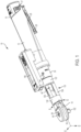
- FIG. 1 illustrates a battery-powered hand-held ratcheting torque wrench 10.
- the wrench 10 includes a main housing 12 and a battery pack 16 attached to the main housing 12.
- the battery pack 16 is a removable and rechargeable 12-volt battery pack and includes three (3) Lithium-ion battery cells.
- the battery pack may include fewer or more battery cells such that the battery pack is a 14.4-volt battery pack, an 18-volt battery pack, or the like.
- the battery cells may have chemistries other than Lithium-ion such as, for example, Nickel Cadmium, Nickel Metal-Hydride, or the like.
- the battery pack 16 is inserted into a cavity in the main housing 12 in the axial direction of axis A ( FIG. 5 ) and snaps into connection with the main housing 12.
- the battery pack 16 includes a latch 17 ( FIG. 1 ), which can be depressed to release the battery pack 16 from the wrench 10.
- the wrench 10 includes a cord and is powered by a remote source of power, such as an AC utility source connected to the cord.
- the wrench 10 may be a pneumatic tool powered by pressurized air flow through a rotary air vane motor, not shown.
- the wrench 10 instead of the battery pack 16 and electric motor 18, the wrench 10 includes a rotary air vane motor (not shown) and a connector (not shown) for receiving pressurized air.
- other power sources may be employed.
- the wrench 10 includes a motor 18, a motor drive shaft 20 extending from the motor 18 and centered about the axis A, and a drive assembly 22 coupled to the drive shaft 20 for driving an output assembly 24.
- the output assembly 24 defines a central axis B substantially perpendicular to axis A, and will be described in greater detail below.
- the wrench 10 also includes an actuator, such as a paddle 28, for actuating an electrical switch 26 to electrically connect the motor 18 to the battery pack 16.
- the drive assembly 22 includes a planetary geartrain 34 positioned between the motor 18 and the output assembly 24, and located within a gear housing 36.
- the planetary geartrain 34 includes a sun gear 38 coupled for co-rotation with the motor drive shaft 20, a planet carrier 40, three planet gears 42 rotatably supported upon the carrier 40, and a ring gear 44 fixed within the gear housing 36. Accordingly, torque received from the motor 18 is increased by the planetary geartrain 34, which also provides a reduced rotational output speed compared to the rotational speed of the motor drive shaft 20.
- the drive assembly 22 also includes a multi-piece crankshaft 46 having an eccentric member 48, which is described in further detail below, a drive bushing 50 on the eccentric member 48, and two needle bearings 52 supporting the crankshaft 46 for rotation in the gear housing 36 and a head 14, respectively, which is coupled to the gear housing 36.
- the output assembly 24 includes a yoke 54 and an anvil 56 rotatably supporting the yoke 54 within the head 14.
- the anvil 56 includes an output member 102 ( FIG. 1 ), such as a square head for receiving sockets.
- the output assembly 24 also includes a pawl 58 pivotably coupled to the yoke 54 by a pin 64 and a shift knob 60.
- the yoke 54, anvil 56, and shift knob 60 are centered along the axis B.
- the output assembly 24 also includes a spring 66 and spring cap 68 supported for co-rotation with the shift knob 60.
- the shift knob 60 is rotated between two positions, causing the pawl 58 to pivot about the pin 64 (through sliding contact with the spring cap 68) between a first position where torque is transferred to the anvil 56 (by the yoke 54) in a clockwise direction of rotation, and a second position where torque is transferred to the anvil 56 in a counterclockwise direction of rotation.
- a combination of at least the yoke 54 and anvil 56 may comprise a ratchet mechanism.
- the output assembly 24 further includes a detent (e.g., a ball 70) and spring 72 biasing the ball 70 outward for retaining sockets on the output member 102, as shown in FIG. 5 .
- the head 14 is formed from steel as one piece and includes a cylindrical portion 84, an adjacent shoulder portion 86, and spaced first and second ears 90, 92 between which the yoke 54 is received.
- the first ear 90 includes a first aperture 94 and the second ear 92 includes a second aperture 96.
- the first and second apertures 94, 96 are centered about the axis B.
- the yoke 54 is received between the first and second ears 90, 92 in a direction perpendicular to axis B.
- the anvil 56 is received in the first and second apertures 94, 96 and the shift knob 60 is received in the first aperture 94.
- the first ear 90 includes an outer surface 100 facing away from the second ear 92.
- the shift knob 60 is fully recessed within the first ear 90 such that the shift knob 60 does not cross a plane defined by the outer surface 100 and is positioned entirely on a side of the outer surface 100 on which the output member 102 is located, as can be seen by the cross section views of FIG. 6 .
- the outer surface 100 is opposite and facing away from the output member 102.
- the output assembly 24 of the wrench 10 includes a single-pawl ratchet design.
- the pawl 58 is disposed between the first and second ears 90, 92.
- the yoke 54 is oscillated between a first direction and a second direction about axis B by the eccentric member 48.
- An inner diameter of the yoke 54 defined by an aperture includes teeth 49 ( FIGS. 2 and 6 ) that mate with angled teeth 59 of the pawl 58 when the yoke 54 moves in the first direction.
- the yoke teeth 49 slide with respect to the angled teeth 59 of the pawl 58 when the pawl 58 moves in the second direction opposite the first direction such that only one direction of motion is transferred from the yoke 54 to the output member 102.
- the shift knob 60 cooperates with the spring 66 and the spring cap 68 to orient the pawl 58 with respect to the pin 64 such that the opposite direction of motion is transferred from the yoke 54 to the output member 102 when the shift knob 60 is rotated to a reverse position.
- the output assembly 24 may alternatively include a dual-pawl design.
- the wrench 10 further includes a transducer assembly 118 positioned inline and coaxial with the axis A, the motor 18, and the head 14.
- the transducer assembly 118 detects the torque output by the output member 102 when the wrench 10 is manually rotated about axis B (with the motor 18 deactivated), and indicates to a user (via a display device) when the torque output reaches a pre-defined torque value or torque threshold.
- the wrench 10 may include a light emitting diode (LED) 124 ( FIG. 5 ) for illuminating a workpiece during use of the wrench 10. But, in response to a pre-defined torque value or torque threshold being reached when the wrench 10 is manually rotated about axis B, the LED 124 may flash to signal the user that the pre-defined torque value is reached.
- LED light emitting diode
- the transducer assembly 118 is positioned between and interconnects the head 14 and the gear housing 36.
- the transducer assembly 118 includes a frame 120 defining a first cylindrical mount 122 that receives a portion of the gear housing 36 and that is affixed thereto (e.g., by fastening), which in turn is attached to (or alternatively integral with) the housing 12.
- the frame 120 also includes a second cylindrical mount 130 that receives the cylindrical portion 84 of the head 14 and that is affixed thereto (e.g., by fastening).
- the frame 120 further includes two beams 134 extending between the first and second cylindrical mounts 122, 130.
- a transducer assembly 218, which is otherwise similar to transducer assembly 118 may include a frame that is integrally formed with the head 14 such that the frame of the transducer assembly 218 and the head 14 are a single monolithic component.
- the beams 134 are parallel and offset from the axis A such that an air gap 138 exists between the beams 134.
- the transducer assembly 118 includes one or more sensors (e.g., strain gauges 142) coupled to each of the beams 134 for detecting the strain on each of the beams 134 in response to a bending force or moment applied to the beams 134.
- the strain gauges 142 are electrically connected to a high-level or master controller of the wrench 10 for transmitting respective voltage signals generated by the strain gauges 142 proportional to the magnitude of strain experienced by the respective beams 134, which is indicative of the torque applied to a workpiece (e.g., a fastener) by the output member 102 when the wrench 10 is manually rotated about axis B (with the motor 18 deactivated).
- a workpiece e.g., a fastener
- the transducer assembly 118 may alternatively be formed with fewer or greater than two beams 134 and a corresponding number of strain gauges 142.
- transducer assembly 318 is formed with a single beam 334 and a single strain gauge 342 extending between the first and second cylindrical mounts 322, 330.
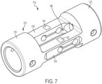
- FIGS. 11 and 12 illustrate yet another transducer assembly 418 usable with the torque wrench 10 of FIG. 1 .
- the transducer assembly 418 includes a frame 420 having two cylindrical mounts 422, 430 and a beam 434 extending therebetween.
- the beam 434 is hollow and has a substantially square cross-sectional shape ( FIG. 12 ).
- the beam 434 includes four walls 434a-d connected together at right angles, with each wall 434a-d having a wall thickness 439 of about one millimeter to about three millimeters. More specifically, the wall thickness 439 of each wall 434a-d is about two millimeters.
- the transducer assembly 418 also includes a strain gauge 442 on each of the walls 434a, 434b on an exterior surface thereof for detecting the strain on the beams 434.
- each of the walls 434a-d may include an associated strain gauge 442. Because the beam 434 is hollow, an air gap 438 exists through which the crankshaft 46 extends.
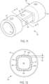
- FIGS. 13 and 14 illustrate yet another transducer assembly 518 usable with the torque wrench 10 of FIG. 1 .
- the transducer assembly 518 includes a frame 520 having two cylindrical mounts 522, 530 and a beam 534 extending therebetween. Similar to the beam 434, the beam 534 is hollow but has a substantially tubular cross-section ( FIG. 14 ) rather than a square cross-section.
- the beam 534 has a wall thickness 539 of about 0.5 millimeters to about 1.5 millimeters. More specifically, the wall thickness 539 is about one millimeter.
- the transducer assembly 518 also includes two strain gauges 542 disposed on the exterior surface of the beam 534 and spaced apart 90 degrees from each other. In other embodiments, the beam 534 may include more than two strain gauges 542 that are spaced apart at various angular intervals. Because the beam 534 is hollow, an air gap 538 exists through which the crankshaft 46 extends.
- the multi-piece crankshaft 46 includes a first shaft 157 having the eccentric member 48 at a front end thereof and a second shaft 158 having a rear end coupled for co-rotation with the carrier 40.
- the first and second shafts 157, 158 are coupled for co-rotation via a universal joint (i.e., U-joint 162).
- a swivel spline or a flexible shaft, or another coupling that permits misalignment between the shafts 157, 158 while also transmitting torque from the shaft 157 to the shaft 158 may be used instead of the U-joint 162.
- the shafts 157, 158 may be integrally formed as a single flexible shaft.
- the U-joint 162 is disposed within the air gap 138 between the two beams 134 of the transducer assembly 118 to permit misalignment between the shafts 157, 158 along the axis A when the beams 134 experience bending.
- the U-joint 162 includes a socket 166 and a pin 170 that is received within the socket 166 such that the pin 170 is allowed to pivot within the socket 166.
- the U-joint 162 permits the first shaft 157 to rotate about a longitudinal axis that is non-collinear with the axis A of the motor drive shaft 20.
- the wrench 10 also includes a display device 146 with which the transducer assembly 118 interfaces (i.e., through the high-level or master controller) to display the numerical torque value output by the output member 102 when the wrench 10 is manually rotated about axis B with the motor 18 deactivated.
- a display device 146 e.g., a display screen
- Such a display device 146 may be situated on the housing 12 and/or the gear housing 18, or may be remotely positioned from the wrench 10 (e.g., a mobile electronic device).
- the wrench 10 would include a transmitter (e.g., using Bluetooth or WiFi transmission protocols, for example) for wirelessly communicating the torque value achieved by the output member 102 to the remote display device.
- the on-board display device 146 indicates the numerical torque value measured by the transducer assembly 118.
- the wrench 10 also includes a visual indicator, such as an LED 150, and an audible indicator, such as a buzzer 154, that may work in conjunction with or separately from the LED 124 to indicate to a user when a pre-defined torque setting is reached.
- a user may also adjust the pre-defined torque settings using buttons 156 provided adjacent the display device 146.
- the user In operation of the wrench 10, the user first sets a pre-defined torque value or setting using the buttons 156 and the feedback provided by the display device 146. Subsequently, the user actuates the paddle 28, which activates the motor 18 to provide rapid bursts of torque to the output member 102, causing it to rotate, as the yoke 54 pivotably reciprocates about the axis A. In this manner, a fastener (e.g., a bolt or nut) can be quickly driven by the output member 102 to a seated position on a workpiece. After the fastener is seated on the workpiece, the user may release the paddle 28, thereby deactivating the motor 18.
- a fastener e.g., a bolt or nut
- control system of the wrench 10 may be configured to deactivate the motor 18 upon the fastener becoming seated on the workpiece without requiring the user to release the paddle 28.
- the transducer assembly 118 may remain active to measure the torque imparted on the output member 102 and the fastener in response to the wrench 10 being manually rotated about the axis B by the user.
- the output member 102 becomes effectively rotationally locked to the head 14 (and therefore the housing 12) when the anvil 56 and connected pawl 58 back-drive the yoke 58 which, in turn, is unable to further back-drive the eccentric member 48 on the crankshaft 46.
- the controller of the wrench which may be implemented as an electronic processor 1025 ( FIG. 15 ), monitors the signals output by the strain gauges 126, interpolates the signals to a torque value, compares the measured torque to one or more pre-defined values or settings input by the user, and activates the LED 150 (and/or the LED 124 to vary a lighting pattern of the workpiece) to signal the user of the wrench 10 that a final desired torque value has been applied to a fastener.
- the wrench 10 may also activate the buzzer 154 when the final desired torque value has been applied to a fastener to provide an audible signal to the user.
- FIG. 15 is a block diagram of one embodiment of a power tool 1000 communicating with a remote device 1005.
- the power tool 1000 is the ratcheting torque-wrench 10 described above.
- the power tool 1000 may be a different power tool such as a drill/driver, a hammer drill, or the like.
- the remote device 1005 is, for example, a smart telephone, a laptop computer, a tablet computer, a desktop computer, or the like.
- the power tool 1000 includes a power supply 1010, a motor 1015, an inverter bridge 1020, an electronic processor 1025, a torque sensor 1030, a position sensor 1035, and a transceiver 1040.
- the power tool 1000 further includes the above-mentioned LED 124, strain gauges 142, display device 146, buzzer 154, and buttons 156, which are electrically connected to the electronic processor 1025 and operate as discussed above.
- the remote device 1005 includes a device electronic processor 1055, a device memory 1060, a device transceiver 1065, and a device input/output interface 1070.
- FIG. 15 illustrates only one example embodiment of a power tool 1000 and a remote device 1005.
- the power tool 1000 and/or the remote device 1005 may include more of fewer components and may perform functions other than those explicitly described herein.
- the power supply 1010 may be a battery pack (e.g., battery pack 16), an AC utility source, or the like.
- the motor 1015 is, for example, an electric brushless DC motor (such as, the electric motor 18) controlled by the electronic processor 1025 through the inverter bridge 1020.
- the electronic processor 1025 is implemented as a microprocessor with separate memory. In other embodiments, the electronic processor 1025 may be implemented as a microcontroller (with memory on the same chip). In other embodiments, the electronic processor 1025 may be implemented using multiple processors. In addition, the electronic processor 1025 may be implemented partially or entirely as, for example, a field-programmable gate array (FPGA), an applications specific integrated circuit (ASIC), and the like and a memory may not be needed or may be modified accordingly.
- the device electronic processor 1055 may be implemented in various ways including ways that are similar to those described above with respect to electronic processor 1025.
- the device memory 1060 includes non-transitory, computer-readable memory that stores instructions that are received and executed by the device electronic processor 1055 to carry out the functionality of the remote device 1005 described herein.
- the device memory 1060 may include, for example a program storage area and a data storage area.
- the program storage area and the data storage area may include combinations of different types of memory, such as read-only memory and random-access memory.
- the transceiver 1040 enables wired or wireless communication between the power tool 1000 and the remote device 1005.
- the transceiver 1040 is a transceiver unit including separate transmitting and receiving components, for example, a transmitter and a receiver.
- the device transceiver 1065 enables wired or wireless communication between the remote device 1005 and the power tool 1000.
- the device transceiver 1065 is a transceiver unit including separate transmitting and receiving components, for example, a transmitter and a receiver.
- the device input/output interface 1070 may include one or more input mechanisms (for example, a touch pad, a keypad, a button, a knob, and the like), one or more output mechanisms (for example, a display, a speaker, and the like), or a combination thereof, or a combined input and output mechanism such as a touch screen.
- input mechanisms for example, a touch pad, a keypad, a button, a knob, and the like
- output mechanisms for example, a display, a speaker, and the like
- a combination thereof for example, a combined input and output mechanism such as a touch screen.
- the torque sensor 1030 is used to measure an output torque of the power tool 1000.
- the torque sensor 1030 is a current sense resistor (e.g., a current sensor) connected in a current path of the power tool 1000.
- the torque sensor 1030 therefore measures a motor current (which is directly proportional to the output torque) flowing to the motor 1015 and provides an indication of the motor current to the electronic processor 1025.
- the power tool 1000 includes both the torque sensor 1030 providing a current-based torque measurement, and the strain gauges 142 providing a strain-based torque measurement.
- one, but not both, of the torque sensor 1030 and the strain gauges 142 are provided in the power tool 1000 to provide torque measurement data to the electronic processor 1025.
- the position sensor 1035 is used to measure an absolute or relative position of the power tool 1000.
- the position sensor 1035 is an inertial measurement unit including one or more of an accelerometer, a gyroscope, a magnetometer, and the like.
- the position sensor 1035 may determine a position of the power tool 1000 based on a dead reckoning technique. That is, the position sensor 1035 may calculate a position of the power tool 1000 by using a previously determined position, and advancing that position based upon readings from the accelerometer, the gyroscope, the magnetometer, etc.
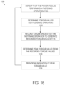
- FIG. 16 is a flowchart illustrating one example method 1100 of determining peak torque for fastening operations of the power tool 1000.
- the method 1100 includes detecting that the power tool 1000 is performing a fastening operation for a first fastener (at block 1105).
- the electronic processor 1025 may determine that the power tool 1000 is performing a fastening operation for a first fastener based on signals from the motor activation switch 26, the position sensor 1035, and/or the torque sensor 1030.
- the electronic processor 1025 may determine that a fastening operation has begun when the electronic processor 1025 receives an activation signal from the motor activation switch 26 in response to depression of the paddle 28 or when the electronic processor 1025 receives a positive torque signal (for example, over an activation threshold) from the torque sensor 1030.
- the electronic processor 1025 may determine that the fastening operation is for the first fastener based on the position of the power tool 1000 as indicated by the position sensor 1035. In some embodiments, the electronic processor 1025 may assign a first position signal received from the position sensor 1035 to the first fastener and store the first position corresponding to the first fastener. That is, the electronic processor 1025 determines, based on an output from the position sensor 1035, that the power tool 1000 is at a first location. The electronic processor 1025 provides an indication that the power tool 1000 is at a first location in response to determining that the power tool 1000 is at the first location. For example, the electronic processor 1025 may provide the indication to the remote device 1005, which displays that the power tool 1000 is fastening a first fastener.
- the electronic processor 1025 determines that the power tool 1000 is at a second location and, in response, provides an indication that the power tool 1000 is at the second location.
- the method 1100 also includes determining, using the torque sensor 1030 of the power tool 1000, torque values for the fastening operation (at block 1110).
- the torque sensor 1030 detects the output torque of the power tool 1000 during the fastening operation.
- the torque sensor 1030 is a current sensor and provides an indication of a motor current to the electronic processor 1025.
- the electronic processor 1025 determines the torque output of the power tool 1000 based on the motor current reading.
- the method 1100 further includes recording, using the electronic processor 1025 of the power tool 1000, the torque values for the fastening operation to generate recorded torque values for the fastening operation (at block 1115).
- the electronic processor 1025 may receive torque values from the torque sensor 1030, for example, every 1 millisecond.
- the electronic processor 1025 may record or store the torque values for the fastening operation corresponding to the first fastener. In some embodiments, as further described below, the torque values may only be recorded when the fastener starts moving (i.e., upon overcoming the static friction).
- the electronic processor 1025 determines that the first fastener has started moving due to the fasting operation based on, for example, signals from the hall-sensor of the motor 1015.
- the recording of the torque values is started after the determination that the first fastener has started moving.
- the torque values are recorded along with an indication of the identity of the fastener determined in block 1105 (e.g., first fastener, second fastener, etc.), of the location of the fastener determined in block 1105 (e.g., first location, second location, etc.), or both.
- the data recorded in block 1115 is stored in a memory of the power tool 1000, in the device memory 1060 of the remote device 1005 (after transmission from the transceiver 1040 to the device transceiver 1065), or both.
- the method 1100 also includes determining a peak torque value from the recorded torque values, wherein the peak torque value corresponds to the fastening operation (at block 1120).
- the electronic processor 1025 determines the peak torque value corresponding to the fastening operation from the recorded torque values for the fastening operation. That is, the electronic processor 1025 may determine that the highest recorded torque value as the peak torque value for the fastening operation.
- the electronic processor 1025 provides the peak torque value to the remote device 1005.
- the device electronic processor 1055 may determine the peak torque value for the fastening operation from the recorded torque values.
- the electronic processor 1025 may provide the torque values for the fastening operation to the remote device 1005 (e.g., as part of block 1115).
- the remote device 1005 may store, in the device memory 1060 or another coupled memory, the torque values received for the fastening operation of the first fastener corresponding to the first fastener.
- the torque values may be stored with the identity of the fastener, the fastener location, or both to correlate the torque values to the fastening operation of the first fastener.
- the device electronic processor 1055 may then determine the peak torque value for the fastening operation from the recorded torque values.
- the method 1100 further includes providing an indication of the peak torque value that was determined in block 1120.
- the electronic processor that performed the determination at block 1120 whether the electronic processor 1025 or the device electronic processor 1055, outputs the peak torque value at block 1125.
- Providing the indication of the peak torque value may include, for example, displaying the peak value (e.g., on the display device 146 or a display of the device I/O interface 1070) to inform the user of the peak torque applied to the fastener during the fastener operation, stored in a memory of the power tool 1000, the device memory 1060, or another coupled memory (e.g., coupled to the remote device 1005 via a network), or transmission of the peak torque value to another device.
- Transmission of the peak value may include transmission of the peak torque value from the power tool 1000 via the transceiver 1040 to the device transceiver 1065 of the remote device 1005, or may include the remote device 1005 transmitting the peak torque value to another device (e.g., coupled to the remote device 1005 via a network).
- the method 1100 after providing the indication of the peak torque value at block 1125, the method 1100 returns to block 1105 to detect another fastening operation.
- the method 1100 may further include determining that the fastening operation is completed when the peak torque value exceeds a predetermined torque threshold.
- the peak torque value is compared to the predetermined torque threshold to determine whether the peak torque value exceeds the predetermined threshold.
- the electronic processor 1025 determines that the fastening operation is complete.
- the method 1100 may also include providing an indication that the fastening operation is completed in response to determining completion of the fastening operation.
- the electronic processor 1025 may provide audio (e.g., buzz or beep), visual (e.g., lighting an LED), or a haptic (e.g., vibration feedback) signal to the user through the power tool 1000 to indicate that the fastening operation was properly completed.
- the electronic processor 1025 stops an operation of the motor 1015 in response to the indication that the fastening operation is completed.
- the electronic processor 1025 may stop recording the torque values for the fastening operation when the power tool 1000 is moved to a new (e.g., second) location.
- the electronic processor 1025 determines, using the position sensor 1035, that the power tool 1000 is moved to a second location.
- the electronic processor 1025 stops recording torque values (for example, at block 1115) in response to determining that the power tool 1000 is moved to the second location.
- the electronic processor 1025 may provide the position information, the recorded torque values, and/or the peak torque information of the fastening operation to the remote device 1005 in response to determining that the power tool 1000 is moved to the second location.
- the electronic processor 1025 In addition to recording torque values for the fastening operation, the electronic processor 1025 also detects and records angular displacement of the fastener. The electronic processor 1025 may measure the angular displacement based on signals received from a Hall-effect sensor unit of the motor 1015. The electronic processor 1025 generates a torque-angle curve based on the recorded torque values and the recorded angular displacement of the fastener. The torque-angle curve illustrates a mapping between the angular displacement of the fastener and the torque output of the power tool 1000. FIG. 17 illustrates an example torque-angle curve 1200 for the power tool 1000. The torque-angle curve 1200 is useful in determining characteristics of the fastening operation or the fastener as described in detail below.
- the torque-angle curve includes an initial torque spike 1205.
- the power tool 100 In order to begin movement of the fastener, the power tool 100 first needs to overcome static friction, which, at least in part, causes the initial torque spike 1205. Once the fastener begins moving, the torque output of the power tool 100 drops and slowly rises as the fastener is tightened.
- the torque-spike 1205 may mislead analysis of the torque-angle curve to determine characteristics of the fastening operation (e.g., the peak torque) or the fastener. Therefore, it may be helpful to remove the initial torque spike 1205 from the torque-angle curve 1200.
- FIG. 18 illustrates a torque-angle curve 1300 with the torque spike 1205 removed.
- the electronic processor 1025 may remove the torque angle spike based on the angular displacement of the fastener. That is, the electronic processor 1025 may only start recording the torque values when the angular displacement is detected.
- the electronic processor 1025 may remove the torque spike 1205 based on a slope analysis of the torque-angle curve 1200. That is, the electronic processor 1025 may continuously determine a slope of the torque-angle curve 1200 and remove the portion prior to detecting an abrupt change in slope.
- Several other techniques are available and can be contemplated by a person of ordinary skill in the art to remove the initial torque spike 1205.
- the torque-angle curve 1300 may be used to determine an attribute of the fastener (e.g., the first fastener).
- the electronic processor 1025 may determine a type of fastener based on the torque-angle curve.
- Each type (or kind) of fastener e.g., a nut, a bolt, a screw, and different diameters, lengths, shapes and materials of each
- torque-angle curves of different types of fastener can be determined by the power tool 1000 manufacturer. These torque-angle signatures may be stored in a look-up table correlating the type of fastener to its torque-angle signature.
- determining the type of fastener is determined by comparing the torque-angle curve to the look-up table stored in a memory of the power tool 1000 or in the device memory 1060.
- the above-described features are useful when the power tool 1000 is used to tighten a plurality of fasteners, for example, in an assembly line or other ordered assembly process.
- the power tool 1000 provides torque values, a torque-angle curve, a peak torque value, and/or position information for each fastening operation to the remote device 1005.
- the remote device 1005 may use the position information to determine which fastener is being tightened.
- the remote device 1005 determines that power tool 1000 is fastening a first fastener based on the position signal indicating that the power tool is at a first position and stores the torque values as corresponding to the fastening operation of the first fastener.
- the remote device 1005 when the remote device 1005 receives a position signal indicating that the power tool 1000 is at a second position, and further receives torque values along with or immediately after the position signal, the remote device 1005 determines that the fastening operation of the first fastener is completed, that the power tool 1000 is fastening a second fastener, and stores the torque values as corresponding to the fastening operation of a second fastener.
- the remote device 1005 uses the peak torque value and the torque-angle curve for each fastener and determines the type of fastener and whether the fastener was properly tightened.
- the remote device 1005 may display an indication on the device input/output interface 1070 indicating the type of fastener and whether the fastener was properly tightened. Based on this displayed information, the user may return to a particular fastener to re-tighten the fastener when the remote device 1005 indicates that the particular fastener was not properly tightened.
Landscapes
- Engineering & Computer Science (AREA)
- Mechanical Engineering (AREA)
- Details Of Spanners, Wrenches, And Screw Drivers And Accessories (AREA)
Applications Claiming Priority (3)
| Application Number | Priority Date | Filing Date | Title |
|---|---|---|---|
| US201662393862P | 2016-09-13 | 2016-09-13 | |
| PCT/US2017/051252 WO2018052923A1 (en) | 2016-09-13 | 2017-09-13 | Powered ratcheting torque wrench |
| EP17851408.9A EP3484662B1 (de) | 2016-09-13 | 2017-09-13 | Angetriebener einrastbarer drehmomentschlüssel |
Related Parent Applications (2)
| Application Number | Title | Priority Date | Filing Date |
|---|---|---|---|
| EP17851408.9A Division EP3484662B1 (de) | 2016-09-13 | 2017-09-13 | Angetriebener einrastbarer drehmomentschlüssel |
| EP17851408.9A Division-Into EP3484662B1 (de) | 2016-09-13 | 2017-09-13 | Angetriebener einrastbarer drehmomentschlüssel |
Publications (2)
| Publication Number | Publication Date |
|---|---|
| EP4464461A2 true EP4464461A2 (de) | 2024-11-20 |
| EP4464461A3 EP4464461A3 (de) | 2025-01-15 |
Family
ID=61619725
Family Applications (2)
| Application Number | Title | Priority Date | Filing Date |
|---|---|---|---|
| EP17851408.9A Active EP3484662B1 (de) | 2016-09-13 | 2017-09-13 | Angetriebener einrastbarer drehmomentschlüssel |
| EP24194640.9A Pending EP4464461A3 (de) | 2016-09-13 | 2017-09-13 | Angetriebener einrastbarer drehmomentschlüssel |
Family Applications Before (1)
| Application Number | Title | Priority Date | Filing Date |
|---|---|---|---|
| EP17851408.9A Active EP3484662B1 (de) | 2016-09-13 | 2017-09-13 | Angetriebener einrastbarer drehmomentschlüssel |
Country Status (4)
| Country | Link |
|---|---|
| EP (2) | EP3484662B1 (de) |
| CN (2) | CN109689305A (de) |
| TW (1) | TWM556196U (de) |
| WO (1) | WO2018052923A1 (de) |
Families Citing this family (22)
| Publication number | Priority date | Publication date | Assignee | Title |
|---|---|---|---|---|
| US11465267B2 (en) * | 2018-07-20 | 2022-10-11 | Snap-On Incorporated | Tool housing and method for making the same |
| TWI666094B (zh) * | 2018-10-04 | 2019-07-21 | 詹鎔穗 | Torque wrench structure |
| TWI691385B (zh) * | 2018-11-29 | 2020-04-21 | 胡厚飛 | 具有扭力設定之電動快轉扳手 |
| TWI698308B (zh) * | 2019-08-06 | 2020-07-11 | 筌誠機械股份有限公司 | 開口式電動工具的控制裝置 |
| US11723739B2 (en) | 2019-08-15 | 2023-08-15 | Verb Surgical Inc. | Admittance compensation for surgical tool |
| US11705600B2 (en) | 2019-09-06 | 2023-07-18 | Snap-On Incorporated | Electronic torque wrench with interchangeable battery |
| EP4121252A4 (de) * | 2020-03-25 | 2024-07-10 | Apex Brands, Inc. | Drehmomentschlüssel mit dehnungsmessstreifen |
| CN112757209B (zh) * | 2021-02-04 | 2023-05-30 | 重庆铸达科技有限责任公司 | 一种扭矩预设式智能电动轨枕螺栓扳手 |
| TWI755273B (zh) * | 2021-02-08 | 2022-02-11 | 詹鎔穗 | 扭力起子結構 |
| CN113910145A (zh) * | 2021-09-28 | 2022-01-11 | 南京理工大学 | 一种可对小型电机施加固定扭矩的扭力扳手 |
| CN114131549B (zh) * | 2021-12-02 | 2024-03-29 | 上海优拜机械股份有限公司 | 多合一自动识别电子扭矩扳手及其系统 |
| CN114329820A (zh) * | 2021-12-07 | 2022-04-12 | 北京卫星环境工程研究所 | 一种航天器总装紧固件柔性力矩加载系统 |
| DE102022201169A1 (de) | 2022-02-03 | 2023-08-03 | Festool Gmbh | Elektrowerkzeug und Verfahren |
| TWI815420B (zh) * | 2022-04-29 | 2023-09-11 | 欣特實業股份有限公司 | 具有聲響機構的動力式扭力扳手 |
| TWI808741B (zh) * | 2022-04-29 | 2023-07-11 | 欣特實業股份有限公司 | 具有鎖定扭力的動力式扭力扳手 |
| TWI799248B (zh) * | 2022-04-29 | 2023-04-11 | 欣特實業股份有限公司 | 具有支撐機構的動力式扭力扳手 |
| CN117021008A (zh) | 2022-05-10 | 2023-11-10 | 英格索兰工业美国公司 | 动力驱动棘轮或直角动力工具上的以应用为目标的灯 |
| SE2230337A1 (en) * | 2022-10-20 | 2024-02-13 | Atlas Copco Ind Technique Ab | Control device and method for determining a joint identity of a tightened joint |
| TWI832620B (zh) * | 2022-12-15 | 2024-02-11 | 鑽全實業股份有限公司 | 電動棘輪扳手 |
| TWI871605B (zh) * | 2023-03-31 | 2025-02-01 | 詹鎔穗 | 扭力結構 |
| TWI898202B (zh) * | 2023-04-12 | 2025-09-21 | 鑽全實業股份有限公司 | 緊湊型電動棘輪扳手 |
| TWI895215B (zh) * | 2025-01-16 | 2025-08-21 | 巨動力氣動股份有限公司 | 動力棘輪工具 |
Family Cites Families (24)
| Publication number | Priority date | Publication date | Assignee | Title |
|---|---|---|---|---|
| DE3637236A1 (de) * | 1986-11-03 | 1988-05-19 | Stabil Elektronik Gmbh | Steuerungs- und ueberwachungsanordnung fuer ein werkzeug |
| US6093128A (en) * | 1999-03-12 | 2000-07-25 | Ingersoll-Rand Company | Ratchet wrench having self-shifting transmission apparatus |
| US6523442B2 (en) * | 2000-12-07 | 2003-02-25 | Acradyne Inc. | Torque tool assembly |
| US6915721B2 (en) * | 2003-10-22 | 2005-07-12 | Techway Industrial Co., Ltd. | Cordless ratchet wrench |
| JP2006346795A (ja) * | 2005-06-15 | 2006-12-28 | Shinano Seisakusho:Kk | トルクレンチ |
| US20080115636A1 (en) * | 2006-11-17 | 2008-05-22 | General Electric | Radio frequency identification enabled wrench system and a method of operating the same |
| US7984657B2 (en) * | 2006-11-17 | 2011-07-26 | General Electric Company | Method for operating a torque system configured to tighten a series of fasteners |
| US7787981B2 (en) * | 2008-05-16 | 2010-08-31 | Xerox Corporation | System for reliable collaborative assembly and maintenance of complex systems |
| US8844381B2 (en) | 2009-04-03 | 2014-09-30 | Apex Brands, Inc. | Electronic torque wrench with dual tension beam |
| US20110023280A1 (en) * | 2009-08-03 | 2011-02-03 | Gm Global Technology Operations, Inc. | Torque monitoring assembly gun with integral vision system |
| US8676368B2 (en) * | 2009-10-19 | 2014-03-18 | Fives Cinetic Inc. | System and method for optimizing a production process using electromagnetic-based local positioning capabilities |
| TWM392713U (en) * | 2010-07-12 | 2010-11-21 | Legend Lifestyle Products Corp | Wireless torque wrench with angle correction feature |
| US9120213B2 (en) * | 2011-01-21 | 2015-09-01 | Milwaukee Electric Tool Corporation | Powered ratchet wrench |
| US20120297939A1 (en) * | 2011-05-23 | 2012-11-29 | Joseph Spata | Handle-Driven Torque Transfer Wrench having Pivotable Head |
| ES2742352T3 (es) * | 2011-09-02 | 2020-02-14 | Provost Dan | Ensamblaje, intercalado entre una herramienta de par y un elemento de fijación, para medir pares y ángulos de apriete |
| US9031585B2 (en) * | 2011-11-29 | 2015-05-12 | Trimble Navigation Limited | Integrating position information into a handheld tool |
| US9157818B2 (en) * | 2012-06-11 | 2015-10-13 | Thru Tubing Solutions, Inc. | Portable torque measurement and notification system and method of using same |
| JP5806184B2 (ja) * | 2012-09-03 | 2015-11-10 | 本田技研工業株式会社 | 組立て管理システム |
| EP2749376B1 (de) * | 2012-12-28 | 2020-11-04 | Black & Decker Inc. | Elektrowerkzeug mit Dreheingabesteuerung |
| JP2014166662A (ja) * | 2013-02-28 | 2014-09-11 | Rohm Co Ltd | 電動工具およびその管理システム |
| US9156148B2 (en) * | 2013-05-10 | 2015-10-13 | Snap-On Incorporated | Preset electronic torque tool |
| CN104552120A (zh) * | 2013-10-18 | 2015-04-29 | 北京航天峰光电子技术有限责任公司 | 高精度容栅式数显力矩扳手 |
| DE102014208980A1 (de) * | 2014-01-27 | 2015-07-30 | Robert Bosch Gmbh | Werkzeugmaschinenvorrichtung |
| JP6395081B2 (ja) * | 2014-11-05 | 2018-09-26 | パナソニックIpマネジメント株式会社 | 作業管理装置、作業管理システム、及びプログラム |
-
2017
- 2017-09-13 CN CN201780056042.9A patent/CN109689305A/zh active Pending
- 2017-09-13 WO PCT/US2017/051252 patent/WO2018052923A1/en not_active Ceased
- 2017-09-13 CN CN202511168338.2A patent/CN120921305A/zh active Pending
- 2017-09-13 EP EP17851408.9A patent/EP3484662B1/de active Active
- 2017-09-13 TW TW106213628U patent/TWM556196U/zh not_active IP Right Cessation
- 2017-09-13 EP EP24194640.9A patent/EP4464461A3/de active Pending
Also Published As
| Publication number | Publication date |
|---|---|
| CN120921305A (zh) | 2025-11-11 |
| EP4464461A3 (de) | 2025-01-15 |
| WO2018052923A1 (en) | 2018-03-22 |
| EP3484662A4 (de) | 2020-08-12 |
| TWM556196U (zh) | 2018-03-01 |
| EP3484662A1 (de) | 2019-05-22 |
| EP3484662B1 (de) | 2024-11-06 |
| CN109689305A (zh) | 2019-04-26 |
Similar Documents
| Publication | Publication Date | Title |
|---|---|---|
| US11766770B2 (en) | Powered ratcheting torque wrench | |
| EP4464461A2 (de) | Angetriebener einrastbarer drehmomentschlüssel | |
| US12097596B2 (en) | Powered ratcheting torque wrench | |
| US8763720B2 (en) | Interactive tools | |
| AU2023201362B2 (en) | System and method for measuring torque and angle | |
| US8886492B2 (en) | Digital angle meter | |
| US8918292B2 (en) | Digital angle meter | |
| TWI779185B (zh) | 扭矩施加工具及指示扭矩方法 | |
| CN111360741B (zh) | 一种多功能精密数控电动螺丝批及其使用方法 | |
| TW201906696A (zh) | 使用固定工具的系統 | |
| CN210361096U (zh) | 动力工具 | |
| JP6796796B2 (ja) | 電動工具 | |
| US20230150161A1 (en) | Glass Removal Tool | |
| EP2857147A1 (de) | Digitale winkelmessvorrichtung | |
| JP2020179500A (ja) | 電動工具 | |
| EP4691696A1 (de) | Werkzeugsystem, bestimmungsverfahren und programm | |
| JP5694688B2 (ja) | 外付け式デジタル角度測定装置 | |
| HK40009567A (en) | System and method for measuring torque and angle |
Legal Events
| Date | Code | Title | Description |
|---|---|---|---|
| PUAI | Public reference made under article 153(3) epc to a published international application that has entered the european phase |
Free format text: ORIGINAL CODE: 0009012 |
|
| STAA | Information on the status of an ep patent application or granted ep patent |
Free format text: STATUS: THE APPLICATION HAS BEEN PUBLISHED |
|
| AC | Divisional application: reference to earlier application |
Ref document number: 3484662 Country of ref document: EP Kind code of ref document: P |
|
| AK | Designated contracting states |
Kind code of ref document: A2 Designated state(s): AL AT BE BG CH CY CZ DE DK EE ES FI FR GB GR HR HU IE IS IT LI LT LU LV MC MK MT NL NO PL PT RO RS SE SI SK SM TR |
|
| PUAL | Search report despatched |
Free format text: ORIGINAL CODE: 0009013 |
|
| AK | Designated contracting states |
Kind code of ref document: A3 Designated state(s): AL AT BE BG CH CY CZ DE DK EE ES FI FR GB GR HR HU IE IS IT LI LT LU LV MC MK MT NL NO PL PT RO RS SE SI SK SM TR |
|
| RIC1 | Information provided on ipc code assigned before grant |
Ipc: B25B 13/46 20060101ALI20241206BHEP Ipc: B25B 21/00 20060101ALI20241206BHEP Ipc: B25B 23/147 20060101AFI20241206BHEP |
|
| STAA | Information on the status of an ep patent application or granted ep patent |
Free format text: STATUS: REQUEST FOR EXAMINATION WAS MADE |
|
| 17P | Request for examination filed |
Effective date: 20250715 |