EP4462602B1 - Elektrisches kabel und kraftfahrzeug mit einem solchen kabel - Google Patents
Elektrisches kabel und kraftfahrzeug mit einem solchen kabel Download PDFInfo
- Publication number
- EP4462602B1 EP4462602B1 EP23290015.9A EP23290015A EP4462602B1 EP 4462602 B1 EP4462602 B1 EP 4462602B1 EP 23290015 A EP23290015 A EP 23290015A EP 4462602 B1 EP4462602 B1 EP 4462602B1
- Authority
- EP
- European Patent Office
- Prior art keywords
- section
- round conductor
- connecting element
- electrical
- electrical cable
- Prior art date
- Legal status (The legal status is an assumption and is not a legal conclusion. Google has not performed a legal analysis and makes no representation as to the accuracy of the status listed.)
- Active
Links
Images
Classifications
-
- H—ELECTRICITY
- H01—ELECTRIC ELEMENTS
- H01R—ELECTRICALLY-CONDUCTIVE CONNECTIONS; STRUCTURAL ASSOCIATIONS OF A PLURALITY OF MUTUALLY-INSULATED ELECTRICAL CONNECTING ELEMENTS; COUPLING DEVICES; CURRENT COLLECTORS
- H01R31/00—Coupling parts supported only by co-operation with counterpart
- H01R31/06—Intermediate parts for linking two coupling parts, e.g. adapter
-
- H—ELECTRICITY
- H01—ELECTRIC ELEMENTS
- H01R—ELECTRICALLY-CONDUCTIVE CONNECTIONS; STRUCTURAL ASSOCIATIONS OF A PLURALITY OF MUTUALLY-INSULATED ELECTRICAL CONNECTING ELEMENTS; COUPLING DEVICES; CURRENT COLLECTORS
- H01R4/00—Electrically-conductive connections between two or more conductive members in direct contact, i.e. touching one another; Means for effecting or maintaining such contact; Electrically-conductive connections having two or more spaced connecting locations for conductors and using contact members penetrating insulation
- H01R4/02—Soldered or welded connections
- H01R4/023—Soldered or welded connections between cables or wires and terminals
-
- H—ELECTRICITY
- H01—ELECTRIC ELEMENTS
- H01R—ELECTRICALLY-CONDUCTIVE CONNECTIONS; STRUCTURAL ASSOCIATIONS OF A PLURALITY OF MUTUALLY-INSULATED ELECTRICAL CONNECTING ELEMENTS; COUPLING DEVICES; CURRENT COLLECTORS
- H01R4/00—Electrically-conductive connections between two or more conductive members in direct contact, i.e. touching one another; Means for effecting or maintaining such contact; Electrically-conductive connections having two or more spaced connecting locations for conductors and using contact members penetrating insulation
- H01R4/02—Soldered or welded connections
- H01R4/029—Welded connections
-
- H—ELECTRICITY
- H01—ELECTRIC ELEMENTS
- H01R—ELECTRICALLY-CONDUCTIVE CONNECTIONS; STRUCTURAL ASSOCIATIONS OF A PLURALITY OF MUTUALLY-INSULATED ELECTRICAL CONNECTING ELEMENTS; COUPLING DEVICES; CURRENT COLLECTORS
- H01R4/00—Electrically-conductive connections between two or more conductive members in direct contact, i.e. touching one another; Means for effecting or maintaining such contact; Electrically-conductive connections having two or more spaced connecting locations for conductors and using contact members penetrating insulation
- H01R4/58—Electrically-conductive connections between two or more conductive members in direct contact, i.e. touching one another; Means for effecting or maintaining such contact; Electrically-conductive connections having two or more spaced connecting locations for conductors and using contact members penetrating insulation characterised by the form or material of the contacting members
- H01R4/60—Connections between or with tubular conductors
-
- H—ELECTRICITY
- H01—ELECTRIC ELEMENTS
- H01R—ELECTRICALLY-CONDUCTIVE CONNECTIONS; STRUCTURAL ASSOCIATIONS OF A PLURALITY OF MUTUALLY-INSULATED ELECTRICAL CONNECTING ELEMENTS; COUPLING DEVICES; CURRENT COLLECTORS
- H01R11/00—Individual connecting elements providing two or more spaced connecting locations for conductive members which are, or may be, thereby interconnected, e.g. end pieces for wires or cables supported by the wire or cable and having means for facilitating electrical connection to some other wire, terminal, or conductive member, blocks of binding posts
- H01R11/03—Individual connecting elements providing two or more spaced connecting locations for conductive members which are, or may be, thereby interconnected, e.g. end pieces for wires or cables supported by the wire or cable and having means for facilitating electrical connection to some other wire, terminal, or conductive member, blocks of binding posts characterised by the relationship between the connecting locations
- H01R11/09—Individual connecting elements providing two or more spaced connecting locations for conductive members which are, or may be, thereby interconnected, e.g. end pieces for wires or cables supported by the wire or cable and having means for facilitating electrical connection to some other wire, terminal, or conductive member, blocks of binding posts characterised by the relationship between the connecting locations the connecting locations being identical
-
- H—ELECTRICITY
- H01—ELECTRIC ELEMENTS
- H01R—ELECTRICALLY-CONDUCTIVE CONNECTIONS; STRUCTURAL ASSOCIATIONS OF A PLURALITY OF MUTUALLY-INSULATED ELECTRICAL CONNECTING ELEMENTS; COUPLING DEVICES; CURRENT COLLECTORS
- H01R11/00—Individual connecting elements providing two or more spaced connecting locations for conductive members which are, or may be, thereby interconnected, e.g. end pieces for wires or cables supported by the wire or cable and having means for facilitating electrical connection to some other wire, terminal, or conductive member, blocks of binding posts
- H01R11/11—End pieces or tapping pieces for wires, supported by the wire and for facilitating electrical connection to some other wire, terminal or conductive member
-
- H—ELECTRICITY
- H01—ELECTRIC ELEMENTS
- H01R—ELECTRICALLY-CONDUCTIVE CONNECTIONS; STRUCTURAL ASSOCIATIONS OF A PLURALITY OF MUTUALLY-INSULATED ELECTRICAL CONNECTING ELEMENTS; COUPLING DEVICES; CURRENT COLLECTORS
- H01R2201/00—Connectors or connections adapted for particular applications
- H01R2201/26—Connectors or connections adapted for particular applications for vehicles
Definitions
- JP 2013 242991 A describes a joint between a stranded copper wire and a stranded aluminium wire, wherein the end of the copper wire is shaped to form a groove into which the aluminium wire is fitted and welded to the copper wire.
- JP S54 34083 A describes a crimp terminal which is connected to a stranded wire.
- the connecting element is both electrically contacted and mechanically connected to the round conductor exclusively by welding. Therefore, no additional measures are provided, for example for mechanical fastening. The effort for establishing the contact connection between the round conductor and the connecting element is therefore low.
- the round conductor is in particular an inherently rigid round metal conductor with a diameter of at least 10 mm and preferably of at least 20 mm.
- the round conductor and the connection element are made of metal.
- the round conductor is an aluminium round conductor. It is therefore made of aluminium or an aluminium alloy typically with an aluminium content of more than 90 %.
- the connecting element is preferably made of copper or a copper alloy.
- the round conductor is used in particular as a so-called busbar, especially in a motor vehicle electrical system.
- the cable preferably forms a main supply line and thus a so-called backbone or is part of such a backbone.
- Such a backbone typically connects a front vehicle part with a rear vehicle part for power supply.
- the round conductor, and thus also the cable typically has a length of at least 0.5 m and preferably of at least 1 m or also of at least 1.5 m.
- the pre-assembled cable is preferably formed by the round conductor with the connecting element connected at least at one end.
- connecting elements are attached on both sides.
- the pre-assembled cable has additionally at one end and in particular at both ends an electrical component, in particular a plug, which is connected to the respective connecting element.
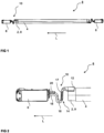
- a pre-assembled electrical cable 8 according to FIG 1 and FIG 2 has, in the embodiment shown, a solid round conductor 2 which is surrounded by an insulation sheath 4.
- a plug 6 is attached to each end of the round conductor 2 as an electrical component.
- the round conductor 2 has a blank end part 9 at each of its two opposite ends, which has a round cross-section.
- the cross-section of the round conductor 2 is preferably constant over its entire length. The round conductor 2 is therefore undeformed at the end parts 9.
- the connecting element 10 is in particular a metallic one-piece element and in one embodiment a monolithic component.
- the connecting element 10 is a (flexible) multilayer construction with a plurality (>3, especially >5) of thin metal layers 17.
- the layers 17 are only illustrated in a very simplified way in FIG 2 and only in the intermediate section 14.
- the layers 17 are welded together especially (only) at the end sides. Therefore, in a preferred embodiment, in the intermediate section 14 the layers 17 are not fixed to each other, for example they are not welded together. Therefore, the individual layers 17 can slide to some extent relative to each other. Due to this the flexibility of the intermediate section 14 is high
- the connecting element 10 is therefore in particular a metal bent part, which is preferably produced by forming from a flat metal strip. This generally has two opposite flat sides which are connected to each other via two opposite narrow sides.
- one end of the flat metal strip is preferably bent around a bending axis oriented parallel to the longitudinal direction L.
- the shell-shaped section 12 extends in the circumferential direction, for example, over an angular range of less than 180° and in particular also of less than 120° or less than 90°.
- the shell-shaped section 12 extends over an angular range of 30° to 60°.
- the shell-shaped section 12 preferably has a radius of curvature which is adapted to the radius of the round conductor 2, so that the outer side of the round conductor 2, which is freed from the insulation sheath 4, lies with its cylindrical surface on an inner side of the shell-shaped section 12. This inner side forms a partially cylindrical surface.
- the radius of curvature corresponds to the radius of the round conductor 2.
- the shell-shaped section 12 extends in the longitudinal direction L over a comparatively short length, which in the embodiment example is for example shorter than a diameter of the round conductor 2.
- the curved, shell-shaped section 12 merges into the intermediate section 14, which is formed by a section of the flat metal strip, wherein said section is bent.
- the intermediate section 14, and thus the metal strip, are formed as a whole in a curved shape and therefore are undulated.
- the intermediate section 14 has at least one arc section 18 and preferably a plurality of arc sections 18. In particular, two or three arc sections are formed.
- the intermediate section 14 is flexible in the longitudinal direction and is specifically elastic. The flexible intermediate section 14 can therefore be compressed or stretched and thus serves to compensate for length.
- a respective arc section 18 is bent around a bending axis which is oriented perpendicular to the longitudinal direction L and parallel to the flat sides of the flat metal strip.
- the intermediate section 14 finally merges into the connecting section 16, which extends in particular in a straight line and in particular in the longitudinal direction L.
- the connecting section 16 is electrically and mechanically connected to a respective plug 6 via a welded connection.
- a respective plug 6 preferably has a connection piece 20, which in turn is designed in particular as a flat metal strip.
- the respective plug 6 generally has an insulating housing in which a contact terminal not shown in more detail here is arranged, for example a socket or a plug pin, this contact terminal being electrically contacted on the connection piece 20.
- the connection piece 20 emerges from the housing and is connected to the connecting element 10 at its emerging part.
- the blank, round end part 9 is inserted into the shell-shaped section 12 and joined to it by welding.
Landscapes
- Connections Effected By Soldering, Adhesion, Or Permanent Deformation (AREA)
Claims (10)
- Elektrisches Kabel (8), insbesondere für ein Kraftfahrzeug, das einen massiven elektrischen Rundleiter (2) und ein Verbindungselement (10) aufweist, das mit dem Rundleiter (2) verbunden ist und das einen Verbindungsabschnitt (16) zur elektrischen Verbindung mit einem elektrischen Bauteil (6) aufweist, wobei das Verbindungselement (10) weiter einen schalenförmigen Abschnitt (12) aufweist, wobei ein runder Endteil (9) des Rundleiters (2) an den schalenförmigen Abschnitt (12) des Verbindungselements (10) geschweißt ist, dadurch gekennzeichnet, dass ein flexibler Zwischenabschnitt (14) zum Längenausgleich zwischen dem schalenförmigen Abschnitt (12) und dem Verbindungsabschnitt (16) angeordnet ist und dass das Verbindungselement (10) einen mehrschichtigen Aufbau mit einer Vielzahl von Schichten aufweist, wobei die Schichten innerhalb des Zwischenabschnitts (14) nicht aneinander fixiert sind.
- Elektrisches Kabel (8) nach dem vorstehenden Anspruch, dadurch gekennzeichnet, dass der flexible Zwischenabschnitt (14) gewellt ist.
- Elektrisches Kabel (8) nach einem der vorstehenden Ansprüche, dadurch gekennzeichnet, dass der Verbindungsabschnitt (16) als mindestens ein flacher Metallstreifen gebildet ist.
- Elektrisches Kabel (8) nach einem der vorstehenden Ansprüche, dadurch gekennzeichnet, dass das Verbindungselement (10) mit dem Verbindungsabschnitt (16) an dem elektrischen Bauteil (6) durch Schweißen fixiert ist.
- Elektrisches Kabel (8) nach einem der vorstehenden Ansprüche, dadurch gekennzeichnet, dass der Verbindungsabschnitt (16) an einen Verbindungsteil (20) eines Steckers (6) geschweißt ist.
- Elektrisches Kabel (8) nach einem der vorstehenden Ansprüche, dadurch gekennzeichnet, dass das Verbindungselement (10) ausschließlich durch Schweißen mit dem Rundleiter (2) sowohl elektrisch kontaktiert als auch mechanisch verbunden ist.
- Elektrisches Kabel (8) nach einem der vorstehenden Ansprüche, dadurch gekennzeichnet, dass der Rundleiter (2) ein eigensteifer Rundleiter (2) mit einem Durchmesser von mindestens 10 mm, vorzugsweise mindestens 20 mm, ist.
- Elektrisches Kabel (8) nach einem der vorstehenden Ansprüche, dadurch gekennzeichnet, dass der Rundleiter (2) ein Aluminiumleiter ist.
- Elektrisches Kabel (8) nach einem der vorstehenden Ansprüche, dadurch gekennzeichnet, dass an runden Endteilen (9) an beiden Seiten des Rundleiters (2) Verbindungselemente (10) angebracht sind.
- Kraftfahrzeug mit einem elektrischen Kabel (8) nach einem der vorstehenden Ansprüche.
Priority Applications (1)
| Application Number | Priority Date | Filing Date | Title |
|---|---|---|---|
| EP23290015.9A EP4462602B1 (de) | 2023-05-12 | 2023-05-12 | Elektrisches kabel und kraftfahrzeug mit einem solchen kabel |
Applications Claiming Priority (1)
| Application Number | Priority Date | Filing Date | Title |
|---|---|---|---|
| EP23290015.9A EP4462602B1 (de) | 2023-05-12 | 2023-05-12 | Elektrisches kabel und kraftfahrzeug mit einem solchen kabel |
Publications (2)
| Publication Number | Publication Date |
|---|---|
| EP4462602A1 EP4462602A1 (de) | 2024-11-13 |
| EP4462602B1 true EP4462602B1 (de) | 2025-02-26 |
Family
ID=86692767
Family Applications (1)
| Application Number | Title | Priority Date | Filing Date |
|---|---|---|---|
| EP23290015.9A Active EP4462602B1 (de) | 2023-05-12 | 2023-05-12 | Elektrisches kabel und kraftfahrzeug mit einem solchen kabel |
Country Status (1)
| Country | Link |
|---|---|
| EP (1) | EP4462602B1 (de) |
Family Cites Families (5)
| Publication number | Priority date | Publication date | Assignee | Title |
|---|---|---|---|---|
| JPS5434083A (en) * | 1978-04-06 | 1979-03-13 | Furukawa Electric Co Ltd:The | Joint for flexible conductor of twisted aluminium wires |
| DE102010005841B4 (de) | 2010-01-26 | 2011-12-08 | Auto-Kabel Managementgesellschaft Mbh | Kabelschuh mit schalenförmiger Ausformung und Befestigungseinrichtung |
| JP2013242991A (ja) * | 2012-05-18 | 2013-12-05 | Auto Network Gijutsu Kenkyusho:Kk | 電線の接合構造 |
| CN113708172A (zh) * | 2021-08-26 | 2021-11-26 | 长春捷翼汽车零部件有限公司 | 一种电能传输转接机构、充电插座和机动车辆 |
| CN115411538A (zh) | 2022-09-16 | 2022-11-29 | 欧托凯勃汽车线束(太仓)有限公司 | 一种曲面超声波焊接端子及配套使用的焊接组件 |
-
2023
- 2023-05-12 EP EP23290015.9A patent/EP4462602B1/de active Active
Also Published As
| Publication number | Publication date |
|---|---|
| EP4462602A1 (de) | 2024-11-13 |
Similar Documents
| Publication | Publication Date | Title |
|---|---|---|
| EP2083480B1 (de) | Anschlussklemme mit elektrischem Draht und Steckverbinder dafür | |
| CN102082366B (zh) | 车辆用连接结构 | |
| US9346420B2 (en) | Wire harness | |
| US7947904B2 (en) | Conductor and wire harness | |
| CN102082346B (zh) | 连接器 | |
| US20090249616A1 (en) | Method for connecting two electrically conductive components to one another | |
| US10965113B2 (en) | Wire harness | |
| WO2011102005A1 (ja) | 車両用の電線 | |
| US5800219A (en) | Stamped battery terminal | |
| EP3971038A1 (de) | Wasserdichter aufbau eines dreiphasenleitungsteils und dreiphasige leitungsverbindungsvorrichtung | |
| CN102195217A (zh) | 连接器 | |
| EP4462602B1 (de) | Elektrisches kabel und kraftfahrzeug mit einem solchen kabel | |
| GB2276778A (en) | Electrical connector | |
| WO2018173784A1 (ja) | 導電線 | |
| JP7810034B2 (ja) | 平型電線及び端子付き平型電線 | |
| KR200357907Y1 (ko) | 자동차용 멀티 어스 터미널 | |
| US20190305442A1 (en) | Electric wire with terminal | |
| US10826201B2 (en) | Conductive member | |
| JP6158539B2 (ja) | 電線の分岐構造 | |
| EP0694991A1 (de) | Elektrischer Kontakt aus zwei Werkstoffen | |
| JP2021034167A (ja) | ワイヤハーネス | |
| US6257909B1 (en) | Rotary joint with flat conductor and circular conductor | |
| JP7431091B2 (ja) | 接続端子 | |
| CN219436288U (zh) | 一种用于电动汽车电传导硬母排的屏蔽连接系统 | |
| JP2006338975A (ja) | 異径導体の接続金具 |
Legal Events
| Date | Code | Title | Description |
|---|---|---|---|
| PUAI | Public reference made under article 153(3) epc to a published international application that has entered the european phase |
Free format text: ORIGINAL CODE: 0009012 |
|
| STAA | Information on the status of an ep patent application or granted ep patent |
Free format text: STATUS: REQUEST FOR EXAMINATION WAS MADE |
|
| 17P | Request for examination filed |
Effective date: 20240925 |
|
| AK | Designated contracting states |
Kind code of ref document: A1 Designated state(s): AL AT BE BG CH CY CZ DE DK EE ES FI FR GB GR HR HU IE IS IT LI LT LU LV MC ME MK MT NL NO PL PT RO RS SE SI SK SM TR |
|
| GRAP | Despatch of communication of intention to grant a patent |
Free format text: ORIGINAL CODE: EPIDOSNIGR1 |
|
| STAA | Information on the status of an ep patent application or granted ep patent |
Free format text: STATUS: GRANT OF PATENT IS INTENDED |
|
| GRAJ | Information related to disapproval of communication of intention to grant by the applicant or resumption of examination proceedings by the epo deleted |
Free format text: ORIGINAL CODE: EPIDOSDIGR1 |
|
| STAA | Information on the status of an ep patent application or granted ep patent |
Free format text: STATUS: REQUEST FOR EXAMINATION WAS MADE |
|
| GRAP | Despatch of communication of intention to grant a patent |
Free format text: ORIGINAL CODE: EPIDOSNIGR1 |
|
| RIC1 | Information provided on ipc code assigned before grant |
Ipc: H01R 11/11 20060101ALN20241114BHEP Ipc: H01R 11/09 20060101ALN20241114BHEP Ipc: H01R 31/06 20060101ALI20241114BHEP Ipc: H01R 4/60 20060101ALI20241114BHEP Ipc: H01R 4/02 20060101AFI20241114BHEP |
|
| STAA | Information on the status of an ep patent application or granted ep patent |
Free format text: STATUS: GRANT OF PATENT IS INTENDED |
|
| RIC1 | Information provided on ipc code assigned before grant |
Ipc: H01R 11/11 20060101ALN20241115BHEP Ipc: H01R 11/09 20060101ALN20241115BHEP Ipc: H01R 31/06 20060101ALI20241115BHEP Ipc: H01R 4/60 20060101ALI20241115BHEP Ipc: H01R 4/02 20060101AFI20241115BHEP |
|
| INTG | Intention to grant announced |
Effective date: 20241128 |
|
| INTC | Intention to grant announced (deleted) | ||
| RIC1 | Information provided on ipc code assigned before grant |
Ipc: H01R 11/11 20060101ALN20241205BHEP Ipc: H01R 11/09 20060101ALN20241205BHEP Ipc: H01R 31/06 20060101ALI20241205BHEP Ipc: H01R 4/60 20060101ALI20241205BHEP Ipc: H01R 4/02 20060101AFI20241205BHEP |
|
| RIC1 | Information provided on ipc code assigned before grant |
Ipc: H01R 11/11 20060101ALN20241209BHEP Ipc: H01R 11/09 20060101ALN20241209BHEP Ipc: H01R 31/06 20060101ALI20241209BHEP Ipc: H01R 4/60 20060101ALI20241209BHEP Ipc: H01R 4/02 20060101AFI20241209BHEP |
|
| GRAS | Grant fee paid |
Free format text: ORIGINAL CODE: EPIDOSNIGR3 |
|
| INTG | Intention to grant announced |
Effective date: 20241219 |
|
| GRAA | (expected) grant |
Free format text: ORIGINAL CODE: 0009210 |
|
| STAA | Information on the status of an ep patent application or granted ep patent |
Free format text: STATUS: THE PATENT HAS BEEN GRANTED |
|
| AK | Designated contracting states |
Kind code of ref document: B1 Designated state(s): AL AT BE BG CH CY CZ DE DK EE ES FI FR GB GR HR HU IE IS IT LI LT LU LV MC ME MK MT NL NO PL PT RO RS SE SI SK SM TR |
|
| REG | Reference to a national code |
Ref country code: GB Ref legal event code: FG4D |
|
| REG | Reference to a national code |
Ref country code: CH Ref legal event code: EP |
|
| P01 | Opt-out of the competence of the unified patent court (upc) registered |
Free format text: CASE NUMBER: APP_4954/2025 Effective date: 20250129 |
|
| REG | Reference to a national code |
Ref country code: DE Ref legal event code: R096 Ref document number: 602023002221 Country of ref document: DE |
|
| REG | Reference to a national code |
Ref country code: IE Ref legal event code: FG4D |
|
| REG | Reference to a national code |
Ref country code: DE Ref legal event code: R082 Ref document number: 602023002221 Country of ref document: DE Ref country code: DE Ref legal event code: R081 Ref document number: 602023002221 Country of ref document: DE Owner name: LEONI WIRING SYSTEMS FRANCE, FR Free format text: FORMER OWNER: LEONI WIRING SYSTEMS FRANCE, MOTIGNY-LE-BRETONNEUX, FR |
|
| REG | Reference to a national code |
Ref country code: NL Ref legal event code: MP Effective date: 20250226 |
|
| PG25 | Lapsed in a contracting state [announced via postgrant information from national office to epo] |
Ref country code: RS Free format text: LAPSE BECAUSE OF FAILURE TO SUBMIT A TRANSLATION OF THE DESCRIPTION OR TO PAY THE FEE WITHIN THE PRESCRIBED TIME-LIMIT Effective date: 20250526 |
|
| PG25 | Lapsed in a contracting state [announced via postgrant information from national office to epo] |
Ref country code: FI Free format text: LAPSE BECAUSE OF FAILURE TO SUBMIT A TRANSLATION OF THE DESCRIPTION OR TO PAY THE FEE WITHIN THE PRESCRIBED TIME-LIMIT Effective date: 20250226 |
|
| PG25 | Lapsed in a contracting state [announced via postgrant information from national office to epo] |
Ref country code: PL Free format text: LAPSE BECAUSE OF FAILURE TO SUBMIT A TRANSLATION OF THE DESCRIPTION OR TO PAY THE FEE WITHIN THE PRESCRIBED TIME-LIMIT Effective date: 20250226 |
|
| PGFP | Annual fee paid to national office [announced via postgrant information from national office to epo] |
Ref country code: DE Payment date: 20250519 Year of fee payment: 3 |
|
| PG25 | Lapsed in a contracting state [announced via postgrant information from national office to epo] |
Ref country code: ES Free format text: LAPSE BECAUSE OF FAILURE TO SUBMIT A TRANSLATION OF THE DESCRIPTION OR TO PAY THE FEE WITHIN THE PRESCRIBED TIME-LIMIT Effective date: 20250226 |
|
| REG | Reference to a national code |
Ref country code: LT Ref legal event code: MG9D |
|
| PG25 | Lapsed in a contracting state [announced via postgrant information from national office to epo] |
Ref country code: NO Free format text: LAPSE BECAUSE OF FAILURE TO SUBMIT A TRANSLATION OF THE DESCRIPTION OR TO PAY THE FEE WITHIN THE PRESCRIBED TIME-LIMIT Effective date: 20250526 Ref country code: IS Free format text: LAPSE BECAUSE OF FAILURE TO SUBMIT A TRANSLATION OF THE DESCRIPTION OR TO PAY THE FEE WITHIN THE PRESCRIBED TIME-LIMIT Effective date: 20250626 |
|
| PG25 | Lapsed in a contracting state [announced via postgrant information from national office to epo] |
Ref country code: NL Free format text: LAPSE BECAUSE OF FAILURE TO SUBMIT A TRANSLATION OF THE DESCRIPTION OR TO PAY THE FEE WITHIN THE PRESCRIBED TIME-LIMIT Effective date: 20250226 |
|
| PG25 | Lapsed in a contracting state [announced via postgrant information from national office to epo] |
Ref country code: HR Free format text: LAPSE BECAUSE OF FAILURE TO SUBMIT A TRANSLATION OF THE DESCRIPTION OR TO PAY THE FEE WITHIN THE PRESCRIBED TIME-LIMIT Effective date: 20250226 |
|
| PG25 | Lapsed in a contracting state [announced via postgrant information from national office to epo] |
Ref country code: PT Free format text: LAPSE BECAUSE OF FAILURE TO SUBMIT A TRANSLATION OF THE DESCRIPTION OR TO PAY THE FEE WITHIN THE PRESCRIBED TIME-LIMIT Effective date: 20250626 Ref country code: LV Free format text: LAPSE BECAUSE OF FAILURE TO SUBMIT A TRANSLATION OF THE DESCRIPTION OR TO PAY THE FEE WITHIN THE PRESCRIBED TIME-LIMIT Effective date: 20250226 |
|
| PGFP | Annual fee paid to national office [announced via postgrant information from national office to epo] |
Ref country code: FR Payment date: 20250523 Year of fee payment: 3 |
|
| PG25 | Lapsed in a contracting state [announced via postgrant information from national office to epo] |
Ref country code: BG Free format text: LAPSE BECAUSE OF FAILURE TO SUBMIT A TRANSLATION OF THE DESCRIPTION OR TO PAY THE FEE WITHIN THE PRESCRIBED TIME-LIMIT Effective date: 20250226 Ref country code: GR Free format text: LAPSE BECAUSE OF FAILURE TO SUBMIT A TRANSLATION OF THE DESCRIPTION OR TO PAY THE FEE WITHIN THE PRESCRIBED TIME-LIMIT Effective date: 20250527 |
|
| PG25 | Lapsed in a contracting state [announced via postgrant information from national office to epo] |
Ref country code: SE Free format text: LAPSE BECAUSE OF FAILURE TO SUBMIT A TRANSLATION OF THE DESCRIPTION OR TO PAY THE FEE WITHIN THE PRESCRIBED TIME-LIMIT Effective date: 20250226 |
|
| PG25 | Lapsed in a contracting state [announced via postgrant information from national office to epo] |
Ref country code: SM Free format text: LAPSE BECAUSE OF FAILURE TO SUBMIT A TRANSLATION OF THE DESCRIPTION OR TO PAY THE FEE WITHIN THE PRESCRIBED TIME-LIMIT Effective date: 20250226 |
|
| PG25 | Lapsed in a contracting state [announced via postgrant information from national office to epo] |
Ref country code: DK Free format text: LAPSE BECAUSE OF FAILURE TO SUBMIT A TRANSLATION OF THE DESCRIPTION OR TO PAY THE FEE WITHIN THE PRESCRIBED TIME-LIMIT Effective date: 20250226 |
|
| PG25 | Lapsed in a contracting state [announced via postgrant information from national office to epo] |
Ref country code: IT Free format text: LAPSE BECAUSE OF FAILURE TO SUBMIT A TRANSLATION OF THE DESCRIPTION OR TO PAY THE FEE WITHIN THE PRESCRIBED TIME-LIMIT Effective date: 20250226 |
|
| PG25 | Lapsed in a contracting state [announced via postgrant information from national office to epo] |
Ref country code: AT Free format text: LAPSE BECAUSE OF FAILURE TO SUBMIT A TRANSLATION OF THE DESCRIPTION OR TO PAY THE FEE WITHIN THE PRESCRIBED TIME-LIMIT Effective date: 20250226 |
|
| PG25 | Lapsed in a contracting state [announced via postgrant information from national office to epo] |
Ref country code: CZ Free format text: LAPSE BECAUSE OF FAILURE TO SUBMIT A TRANSLATION OF THE DESCRIPTION OR TO PAY THE FEE WITHIN THE PRESCRIBED TIME-LIMIT Effective date: 20250226 Ref country code: EE Free format text: LAPSE BECAUSE OF FAILURE TO SUBMIT A TRANSLATION OF THE DESCRIPTION OR TO PAY THE FEE WITHIN THE PRESCRIBED TIME-LIMIT Effective date: 20250226 |
|
| PG25 | Lapsed in a contracting state [announced via postgrant information from national office to epo] |
Ref country code: SK Free format text: LAPSE BECAUSE OF FAILURE TO SUBMIT A TRANSLATION OF THE DESCRIPTION OR TO PAY THE FEE WITHIN THE PRESCRIBED TIME-LIMIT Effective date: 20250226 |
|
| REG | Reference to a national code |
Ref country code: DE Ref legal event code: R097 Ref document number: 602023002221 Country of ref document: DE |
|
| PLBE | No opposition filed within time limit |
Free format text: ORIGINAL CODE: 0009261 |
|
| STAA | Information on the status of an ep patent application or granted ep patent |
Free format text: STATUS: NO OPPOSITION FILED WITHIN TIME LIMIT |
|
| PG25 | Lapsed in a contracting state [announced via postgrant information from national office to epo] |
Ref country code: LU Free format text: LAPSE BECAUSE OF NON-PAYMENT OF DUE FEES Effective date: 20250512 |
|
| PG25 | Lapsed in a contracting state [announced via postgrant information from national office to epo] |
Ref country code: MC Free format text: LAPSE BECAUSE OF FAILURE TO SUBMIT A TRANSLATION OF THE DESCRIPTION OR TO PAY THE FEE WITHIN THE PRESCRIBED TIME-LIMIT Effective date: 20250226 |
|
| 26N | No opposition filed |
Effective date: 20251127 |