EP4462004A2 - Dispositif d'aspiration pour évacuer un mélange de fluides, notamment de matières fécales, d'un récipient collecteur - Google Patents
Dispositif d'aspiration pour évacuer un mélange de fluides, notamment de matières fécales, d'un récipient collecteur Download PDFInfo
- Publication number
- EP4462004A2 EP4462004A2 EP24194746.4A EP24194746A EP4462004A2 EP 4462004 A2 EP4462004 A2 EP 4462004A2 EP 24194746 A EP24194746 A EP 24194746A EP 4462004 A2 EP4462004 A2 EP 4462004A2
- Authority
- EP
- European Patent Office
- Prior art keywords
- shut
- suction device
- pawl
- housing
- handling means
- Prior art date
- Legal status (The legal status is an assumption and is not a legal conclusion. Google has not performed a legal analysis and makes no representation as to the accuracy of the status listed.)
- Pending
Links
Images


Classifications
-
- B—PERFORMING OPERATIONS; TRANSPORTING
- B67—OPENING, CLOSING OR CLEANING BOTTLES, JARS OR SIMILAR CONTAINERS; LIQUID HANDLING
- B67D—DISPENSING, DELIVERING OR TRANSFERRING LIQUIDS, NOT OTHERWISE PROVIDED FOR
- B67D7/00—Apparatus or devices for transferring liquids from bulk storage containers or reservoirs into vehicles or into portable containers, e.g. for retail sale purposes
- B67D7/02—Apparatus or devices for transferring liquids from bulk storage containers or reservoirs into vehicles or into portable containers, e.g. for retail sale purposes for transferring liquids other than fuel or lubricants
-
- E—FIXED CONSTRUCTIONS
- E03—WATER SUPPLY; SEWERAGE
- E03F—SEWERS; CESSPOOLS
- E03F1/00—Methods, systems, or installations for draining-off sewage or storm water
- E03F1/008—Temporary fluid connections for emptying mobile sewage holding tanks, e.g. of trailers, boats
-
- B—PERFORMING OPERATIONS; TRANSPORTING
- B61—RAILWAYS
- B61D—BODY DETAILS OR KINDS OF RAILWAY VEHICLES
- B61D35/00—Sanitation
- B61D35/005—Toilet facilities
- B61D35/007—Toilet facilities comprising toilet waste receiving, treatment, storage, disposal or removal devices
-
- B—PERFORMING OPERATIONS; TRANSPORTING
- B67—OPENING, CLOSING OR CLEANING BOTTLES, JARS OR SIMILAR CONTAINERS; LIQUID HANDLING
- B67D—DISPENSING, DELIVERING OR TRANSFERRING LIQUIDS, NOT OTHERWISE PROVIDED FOR
- B67D7/00—Apparatus or devices for transferring liquids from bulk storage containers or reservoirs into vehicles or into portable containers, e.g. for retail sale purposes
- B67D7/06—Details or accessories
-
- F—MECHANICAL ENGINEERING; LIGHTING; HEATING; WEAPONS; BLASTING
- F16—ENGINEERING ELEMENTS AND UNITS; GENERAL MEASURES FOR PRODUCING AND MAINTAINING EFFECTIVE FUNCTIONING OF MACHINES OR INSTALLATIONS; THERMAL INSULATION IN GENERAL
- F16K—VALVES; TAPS; COCKS; ACTUATING-FLOATS; DEVICES FOR VENTING OR AERATING
- F16K3/00—Gate valves or sliding valves, i.e. cut-off apparatus with closing members having a sliding movement along the seat for opening and closing
- F16K3/02—Gate valves or sliding valves, i.e. cut-off apparatus with closing members having a sliding movement along the seat for opening and closing with flat sealing faces; Packings therefor
- F16K3/04—Gate valves or sliding valves, i.e. cut-off apparatus with closing members having a sliding movement along the seat for opening and closing with flat sealing faces; Packings therefor with pivoted closure members
-
- F—MECHANICAL ENGINEERING; LIGHTING; HEATING; WEAPONS; BLASTING
- F16—ENGINEERING ELEMENTS AND UNITS; GENERAL MEASURES FOR PRODUCING AND MAINTAINING EFFECTIVE FUNCTIONING OF MACHINES OR INSTALLATIONS; THERMAL INSULATION IN GENERAL
- F16K—VALVES; TAPS; COCKS; ACTUATING-FLOATS; DEVICES FOR VENTING OR AERATING
- F16K31/00—Actuating devices; Operating means; Releasing devices
- F16K31/44—Mechanical actuating means
- F16K31/53—Mechanical actuating means with toothed gearing
- F16K31/535—Mechanical actuating means with toothed gearing for rotating valves
-
- F—MECHANICAL ENGINEERING; LIGHTING; HEATING; WEAPONS; BLASTING
- F16—ENGINEERING ELEMENTS AND UNITS; GENERAL MEASURES FOR PRODUCING AND MAINTAINING EFFECTIVE FUNCTIONING OF MACHINES OR INSTALLATIONS; THERMAL INSULATION IN GENERAL
- F16K—VALVES; TAPS; COCKS; ACTUATING-FLOATS; DEVICES FOR VENTING OR AERATING
- F16K31/00—Actuating devices; Operating means; Releasing devices
- F16K31/44—Mechanical actuating means
- F16K31/60—Handles
- F16K31/602—Pivoting levers, e.g. single-sided
-
- F—MECHANICAL ENGINEERING; LIGHTING; HEATING; WEAPONS; BLASTING
- F16—ENGINEERING ELEMENTS AND UNITS; GENERAL MEASURES FOR PRODUCING AND MAINTAINING EFFECTIVE FUNCTIONING OF MACHINES OR INSTALLATIONS; THERMAL INSULATION IN GENERAL
- F16L—PIPES; JOINTS OR FITTINGS FOR PIPES; SUPPORTS FOR PIPES, CABLES OR PROTECTIVE TUBING; MEANS FOR THERMAL INSULATION IN GENERAL
- F16L37/00—Couplings of the quick-acting type
- F16L37/28—Couplings of the quick-acting type with fluid cut-off means
- F16L37/38—Couplings of the quick-acting type with fluid cut-off means with fluid cut-off means in only one of two pipe-end fittings
- F16L37/47—Couplings of the quick-acting type with fluid cut-off means with fluid cut-off means in only one of two pipe-end fittings with a tap or cock
Definitions
- the invention relates to a suction device for removing a mixed fluid, in particular containing feces, from a collecting container, in particular from a waste tank of a rail vehicle, with a housing with a mixed fluid inlet and a mixed fluid outlet, a flow channel which extends in the housing between the inlet and the outlet, a locking pawl mounted on the housing, which is designed to interact with a corresponding recess on the collecting container and can be pivoted back and forth between a locked position and an unlocked position, a shut-off element which can be moved back and forth between a release position and a locking position, and a handling means mounted on the housing for actuating the shut-off element.
- Vehicles particularly rail vehicles or other goods and passenger vehicles such as caravans, often have collection containers for collecting faeces. These collection containers must be emptied at regular intervals.
- collection containers often have an outlet, such as a nozzle on the outside of a vehicle to which a hose coupling of a suction hose can be connected so that the faeces in the tank can be sucked out using negative pressure.
- shut-off device only allow the shut-off device to be released after the coupling has taken place. This means that a further, separate handling step is required. From a practical point of view, however, coupling the locking mechanism to the shut-off device is desirable.
- the object of the present invention is therefore to provide a suction device which is improved with respect to at least one of the disadvantages mentioned.
- the object of the invention is to provide a suction device with simplified operation while maintaining the same level of safety against the escape of mixed fluid from the collecting container.
- the present invention solves the problem in a suction device of the type mentioned at the beginning in that the handling means is operatively connected to the locking pawl in such a way that when the locking pawl is moved into the unlocked position, the shut-off element is brought into the closed position.
- the shut-off element can thus be brought by the handling means from a release position, in which the mixed fluid inlet and the mixed fluid outlet are in fluid communication through the flow channel, into a blocking position in which the flow channel is closed by the shut-off element.
- a suction device is thus specified in which the shut-off element is brought into the blocking position as soon as the locking pawl is moved into the unlocked position. This effectively ensures that the flow channel is shut off without the need for an additional operating step and effectively prevents the undesired escape of mixed fluid from the collecting container.
- the handling means is operatively connected to the pawl in such a way that when the shut-off device is moved into the release position, the pawl is brought into the locked position.
- the operation of the suction device is thus simplified by the simultaneous actuation of the shut-off device and the pawl to lock the suction device and the initiation of the suction process is accelerated.
- the suction device further comprises a coupling body that can be moved along a longitudinal axis, in particular a wedge, which is operatively connected to the handling means and is designed to move the pawl back and forth between the locked position and the unlocked position.
- a coupling body which is preferably designed as a wedge, provides a simple and functional component for coupling the pawl to the handling means. These are mechanically coupled in such a way that the shut-off element is brought into the locked position by the handling means as soon as the pawl is moved into the unlocked position.
- the coupling body is also designed to bring the pawl into the locked position as soon as the shut-off element is brought into the release position by actuation by means of the handling means.
- the recess of the collecting container is formed in the area of a connection that can be coupled to the mixing fluid inlet, and the locking pawl is pivotally mounted in the area of the mixing fluid inlet and is designed to be brought into engagement with the connection of the collecting container.
- the suction device is thus locked at the first contact between the collecting container and the suction device, which usually takes place between the connection of the collecting container and the mixing fluid inlet of the suction device.
- grooves running in the circumferential direction can be provided on the outside of the formed connection, into which the locking pawl engages by means of a pivoting movement. The process time is thus reduced, since the initial contact between the collecting container and the suction device already enables locking by the locking pawl.
- the shut-off device is arranged in the housing so that it can rotate, and the release position and the blocking position of the shut-off device correspond to different rotational positions of the shut-off device.
- the axis of rotation of the shut-off device is preferably parallel, particularly preferably coaxial, to a longitudinal axis of the flow channel in which the shut-off device is arranged.
- the handling means is preferably operatively connected to the shut-off device by means of a gear transmission, wherein the gear transmission is designed to convert the actuating movement of the handling means into the rotary movement of the shut-off device.
- the shut-off device comprises a constriction body which is movably mounted in the housing and is designed to reduce a cross-section of the flow channel in sections or along its entire longitudinal axis, and wherein the handling means is designed to actuate the shut-off device by moving the constriction body.
- a constriction body which reduces the cross-section of the flow channel, the blocking of the flow channel is ensured in a structurally simple manner in order to separate the mixed fluid inlet of the suction device from the connection of the collecting container.
- This also allows simple and robust mechanical actuation by the handling means, which can be carried out manually or by motor.
- the device according to the invention is low in wear and maintenance and also cost-effective. The suction process can initially be started with a large flow channel cross-section so that a high volume flow is achieved.
- the handling means has a slide, and the coupling body is arranged on the slide.
- the handling means is moved back and forth along the housing to lock or unlock the shut-off device.
- the coupling body By arranging the coupling body on the slide, corresponding to the pawl, the latter also carries out a movement along the longitudinal axis and can thus be brought into engagement with the pawl.
- the pawl is then inserted between the locked position and the unlocked position depending on the position of the slider.
- the combination of a linearly movable slide with a rotary arrangement of the shut-off device has proven to be particularly advantageous.
- the linear movement of the slide is converted into a rotary movement of the shut-off device.
- the linear movement of the handling device is user-intuitive for coupling and uncoupling the suction device, and at the same time the rotary movement of the shut-off device or the constriction body enables a compact design.
- the handling means has a toggle lever, and the coupling body is coupled to the toggle lever by means of a pivotally mounted lever.
- the coupling body functions as a slider.
- a toggle lever can be operated in a simple, intuitive manner and offers a high degree of safety.
- a groove is formed on the housing, which is designed to guide the coupling body. This prevents the coupling body from malfunctioning due to twisting or tipping, for example due to dynamic loading of the suction device as a result of pumping.
- the shut-off device can be moved into a slurping position in addition to the blocking position and the release position, so that the shut-off device is designed to close the flow channel in a fluid-tight manner in the blocking position, to open it in the release position, and to open it only in a narrowed manner in the slurping position, in particular such that the cross-section of the flow channel is smaller in the slurping position than in the release position.
- the multifunctionality of the shut-off device thus eliminates the need for an additional shut-off valve, which significantly simplifies the construction of the suction device.
- the weight of the suction device according to the invention is also reduced in this way.
- a closure element which is designed to close the flow channel could be activated by moving the shut-off device into the blocking position. It is also possible possible possible to vary the diameter of the flow channel, preferably during a suction process.
- the shut-off device By moving the shut-off device into the slurping position, in which the cross-section of the flow channel is smaller than in the release position, the fluid in the flow channel is accelerated compared to the speed in the outlet of the collecting container, so that a turbulent flow is created.
- the turbulent flow ensures that solid or highly viscous components of the mixed fluid are also entrained and sucked away.
- the effect is not only limited to the flow channel, but also at least partially to the outlet of the collecting container, in particular a connected nozzle, so that this too is freed of the mixed fluid or feces.
- the shut-off device in which the shut-off device is arranged in the housing so as to be rotatable, wherein the release position and the blocking position of the shut-off device correspond to different rotational positions of the shut-off device, the slurping position corresponds to a further rotational position of the shut-off device.
- the slurping position is arranged between the release position and the blocking position. This means that every time the suction device is to be uncoupled, the shut-off device must necessarily pass through the slurping position when the handling means for unlocking the locking pawls is operated. This in turn ensures that the suction device is always free of faeces at its inlet end when the suction device is uncoupled.
- a suction device 1 for removing a mixed fluid, in particular containing faeces, from a collecting container has a housing 3 with a mixed fluid inlet 5 and a mixed fluid outlet 7.
- the housing 3 has a longitudinal axis 4, a cylindrical housing section 3a, and a housing section 3b with a polygonal cross-section.
- the housing section 3b thus has a plurality of wall segments arranged at an angle to one another and running essentially flat, which extend along the longitudinal axis 4.
- the mixed fluid inlet 5 can be coupled in a fluid-conducting manner to a connection of a collecting container (not shown) and the mixed fluid outlet 7 can be connected in a fluid-conducting manner to a suction line (not shown).
- a flow channel 9 is arranged between the mixed fluid inlet 5 and the mixed fluid outlet 7.
- a locking pawl 11 is also arranged on the housing 3.
- the locking pawl 11 is designed to pass through a through hole 15 which is provided on the cylindrical Housing part 3a, in particular in the area of the mixed fluid inlet 5, is designed to at least partially reach through.
- the locking pawl 11 can be moved through the through opening 15 in such a way that it can engage with an outlet of a collecting container and particularly preferably with a correspondingly designed recess in the collecting container.
- Several locking pawls 11 can be provided, for example 2, 3, 4, or more locking pawls.
- the suction device 1 further comprises a handling means 13 which is pivotably arranged on the housing and which is in the present case designed as a toggle lever 17.
- the toggle lever 17 is pivotably arranged on the housing 3 by means of a toggle lever shaft 22.
- the toggle lever shaft 22 is connected to the toggle lever 17 in a rotationally fixed manner, so that pivoting the toggle lever 17 causes the toggle lever shaft 22 to rotate.
- a lever 25 is arranged on the toggle lever 17 on each side of the housing 3 so that it can rotate.
- the lever 25 is connected to a coupling body 19 so that it can rotate.
- the coupling body 19 has a wedge section 20.
- the coupling body 19 with the wedge section 20 is also guided in a guide 27 which extends essentially parallel to the longitudinal axis 4. Pivoting the toggle lever 17 therefore results in the pivoting movement being transformed into a linear movement of the coupling body 19 by means of the lever 25. In other words, the axial position of the coupling body 19 can be adjusted by the pivoting position of the toggle lever 17.
- the wedge portion 20 of the coupling body 19 is designed to come into contact with the pawl 11 in such a way that a movement of the coupling body 19 with the wedge portion 20 in the direction of the mixing fluid inlet 5 causes the wedge portion 20 to slide under the pawl 11.
- the pawl 11 is mounted so that it can rotate about a pawl pivot axis 29. If the wedge section 20 of the coupling body 19 comes into contact with the pawl 11, the latter is lifted off in the contact area between the pawl 11 and the wedge section 20 of the coupling body 19 by sliding on the wedge section 20. Due to the mounting of the pawl 11 about the pawl pivot axis 29, this causes a locking section 31 of the pawl 11 to move inwards through the through opening 15.
- the locking portion 31 of the pawl 11 can be brought into engagement with an outlet of a collecting container (not shown) and the suction device 1 can thus be reversibly coupled thereto.
- the suction device 1 is in a starting position in which the flow channel 9 is closed by means of the shut-off device 21. Therefore, no fluid residues can escape from the mixed fluid inlet 5.
- the toggle lever 17 is in a pivoting position facing away from the housing 3. This position of the toggle lever 17 causes the coupling body 19 to remain movable and in any case not to be forced inwards through the through opening 15.
- the suction device 1 can be applied in the operating position shown, for example, to a connection of a collecting container (not shown).
- the position of the toggle lever 17, as shown in the Figures 2a - c shown, causes the coupling of the toggle lever shaft with the shut-off device 21 to rotate into a blocking position. Fluid flow through the flow channel 9 is thus prevented.
- the suction device 1 In the operating state shown, the suction device 1 is in a post-suction position, also referred to as a slurping position.
- the flow channel 9 In the post-suction position, the flow channel 9 is narrowed by the shut-off device 21, but not completely shut off.
- the narrowing of the flow channel 9 causes an acceleration of the fluid flow through the flow channel 9 and turbulence is induced within the flow.
- Residual quantities of the mixed fluid in particular in the area of the mixed fluid inlet 5, are whirled up by the turbulent flow, which means in particular that it is ensured that fluid residues no longer adhere to the mixed fluid inlet, and residual quantities of fluid can then be removed from the suction device 1.
- the position of the knee lever 17 of the Figures 3a-c The operating position shown also requires that the coupling body 19 comes into contact with the pawl 11, and in particular the wedge section 20 of the coupling body 19 lifts the pawl 11 in the contact area, whereby the locking section 31 of the pawl 11 moves through the through opening 12. If the suction device 1 is coupled to an outlet of a collecting container while the suction device 1 is in the post-suction position, the suction device 1 remains coupled to the outlet while passing through the post-suction position. Only after the toggle lever 17 has been moved into the position shown in the Figures 2a - c shown position, the suction device 1 can be removed from the collection container.
- the suction device 1 is in a suction position.
- the position of the toggle lever 17 causes the coupling body 19 with the wedge section 20 to lift the pawl 11 in the contact area, whereby the locking section 31 of the pawl 11 is pivoted through the through opening 15.
- the suction device 1 can be connected firmly and fluid-tight to an outlet of a collecting container.
- the position of the toggle lever 17 also causes the shut-off element 21 to be moved into an open position in a known manner, so that a fluid flow through the flow channel 9 is released.
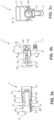
- FIGS. 5a and 5b show a first side view of another preferred embodiment of the suction device 1' according to the invention in a locked and an unlocked position.
- the suction device 1' has a housing 3' with a mixed fluid inlet 5' and a mixed fluid outlet 7'.
- a closable flow channel 9' extends between the inlet and outlet.
- the suction device 1' further comprises a locking pawl 11' which is mounted on the housing 3' and is designed to cooperate with a corresponding recess on the collecting container and can be pivoted back and forth between a locked position and an unlocked position.
- a handling means 13' is mounted on the housing 3'.
- the handling means 13' and the locking pawl 11' are operatively connected in such a way that when the locking pawl 11' is moved into the unlocked position, the shut-off device 21' is brought into the locking position.
- the handling means 13' and the pawl 11' in such a way that when the shut-off device 21' moves into the release position, the pawl 11' is brought into the locked position.
- the handling means 13' is designed here as a toggle lever, which is operatively connected to a coupling body 19', a wedge according to this embodiment, which can be moved along a longitudinal axis.
- the coupling body 19' is designed to move the pawl 11' back and forth between the locked position and the unlocked position.
- the handling means 13' is designed to actuate a shut-off device 21' with a constriction body 23'.
- the constriction body 23' is movable relative to the inlet and/or outlet 7' into the blocking position and into the release position, wherein the constriction body 23' is designed to close the flow channel 9' in a fluid-tight manner in the blocking position and to release it in the release position.
- the handling means 13' and the coupling body 19' are operatively connected by means of a lever 25'.
- the handling means 13' pivots to actuate the shut-off device 21', the pivoting movement is translated into a linear movement by the lever 25'.
- the coupling body 19' consequently moves linearly along the longitudinal axis 4.
- a recess 15' is formed in the housing 3', through which an inlet-side part of the locking pawl 11' can be moved into the locking position by means of a pivoting movement.
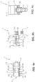
- FIGS. 6a and 6b show a second side view of another preferred embodiment of the suction device 1' according to the invention in a locked and an unlocked position.
- the coupling body 19' is guided in its movement by means of a groove 27 ⁇ which is formed in the housing 3'.
- the shut-off device 21' which can be actuated by the toggle lever 13', is designed to completely close the flow channel 9' in the shut-off position. In the release position, the flow channel 9' is released by the shut-off device 21'.
- shut-off device 21' can also be moved into a third position, namely a so-called slurping position, in which the flow channel is only narrowed but not completely closed.
Landscapes
- Engineering & Computer Science (AREA)
- General Engineering & Computer Science (AREA)
- Mechanical Engineering (AREA)
- Health & Medical Sciences (AREA)
- Public Health (AREA)
- Environmental & Geological Engineering (AREA)
- Epidemiology (AREA)
- General Health & Medical Sciences (AREA)
- Life Sciences & Earth Sciences (AREA)
- Hydrology & Water Resources (AREA)
- Water Supply & Treatment (AREA)
- External Artificial Organs (AREA)
- Lubrication Details And Ventilation Of Internal Combustion Engines (AREA)
- Quick-Acting Or Multi-Walled Pipe Joints (AREA)
- Sampling And Sample Adjustment (AREA)
- Feeding, Discharge, Calcimining, Fusing, And Gas-Generation Devices (AREA)
Applications Claiming Priority (2)
| Application Number | Priority Date | Filing Date | Title |
|---|---|---|---|
| DE202018105346.9U DE202018105346U1 (de) | 2018-09-18 | 2018-09-18 | Absaugvorrichtung zum Abführen eines Mischfluids, insbesondere Fäkalien enthaltend,aus einem Sammelbehälter |
| EP19197674.5A EP3626896B1 (fr) | 2018-09-18 | 2019-09-17 | Dispositif d'aspiration permettant d'évacuer un fluide mélangé, en particulier contenant des matières fécales, d'un réservoir collecteur |
Related Parent Applications (2)
| Application Number | Title | Priority Date | Filing Date |
|---|---|---|---|
| EP19197674.5A Division EP3626896B1 (fr) | 2018-09-18 | 2019-09-17 | Dispositif d'aspiration permettant d'évacuer un fluide mélangé, en particulier contenant des matières fécales, d'un réservoir collecteur |
| EP19197674.5A Division-Into EP3626896B1 (fr) | 2018-09-18 | 2019-09-17 | Dispositif d'aspiration permettant d'évacuer un fluide mélangé, en particulier contenant des matières fécales, d'un réservoir collecteur |
Publications (2)
| Publication Number | Publication Date |
|---|---|
| EP4462004A2 true EP4462004A2 (fr) | 2024-11-13 |
| EP4462004A3 EP4462004A3 (fr) | 2025-01-08 |
Family
ID=67997346
Family Applications (2)
| Application Number | Title | Priority Date | Filing Date |
|---|---|---|---|
| EP19197674.5A Active EP3626896B1 (fr) | 2018-09-18 | 2019-09-17 | Dispositif d'aspiration permettant d'évacuer un fluide mélangé, en particulier contenant des matières fécales, d'un réservoir collecteur |
| EP24194746.4A Pending EP4462004A3 (fr) | 2018-09-18 | 2019-09-17 | Dispositif d'aspiration pour évacuer un mélange de fluides, notamment de matières fécales, d'un récipient collecteur |
Family Applications Before (1)
| Application Number | Title | Priority Date | Filing Date |
|---|---|---|---|
| EP19197674.5A Active EP3626896B1 (fr) | 2018-09-18 | 2019-09-17 | Dispositif d'aspiration permettant d'évacuer un fluide mélangé, en particulier contenant des matières fécales, d'un réservoir collecteur |
Country Status (6)
| Country | Link |
|---|---|
| US (1) | US11447160B2 (fr) |
| EP (2) | EP3626896B1 (fr) |
| CN (1) | CN110902637B (fr) |
| DE (1) | DE202018105346U1 (fr) |
| ES (1) | ES3006480T3 (fr) |
| PL (1) | PL3626896T3 (fr) |
Families Citing this family (2)
| Publication number | Priority date | Publication date | Assignee | Title |
|---|---|---|---|---|
| US11912213B2 (en) * | 2018-05-01 | 2024-02-27 | Thetford Bv | Discharge device for vehicle wastewater management system |
| USD967928S1 (en) * | 2019-03-22 | 2022-10-25 | Thetford Bv | Discharge device for a wastewater management system of a recreational vehicle |
Citations (2)
| Publication number | Priority date | Publication date | Assignee | Title |
|---|---|---|---|---|
| US4103712A (en) | 1976-12-15 | 1978-08-01 | Nasa | Positive isolation disconnect |
| US20020171057A1 (en) | 2001-05-16 | 2002-11-21 | David Scobie | Hose coupling lock for a valve and method of use of the same |
Family Cites Families (19)
| Publication number | Priority date | Publication date | Assignee | Title |
|---|---|---|---|---|
| US2770474A (en) | 1952-12-23 | 1956-11-13 | John T Krapp | Valved separable coupling |
| US2983479A (en) * | 1958-09-11 | 1961-05-09 | Waterous Co | Discharge valve and operating mechanism |
| US4135551A (en) * | 1977-05-31 | 1979-01-23 | Fmc Corporation | Modified dry-break coupler |
| US4234161A (en) * | 1978-12-06 | 1980-11-18 | Dover Corporation | Linkage assembly for a coupler |
| US4575130A (en) * | 1982-04-15 | 1986-03-11 | Dover Corporation | Coupling apparatus |
| DE4235887A1 (de) | 1992-10-23 | 1994-04-28 | Walkenhorst Stefan | Vorrichtung zum Spannen und Kontaktieren von Profilen oder Blechen in einer Farbbeschichtungsanlage |
| US5535984A (en) * | 1994-06-07 | 1996-07-16 | Dover Corporation | Safety coupler locking means |
| US5671777A (en) * | 1995-07-17 | 1997-09-30 | Dover Corporation | Couplings for joining fluid conduits |
| US6354320B1 (en) * | 2000-03-01 | 2002-03-12 | Task Force Tips, Inc. | Acceleration sensitive shut off valve for firefighting equipment |
| DE202004019308U1 (de) * | 2004-12-14 | 2006-04-20 | Hugo Vogelsang Maschinenbau Gmbh | Vorrichtung zum Absaugen von Schmutzwasser und Fäkalien aus Bahnwaggons |
| DE102007011210B3 (de) * | 2007-03-08 | 2008-04-03 | Werner Haag | Schlauchkupplung für die Fäkalienentsorgung an Schienenfahrzeugen |
| US7823993B2 (en) | 2007-04-03 | 2010-11-02 | Carefusion 303, Inc. | Piezo actuated slide latching mechanism |
| DE202007018142U1 (de) * | 2007-12-22 | 2009-03-05 | Weh, Erwin | Kupplung, insbesondere für LNG |
| US8113240B2 (en) * | 2008-08-01 | 2012-02-14 | Marshall Excelsior Company | Low emission fluid transfer device |
| DE202011002009U1 (de) | 2011-01-27 | 2012-04-30 | Hugo Vogelsang Maschinenbau Gmbh | Absaugkupplung |
| CN102902305B (zh) | 2011-07-29 | 2015-09-30 | 兆利科技工业股份有限公司 | 杠杆循环释放枢纽器及具有该枢纽器的插接装置 |
| DE102012103061A1 (de) * | 2012-03-23 | 2013-09-26 | Andreas von Keitz | Kupplung zum Anschluss fluidführender Leitungen |
| CA2931359C (fr) * | 2013-12-23 | 2018-03-06 | Gervee Energy Services | Combinaison de dispositif d'actionneur de clapet a protection contre le deversement |
| CA3037295A1 (fr) * | 2016-10-28 | 2018-05-03 | A & A International, Llc | Systeme de propulsion hydraulique thermique |
-
2018
- 2018-09-18 DE DE202018105346.9U patent/DE202018105346U1/de active Active
-
2019
- 2019-09-17 PL PL19197674.5T patent/PL3626896T3/pl unknown
- 2019-09-17 EP EP19197674.5A patent/EP3626896B1/fr active Active
- 2019-09-17 US US16/573,467 patent/US11447160B2/en active Active
- 2019-09-17 EP EP24194746.4A patent/EP4462004A3/fr active Pending
- 2019-09-17 ES ES19197674T patent/ES3006480T3/es active Active
- 2019-09-18 CN CN201910880795.2A patent/CN110902637B/zh active Active
Patent Citations (2)
| Publication number | Priority date | Publication date | Assignee | Title |
|---|---|---|---|---|
| US4103712A (en) | 1976-12-15 | 1978-08-01 | Nasa | Positive isolation disconnect |
| US20020171057A1 (en) | 2001-05-16 | 2002-11-21 | David Scobie | Hose coupling lock for a valve and method of use of the same |
Also Published As
| Publication number | Publication date |
|---|---|
| US20200086894A1 (en) | 2020-03-19 |
| PL3626896T3 (pl) | 2025-04-07 |
| EP4462004A3 (fr) | 2025-01-08 |
| EP3626896B1 (fr) | 2024-11-27 |
| EP3626896C0 (fr) | 2024-11-27 |
| DE202018105346U1 (de) | 2019-12-19 |
| CN110902637B (zh) | 2023-06-27 |
| ES3006480T3 (en) | 2025-03-18 |
| US11447160B2 (en) | 2022-09-20 |
| EP3626896A1 (fr) | 2020-03-25 |
| CN110902637A (zh) | 2020-03-24 |
Similar Documents
| Publication | Publication Date | Title |
|---|---|---|
| EP1759131B1 (fr) | Dispositif actionneur permettant de commander un mecanisme de verrouillage | |
| EP2565469B1 (fr) | Blind rivet setting device with pressure generator | |
| EP1831495A1 (fr) | Mecanisme de commande dote d'au moins un bras de reglage | |
| EP2668082B1 (fr) | Raccord d'évacuation par aspiration | |
| EP2326778A1 (fr) | Serrure de porte de véhicule automobile | |
| EP3612697A1 (fr) | Serrure pour véhicule à moteur | |
| EP4127369B1 (fr) | Cliquet à commande forcée de serrure de capot par pêne pivotant à course double | |
| DE20004524U1 (de) | Stufenloser Türfeststeller | |
| EP3626896B1 (fr) | Dispositif d'aspiration permettant d'évacuer un fluide mélangé, en particulier contenant des matières fécales, d'un réservoir collecteur | |
| EP4263319A2 (fr) | Attelage de traction automatique | |
| EP2572940B1 (fr) | Toilette pour véhicules, notamment pour bus, camping-cars, caravanes et yachts | |
| EP4172513B1 (fr) | Système d'actionnement de verrouillage de stationnement doté d'un cylindre d'actionnement à double action sur l'élément de verrouillage, et procédé d'actionnement | |
| WO2013087454A1 (fr) | Dispositif de verrouillage pour un capot d'un véhicule, procédé d'actionnement | |
| DE102019132411A1 (de) | Zapfventil | |
| EP0568890A1 (fr) | Raccord pour une conduite à vide et à fluide | |
| EP1386812B1 (fr) | Cylindre de frein à ressort pour véhicules routiers | |
| DE102012107145A1 (de) | Kraftfahrzeugtürverschluss | |
| EP3899174B1 (fr) | Serrure conçue pour un véhicule automobile | |
| DE102011010303A1 (de) | Toilette für Fahrzeuge, insbesondere für Busse, Reisemobile, Caravans und Yachten | |
| DE102017118128A1 (de) | Verriegelungsvorrichtung zum Verriegeln einer Mechanik eines Fluggeräts | |
| DE10259627A1 (de) | Schnellanschlusskupplung mit Betätigungseinrichtung für die Übertragung eines gasfärmigen und/oder flüssigen Mediums | |
| EP4222410B1 (fr) | Dispositif d'accouplement et dispositif de cryo-ravitaillement | |
| EP3774314B1 (fr) | Presse manuelle pour presser un emballage | |
| EP3611323B1 (fr) | Mécanisme de commande permettant de lever et d'abaisser un élément coulissant à levage ainsi qu'élément coulissant à levage doté d'un tel mécanisme de commande | |
| DE20210760U1 (de) | Kraftfahrzeug |
Legal Events
| Date | Code | Title | Description |
|---|---|---|---|
| PUAI | Public reference made under article 153(3) epc to a published international application that has entered the european phase |
Free format text: ORIGINAL CODE: 0009012 |
|
| STAA | Information on the status of an ep patent application or granted ep patent |
Free format text: STATUS: THE APPLICATION HAS BEEN PUBLISHED |
|
| AC | Divisional application: reference to earlier application |
Ref document number: 3626896 Country of ref document: EP Kind code of ref document: P |
|
| AK | Designated contracting states |
Kind code of ref document: A2 Designated state(s): AL AT BE BG CH CY CZ DE DK EE ES FI FR GB GR HR HU IE IS IT LI LT LU LV MC MK MT NL NO PL PT RO RS SE SI SK SM TR |
|
| REG | Reference to a national code |
Ref country code: DE Ref legal event code: R079 Free format text: PREVIOUS MAIN CLASS: F16L0037470000 Ipc: E03F0001000000 |
|
| PUAL | Search report despatched |
Free format text: ORIGINAL CODE: 0009013 |
|
| AK | Designated contracting states |
Kind code of ref document: A3 Designated state(s): AL AT BE BG CH CY CZ DE DK EE ES FI FR GB GR HR HU IE IS IT LI LT LU LV MC MK MT NL NO PL PT RO RS SE SI SK SM TR |
|
| RIC1 | Information provided on ipc code assigned before grant |
Ipc: F16L 37/47 20060101ALI20241129BHEP Ipc: B61D 35/00 20060101ALI20241129BHEP Ipc: E03F 1/00 20060101AFI20241129BHEP |
|
| STAA | Information on the status of an ep patent application or granted ep patent |
Free format text: STATUS: REQUEST FOR EXAMINATION WAS MADE |
|
| 17P | Request for examination filed |
Effective date: 20250708 |
|
| STAA | Information on the status of an ep patent application or granted ep patent |
Free format text: STATUS: EXAMINATION IS IN PROGRESS |