EP4461957A1 - Compressor - Google Patents
Compressor Download PDFInfo
- Publication number
- EP4461957A1 EP4461957A1 EP23799546.9A EP23799546A EP4461957A1 EP 4461957 A1 EP4461957 A1 EP 4461957A1 EP 23799546 A EP23799546 A EP 23799546A EP 4461957 A1 EP4461957 A1 EP 4461957A1
- Authority
- EP
- European Patent Office
- Prior art keywords
- cluster
- compressor
- controller
- assembly
- case
- Prior art date
- Legal status (The legal status is an assumption and is not a legal conclusion. Google has not performed a legal analysis and makes no representation as to the accuracy of the status listed.)
- Granted
Links
Images



Classifications
-
- F—MECHANICAL ENGINEERING; LIGHTING; HEATING; WEAPONS; BLASTING
- F04—POSITIVE - DISPLACEMENT MACHINES FOR LIQUIDS; PUMPS FOR LIQUIDS OR ELASTIC FLUIDS
- F04B—POSITIVE-DISPLACEMENT MACHINES FOR LIQUIDS; PUMPS
- F04B35/00—Piston pumps specially adapted for elastic fluids and characterised by the driving means to their working members, or by combination with, or adaptation to, specific driving engines or motors, not otherwise provided for
- F04B35/04—Piston pumps specially adapted for elastic fluids and characterised by the driving means to their working members, or by combination with, or adaptation to, specific driving engines or motors, not otherwise provided for the means being electric
-
- F—MECHANICAL ENGINEERING; LIGHTING; HEATING; WEAPONS; BLASTING
- F04—POSITIVE - DISPLACEMENT MACHINES FOR LIQUIDS; PUMPS FOR LIQUIDS OR ELASTIC FLUIDS
- F04B—POSITIVE-DISPLACEMENT MACHINES FOR LIQUIDS; PUMPS
- F04B39/00—Component parts, details, or accessories, of pumps or pumping systems specially adapted for elastic fluids, not otherwise provided for in, or of interest apart from, groups F04B25/00 - F04B37/00
- F04B39/12—Casings; Cylinders; Cylinder heads; Fluid connections
- F04B39/121—Casings
-
- F—MECHANICAL ENGINEERING; LIGHTING; HEATING; WEAPONS; BLASTING
- F04—POSITIVE - DISPLACEMENT MACHINES FOR LIQUIDS; PUMPS FOR LIQUIDS OR ELASTIC FLUIDS
- F04B—POSITIVE-DISPLACEMENT MACHINES FOR LIQUIDS; PUMPS
- F04B39/00—Component parts, details, or accessories, of pumps or pumping systems specially adapted for elastic fluids, not otherwise provided for in, or of interest apart from, groups F04B25/00 - F04B37/00
- F04B39/02—Lubrication
- F04B39/0223—Lubrication characterised by the compressor type
- F04B39/023—Hermetic compressors
-
- F—MECHANICAL ENGINEERING; LIGHTING; HEATING; WEAPONS; BLASTING
- F04—POSITIVE - DISPLACEMENT MACHINES FOR LIQUIDS; PUMPS FOR LIQUIDS OR ELASTIC FLUIDS
- F04B—POSITIVE-DISPLACEMENT MACHINES FOR LIQUIDS; PUMPS
- F04B39/00—Component parts, details, or accessories, of pumps or pumping systems specially adapted for elastic fluids, not otherwise provided for in, or of interest apart from, groups F04B25/00 - F04B37/00
- F04B39/14—Provisions for readily assembling or disassembling
-
- F—MECHANICAL ENGINEERING; LIGHTING; HEATING; WEAPONS; BLASTING
- F04—POSITIVE - DISPLACEMENT MACHINES FOR LIQUIDS; PUMPS FOR LIQUIDS OR ELASTIC FLUIDS
- F04B—POSITIVE-DISPLACEMENT MACHINES FOR LIQUIDS; PUMPS
- F04B49/00—Control, e.g. of pump delivery, or pump pressure of, or safety measures for, machines, pumps, or pumping installations, not otherwise provided for, or of interest apart from, groups F04B1/00 - F04B47/00
- F04B49/06—Control using electricity
-
- F—MECHANICAL ENGINEERING; LIGHTING; HEATING; WEAPONS; BLASTING
- F04—POSITIVE - DISPLACEMENT MACHINES FOR LIQUIDS; PUMPS FOR LIQUIDS OR ELASTIC FLUIDS
- F04B—POSITIVE-DISPLACEMENT MACHINES FOR LIQUIDS; PUMPS
- F04B53/00—Component parts, details or accessories not provided for in, or of interest apart from, groups F04B1/00 - F04B23/00 or F04B39/00 - F04B47/00
- F04B53/22—Arrangements for enabling ready assembly or disassembly
-
- F—MECHANICAL ENGINEERING; LIGHTING; HEATING; WEAPONS; BLASTING
- F25—REFRIGERATION OR COOLING; COMBINED HEATING AND REFRIGERATION SYSTEMS; HEAT PUMP SYSTEMS; MANUFACTURE OR STORAGE OF ICE; LIQUEFACTION SOLIDIFICATION OF GASES
- F25B—REFRIGERATION MACHINES, PLANTS OR SYSTEMS; COMBINED HEATING AND REFRIGERATION SYSTEMS; HEAT PUMP SYSTEMS
- F25B1/00—Compression machines, plants or systems with non-reversible cycle
- F25B1/02—Compression machines, plants or systems with non-reversible cycle with compressor of reciprocating-piston type
-
- H—ELECTRICITY
- H01—ELECTRIC ELEMENTS
- H01R—ELECTRICALLY-CONDUCTIVE CONNECTIONS; STRUCTURAL ASSOCIATIONS OF A PLURALITY OF MUTUALLY-INSULATED ELECTRICAL CONNECTING ELEMENTS; COUPLING DEVICES; CURRENT COLLECTORS
- H01R13/00—Details of coupling devices of the kinds covered by groups H01R12/70 or H01R24/00 - H01R33/00
- H01R13/46—Bases; Cases
- H01R13/502—Bases; Cases composed of different pieces
- H01R13/506—Bases; Cases composed of different pieces assembled by snap action of the parts
-
- H—ELECTRICITY
- H02—GENERATION; CONVERSION OR DISTRIBUTION OF ELECTRIC POWER
- H02K—DYNAMO-ELECTRIC MACHINES
- H02K11/00—Structural association of dynamo-electric machines with electric components or with devices for shielding, monitoring or protection
- H02K11/30—Structural association with control circuits or drive circuits
-
- H—ELECTRICITY
- H02—GENERATION; CONVERSION OR DISTRIBUTION OF ELECTRIC POWER
- H02K—DYNAMO-ELECTRIC MACHINES
- H02K5/00—Casings; Enclosures; Supports
- H02K5/04—Casings or enclosures characterised by the shape, form or construction thereof
- H02K5/22—Auxiliary parts of casings not covered by groups H02K5/06-H02K5/20, e.g. shaped to form connection boxes or terminal boxes
-
- H—ELECTRICITY
- H02—GENERATION; CONVERSION OR DISTRIBUTION OF ELECTRIC POWER
- H02K—DYNAMO-ELECTRIC MACHINES
- H02K5/00—Casings; Enclosures; Supports
- H02K5/04—Casings or enclosures characterised by the shape, form or construction thereof
- H02K5/22—Auxiliary parts of casings not covered by groups H02K5/06-H02K5/20, e.g. shaped to form connection boxes or terminal boxes
- H02K5/225—Terminal boxes or connection arrangements
-
- H—ELECTRICITY
- H02—GENERATION; CONVERSION OR DISTRIBUTION OF ELECTRIC POWER
- H02K—DYNAMO-ELECTRIC MACHINES
- H02K7/00—Arrangements for handling mechanical energy structurally associated with dynamo-electric machines, e.g. structural association with mechanical driving motors or auxiliary dynamo-electric machines
- H02K7/14—Structural association with mechanical loads, e.g. with hand-held machine tools or fans
-
- F—MECHANICAL ENGINEERING; LIGHTING; HEATING; WEAPONS; BLASTING
- F04—POSITIVE - DISPLACEMENT MACHINES FOR LIQUIDS; PUMPS FOR LIQUIDS OR ELASTIC FLUIDS
- F04C—ROTARY-PISTON, OR OSCILLATING-PISTON, POSITIVE-DISPLACEMENT MACHINES FOR LIQUIDS; ROTARY-PISTON, OR OSCILLATING-PISTON, POSITIVE-DISPLACEMENT PUMPS
- F04C2240/00—Components
- F04C2240/30—Casings or housings
-
- F—MECHANICAL ENGINEERING; LIGHTING; HEATING; WEAPONS; BLASTING
- F04—POSITIVE - DISPLACEMENT MACHINES FOR LIQUIDS; PUMPS FOR LIQUIDS OR ELASTIC FLUIDS
- F04C—ROTARY-PISTON, OR OSCILLATING-PISTON, POSITIVE-DISPLACEMENT MACHINES FOR LIQUIDS; ROTARY-PISTON, OR OSCILLATING-PISTON, POSITIVE-DISPLACEMENT PUMPS
- F04C2240/00—Components
- F04C2240/40—Electric motor
- F04C2240/403—Electric motor with inverter for speed control
-
- F—MECHANICAL ENGINEERING; LIGHTING; HEATING; WEAPONS; BLASTING
- F04—POSITIVE - DISPLACEMENT MACHINES FOR LIQUIDS; PUMPS FOR LIQUIDS OR ELASTIC FLUIDS
- F04C—ROTARY-PISTON, OR OSCILLATING-PISTON, POSITIVE-DISPLACEMENT MACHINES FOR LIQUIDS; ROTARY-PISTON, OR OSCILLATING-PISTON, POSITIVE-DISPLACEMENT PUMPS
- F04C2240/00—Components
- F04C2240/80—Other components
- F04C2240/803—Electric connectors or cables; Fittings therefor
-
- F—MECHANICAL ENGINEERING; LIGHTING; HEATING; WEAPONS; BLASTING
- F04—POSITIVE - DISPLACEMENT MACHINES FOR LIQUIDS; PUMPS FOR LIQUIDS OR ELASTIC FLUIDS
- F04C—ROTARY-PISTON, OR OSCILLATING-PISTON, POSITIVE-DISPLACEMENT MACHINES FOR LIQUIDS; ROTARY-PISTON, OR OSCILLATING-PISTON, POSITIVE-DISPLACEMENT PUMPS
- F04C2240/00—Components
- F04C2240/80—Other components
- F04C2240/808—Electronic circuits (e.g. inverters) installed inside the machine
-
- F—MECHANICAL ENGINEERING; LIGHTING; HEATING; WEAPONS; BLASTING
- F05—INDEXING SCHEMES RELATING TO ENGINES OR PUMPS IN VARIOUS SUBCLASSES OF CLASSES F01-F04
- F05B—INDEXING SCHEME RELATING TO WIND, SPRING, WEIGHT, INERTIA OR LIKE MOTORS, TO MACHINES OR ENGINES FOR LIQUIDS COVERED BY SUBCLASSES F03B, F03D AND F03G
- F05B2210/00—Working fluid
- F05B2210/10—Kind or type
- F05B2210/14—Refrigerants with particular properties, e.g. HFC-134a
-
- F—MECHANICAL ENGINEERING; LIGHTING; HEATING; WEAPONS; BLASTING
- F05—INDEXING SCHEMES RELATING TO ENGINES OR PUMPS IN VARIOUS SUBCLASSES OF CLASSES F01-F04
- F05B—INDEXING SCHEME RELATING TO WIND, SPRING, WEIGHT, INERTIA OR LIKE MOTORS, TO MACHINES OR ENGINES FOR LIQUIDS COVERED BY SUBCLASSES F03B, F03D AND F03G
- F05B2260/00—Function
- F05B2260/30—Retaining components in desired mutual position
Definitions
- the disclosure relates to a compressor having an improved case structure for a controller controlling a motor.
- a compressor is a mechanical device that compresses air, refrigerant, or various other working gases to increase pressure by receiving power from a power generator, such as an electric motor or turbine and, and is widely used in household appliances, such as refrigerators and air conditioners, as well as in various industries.
- Compressors may be classified into different types depending on their compression method and sealing structure.
- compressors are divided into reciprocating compressors, rotary compressors, and scroll compressors.
- a sealed reciprocating compressor includes a compression mechanism that compresses refrigerant through the reciprocating motion of a piston and an electric mechanism that drives the compression mechanism, wherein the compression mechanism and the electric mechanism are installed in a single sealed case.
- a compressor may include a compressor case, a motor which is an electric mechanism provided inside the compressor case, and a controller connected to the compressor case to control the motor.
- the controller may include a case forming an exterior, a board controlling the power supplied to the motor of the compressor, a cluster connected to a connection terminal provided in the compressor case, and a wire connecting the board and the connection terminal. Exposing the cluster to the outside of the case may cause problems with insect entering the cluster.
- controller may require assembly of the controller case to compressor case after connecting the cluster to the connection terminal, which may complicate the assembly by dividing it into two steps.
- a compressor having an improved structure of a controller case such that a cluster is assembled within the controller case.
- a compressor in which the structure of a controller case is improved so as to facilitate assembly of a cluster.
- a compressor in which the structure of a controller case and a compressor case is improved so as to facilitate assembly of a controller to the compressor case.
- a compressor includes a compressor case equipped with a BLDC motor therein and a connection terminal for receiving power from the BLDC motor, and a controller fastened to the compressor case to control the power supplied to the BLDC motor, wherein the controller includes a cluster connected to the connection terminal, and a controller case fastened to the compressor case and including a cluster assembly therein to which the cluster is assembled to prevent the cluster from being exposed to the outside, wherein the cluster assembly includes a plurality of hooks for securing the cluster, and a guide configured to guide so that the cluster is inserted horizontally based on a lower surface of the controller case and then rotated and secured vertically.
- the plurality of hooks may include a first hook securing a front portion of a lower surface of the cluster and a pair of second hooks securing both sides of a central portion of the lower surface of the cluster.
- the cluster may include a wire connector connected to a board inside the controller by a wire, a connection hole connected to the connection terminal, and a fixing groove into which the cluster is inserted horizontally based on the lower surface of the controller case and then rotated and secured to the first hook.
- the wires may be provided in a plurality, and the connection holes and the connection terminals may be formed in a plurality corresponding to the number of the wires.
- the cluster assembly may include a plurality of openings formed at positions corresponding to the plurality of connection holes and allowing the plurality of connection terminals to be connected to the plurality of connection holes.
- the guide may be formed to be recessed from an inside of the controller case toward the outside so as to have a U-shape with an open top based on the lower surface of the controller case.
- the first hook may be positioned at a lower portion of the guide, and the pair of second hooks may be positioned at an upper portion of the first hook inside the guide.
- the cluster may be inserted into the lower portion of the guide to allow a portion of the first hook to be received in the fixing groove, and then rotated to allow the cluster to be received entirely within the guide, so that the fixing groove may be secured to the first hook and both sides of the central portion of the cluster are secured to the pair of second hooks.
- the wire may be connected to the board inside the controller through the open top of the guide.
- the compressor case may include a controller assembly to which the controller is assembled, and the controller case may include a compressor assembly to which the controller assembly is assembled.
- the controller assembly may be formed from a steel material and around the connection terminal, and include a first fastening hole to which the compressor assembly is fastened by a fastening member, and an assembling hook to be inserted into the compressor assembly.
- the compressor assembly may be formed around the cluster assembly, and include a second fastening hole fastened to the first fastening hole by the fastening member, and an assembling hole into which the assembling hook is inserted and assembled.
- a position at which the controller is assembled to the compressor case may be guided based on the cluster being connected to the connection terminal.
- the assembling hook may be inserted into the assembling hole to be assembled, and the positions of the first fastening hole and the second fastening hole may be aligned, thereby being fastened by the fastening member.
- the compressor assembly may be formed to have a square-shape around the cluster assembly, and include a flange having a square-shaped edge protruding toward the compressor case to ensure that the cluster assembly is sealed from the outside when the controller is assembled to the compressor case.
- the cluster may be assembled within the interior of the controller case to prevent insect entering the cluster.
- the structure of the cluster assembly provided inside the controller case may be improved to facilitate assembly of the cluster.
- the cluster when assembling the controller to the compressor case, the cluster may be connected to the connection terminal and the controller case may be assembled to the compressor case at the same time to facilitate assembly.
- the space between the controller case and the compressor case may be sealed to prevent insect infiltration and water splashing into the interior.
- the controller may be assembled securely to the compressor case.
- first, second, primary, secondary, etc. may be used herein to describe various elements, but elements are not limited by these terms. These terms are only used to distinguish one element from another element. For example, without departing from the scope of the disclosure, a first element may be termed as a second element, and a second element may be termed as a first element.
- the term of "and/or" includes a plurality of combinations of relevant items or any one item among a plurality of relevant items.
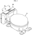
- FIG. 1 is a view illustrating a compressor according to an embodiment.
- FIG. 2 is a cross-sectional view schematically illustrating the compressor with a controller disconnected, according to an embodiment.
- FIG. 3 is a view illustrating a compressor case and the controller separated, according to an embodiment.
- the compressor may include a compression mechanism 20 that compresses a refrigerant through the reciprocating motion of a piston 23, and a compressor case 10 in which a motor 30, an electric mechanism that drives the compression mechanism 20, is provided.
- the compressor case 10 may be a sealed case.
- the compressor may include a frame 12 for securing various components within the compressor case 10, the compression mechanism 20 installed on an upper side of the frame 12, the motor 30 which is the electric mechanism mounted installed on a lower side of the frame 12 for driving the compression mechanism 20, and a rotating shaft 30 disposed in a vertical direction to transmit a driving force of the motor 30 to the compression mechanism 20 and rotatably supported on an axial support 12a of the frame 12.
- the compression mechanism 20 may include a cylinder 21 that forms a compression space for the refrigerant and is secured to the frame 12, the piston 23 that advances and retreats inside the cylinder 21 and compresses the refrigerant, and a connecting rod 25 that connects an eccentric portion 41 and the piston 23.
- the motor 30 may be a brushless direct current (BLDC) motor.
- the motor 30 may be a DC motor using direct current (DC) voltage, but without brushes.
- the motor 30 may include a stator 33 fixed to the frame 12, and a rotor 31 rotating on an inner side of the stator 33.
- the rotor 31 may include a hollow space in which the rotating shaft 40 may be received.
- the rotating shaft 40 may be press-fitted into the hollow space of the rotor 31 and may rotate together with the rotor 31.
- the rotating shaft 40 may include the eccentric portion 41 that is eccentric to the central axis of rotation.
- the eccentric portion 41 may be connected to the piston 23 by the connecting rod 25 to allow a rotational movement of the rotating shaft 40 to be converted into a linear translational movement of the piston 23.
- the compressor case 10 may include a connection terminal 11 for supplying power to the motor 30.
- the connection terminal 11 may be provided in a plurality.
- a cluster 120 (see FIG. 4 ) of a controller 100, which will be described below, may be connected to the plurality of connection terminals 11 to control the power supplied to the motor 30 through the controller 100.
- the compressor case 10 may include a controller assembly 13 in which the controller 100 is assembled.
- the controller assembly 13 may be formed around the plurality of connection terminals 11.
- the controller assembly 13 may be formed from a steel material.
- the controller assembly 13 may include a first fastening hole 15 to which the controller 100 is fastened by a fastening member B.
- the controller assembly 13 may include an assembling hook 17 that is inserted into and assembled with the controller 100.
- the first fastening hole 15 and the assembling hook 17 will be described in more detail below.
- the compressor may include the controller 100 that is fastened to the compressor case 10 and is configured to control power supplied to the motor 30 arranged within the compressor case 10.
- the controller 100 may include a controller case 110 forming an exterior.
- the controller case 110 may include a first case 111, a second case 113, and a side case 117.
- the first case 111 is a portion that is assembled to the compressor case 10 and may include a cluster assembly 130 to which the cluster 120 is assembled.
- the cluster assembly 130 will be described in more detail below.
- the first case 111 may include a compressor assembly 140 that is assembled to the compressor case 10.
- the compressor assembly 140 may be assembled to the controller assembly 13 formed in the compressor case 10.
- the compressor assembly 140 may be formed to have a square shape around the cluster assembly 130 of the first case 111.
- the compressor assembly 140 may include a second fastening hole 141 that is fastened to the first fastening hole 15 of the controller assembly 13 by the fastening member B.
- the compressor assembly 140 may include an assembling hole 143 into which the assembling hook 17 of the controller assembly 13 is inserted and assembled.
- the second fastening hole 141 and the assembling hole 143 will be described in more detail below.
- the compressor assembly 140 may include a flange 145 having a square-shaped edge protruding toward the compressor case 10.
- the flange 145 may be formed over the entire square-shape edge.
- the flange 145 may be in close contact with the compressor case 10 to ensure that the cluster assembly 130 is sealed from the outside when the controller 100 is assembled to the compressor case 10. Because the cluster assembly 130 is sealed from the outside by the flange 145, it is possible to prevent insects and the like from entering the cluster 120 (see FIG. 4 ) through the cluster assembly 130.
- the cluster assembly 130 being sealed from the outside by the flange 145, water splashing into the cluster 120 (see FIG. 4 ) through the cluster assembly 130 may be prevented.
- the compressor in the event that the compressor is used in a refrigerator, the compressor is placed in a machine room positioned at a lower portion of the refrigerator, water may fall to the floor and splash onto the cluster assembly 130.
- the flange 145 may seal the cluster assembly 130 from the outside, thereby preventing water from splashing and entering the cluster 120 (see FIG. 4 ).
- FIG. 4 is a view showing the controller case of the controller being separated from the controller according to an embodiment.
- FIG. 5 is an enlarged view showing the cluster assembly according to an embodiment.
- the controller 100 may include the cluster 120 connected to the plurality of connection terminals 11 (see FIG. 3 ) formed on the compressor case 10.
- the cluster 120 may connect the controller 100 and the compressor case 10 (see FIG. 3 ) to control the power supplied to the motor 30 (see FIG. 2 ) arranged inside the compressor case 10 (see FIG. 3 ).
- the cluster 120 may include a wire connector 123 connected to a board 115 assembled in the second case 113 by a wire W.
- the wire connector 123 may be provided on a rear side of the cluster 120.
- the wire W connecting the board 115 and the cluster 120 may be provided in a plurality. Three wires W are shown in the drawings, but the present disclosure is not limited thereto.
- the wire connectors 123 may be provided in a number corresponding to the number of wires W.
- the cluster 120 may include a connection hole 125 connected to the connection terminals 11 of the compressor case 10 (see FIG. 3 ).
- the connection holes 125 may be provided in a plurality.
- the plurality of connection terminals 11 (see FIG. 3 ) to which the connection holes 125 are connected may also be formed.
- the connection holes 125 and the connection terminals 11 (see FIG. 3 ) may be formed to have a corresponding number of wires W.
- three connection holes 125 and three connection terminals 11 are shown, but the present disclosure is not limited thereto.
- the cluster 120 may include a fixing groove 127 (see FIG. 6 ) secured to a first hook 133 of the cluster assembly 130.
- the fixing groove 127 may be provided on a lower surface of the cluster 120.
- the fixing groove 127 may be provided in a front portion of the lower surface of the cluster 120. The configuration in which the first hook 133 is fixed to the fixing groove 127 will be described in more detail below.
- the controller 100 may include the cluster assembly 130 in which the cluster 120 is assembled.
- the cluster assembly 130 may be formed in the first case 111.
- the cluster assembly 130 may be formed on an interior of the first case 111.
- the cluster assembly 130 may be formed on the interior of the case 110 to prevent the cluster 120 from being exposed to the outside. By preventing the cluster 120 from being exposed to the outside, insects and the like may be prevented from infiltrating the cluster 120.
- the cluster assembly 130 may include a plurality of hooks 131 for securing the cluster 120. Although the plurality of hooks 131 is shown in the drawings as forming three hooks, but the present disclosure is not limited thereto.
- the plurality of hooks 131 may include the first hook 133 that secures the front portion of the lower surface 121 (see FIG. 6 ) of the cluster 120.
- the first hook 133 may engage the fixing groove 127 formed on the front portion of the lower surface 121 of the cluster 120 to secure the cluster 120.
- the plurality of hooks 131 may include a pair of second hooks 135 that secure both side surfaces of a central portion of the lower surface 121 (see FIG. 6 ) of the cluster 120.
- the pair of second hooks 135 may be engaged with the lower surface 121 of the cluster 120 to secure the cluster 120.
- the cluster 120 is assembled by engaging the plurality of hooks 131 formed in the cluster assembly 130, the cluster 120 may be easily assembled to the cluster assembly 130.
- the cluster assembly 130 may include a guide 137 provided to guide the assembly of the cluster 120.
- the guide 137 may be formed to have a U-shape with an open top based on the lower surface of the case 110.
- the guide 137 may be formed to be recessed from an inside of the first case 111 toward the outside.
- the plurality of hooks 131 may be provided inside the guide 137.
- the first hook 133 of the plurality of hooks 131 may be positioned at a lower portion of the guide 137.
- a pair of second hooks 135 of the plurality of hooks 131 may be positioned at an upper portion of the first hook 133 inside the guide 137.
- the wire W connected to the cluster 120 may be connected to the board 115 within the controller 100 through the open top of the guide 137.
- the cluster assembly 130 may include a plurality of openings 139 formed at positions corresponding to the plurality of connection holes 125 formed in the cluster 120.
- the plurality of connection terminals 11 may be connected to a plurality of connection holes 125 through the plurality of openings 139.
- connection holes 125 and three openings 139 are shown in the drawings, the present disclosure is not limited thereto.
- FIG. 6 is a view of a cluster being inserted horizontally into the cluster assembly, according to an embodiment.
- FIG. 7 is a cross-sectional view illustrating the cluster being inserted horizontally into the cluster assembly, according to an embodiment.
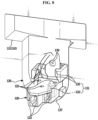
- FIG. 8 is a view illustrating the cluster according to an embodiment being inserted horizontally into the cluster assembly and then guided by a guide to be rotated vertically.
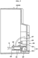
- FIG. 9 is a cross-sectional view illustrating the cluster, according to an embodiment, being inserted horizontally into the cluster assembly and then guided by the guide to be rotated vertically.
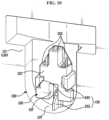
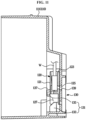
- FIG. 10 is a view illustrating the cluster according to an embodiment being guided by the guide, rotated vertically, and secured to a plurality of hooks.
- FIG. 11 is a cross-sectional view illustrating the cluster, according to an embodiment, being guided by the guide, rotated vertically, and secured to the plurality of hooks.
- the cluster 120 may be horizontally inserted into the cluster assembly 130 based on the lower surface of the case 110.
- the cluster 120 may be horizontally inserted into the lower portion of the guide 137 based on the lower surface of the case 110.
- the cluster 120 may be inserted into the cluster assembly 130 such that a portion of the first hook 133 is received in the fixing groove 127 formed on the front portion of the lower surface 121 of the cluster 120.
- the cluster 120 when the cluster 120 is horizontally inserted into the cluster assembly 130 with respect to the lower surface of the case 110, a portion of the first hook 133 may be received in the fixing groove 127.
- the cluster 120 When the front surface of the cluster 120 contacts the recessed surface of the guide 137 by inserting the cluster 120 so that a portion of the first hook 133 is received in the fixing groove 127, the cluster 120 may be rotated vertically. In other words, the cluster 120 may be rotated vertically so that the front side in which the fixing groove 127 is formed is located at the lower portion of the guide 137, and the rear side in which the wire connector 123 is formed is located at the upper portion of the guide 137.
- a front side of the cluster 120 may be a lower side of the cluster 120 as the cluster 120 is rotated.
- the cluster 120 may contact the recessed surface of the guide 137.
- the upper surface of the cluster 120 in which the connection hole 125 is formed may contact the recessed surface of the guide 137.
- the cluster 120 may be secured by inserting the front portion of the lower surface 121 into the first hook 133.
- the cluster 120 may be secured by engaging each side of the central portion of the lower surface 121 into each of the pair of second hooks 135.
- the cluster 120 may be received entirely within the guide 137.
- the cluster 120 when the cluster 120 is rotated vertically after the cluster 120 is inserted horizontally so that the front surface of the cluster 120 contacts the recessed surface of the guide 137, the cluster 120 may be assembled by securing it to the plurality of hooks 131. Since the cluster 120 may be assembled to the cluster assembly 130 through a simple operation as described above, assembly of the cluster 120 may be facilitated.
- the plurality of connection holes 125 formed in the cluster 120 may be in a state where they may be connected to the plurality of connection terminals 11 formed in the compressor case 10 through the plurality of openings 139 formed in the cluster assembly 130.
- FIG. 12 is a view showing the controller according to an embodiment being assembled to the compressor case.
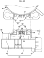
- FIG. 13 is a view showing the controller according to an embodiment being assembled in the compressor case.
- the controller 100 may be moved toward the compressor case 10 such that the plurality of connection terminals 11 of the compressor case 10 is inserted into the plurality of connection holes 125 of the cluster 120.
- a position at which the controller 100 is assembled to the compressor case 10 may be guided.
- the position at which the controller 100 is assembled to the compressor case 10 may be guided.
- the controller assembly 13 formed in the compressor case 11 may be in a position to be assembled to the compressor assembly 140 formed in the controller case 110 without the need to adjust the position of the controller 100.
- the first fastening hole 15 of the controller assembly 13 may be located at a position corresponding to the second fastening hole 141 of the compressor assembly 140.
- the assembling hook 17 of the controller assembly 13 may be inserted into and secured to the assembling hole 143 of the compressor assembly 140.
- the first fastening holes 15 and the second fastening holes 141 may be fastened by the fastening member B.
- the controller 100 may be guided to a position where it may be assembled to the compressor case 10 without separate position adjustment, thereby facilitating assembly of the controller 100 to the compressor case 10.
- the flange 145 of the controller 100 may be in close contact with the compressor case 10, so that the cluster assembly 130 may be sealed from the outside.
- insects and the like may be prevented from entering the cluster 120 through the cluster assembly 130 (see FIG. 2 ).
- the assembling hook 17 is arranged on the controller assembly 13 formed from the steel material, the assembling hole 143 in which the assembling hook 17 is assembled is provided on the compressor assembly 140 of the controller 100 that is assembled to the controller assembly portion 13, the controller 100 may be firmly assembled to the compressor case 10.
Landscapes
- Engineering & Computer Science (AREA)
- Mechanical Engineering (AREA)
- General Engineering & Computer Science (AREA)
- Power Engineering (AREA)
- Physics & Mathematics (AREA)
- Thermal Sciences (AREA)
- Compressor (AREA)
Abstract
Description
- The disclosure relates to a compressor having an improved case structure for a controller controlling a motor.
- In general, a compressor is a mechanical device that compresses air, refrigerant, or various other working gases to increase pressure by receiving power from a power generator, such as an electric motor or turbine and, and is widely used in household appliances, such as refrigerators and air conditioners, as well as in various industries.
- Compressors may be classified into different types depending on their compression method and sealing structure.
- Depending on the compression method, compressors are divided into reciprocating compressors, rotary compressors, and scroll compressors.
- Among reciprocating compressors, for example, a sealed reciprocating compressor includes a compression mechanism that compresses refrigerant through the reciprocating motion of a piston and an electric mechanism that drives the compression mechanism, wherein the compression mechanism and the electric mechanism are installed in a single sealed case.
- A compressor may include a compressor case, a motor which is an electric mechanism provided inside the compressor case, and a controller connected to the compressor case to control the motor.
- The controller may include a case forming an exterior, a board controlling the power supplied to the motor of the compressor, a cluster connected to a connection terminal provided in the compressor case, and a wire connecting the board and the connection terminal. Exposing the cluster to the outside of the case may cause problems with insect entering the cluster.
- In addition, the controller may require assembly of the controller case to compressor case after connecting the cluster to the connection terminal, which may complicate the assembly by dividing it into two steps.
- Provided is a compressor having an improved structure of a controller case such that a cluster is assembled within the controller case.
- Further, provided is a compressor in which the structure of a controller case is improved so as to facilitate assembly of a cluster.
- Further, provided is a compressor in which the structure of a controller case and a compressor case is improved so as to facilitate assembly of a controller to the compressor case.
- According to an embodiment of the disclosure, a compressor includes a compressor case equipped with a BLDC motor therein and a connection terminal for receiving power from the BLDC motor, and a controller fastened to the compressor case to control the power supplied to the BLDC motor, wherein the controller includes a cluster connected to the connection terminal, and a controller case fastened to the compressor case and including a cluster assembly therein to which the cluster is assembled to prevent the cluster from being exposed to the outside, wherein the cluster assembly includes a plurality of hooks for securing the cluster, and a guide configured to guide so that the cluster is inserted horizontally based on a lower surface of the controller case and then rotated and secured vertically.
- The plurality of hooks may include a first hook securing a front portion of a lower surface of the cluster and a pair of second hooks securing both sides of a central portion of the lower surface of the cluster.
- The cluster may include a wire connector connected to a board inside the controller by a wire, a connection hole connected to the connection terminal, and a fixing groove into which the cluster is inserted horizontally based on the lower surface of the controller case and then rotated and secured to the first hook.
- The wires may be provided in a plurality, and the connection holes and the connection terminals may be formed in a plurality corresponding to the number of the wires.
- The cluster assembly may include a plurality of openings formed at positions corresponding to the plurality of connection holes and allowing the plurality of connection terminals to be connected to the plurality of connection holes.
- The guide may be formed to be recessed from an inside of the controller case toward the outside so as to have a U-shape with an open top based on the lower surface of the controller case.
- The first hook may be positioned at a lower portion of the guide, and the pair of second hooks may be positioned at an upper portion of the first hook inside the guide.
- The cluster may be inserted into the lower portion of the guide to allow a portion of the first hook to be received in the fixing groove, and then rotated to allow the cluster to be received entirely within the guide, so that the fixing groove may be secured to the first hook and both sides of the central portion of the cluster are secured to the pair of second hooks.
- The wire may be connected to the board inside the controller through the open top of the guide.
- The compressor case may include a controller assembly to which the controller is assembled, and the controller case may include a compressor assembly to which the controller assembly is assembled.
- The controller assembly may be formed from a steel material and around the connection terminal, and include a first fastening hole to which the compressor assembly is fastened by a fastening member, and an assembling hook to be inserted into the compressor assembly.
- The compressor assembly may be formed around the cluster assembly, and include a second fastening hole fastened to the first fastening hole by the fastening member, and an assembling hole into which the assembling hook is inserted and assembled.
- A position at which the controller is assembled to the compressor case may be guided based on the cluster being connected to the connection terminal.
- In response to the cluster being connected to the connection terminal, the assembling hook may be inserted into the assembling hole to be assembled, and the positions of the first fastening hole and the second fastening hole may be aligned, thereby being fastened by the fastening member.
- The compressor assembly may be formed to have a square-shape around the cluster assembly, and include a flange having a square-shaped edge protruding toward the compressor case to ensure that the cluster assembly is sealed from the outside when the controller is assembled to the compressor case.
- According to one or more embodiments, the cluster may be assembled within the interior of the controller case to prevent insect entering the cluster.
- Further, according to one or more embodiments, the structure of the cluster assembly provided inside the controller case may be improved to facilitate assembly of the cluster.
- Further, according to one or more embodiments, when assembling the controller to the compressor case, the cluster may be connected to the connection terminal and the controller case may be assembled to the compressor case at the same time to facilitate assembly.
- Further, according to one or more embodiments, when the controller case is assembled to the compressor case, the space between the controller case and the compressor case may be sealed to prevent insect infiltration and water splashing into the interior.
- Further, according to one or more embodiments, the controller may be assembled securely to the compressor case.
-
-
FIG. 1 is a view illustrating a compressor according to an embodiment. -
FIG. 2 is a cross-sectional view schematically illustrating the compressor with a controller disconnected, according to an embodiment. -
FIG. 3 is a view illustrating a compressor case and the controller separated, according to an embodiment. -
FIG. 4 is a view illustrating a controller case of the controller separated from the controller according to an embodiment. -
FIG. 5 is an enlarged view illustrating a cluster assembly according to an embodiment. -
FIG. 6 is a view of a cluster being inserted horizontally into the cluster assembly, according to an embodiment. -
FIG. 7 is a cross-sectional view illustrating the cluster being inserted horizontally into the cluster assembly, according to an embodiment. -
FIG. 8 is a view illustrating the cluster according to an embodiment being inserted horizontally into the cluster assembly and then guided by a guide to be rotated vertically. -
FIG. 9 is a cross-sectional view illustrating the cluster, according to an embodiment, being inserted horizontally into the cluster assembly and then guided by the guide to be rotated vertically. -
FIG. 10 is a view illustrating the cluster according to an embodiment being guided by the guide, rotated vertically, and secured to a plurality of hooks. -
FIG. 11 is a cross-sectional view illustrating the cluster, according to an embodiment, being guided by the guide, rotated vertically, and secured to the plurality of hooks. -
FIG. 12 is a view of the controller, according to an embodiment, being assembled to the compressor case. -
FIG. 13 is a view illustrating the controller according to an embodiment assembled in the compressor case. - Embodiments described in the disclosure and configurations shown in the drawings are merely examples of the embodiments of the disclosure and may be modified in various different ways at the time of filing of the present application to replace the embodiments and drawings of the disclosure.
- In connection with the description of the drawings, similar reference numerals may be used for similar or related components.
- Also, the terms used herein are used to describe the embodiments and are not intended to limit and/or restrict the disclosure. The singular forms "a," "an" and "the" are intended to include the plural forms as well, unless the context clearly indicates otherwise. In this disclosure, the terms "including", "having", and the like are used to specify features, figures, steps, operations, elements, components, or combinations thereof, but do not preclude the presence or addition of one or more of the features, figures, steps, operations, elements, components, or combinations thereof.
- It will be understood that, although the terms "first", "second", "primary", "secondary", etc., may be used herein to describe various elements, but elements are not limited by these terms. These terms are only used to distinguish one element from another element. For example, without departing from the scope of the disclosure, a first element may be termed as a second element, and a second element may be termed as a first element. The term of "and/or" includes a plurality of combinations of relevant items or any one item among a plurality of relevant items.
- The terms "front end", "rear end", "upper", "lower" , "front", "rear", "top", and "bottom" as used in the following description may be defined with reference to the drawings, and the shape and position of each component is not limited by these terms.
- Embodiments of the present disclosure will be described in detail below with reference to the accompanying drawings.
-
FIG. 1 is a view illustrating a compressor according to an embodiment.FIG. 2 is a cross-sectional view schematically illustrating the compressor with a controller disconnected, according to an embodiment.FIG. 3 is a view illustrating a compressor case and the controller separated, according to an embodiment. - As shown in
FIGS. 1 to 3 , the compressor may include acompression mechanism 20 that compresses a refrigerant through the reciprocating motion of apiston 23, and acompressor case 10 in which amotor 30, an electric mechanism that drives thecompression mechanism 20, is provided. Thecompressor case 10 may be a sealed case. - The compressor may include a
frame 12 for securing various components within thecompressor case 10, thecompression mechanism 20 installed on an upper side of theframe 12, themotor 30 which is the electric mechanism mounted installed on a lower side of theframe 12 for driving thecompression mechanism 20, and arotating shaft 30 disposed in a vertical direction to transmit a driving force of themotor 30 to thecompression mechanism 20 and rotatably supported on anaxial support 12a of theframe 12. - The
compression mechanism 20 may include acylinder 21 that forms a compression space for the refrigerant and is secured to theframe 12, thepiston 23 that advances and retreats inside thecylinder 21 and compresses the refrigerant, and a connectingrod 25 that connects aneccentric portion 41 and thepiston 23. - The
motor 30 may be a brushless direct current (BLDC) motor. In other words, themotor 30 may be a DC motor using direct current (DC) voltage, but without brushes. - The
motor 30 may include astator 33 fixed to theframe 12, and arotor 31 rotating on an inner side of thestator 33. Therotor 31 may include a hollow space in which therotating shaft 40 may be received. The rotatingshaft 40 may be press-fitted into the hollow space of therotor 31 and may rotate together with therotor 31. - The rotating
shaft 40 may include theeccentric portion 41 that is eccentric to the central axis of rotation. Theeccentric portion 41 may be connected to thepiston 23 by the connectingrod 25 to allow a rotational movement of therotating shaft 40 to be converted into a linear translational movement of thepiston 23. - The
compressor case 10 may include aconnection terminal 11 for supplying power to themotor 30. Theconnection terminal 11 may be provided in a plurality. A cluster 120 (seeFIG. 4 ) of acontroller 100, which will be described below, may be connected to the plurality ofconnection terminals 11 to control the power supplied to themotor 30 through thecontroller 100. - The
compressor case 10 may include acontroller assembly 13 in which thecontroller 100 is assembled. Thecontroller assembly 13 may be formed around the plurality ofconnection terminals 11. Thecontroller assembly 13 may be formed from a steel material. - The
controller assembly 13 may include afirst fastening hole 15 to which thecontroller 100 is fastened by a fastening member B. Thecontroller assembly 13 may include an assemblinghook 17 that is inserted into and assembled with thecontroller 100. Thefirst fastening hole 15 and the assemblinghook 17 will be described in more detail below. - The compressor may include the
controller 100 that is fastened to thecompressor case 10 and is configured to control power supplied to themotor 30 arranged within thecompressor case 10. - The
controller 100 may include acontroller case 110 forming an exterior. Thecontroller case 110 may include afirst case 111, asecond case 113, and aside case 117. - The
first case 111 is a portion that is assembled to thecompressor case 10 and may include acluster assembly 130 to which thecluster 120 is assembled. Thecluster assembly 130 will be described in more detail below. - The
first case 111 may include acompressor assembly 140 that is assembled to thecompressor case 10. Thecompressor assembly 140 may be assembled to thecontroller assembly 13 formed in thecompressor case 10. Thecompressor assembly 140 may be formed to have a square shape around thecluster assembly 130 of thefirst case 111. - The
compressor assembly 140 may include asecond fastening hole 141 that is fastened to thefirst fastening hole 15 of thecontroller assembly 13 by the fastening member B. Thecompressor assembly 140 may include an assemblinghole 143 into which the assemblinghook 17 of thecontroller assembly 13 is inserted and assembled. Thesecond fastening hole 141 and the assemblinghole 143 will be described in more detail below. - The
compressor assembly 140 may include aflange 145 having a square-shaped edge protruding toward thecompressor case 10. Theflange 145 may be formed over the entire square-shape edge. Theflange 145 may be in close contact with thecompressor case 10 to ensure that thecluster assembly 130 is sealed from the outside when thecontroller 100 is assembled to thecompressor case 10. Because thecluster assembly 130 is sealed from the outside by theflange 145, it is possible to prevent insects and the like from entering the cluster 120 (seeFIG. 4 ) through thecluster assembly 130. - In addition, based on the
cluster assembly 130 being sealed from the outside by theflange 145, water splashing into the cluster 120 (seeFIG. 4 ) through thecluster assembly 130 may be prevented. In other words, in the event that the compressor is used in a refrigerator, the compressor is placed in a machine room positioned at a lower portion of the refrigerator, water may fall to the floor and splash onto thecluster assembly 130. Theflange 145 may seal thecluster assembly 130 from the outside, thereby preventing water from splashing and entering the cluster 120 (seeFIG. 4 ). -
FIG. 4 is a view showing the controller case of the controller being separated from the controller according to an embodiment.FIG. 5 is an enlarged view showing the cluster assembly according to an embodiment. - As shown in
FIGS. 4 and5 , thecontroller 100 may include thecluster 120 connected to the plurality of connection terminals 11 (seeFIG. 3 ) formed on thecompressor case 10. Thecluster 120 may connect thecontroller 100 and the compressor case 10 (seeFIG. 3 ) to control the power supplied to the motor 30 (seeFIG. 2 ) arranged inside the compressor case 10 (seeFIG. 3 ). - The
cluster 120 may include awire connector 123 connected to aboard 115 assembled in thesecond case 113 by a wire W. Thewire connector 123 may be provided on a rear side of thecluster 120. The wire W connecting theboard 115 and thecluster 120 may be provided in a plurality. Three wires W are shown in the drawings, but the present disclosure is not limited thereto. Thewire connectors 123 may be provided in a number corresponding to the number of wires W. - The
cluster 120 may include aconnection hole 125 connected to theconnection terminals 11 of the compressor case 10 (seeFIG. 3 ). The connection holes 125 may be provided in a plurality. In response to the plurality of connection holes 125 being formed, the plurality of connection terminals 11 (seeFIG. 3 ) to which the connection holes 125 are connected may also be formed. In other words, the connection holes 125 and the connection terminals 11 (seeFIG. 3 ) may be formed to have a corresponding number of wires W. In the drawings, threeconnection holes 125 and three connection terminals 11 (seeFIG. 3 ) are shown, but the present disclosure is not limited thereto. - The
cluster 120 may include a fixing groove 127 (seeFIG. 6 ) secured to afirst hook 133 of thecluster assembly 130. The fixinggroove 127 may be provided on a lower surface of thecluster 120. The fixinggroove 127 may be provided in a front portion of the lower surface of thecluster 120. The configuration in which thefirst hook 133 is fixed to the fixinggroove 127 will be described in more detail below. - The
controller 100 may include thecluster assembly 130 in which thecluster 120 is assembled. Thecluster assembly 130 may be formed in thefirst case 111. Thecluster assembly 130 may be formed on an interior of thefirst case 111. Thecluster assembly 130 may be formed on the interior of thecase 110 to prevent thecluster 120 from being exposed to the outside. By preventing thecluster 120 from being exposed to the outside, insects and the like may be prevented from infiltrating thecluster 120. - The
cluster assembly 130 may include a plurality ofhooks 131 for securing thecluster 120. Although the plurality ofhooks 131 is shown in the drawings as forming three hooks, but the present disclosure is not limited thereto. - The plurality of
hooks 131 may include thefirst hook 133 that secures the front portion of the lower surface 121 (seeFIG. 6 ) of thecluster 120. When thecluster 120 is assembled to thecluster assembly 130, thefirst hook 133 may engage the fixinggroove 127 formed on the front portion of thelower surface 121 of thecluster 120 to secure thecluster 120. - The plurality of
hooks 131 may include a pair ofsecond hooks 135 that secure both side surfaces of a central portion of the lower surface 121 (seeFIG. 6 ) of thecluster 120. When thecluster 120 is assembled to thecluster assembly 130, the pair ofsecond hooks 135 may be engaged with thelower surface 121 of thecluster 120 to secure thecluster 120. - Because the
cluster 120 is assembled by engaging the plurality ofhooks 131 formed in thecluster assembly 130, thecluster 120 may be easily assembled to thecluster assembly 130. - The
cluster assembly 130 may include aguide 137 provided to guide the assembly of thecluster 120. Theguide 137 may be formed to have a U-shape with an open top based on the lower surface of thecase 110. Theguide 137 may be formed to be recessed from an inside of thefirst case 111 toward the outside. The plurality ofhooks 131 may be provided inside theguide 137. Thefirst hook 133 of the plurality ofhooks 131 may be positioned at a lower portion of theguide 137. A pair ofsecond hooks 135 of the plurality ofhooks 131 may be positioned at an upper portion of thefirst hook 133 inside theguide 137. - The wire W connected to the
cluster 120 may be connected to theboard 115 within thecontroller 100 through the open top of theguide 137. - The
cluster assembly 130 may include a plurality ofopenings 139 formed at positions corresponding to the plurality of connection holes 125 formed in thecluster 120. The plurality of connection terminals 11 (seeFIG. 3 ) may be connected to a plurality of connection holes 125 through the plurality ofopenings 139. - Although three
connection holes 125 and threeopenings 139 are shown in the drawings, the present disclosure is not limited thereto. - Next, with reference to
FIGS. 6 to 11 , the operation of assembling thecluster 120 into thecluster assembly 130 will be described in more detail. -
FIG. 6 is a view of a cluster being inserted horizontally into the cluster assembly, according to an embodiment.FIG. 7 is a cross-sectional view illustrating the cluster being inserted horizontally into the cluster assembly, according to an embodiment.FIG. 8 is a view illustrating the cluster according to an embodiment being inserted horizontally into the cluster assembly and then guided by a guide to be rotated vertically.FIG. 9 is a cross-sectional view illustrating the cluster, according to an embodiment, being inserted horizontally into the cluster assembly and then guided by the guide to be rotated vertically.FIG. 10 is a view illustrating the cluster according to an embodiment being guided by the guide, rotated vertically, and secured to a plurality of hooks.FIG. 11 is a cross-sectional view illustrating the cluster, according to an embodiment, being guided by the guide, rotated vertically, and secured to the plurality of hooks. - As shown in
FIGS. 6 and7 , thecluster 120 may be horizontally inserted into thecluster assembly 130 based on the lower surface of thecase 110. Thecluster 120 may be horizontally inserted into the lower portion of theguide 137 based on the lower surface of thecase 110. In this case, thecluster 120 may be inserted into thecluster assembly 130 such that a portion of thefirst hook 133 is received in the fixinggroove 127 formed on the front portion of thelower surface 121 of thecluster 120. - As shown in
FIGS. 8 and9 , when thecluster 120 is horizontally inserted into thecluster assembly 130 with respect to the lower surface of thecase 110, a portion of thefirst hook 133 may be received in the fixinggroove 127. When the front surface of thecluster 120 contacts the recessed surface of theguide 137 by inserting thecluster 120 so that a portion of thefirst hook 133 is received in the fixinggroove 127, thecluster 120 may be rotated vertically. In other words, thecluster 120 may be rotated vertically so that the front side in which the fixinggroove 127 is formed is located at the lower portion of theguide 137, and the rear side in which thewire connector 123 is formed is located at the upper portion of theguide 137. - As shown in
FIGS. 10 and11 , as thecluster 120 is rotated vertically, the fixinggroove 127 may be inserted into thefirst hook 133, and the front portion of thelower surface 121 of thecluster 120 may be secured to thefirst hook 133. In the drawings, a front side of thecluster 120 may be a lower side of thecluster 120 as thecluster 120 is rotated. - In response to the
cluster 120 being rotated by 90 degrees, thecluster 120 may contact the recessed surface of theguide 137. In other words, when thecluster 120 is rotated by 90 degrees, the upper surface of thecluster 120 in which theconnection hole 125 is formed may contact the recessed surface of theguide 137. At this time, thecluster 120 may be secured by inserting the front portion of thelower surface 121 into thefirst hook 133. In addition, thecluster 120 may be secured by engaging each side of the central portion of thelower surface 121 into each of the pair of second hooks 135. When thecluster 120 is secured by the plurality ofhooks 131, thecluster 120 may be received entirely within theguide 137. - In other words, when the
cluster 120 is rotated vertically after thecluster 120 is inserted horizontally so that the front surface of thecluster 120 contacts the recessed surface of theguide 137, thecluster 120 may be assembled by securing it to the plurality ofhooks 131. Since thecluster 120 may be assembled to thecluster assembly 130 through a simple operation as described above, assembly of thecluster 120 may be facilitated. - Once the
cluster 120 is assembled to thecluster assembly 130, the plurality of connection holes 125 formed in thecluster 120 may be in a state where they may be connected to the plurality ofconnection terminals 11 formed in thecompressor case 10 through the plurality ofopenings 139 formed in thecluster assembly 130. - Next, with reference to
FIGS. 12 and13 , the operation of assembling thecontroller 100 to thecompressor case 10 will be described in more detail. -
FIG. 12 is a view showing the controller according to an embodiment being assembled to the compressor case.FIG. 13 is a view showing the controller according to an embodiment being assembled in the compressor case. - As shown in
FIG. 12 , with thecluster 120 assembled to thecluster assembly 130, thecontroller 100 may be moved toward thecompressor case 10 such that the plurality ofconnection terminals 11 of thecompressor case 10 is inserted into the plurality of connection holes 125 of thecluster 120. - As shown in
FIG. 13 , once the plurality ofconnection terminals 11 of thecompressor case 10 is inserted into the plurality of connection holes 125 of thecluster 120, a position at which thecontroller 100 is assembled to thecompressor case 10 may be guided. In other words, based on the plurality of connection holes 125 of thecluster 120 and the plurality ofconnection terminals 11 of thecompressor case 10 being connected, the position at which thecontroller 100 is assembled to thecompressor case 10 may be guided. - As a result, when the plurality of connection holes 125 of the
cluster 120 and the plurality ofconnection terminals 11 of thecompressor case 10 are connected, thecontroller assembly 13 formed in thecompressor case 11 may be in a position to be assembled to thecompressor assembly 140 formed in thecontroller case 110 without the need to adjust the position of thecontroller 100. - In other words, the
first fastening hole 15 of thecontroller assembly 13 may be located at a position corresponding to thesecond fastening hole 141 of thecompressor assembly 140. In addition, the assemblinghook 17 of thecontroller assembly 13 may be inserted into and secured to the assemblinghole 143 of thecompressor assembly 140. As described above, based on the assemblinghook 17 of thecontroller assembly 13 being inserted into the assemblinghole 143 of thecompressor assembly 140 and the positions of thefirst fastening hole 15 of thecontroller assembly 13 and thesecond fastening hole 141 of thecompressor assembly 140 being aligned, the first fastening holes 15 and the second fastening holes 141 may be fastened by the fastening member B. - As described above, in response to the
cluster 120 being connected to the plurality ofconnection terminals 11 of thecompressor case 10, thecontroller 100 may be guided to a position where it may be assembled to thecompressor case 10 without separate position adjustment, thereby facilitating assembly of thecontroller 100 to thecompressor case 10. - When the
controller 100 is assembled to thecompressor case 10, theflange 145 of thecontroller 100 may be in close contact with thecompressor case 10, so that thecluster assembly 130 may be sealed from the outside. When thecluster assembly 130 is sealed from the outside by theflange 145, insects and the like may be prevented from entering thecluster 120 through the cluster assembly 130 (seeFIG. 2 ). - Furthermore, since the assembling
hook 17 is arranged on thecontroller assembly 13 formed from the steel material, the assemblinghole 143 in which the assemblinghook 17 is assembled is provided on thecompressor assembly 140 of thecontroller 100 that is assembled to thecontroller assembly portion 13, thecontroller 100 may be firmly assembled to thecompressor case 10. - Although certain example embodiments are illustrated and described above, the present disclosure is not limited to the certain embodiments, various applications may of course be performed by those skilled in the art without deviating from what is claimed in the scope of claims, and such applications should not be understood separately from the technical idea or prospects herein.
Claims (15)
- A compressor, comprising:a compressor case equipped with a brushless direct current (BLDC) motor therein and a connection terminal for receiving power from the BLDC motor; anda controller fastened to the compressor case to control the power supplied to the BLDC motor;wherein the controller comprises:a cluster connected to the connection terminal, anda controller case fastened to the compressor case and including a cluster assembly therein to which the cluster is assembled to prevent the cluster from being exposed to the outside,wherein the cluster assembly comprises:a plurality of hooks for securing the cluster, anda guide configured to guide so that the cluster is inserted horizontally based on a lower surface of the controller case and then rotated and secured vertically.
- The compressor of claim 1, wherein the plurality of hooks includes a first hook securing a front portion of a lower surface of the cluster and a pair of second hooks securing both sides of a central portion of the lower surface of the cluster.
- The compressor of claim 2, wherein the cluster includes a wire connector connected to a board inside the controller by a wire, a connection hole connected to the connection terminal, and a fixing groove into which the cluster is inserted horizontally based on the lower surface of the controller case and then rotated and secured to the first hook.
- The compressor of claim 3, wherein the wires are provided in a plurality, and the connection holes and the connection terminals are formed in a plurality corresponding to the number of the wires.
- The compressor of claim 4, wherein the cluster assembly includes a plurality of openings formed at positions corresponding to the plurality of connection holes and allowing the plurality of connection terminals to be connected to the plurality of connection holes.
- The compressor of claim 3, wherein the guide is formed to be recessed from an inside of the controller case toward the outside so as to have a U-shape with an open top based on the lower surface of the controller case.
- The compressor of claim 6, wherein the first hook is positioned at a lower portion of the guide, and the pair of second hooks is positioned at an upper portion of the first hook inside the guide.
- The compressor of claim 7, wherein the cluster is inserted into the lower portion of the guide to allow a portion of the first hook to be received in the fixing groove, and then rotated to allow the cluster to be received entirely within the guide, so that the fixing groove is secured to the first hook and both sides of the central portion of the cluster are secured to the pair of second hooks.
- The compressor of claim 6, wherein the wire is connected to the board inside the controller through the open top of the guide.
- The compressor of claim 1, wherein the compressor case includes a controller assembly to which the controller is assembled, and the controller case includes a compressor assembly to which the controller assembly is assembled.
- The compressor of claim 10, wherein the controller assembly is formed from a steel material and around the connection terminal, and includes a first fastening hole to which the compressor assembly is fastened by a fastening member, and an assembling hook to be inserted into the compressor assembly.
- The compressor of claim 11, wherein the compressor assembly is formed around the cluster assembly, and includes a second fastening hole fastened to the first fastening hole by the fastening member, and an assembling hole into which the assembling hook is inserted and assembled.
- The compressor of claim 12, wherein a position at which the controller is assembled to the compressor case is guided based on the cluster being connected to the connection terminal.
- The compressor of claim 13, wherein in response to the cluster being connected to the connection terminal, the assembling hook is inserted into the assembling hole to be assembled, and the positions of the first fastening hole and the second fastening hole are aligned, thereby being fastened by the fastening member.
- The compressor of claim 10, wherein the compressor assembly is formed to have a square-shape around the cluster assembly, and includes a flange having a square-shaped edge protruding toward the compressor case to ensure that the cluster assembly is sealed from the outside when the controller is assembled to the compressor case.
Applications Claiming Priority (2)
| Application Number | Priority Date | Filing Date | Title |
|---|---|---|---|
| KR1020220054329A KR20230154645A (en) | 2022-05-02 | 2022-05-02 | Compressor |
| PCT/KR2023/003061 WO2023214663A1 (en) | 2022-05-02 | 2023-03-07 | Compressor |
Publications (4)
| Publication Number | Publication Date |
|---|---|
| EP4461957A1 true EP4461957A1 (en) | 2024-11-13 |
| EP4461957A4 EP4461957A4 (en) | 2025-01-08 |
| EP4461957C0 EP4461957C0 (en) | 2025-09-24 |
| EP4461957B1 EP4461957B1 (en) | 2025-09-24 |
Family
ID=88646583
Family Applications (1)
| Application Number | Title | Priority Date | Filing Date |
|---|---|---|---|
| EP23799546.9A Active EP4461957B1 (en) | 2022-05-02 | 2023-03-07 | Compressor |
Country Status (5)
| Country | Link |
|---|---|
| US (1) | US20240392766A1 (en) |
| EP (1) | EP4461957B1 (en) |
| KR (1) | KR20230154645A (en) |
| CN (1) | CN118679321A (en) |
| WO (1) | WO2023214663A1 (en) |
Family Cites Families (7)
| Publication number | Priority date | Publication date | Assignee | Title |
|---|---|---|---|---|
| KR100598955B1 (en) * | 2004-07-24 | 2006-07-12 | 주식회사 대우일렉트로닉스 | Connection Jack Rotator of Display Device |
| JP2006161703A (en) * | 2004-12-08 | 2006-06-22 | Matsushita Electric Ind Co Ltd | Compressor terminal cover |
| KR100597291B1 (en) * | 2005-03-22 | 2006-07-04 | 엘지전자 주식회사 | Noise Reduction Structure of Linear Compressor |
| KR100690152B1 (en) * | 2006-01-16 | 2007-03-08 | 엘지전자 주식회사 | Linear Compressor Control Unit |
| JP2008102712A (en) * | 2006-10-18 | 2008-05-01 | Buffalo Inc | Media case |
| JP5594836B2 (en) * | 2010-11-24 | 2014-09-24 | 株式会社ヴァレオジャパン | Electric compressor |
| US10700471B2 (en) * | 2016-01-15 | 2020-06-30 | Embraco Indústria De Compressores E Soluções Em Refrigeração Ltda. | System, method and means for connecting and fixing an electronic control to an airtight compressor and an airtight compressor |
-
2022
- 2022-05-02 KR KR1020220054329A patent/KR20230154645A/en active Pending
-
2023
- 2023-03-07 WO PCT/KR2023/003061 patent/WO2023214663A1/en not_active Ceased
- 2023-03-07 CN CN202380023453.3A patent/CN118679321A/en active Pending
- 2023-03-07 EP EP23799546.9A patent/EP4461957B1/en active Active
-
2024
- 2024-08-07 US US18/797,020 patent/US20240392766A1/en active Pending
Also Published As
| Publication number | Publication date |
|---|---|
| KR20230154645A (en) | 2023-11-09 |
| EP4461957C0 (en) | 2025-09-24 |
| EP4461957B1 (en) | 2025-09-24 |
| WO2023214663A1 (en) | 2023-11-09 |
| CN118679321A (en) | 2024-09-20 |
| US20240392766A1 (en) | 2024-11-28 |
| EP4461957A4 (en) | 2025-01-08 |
Similar Documents
| Publication | Publication Date | Title |
|---|---|---|
| US7955141B2 (en) | Inverter connection terminal with cables attached to parts of the terminal projecting from upper and lower surfaces of a plate | |
| KR101319054B1 (en) | Electric compressor | |
| US11996661B2 (en) | Arrangement for plug connecting electrical connections | |
| CN101666303B (en) | Motor-driven compressor | |
| JP5669586B2 (en) | Compressor motor and electric compressor using the same | |
| US7887306B2 (en) | Linear compressor | |
| KR102289268B1 (en) | Electric compressor | |
| US20110158833A1 (en) | Electric compressor | |
| JP2011144788A (en) | Motor-driven compressor | |
| US10107293B2 (en) | Electric compressor | |
| CN110118163A (en) | Motor compressor | |
| JP6766666B2 (en) | Electric compressor | |
| US20110008193A1 (en) | Hermetic type compressor | |
| EP4461957B1 (en) | Compressor | |
| JP2020070763A (en) | Electric compressor | |
| WO2006129448A1 (en) | Electric compressor | |
| WO2023248703A1 (en) | Electric compressor | |
| KR101927071B1 (en) | Electric compressor | |
| WO2007074852A1 (en) | Electric compressor | |
| CN116997717A (en) | Electric compressor | |
| KR20240141409A (en) | Elecrtic compressor | |
| CN218920077U (en) | Compressor stator assembly, compressor and equipment | |
| KR102003638B1 (en) | Motor-driven compressor | |
| KR20210004245A (en) | Compressor and manufacturing method thereof | |
| JP2008082279A (en) | Electric compressor |
Legal Events
| Date | Code | Title | Description |
|---|---|---|---|
| STAA | Information on the status of an ep patent application or granted ep patent |
Free format text: STATUS: THE INTERNATIONAL PUBLICATION HAS BEEN MADE |
|
| PUAI | Public reference made under article 153(3) epc to a published international application that has entered the european phase |
Free format text: ORIGINAL CODE: 0009012 |
|
| STAA | Information on the status of an ep patent application or granted ep patent |
Free format text: STATUS: REQUEST FOR EXAMINATION WAS MADE |
|
| 17P | Request for examination filed |
Effective date: 20240809 |
|
| AK | Designated contracting states |
Kind code of ref document: A1 Designated state(s): AL AT BE BG CH CY CZ DE DK EE ES FI FR GB GR HR HU IE IS IT LI LT LU LV MC ME MK MT NL NO PL PT RO RS SE SI SK SM TR |
|
| A4 | Supplementary search report drawn up and despatched |
Effective date: 20241206 |
|
| RIC1 | Information provided on ipc code assigned before grant |
Ipc: H02K 11/30 20160101ALI20241202BHEP Ipc: H02K 7/14 20060101ALI20241202BHEP Ipc: H02K 5/22 20060101ALI20241202BHEP Ipc: F04B 49/06 20060101ALI20241202BHEP Ipc: F04B 39/02 20060101ALI20241202BHEP Ipc: F04B 39/12 20060101ALI20241202BHEP Ipc: F04B 35/04 20060101ALI20241202BHEP Ipc: F04B 39/14 20060101AFI20241202BHEP |
|
| GRAP | Despatch of communication of intention to grant a patent |
Free format text: ORIGINAL CODE: EPIDOSNIGR1 |
|
| STAA | Information on the status of an ep patent application or granted ep patent |
Free format text: STATUS: GRANT OF PATENT IS INTENDED |
|
| INTG | Intention to grant announced |
Effective date: 20250507 |
|
| DAV | Request for validation of the european patent (deleted) | ||
| DAX | Request for extension of the european patent (deleted) | ||
| GRAS | Grant fee paid |
Free format text: ORIGINAL CODE: EPIDOSNIGR3 |
|
| GRAA | (expected) grant |
Free format text: ORIGINAL CODE: 0009210 |
|
| STAA | Information on the status of an ep patent application or granted ep patent |
Free format text: STATUS: THE PATENT HAS BEEN GRANTED |
|
| AK | Designated contracting states |
Kind code of ref document: B1 Designated state(s): AL AT BE BG CH CY CZ DE DK EE ES FI FR GB GR HR HU IE IS IT LI LT LU LV MC ME MK MT NL NO PL PT RO RS SE SI SK SM TR |
|
| REG | Reference to a national code |
Ref country code: GB Ref legal event code: FG4D |
|
| REG | Reference to a national code |
Ref country code: CH Ref legal event code: EP |
|
| REG | Reference to a national code |
Ref country code: DE Ref legal event code: R096 Ref document number: 602023006983 Country of ref document: DE |
|
| REG | Reference to a national code |
Ref country code: IE Ref legal event code: FG4D |
|
| U01 | Request for unitary effect filed |
Effective date: 20251016 |
|
| U07 | Unitary effect registered |
Designated state(s): AT BE BG DE DK EE FI FR IT LT LU LV MT NL PT RO SE SI Effective date: 20251022 |
|
| PG25 | Lapsed in a contracting state [announced via postgrant information from national office to epo] |
Ref country code: NO Free format text: LAPSE BECAUSE OF FAILURE TO SUBMIT A TRANSLATION OF THE DESCRIPTION OR TO PAY THE FEE WITHIN THE PRESCRIBED TIME-LIMIT Effective date: 20251224 |
|
| PG25 | Lapsed in a contracting state [announced via postgrant information from national office to epo] |
Ref country code: HR Free format text: LAPSE BECAUSE OF FAILURE TO SUBMIT A TRANSLATION OF THE DESCRIPTION OR TO PAY THE FEE WITHIN THE PRESCRIBED TIME-LIMIT Effective date: 20250924 |
|
| PG25 | Lapsed in a contracting state [announced via postgrant information from national office to epo] |
Ref country code: GR Free format text: LAPSE BECAUSE OF FAILURE TO SUBMIT A TRANSLATION OF THE DESCRIPTION OR TO PAY THE FEE WITHIN THE PRESCRIBED TIME-LIMIT Effective date: 20251225 |
|
| PG25 | Lapsed in a contracting state [announced via postgrant information from national office to epo] |
Ref country code: RS Free format text: LAPSE BECAUSE OF FAILURE TO SUBMIT A TRANSLATION OF THE DESCRIPTION OR TO PAY THE FEE WITHIN THE PRESCRIBED TIME-LIMIT Effective date: 20251224 |
|
| PG25 | Lapsed in a contracting state [announced via postgrant information from national office to epo] |
Ref country code: SM Free format text: LAPSE BECAUSE OF FAILURE TO SUBMIT A TRANSLATION OF THE DESCRIPTION OR TO PAY THE FEE WITHIN THE PRESCRIBED TIME-LIMIT Effective date: 20250924 |
|
| PG25 | Lapsed in a contracting state [announced via postgrant information from national office to epo] |
Ref country code: ES Free format text: LAPSE BECAUSE OF FAILURE TO SUBMIT A TRANSLATION OF THE DESCRIPTION OR TO PAY THE FEE WITHIN THE PRESCRIBED TIME-LIMIT Effective date: 20250924 |
|
| PG25 | Lapsed in a contracting state [announced via postgrant information from national office to epo] |
Ref country code: IS Free format text: LAPSE BECAUSE OF FAILURE TO SUBMIT A TRANSLATION OF THE DESCRIPTION OR TO PAY THE FEE WITHIN THE PRESCRIBED TIME-LIMIT Effective date: 20260124 |
|
| PG25 | Lapsed in a contracting state [announced via postgrant information from national office to epo] |
Ref country code: CZ Free format text: LAPSE BECAUSE OF FAILURE TO SUBMIT A TRANSLATION OF THE DESCRIPTION OR TO PAY THE FEE WITHIN THE PRESCRIBED TIME-LIMIT Effective date: 20250924 |
|
| PG25 | Lapsed in a contracting state [announced via postgrant information from national office to epo] |
Ref country code: PL Free format text: LAPSE BECAUSE OF FAILURE TO SUBMIT A TRANSLATION OF THE DESCRIPTION OR TO PAY THE FEE WITHIN THE PRESCRIBED TIME-LIMIT Effective date: 20250924 |
|
| PG25 | Lapsed in a contracting state [announced via postgrant information from national office to epo] |
Ref country code: SK Free format text: LAPSE BECAUSE OF FAILURE TO SUBMIT A TRANSLATION OF THE DESCRIPTION OR TO PAY THE FEE WITHIN THE PRESCRIBED TIME-LIMIT Effective date: 20250924 |
|
| U20 | Renewal fee for the european patent with unitary effect paid |
Year of fee payment: 4 Effective date: 20260323 |