EP4461918A1 - Wiedereinführsystem für hochgeschwindigkeitstürpaneel - Google Patents
Wiedereinführsystem für hochgeschwindigkeitstürpaneel Download PDFInfo
- Publication number
- EP4461918A1 EP4461918A1 EP24175457.1A EP24175457A EP4461918A1 EP 4461918 A1 EP4461918 A1 EP 4461918A1 EP 24175457 A EP24175457 A EP 24175457A EP 4461918 A1 EP4461918 A1 EP 4461918A1
- Authority
- EP
- European Patent Office
- Prior art keywords
- speed door
- door sheet
- reintroduction
- reintroduction device
- flanges
- Prior art date
- Legal status (The legal status is an assumption and is not a legal conclusion. Google has not performed a legal analysis and makes no representation as to the accuracy of the status listed.)
- Pending
Links
Images


Classifications
-
- E—FIXED CONSTRUCTIONS
- E06—DOORS, WINDOWS, SHUTTERS, OR ROLLER BLINDS IN GENERAL; LADDERS
- E06B—FIXED OR MOVABLE CLOSURES FOR OPENINGS IN BUILDINGS, VEHICLES, FENCES OR LIKE ENCLOSURES IN GENERAL, e.g. DOORS, WINDOWS, BLINDS, GATES
- E06B9/00—Screening or protective devices for wall or similar openings, with or without operating or securing mechanisms; Closures of similar construction
- E06B9/56—Operating, guiding or securing devices or arrangements for roll-type closures; Spring drums; Tape drums; Counterweighting arrangements therefor
- E06B9/58—Guiding devices
-
- E—FIXED CONSTRUCTIONS
- E06—DOORS, WINDOWS, SHUTTERS, OR ROLLER BLINDS IN GENERAL; LADDERS
- E06B—FIXED OR MOVABLE CLOSURES FOR OPENINGS IN BUILDINGS, VEHICLES, FENCES OR LIKE ENCLOSURES IN GENERAL, e.g. DOORS, WINDOWS, BLINDS, GATES
- E06B9/00—Screening or protective devices for wall or similar openings, with or without operating or securing mechanisms; Closures of similar construction
- E06B9/56—Operating, guiding or securing devices or arrangements for roll-type closures; Spring drums; Tape drums; Counterweighting arrangements therefor
- E06B9/58—Guiding devices
- E06B2009/585—Emergency release to prevent damage of shutter or guiding device
-
- E—FIXED CONSTRUCTIONS
- E06—DOORS, WINDOWS, SHUTTERS, OR ROLLER BLINDS IN GENERAL; LADDERS
- E06B—FIXED OR MOVABLE CLOSURES FOR OPENINGS IN BUILDINGS, VEHICLES, FENCES OR LIKE ENCLOSURES IN GENERAL, e.g. DOORS, WINDOWS, BLINDS, GATES
- E06B9/00—Screening or protective devices for wall or similar openings, with or without operating or securing mechanisms; Closures of similar construction
- E06B9/56—Operating, guiding or securing devices or arrangements for roll-type closures; Spring drums; Tape drums; Counterweighting arrangements therefor
- E06B9/58—Guiding devices
- E06B2009/587—Mounting of guiding devices to supporting structure
Definitions
- the invention relates to a high-speed door sheet reintroduction device.
- High-speed door sheets are usually applied in industry and public utility construction as indoor application or outdoor application for closing off for instance storage spaces or cooling spaces.
- a high-speed door sheet is characterized by rapid opening and closing of the high-speed door sheet. This allows an energy-saving, draught-excluding and, more generically, an improved climate control and partitioning of spaces to be realized.
- a high-speed door sheet is often used to close large doorways through which a transport vehicle such as a forklift truck is movable.
- Embodiments of the invention have the object of providing a high-speed door sheet reintroduction device which is simpler and easier to maintain.
- a high-speed door sheet reintroduction device which is configured to reintroduce a high-speed door sheet which has come loose back into a high-speed door sheet guide.
- the high-speed door sheet reintroduction device is mountable in line with said high-speed door sheet guide.
- the high-speed door sheet reintroduction device comprises an inlet, an outlet and at least two legs.
- the at least two legs demarcate a slot extending between the inlet and the outlet.
- Each of the two legs is provided at a distal end with a flange. Said two flanges extend toward each other up to a predetermined distance from each other, so that a groove is formed between the two flanges.
- Said two flanges have at the position of an outer end of the high-speed door sheet reintroduction device an edge portion having a surface which extends obliquely relative to a direction of movement of the high-speed door sheet so that the edge portions form a tapering inlet opening of the groove, wherein the distance between the surfaces of the two edge portions decreases, as seen in the direction of movement.
- the high-speed door sheet reintroduction device further comprises a tensioning means which is configured to exert a predetermined tension on the high-speed door so that the high-speed door sheet is tensioned when the high-speed door is in the slot. This allows the high-speed door to be tensioned and to be given a nicely finished and neat appearance.
- the groove forms a funnel.
- the funnel-like groove guides a movement of the lateral edges of the high-speed door sheet, the funnel-like groove particularly centres the lateral edges of the high-speed door sheet when moving upward. This allows for the high-speed door sheet to be moved upward when the high-speed door sheet has been pushed out of or has exited the guides so that, during movement, the lateral edges of the high-speed door sheet are pulled into the guide in simple manner by the funnel-like groove when moving upward.
- a high-speed door sheet reintroduction device is provided which is simple and comprises a very small number of or even no moving parts.
- the high-speed door sheet reintroduction device preferably comprises no wheels or bearings.
- the high-speed door sheet reintroduction device preferably further comprises a base portion from which the at least two legs extend, which base portion is configured to mount the high-speed door sheet reintroduction device movably on a frame of the biased high-speed door.
- This allows the reintroduction device to be integrated in the high-speed door construction in simple manner, and to be easily replaced or modified if necessary.
- the use of a base portion also allows the reintroduction device to function more effectively and to centre the lateral edges of the door sheet during the upward movement, this improving operation of the high-speed door.
- the high-speed door sheet reintroduction device preferably further comprises a mounting profile which is configured to be arranged between the base portion and the tensioning means, wherein the mounting profile comprises on one side a first coupling means configured to couple the base portion to the mounting profile and on the other side comprises a second coupling means configured to be fastened via the tensioning means to the frame.
- the mounting profile can be adapted to suit different types of high-speed door and, if necessary, can be replaced or modified.
- the tensioning means further preferably has a first outer end and a second outer end, wherein the first outer end is coupled to the second coupling means and wherein the second outer end extends through the frame and comprises a stop, wherein the tensioning means further comprises a spring-mounted element which is arranged between the stop and the frame so that the spring-mounted element pushes against the frame and the stop in order to tension the high-speed door sheet reintroduction device.
- the flanges preferably each have at the position of an inlet segment of the high-speed door sheet reintroduction device a first surface which is directed toward the slot and forms an angle, preferably an acute angle, with the direction of movement of the high-speed door sheet so that a cross-sectional area of the slot decreases, as seen in the direction of movement.
- the inlet opening of the high-speed door sheet reintroduction device is larger than the opening area of the further slot.
- the cross-sectional area further also decreases from the inlet to the further slot. Due to the decrease of the cross-sectional area, the lateral edges of the high-speed door sheet are guided outward so that the high-speed door sheet is tensioned during upward movement.
- the angle is preferably at least 20°, and a maximum of 60°.
- An outlet segment of the high-speed door sheet reintroduction device which outlet segment is located downstream of the inlet segment as seen in the direction of movement, preferably has a substantially constant cross-sectional area.
- a fastening means which comprises a base leg which extends from said two flanges in a direction away from the flanges and is provided with at least one hook profile extending at an angle relative to the base leg.
- a high-speed door sheet which is configured to close and open an opening in a wall, the high-speed door sheet comprising:
- the flanges preferably each have at the position of an inlet segment of the high-speed door sheet reintroduction device a first surface which is directed toward the slot and forms an angle with the direction of movement of the high-speed door sheet, so that a cross-sectional area of the slot decreases as seen in the direction of movement.
- the angle is more preferably at least 20°, and a maximum of 60°.
- An outlet segment of the high-speed door sheet reintroduction device which outlet segment is located downstream of the inlet segment as seen in the direction of movement, preferably has a substantially constant cross-sectional area.
- a fastening means which comprises a base leg which extends from said two flanges in a direction away from the flanges and is provided with at least one hook profile extending at an angle relative to the base leg.
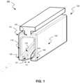
- Figure 1 shows a perspective view of a high-speed door sheet reintroduction device 100 according to an exemplary embodiment.
- the high-speed door sheet reintroduction device 100 is configured to reintroduce a high-speed door sheet which has come loose back into a high-speed door sheet guide.
- the high-speed door sheet reintroduction device 100 is intended for use with a high-speed door sheet. More specifically, the high-speed door sheet reintroduction device is intended to lie in line with a guide of the high-speed door sheet.
- Such a high-speed door sheet is configured to close and open an opening in the wall.
- the figure shows only a high-speed door sheet reintroduction device. The opening and the wall are not shown in the figure.
- a high-speed door comprises a high-speed door sheet which is movable between a closing position and an opening position, so that in the closing position the high-speed door sheet closes the opening in the wall and in the opening position the opening is at least partially open.
- a high-speed door sheet is typically manufactured from flexible material. In this way vehicles, for instance a forklift truck, can drive through the opening when the high-speed door sheet is in the opening position.
- the high-speed door sheet is provided to close, and typically consists of a cloth.
- the high-speed door sheet typically has two lateral edges. These two lateral edges are mountable in two respective high-speed door sheet guides which are mounted in the wall on either side of said opening.
- the two lateral edges are typically provided with a thickened seam which extends through the guides so that the freedom of movement of the wall is substantially exclusively upward and downward. Nevertheless, when the high-speed door sheet exits the high-speed door sheet guides, the high-speed door sheet reintroduction device 100 allows the high-speed door sheet which has come loose to be reintroduced back into the high-speed door sheet guide.
- the high-speed door sheet reintroduction device 100 is configured to lie in line with said high-speed door sheet guide.
- the high-speed door sheet reintroduction device 100 forms an extension of the high-speed door sheet guide, which is placed between the high-speed door sheet guide and an actuator.
- the high-speed door sheet reintroduction device 100 comprises an inlet 101, an outlet 102 and at least two legs 110, 130. In the mounted position the at least two legs 110 and 130 extend over a distance greater than the high-speed guides. The at least two legs thusextend beyond the high-speed guides. In this way the inlet 101 is easily accessible to a high-speed door which has come loose.
- the two legs 110, 130 further demarcate a slot extending between inlet 101 and outlet 102.
- the legs 110, 130 preferably extend from a base portion 150 of the high-speed door sheet reintroduction device 100. In this way the high-speed door sheet reintroduction device 100 is substantially U-shaped.
- the base portion 150 is configured to mount the high-speed door sheet reintroduction device movably on a frame of the biased high-speed door.
- Each of the two legs is provided at a distal end with a flange 120, 140.
- the first leg 110 comprises the first flange 120 and the second leg 120 the second flange 140.
- Said two flanges 120, 140 extend toward each other up to a predetermined distance A1, so that a groove is formed between the two flanges. This means that the flanges do not touch each other and that there is space between the outer ends of the flanges 120, 140. During reintroduction this space is partially taken up by the edge of the high-speed door sheet.
- Said two flanges 120, 140 have at the position of an outer end, the inlet 101 according to figure 1 and figure 2 , of the high-speed door sheet reintroduction device an edge portion 121, 141 having a surface which extends obliquely relative to a direction of movement of the high-speed door sheet so that the edge portions form a tapering inlet opening of the groove, wherein the distance between the surfaces 121, 141 of the two edge portions decreases as seen in the direction of movement.
- the direction of movement is illustrated in figures 1 and 2 by the arrow with reference symbol L. Because the distance between the surfaces 121, 141 of the two edge portions decreases, the groove forms a funnel.
- the funnel-like groove guides a movement of the lateral edges of the high-speed door sheet, the funnel-like groove particularly centring the lateral edges of the high-speed door sheet during upward movement. This allows for the lateral edges of the high-speed door sheet to be pulled into the guide in simple manner by the funnel-like groove when moving upward when the high-speed door sheet has been pushed out of or has exited the guides. In this way a high-speed door sheet reintroduction device 100 is provided which is simple and comprises a very small number of or even no moving parts.
- the flanges can each have at the position of an inlet segment 104 of the high-speed door sheet reintroduction device a second surface 122 which is directed toward the slot.
- the second surface is directed toward an inner side of the slot.
- the second surface 122 forms an angle ⁇ with the direction of movement of the high-speed door sheet, so that a cross-sectional area of the slot decreases, as seen in the direction of movement.
- the angle is preferably at least 20°, and a maximum of 60°. In this way the inlet opening of the high-speed door sheet reintroduction device is larger than the opening area of the further slot.
- the cross-sectional area further also decreases from the inlet to the further slot.
- An outlet segment 105 of the high-speed door sheet reintroduction device which outlet segment is located downstream of the inlet segment as seen in the direction of movement, can further have a substantially constant cross-sectional area.
- Figure 4 shows a side view of a section of the exemplary embodiment shown in figures 1 , 2 and 3 .
- the high-speed door sheet reintroduction device is illustrated in an assembled position wherein the high-speed door sheet reintroduction device 100 lies in line with a guide G of the high-speed door.
- the high-speed door sheet reintroduction device 100 and guide G are mounted in a substantially vertical direction.
- Figure 4 illustrates that the first leg 110 of the at least two legs extends to a position beyond the guide so that the inlet 101 of the high-speed door sheet reintroduction device is easily accessible to the high-speed door sheet.
- the insertion direction of the high-speed door sheet is illustrated with arrow L.
- FIG. 5 shows a top or bottom view of a section of a high-speed door with a high-speed door sheet reintroduction device.
- the high-speed door sheet reintroduction device 100 further comprises a tensioning means 160 which is configured to exert a predetermined tension on the high-speed door so that, when the high-speed door 180 is in the slot, the high-speed door sheet is tensioned. This allows the high-speed door to be tensioned and to be given a nicely finished and neat appearance. This however complicates things when the high-speed door sheet has come loose.
- the high-speed door sheet reintroduction device preferably further comprises a mounting profile 170 which is configured to be arranged between the base portion and the tensioning means.
- the mounting profile 170 has two coupling means, i.e. the first coupling means 171 and the second coupling means 172.
- the first coupling means is designed to couple the base portion to the mounting profile so that the high-speed door sheet reintroduction device can be mounted firmly on the mounting profile.
- the second coupling means 172 is designed to be mounted on the frame via the tensioning means so that the high-speed door sheet reintroduction device functions properly during use.
- the first coupling means can be designed in order to couple the base portion to the mounting profile. For instance by means of screwing, clamping or welding. In the shown situation the coupling means is a groove in which the base body can be arranged.
- the second coupling means can also be designed in different ways, such as by means of screws, bolts or clamps which fasten the tensioning means to the frame.
- the second coupling means can also be integrated in the tensioning means itself, whereby the tensioning means can be mounted directly on the frame.
- the tensioning means 160 further has a first outer end 161 and a second outer end 162, wherein the first outer end is coupled to the second coupling means and wherein the second outer end extends through the frame and comprises a stop, wherein the tensioning means further comprises a spring-mounted element which is arranged between the stop and the frame so that the spring-mounted element pushes against the frame and the stop in order to tensioning the high-speed door sheet reintroduction device.
Landscapes
- Engineering & Computer Science (AREA)
- Structural Engineering (AREA)
- Architecture (AREA)
- Civil Engineering (AREA)
- Operating, Guiding And Securing Of Roll- Type Closing Members (AREA)
Applications Claiming Priority (1)
| Application Number | Priority Date | Filing Date | Title |
|---|---|---|---|
| BE20235397A BE1031612B1 (nl) | 2023-05-12 | 2023-05-12 | Snelloopdeurbladherintroductieinrichting |
Publications (1)
| Publication Number | Publication Date |
|---|---|
| EP4461918A1 true EP4461918A1 (de) | 2024-11-13 |
Family
ID=86497423
Family Applications (1)
| Application Number | Title | Priority Date | Filing Date |
|---|---|---|---|
| EP24175457.1A Pending EP4461918A1 (de) | 2023-05-12 | 2024-05-13 | Wiedereinführsystem für hochgeschwindigkeitstürpaneel |
Country Status (2)
| Country | Link |
|---|---|
| EP (1) | EP4461918A1 (de) |
| BE (1) | BE1031612B1 (de) |
Citations (3)
| Publication number | Priority date | Publication date | Assignee | Title |
|---|---|---|---|---|
| US20050067118A1 (en) * | 2001-12-03 | 2005-03-31 | Benoit Coenrates | Shutter device with re-inserting element |
| US20060144530A1 (en) * | 2003-08-12 | 2006-07-06 | Toyohide Nagare | Sheet shutter |
| WO2006120655A2 (fr) * | 2005-05-13 | 2006-11-16 | Dynaco International S.A. | Chemin de guidage pour volet destine a la fermeture d'une baie ou autre ouverture |
-
2023
- 2023-05-12 BE BE20235397A patent/BE1031612B1/nl active IP Right Grant
-
2024
- 2024-05-13 EP EP24175457.1A patent/EP4461918A1/de active Pending
Patent Citations (4)
| Publication number | Priority date | Publication date | Assignee | Title |
|---|---|---|---|---|
| US20050067118A1 (en) * | 2001-12-03 | 2005-03-31 | Benoit Coenrates | Shutter device with re-inserting element |
| EP1454027B1 (de) | 2001-12-03 | 2016-04-20 | Entrematic Belgium Nv | Verschlussvorrichtung mit einer wiedereinführvorrichtung |
| US20060144530A1 (en) * | 2003-08-12 | 2006-07-06 | Toyohide Nagare | Sheet shutter |
| WO2006120655A2 (fr) * | 2005-05-13 | 2006-11-16 | Dynaco International S.A. | Chemin de guidage pour volet destine a la fermeture d'une baie ou autre ouverture |
Also Published As
| Publication number | Publication date |
|---|---|
| BE1031612B1 (nl) | 2024-12-11 |
| BE1031612A1 (nl) | 2024-12-06 |
Similar Documents
| Publication | Publication Date | Title |
|---|---|---|
| US8756866B2 (en) | Door glass clamp device | |
| JP5993593B2 (ja) | サンシェード装置 | |
| US9822568B2 (en) | Window regulator cable guide | |
| US8303028B2 (en) | Slide rail force distribution member | |
| JPWO2013062060A1 (ja) | ウインドレギュレータ | |
| WO2012114394A1 (en) | Step unit | |
| JP2009255724A (ja) | 車両用自動開閉装置 | |
| CN101678840B (zh) | 滑门 | |
| US6957850B2 (en) | Sunshade assembly for use in an open roof construction and open roof construction provided with such a sunshade assembly | |
| CN100531625C (zh) | 电动窗帘 | |
| KR101416359B1 (ko) | 선루프 글래스 부상 방지장치 및 이를 포함하는 선루프 조립체 | |
| EP1693246A3 (de) | Fahrzeugsitzschiene | |
| KR101809217B1 (ko) | 자동차용 도어 윈도우 레귤레이터의 캐리어 플레이트 | |
| CN207061571U (zh) | 电梯的导轨固定装置 | |
| BE1031612B1 (nl) | Snelloopdeurbladherintroductieinrichting | |
| JP5427098B2 (ja) | レール装置 | |
| KR20180132229A (ko) | 2단으로 현수막 거치가 가능한 난간 | |
| KR102433946B1 (ko) | 조립식 냉동·냉장고의 전동 자동화 미닫이 도어용 슬라이드 레일 프레임 | |
| KR20180032344A (ko) | 자동문의 안내 레일장치 | |
| JP2019214895A (ja) | 吊り下げ式ドアのドアガイド機構 | |
| KR101550405B1 (ko) | 방풍장치를 구비한 3중 연동 도어 | |
| KR200495064Y1 (ko) | 창문형 에어컨 지지장치 | |
| JP4368881B2 (ja) | 自動ドア装置のドア連結ベースセット | |
| JP2009062747A (ja) | スライド式ドアの樹脂製キャリッジレール、及びこれを備えるスライド式ドア | |
| CN210587727U (zh) | 一种激光切割机的推拉门 |
Legal Events
| Date | Code | Title | Description |
|---|---|---|---|
| PUAI | Public reference made under article 153(3) epc to a published international application that has entered the european phase |
Free format text: ORIGINAL CODE: 0009012 |
|
| STAA | Information on the status of an ep patent application or granted ep patent |
Free format text: STATUS: THE APPLICATION HAS BEEN PUBLISHED |
|
| AK | Designated contracting states |
Kind code of ref document: A1 Designated state(s): AL AT BE BG CH CY CZ DE DK EE ES FI FR GB GR HR HU IE IS IT LI LT LU LV MC ME MK MT NL NO PL PT RO RS SE SI SK SM TR |
|
| STAA | Information on the status of an ep patent application or granted ep patent |
Free format text: STATUS: REQUEST FOR EXAMINATION WAS MADE |
|
| 17P | Request for examination filed |
Effective date: 20250513 |
|
| STAA | Information on the status of an ep patent application or granted ep patent |
Free format text: STATUS: EXAMINATION IS IN PROGRESS |
|
| 17Q | First examination report despatched |
Effective date: 20250918 |