EP4461908B1 - Décodeur de clé à auto-ajustement - Google Patents
Décodeur de clé à auto-ajustement Download PDFInfo
- Publication number
- EP4461908B1 EP4461908B1 EP23189858.6A EP23189858A EP4461908B1 EP 4461908 B1 EP4461908 B1 EP 4461908B1 EP 23189858 A EP23189858 A EP 23189858A EP 4461908 B1 EP4461908 B1 EP 4461908B1
- Authority
- EP
- European Patent Office
- Prior art keywords
- carrier
- pumper
- channel
- hole
- guide bushing
- Prior art date
- Legal status (The legal status is an assumption and is not a legal conclusion. Google has not performed a legal analysis and makes no representation as to the accuracy of the status listed.)
- Active
Links
Images


Classifications
-
- E—FIXED CONSTRUCTIONS
- E05—LOCKS; KEYS; WINDOW OR DOOR FITTINGS; SAFES
- E05B—LOCKS; ACCESSORIES THEREFOR; HANDCUFFS
- E05B19/00—Keys; Accessories therefor
- E05B19/20—Skeleton keys; Devices for picking locks; Other devices for similar purposes ; Means to open locks not otherwise provided for, e.g. lock pullers
- E05B19/205—Lock decoders
Definitions
- the invention relates to a self-adjusting key decoder, comprising a handle and a working blade, which is used in the locksmithing industry, in particular for dimple cylinders.
- One example is a lock-opening and decoding tool kit, where three different types of tools from the kit are used in a specific sequence - first a spring-loaded detent is inserted, which pushes a stop plate to top position, simultaneously a spring-loaded compressor is inserted that presses the rest of the plates in sequence, which is a difficult process and requires time and precision. Then, the third tool is used, which is called decoding blade, which in combination with the spring detent is rotated 360° to unlock the lock.
- a major disadvantage of the decoding kit is the time it takes to perform the unlocking and subsequently decoding procedure.
- the complexity of the device leads to a low success rate, except in cases of very high technical training of the operator.
- a self-adjusting autolock decoder is known from utility model with registration number BG2371. It comprises an aluminum handle and a working body, and the handle is formed by arranged subsequently manipulator of a pumper, lifter handle and fixed handle. By means of a fastening element at the fixed handle, a fixed connection with a carrier, having holes, is provided by the operating body of the decoder.
- Transverse channels in which pins are installed with the possibility of reciprocating motion relative to the carrier in the direction transverse to the extension of the carrier, are provided in the front part of the carrier. Dowels, with the possibility of reciprocating motion relative to the pins in the direction transverse to the extension of the carrier, are located in channels of the pins.
- a pumper in the operating body, connected to the manipulator of a pumper by a thread for determining and regulating the revolution of the pumper by transforming a rotary motion of the manipulator of a pumper into a reciprocating motion of the pumper.
- Two lifters connected to the handle of the lifter are located in beds formed on both wide sides of the carrier, with the possibility of reciprocating motion.
- a disadvantage of this device is that it does not disclose a construction that can unlock dimple cylinders.
- the object of the invention is to provide a self-adjusting key decoder, with a handle and a working blade, which will be of increased precision, speed of unlocking and high efficiency in decoding dimple cylinders (also known as dimple locks and horizontal locks) which can be single-row, double-row, or triple-row cylinders, and which will be reliable for repeated use.
- decoding dimple cylinders also known as dimple locks and horizontal locks
- This object is achieved by creating a self-adjusting key decoder according to the present invention.
- this cylindrical channel 16 has a different diameter in different parts of its length, respectively it has a smaller diameter at its front end, so that the cylindrical part 6 of the manipulator of a pumper 3 is prevented from getting out of this narrowed end of the cylindrical channel 16.
- the cylindrical channel it is also possible for the cylindrical channel to have the same diameter along its entire length, and in order to prevent the cylindrical part 6 of the manipulator of a pumper 3 from getting out, another stopping element, for example circlip, washer or other suitable part is provided.
- another stopping element for example circlip, washer or other suitable part is provided.
- it is possible that such a stopping element is missing, and the prevention of outside exit of the manipulator of a pumper 3 from the cylindrical channel of the cylindrical part 6 is provided by the decoder assembly itself.
- the cylindrical channel 16 is located along the entire length of the fixed handle 1, and extends to a second side of the fixed handle 1.
- the fixed handle 1 also has at least one side hole 17 for stationary fixation to a working blade.
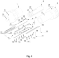
- the working blade for decoder comprises a carrier 4, which is an elongated element with a longitudinal channel 25 for working details, in which a lifter 9 and a pumper 7 are placed parallel to each other.
- the pumper 7 is mounted in the longitudinal channel 25 with the possibility for reciprocating motion relative to the carrier 4, in a direction parallel to the extension of the carrier 4. This motion provides a push on pins 13 so that the respective pins 13 can contact the respective teeth of the lock in order to decode it.
- the pumper 7 is, for example, a monolithically constructed element, comprising an elongated part, on one side of which, a protrusion with a shaped channel, a first gap, a first L-shaped part, a second gap, a second L-shaped part, and a free end of the elongated part of the pumper 7, which is not connected to another element, but rests on a spring 5, are formed subsequently.
- One arm of each L-shaped part is monolithically connected to the elongated part.
- the arms of the L-shaped parts, which are connected to the elongated part extend on one side above said elongated part.
- the free areas of the L-shaped parts of the pumper 7 come into contact with corresponding technological grooves of the carrier 4.
- the flat part of the carrier 4 as well as the pumper 7 have such channels, ribs and grooves that correspond and interact with their corresponding ribs, channels and grooves in the lock.
- Channels, ribs and grooves may also be provided on some of the elements of the decoder in order to provide assembly with other elements of the decoder, such as the pumper 7 with the carrier 4.
- the first L-shaped part and the first gap form a hook-shaped connection with carrying base 8.
- a guide bushing 2 with a cylindrical shape is placed, which has two bases on both sides of the cylinder.
- the carrier 4 comprises, arranged subsequently, cylindrical part and flat part, wherein a first through hole 18 in which the spring 5 is placed, a second through hole 19, a longitudinal linear hole 20 and a third hole 21 for connection by means of fastening elements 14 and first and second dowels 15, 32 to handle of decoder, are arranged subsequently laterally and longitudinally on the cylindrical part.
- the carrier 4 is immovably connected to the fixed handle 1 by means of a fastening element 14 in coaxially arranged third hole 21 of the carrier 4 and hole 30 of the fixed handle 1.
- Elongated sockets 31, which are parallel to each other, are located in the area of the flat part of the working blade, and they house under tension the pins 13, the pumper 7 is adapted to interact with the pins 13 to carry out coding, so that when carrying out the reciprocating motion of the pumper 7, it or an additional element mounted to it pushes the pins 13, which adjust themselves by touching the teeth of the lock to the correct combination for unlocking and locking.
- the number of sockets 31, respectively, pins 13, can vary, for example from four to eight sockets, respectively, four, five, six, seven, or eight sockets, in each one of which one pin 13 is located. Also, it is possible, for cylinders requiring two-row or three-row keys, the decoder to have the corresponding number of sockets on each side of the working blade.
- the pumper 7, with its second end, is connected by means of a hook-shaped connection to the carrying base 8, so that the carrying base 8 is located in the channel for working details 25 with the ability of performing the same reciprocating motion along the extension of the carrier 4 simultaneously with the pumper 7, wherein the lifter 9 and the pumper 7 contact each other in the channel 25 of the carrier 4.
- the pumper 7 and the carrying base 8 can be made as one monolithic element.
- a tip 11 with a tapered shape and a through hole for fixing to the carrier 4 are fixed to the channel for working details, at the free end of the flat part of the carrier, by means of a spring dowel 12, passing through a hole for spring 24.
- the carrying base 8 extends to the tip 11 at the extreme forward point of its reciprocating motion.
- the tip 11 is positioned to keep the pumper 7 and the carrying base 8 from falling out of the carrier 4, as well as it assists the feeding of the pins 13 into the cylinder.
- the tip 11 is designed having a tapered shape to provide a slope for easier contact with the plates of the cylinder.
- the tip 11 is fixed to the carrier 4.
- the carrying base 8 is, for example, a monolithically constructed element, comprising at one end a hook-shaped element for connecting to the pumper 7.
- a hook-shaped element for connecting to the pumper 7.
- the end socket is located at the free end of the carrying base 8, wherein the sockets 31 protrude on one side above the elongated part, on which side transverse channels are formed, extending from the end of each socket 31 to the opposite side of the elongated part, on which the sockets 31 are formed, to an outer edge extending longitudinally along a section of the elongated part of the carrying base 8, the outer edge forms a longitudinal channel interrupted by the said transverse channels.
- This construction is used to unlock some types of dimple cylinders, the profiles of which require such a construction of the sockets and transverse channels, and another construction of the carrying base 8 can be made for other embodiments.
- the carrying base 8 When the carrying base 8 is a separate element from the pumper 7, it can be a replaceable element of different construction, depending on the particular lock.
- the carrying base can have a different number of sockets 31 and pins 13 and/or sockets and pins of different shape and construction.
- the elongated sockets 31 are pyramidal in shape and the pins 13 are L-shaped, these shapes being exemplary, and other suitable shapes, for example triangular, can be used.
- the triangular shapes are suitable when the decoder is used for locks with only a bottom row of plates. If the locks have two rows of plates, top and bottom, respectively, it is preferable that the pins 13 are L-shaped to provide space to receive the top row of lock plates. It is possible that the pins are hinged, that is, articulated.
- the pins 13 are covered by the lifter 9, and in their uncovered position, when the lifter 9 is withdrawn, they contact the lock so that it is decoded.
- the self-adjusting key decoder before operation must be in closed or tightly retracted to the fixed handle 1 position of the manipulator of a pumper 3.
- the lifter 9 is in the front position and covers the carrying base 8 with the pins 13, and during insertion in and removal from the lock the lifter 9 prevents the pins 13 from moving from their initial fixed position.
- the decoder like an original key, makes contact with each plate, but unlike the key, the decoder of the invention does not have a channel of certain heights to engage the edges of the lock plates, so that it can be assumed that it stands in zero position compared to the positioning of the original keys.
Landscapes
- Structures Of Non-Positive Displacement Pumps (AREA)
- Press Drives And Press Lines (AREA)
Claims (3)
- Décodeur de clé auto-ajustable comprenant une poignée pour un décodeur et une lame de travail pour un décodeur, la poignée pour un décodeur comprenant un manipulateur de pompe (3) et une poignée fixe (1), une partie cylindrique (6) du manipulateur de pompe (3) étant disposée coaxialement et au moins partiellement dans un canal cylindrique (16) percé de deux trous opposés d'un premier côté de la poignée fixe (1), le canal cylindrique (16) s'étendant sur toute la longueur de la poignée fixe (1) et s'étendant jusqu'à un second côté de la poignée fixe (1), la poignée fixe (1) comportant au moins un trou latéral (17) pour une fixation fixe à la lame de travail, la lame de travail du décodeur comprenant un support (4), qui est un élément allongé doté d'un canal longitudinal (25) pour des détails de travail, dans lequel un élévateur (9) et une pompe (7) sont placés parallèlement l'un à l'autre, et sont montés de manière à pouvoir effectuer un mouvement alternatif par rapport au support (4) et par rapport à l'un et l'autre, dans une direction parallèle à l'extension du support (4), caractérisé en ce qu'une douille de guidage (2) de forme cylindrique est placée dans le canal cylindrique (16) de la partie cylindrique (6) du manipulateur de pompe (3), le manipulateur de pompe (3) et la douille de guidage (2) étant reliés entre eux, la douille de guidage présentant un canal (29) centré le long de son axe pour recevoir une lame de travail, au moins un canal linéaire (23) et au moins un canal en L (22) avec un côté court et un côté long étant formés sur la paroi périphérique de la douille de guidage (2) et disposés consécutivement le long de l'axe de la douille de guidage (2) pour se connecter consécutivement à la lame de travail, le canal linéaire au moins (23) étant disposé transversalement à la base de la douille de guidage (2), à un angle de sa base, le côté court du canal en L au moins (22) étant disposé parallèlement à l'axe de la douille de guidage (2), angulairement à sa base, et le côté long du canal en L (22) étant disposé parallèlement à l'axe de la douille de guidage (2), le support (4) comprenant consécutivement disposées une partie cylindrique et une partie plate, dans lequel un premier trou traversant (18) dans lequel un ressort (5) est placé, un deuxième trou traversant (19), un trou linéaire longitudinal (20) et un troisième trou (21) pour la connexion avec des éléments de fixation (14) et des première et deuxième chevilles (15, 32) à une poignée pour un décodeur étant situés consécutivement, latéralement et longitudinalement sur la partie cylindrique, le trou linéaire longitudinal (20) étant formé parallèlement à l'axe de la partie cylindrique du support (4), le canal longitudinal (25) pour les détails de travail étant formé sur la partie plate du support (4), et s'étendant également dans la partie cylindrique du support (4) et se connectant aux trous traversants (18, 19, 20) de la partie cylindrique, la pompe (7) étant située dans le canal longitudinal (25) avec la capacité de mouvement alternatif le long de l'extension du support (4) et ayant deux positions d'extrémité, respectivement une position d'extrémité arrière, où la pompe est rétractée au maximum dans le support (4) et est positionnée pour exercer une pression sur le ressort (5) avec une première extrémité, et une position d'extrémité avant où la pompe est poussée par le ressort (5) et s'étend au maximum vers l'avant, le dispositif de levage (9) étant un élément allongé, percé d'un trou (27) à une extrémité, par lequel il est fixé à l'aide de la seconde cheville (32) au trou linéaire longitudinal (20) du support (4), le manipulateur de pompe (3) et la douille de guidage (2) étant conçus et montés de manière à pouvoir effectuer deux types de mouvements par rapport au support (4), respectivement un mouvement alternatif longitudinalement à l'axe de la poignée et un mouvement rotatif, le mouvement alternatif étant réalisé par le mouvement de la première cheville (15) dans le côté long du canal en L au moins (22) de la douille de guidage (2), et le mouvement rotatif étant réalisé par le mouvement de la première cheville (15) dans le côté court du canal en L au moins (22) de la douille de guidage (2), simultanément au mouvement de la seconde cheville (32) dans le canal linéaire au moins (23), le support (4) de la lame de travail étant placé partiellement dans la douille de guidage (2), et étant fixée à celle-ci au moyen d'éléments de fixation avec une possibilité de transformer le mouvement rotatif du manipulateur de pompe (3) en mouvement alternatif de la pompe (7) par rapport au trou de la poignée fixe (1) et au support (4), le deuxième trou traversant (19) du support (4) et le canal en L au moins (22) de la douille de guidage (2) étant reliés par la première cheville (15) montée dans le canal en L au moins (22) et permettant un mouvement alternatif le long des côtés long et court du canal en L au moins (22), et le canal linéaire au moins (23) de la douille de guidage (2), le trou linéaire longitudinal (20) du support (4), une rainure intermédiaire (26) de la pompe (7) et le trou (27) du dispositif de levage (9) étant reliés par la deuxième cheville (32) montée mobile le long du trou linéaire longitudinal (20) du support (4) et le long du canal linéaire transversal (23) de la douille de guidage (2), le support (4) étant relié de manière inamovible à la poignée fixe (1) au moyen d'une fixation (14) dans un troisième trou coaxial (21) du support (4) et du trou (30) de la poignée fixe (1), au moins trois douilles allongées (31), parallèles entre elles, et logeant des broches (13) sous tension, étant disposées dans la région de la partie plate de la lame de travail, la pompe (7) étant configurée pour interagir avec les broches (13) pour effectuer un codage.
- Décodeur de clé auto-ajustable selon la revendication 1, caractérisé en ce que la pompe (7) est reliée par une seconde extrémité à une base porteuse (8), de sorte que cette dernière est située dans le canal (25) pour les détails de travail et est apte à effectuer le même mouvement alternatif le long du prolongement du support (4) simultanément avec la pompe (7), une pointe (11) étant fixée au canal pour les détails de travail, à l'extrémité libre de la partie plate du support, au moyen d'un élément de fixation (12) sur lequel la base porteuse (8) s'étend au point final de son mouvement alternatif, au moins trois douilles allongées (31) parallèles entre elles, qui logent les broches (13) sous tension, étant disposées sur la base porteuse (8) transversalement et en angle par rapport au prolongement de la base porteuse (8), les douilles (31) faisant saillie d'un côté au-dessus de la base porteuse (8).
- Décodeur de clé auto-ajustable selon la revendication 2, caractérisé en ce que des rainures technologiques sont formées sur la partie plate du support (4).
Applications Claiming Priority (1)
| Application Number | Priority Date | Filing Date | Title |
|---|---|---|---|
| EP23472002 | 2023-05-12 |
Publications (3)
| Publication Number | Publication Date |
|---|---|
| EP4461908A1 EP4461908A1 (fr) | 2024-11-13 |
| EP4461908B1 true EP4461908B1 (fr) | 2025-06-25 |
| EP4461908C0 EP4461908C0 (fr) | 2025-06-25 |
Family
ID=87933531
Family Applications (1)
| Application Number | Title | Priority Date | Filing Date |
|---|---|---|---|
| EP23189858.6A Active EP4461908B1 (fr) | 2023-05-12 | 2023-08-04 | Décodeur de clé à auto-ajustement |
Country Status (2)
| Country | Link |
|---|---|
| EP (1) | EP4461908B1 (fr) |
| BG (1) | BG4657U1 (fr) |
Family Cites Families (3)
| Publication number | Priority date | Publication date | Assignee | Title |
|---|---|---|---|---|
| BG112204A (bg) * | 2016-01-28 | 2017-08-31 | Димитър Ивайлов | Команден блок и система за дистан ционно чрез мобилна комуникацион на мрежа и радиочестотен канал, деб локиране достъпа в обособена зона (71) |
| BG2371U1 (bg) * | 2016-01-28 | 2016-12-30 | Димитър Ивайлов | Самонагаждащо се автоключарско декодиращо устройство |
| ES2942425T3 (es) * | 2018-11-06 | 2023-06-01 | Georgi Angelov Ivaylov | Herramienta de cerrajería profesional |
-
2023
- 2023-08-04 EP EP23189858.6A patent/EP4461908B1/fr active Active
- 2023-08-09 BG BG5810U patent/BG4657U1/bg unknown
Also Published As
| Publication number | Publication date |
|---|---|
| BG4657U1 (bg) | 2024-01-15 |
| EP4461908C0 (fr) | 2025-06-25 |
| EP4461908A1 (fr) | 2024-11-13 |
Similar Documents
| Publication | Publication Date | Title |
|---|---|---|
| US7370502B2 (en) | High security lock and key blade combination | |
| US6871520B2 (en) | Devices, methods, and systems for rekeying a lock assembly | |
| US8291735B1 (en) | Rekeyable lock cylinder having rotatable key followers | |
| US8347678B2 (en) | Rekeyable lock cylinder assembly | |
| US6862909B2 (en) | Devices, methods, and systems for keying a lock assembly | |
| US7634931B2 (en) | Rekeyable lock cylinder assembly with adjustable pin lengths | |
| USRE45627E1 (en) | Re-keyable lock cylinder | |
| US10087654B2 (en) | Cylinder lock | |
| HU215744B (hu) | Hengerzár, zárótest, reteszelőléc, valamint hengerzár és kulcs kombináció | |
| EP0110647B1 (fr) | Serrures cylindriques | |
| US7712344B2 (en) | Key-changeable lock | |
| EP4461908B1 (fr) | Décodeur de clé à auto-ajustement | |
| HU215769B (hu) | Hengerzár és egy hozzá tartozó laposkulcs | |
| BG4498U1 (bg) | Автоматичен ключарски инструмент | |
| KR200271747Y1 (ko) | 자물쇠 뭉치의 회전로드 | |
| US20200399931A1 (en) | Lock | |
| BG114135A (bg) | Ключарски инструмент | |
| JPH0540550U (ja) | シリンダー錠 |
Legal Events
| Date | Code | Title | Description |
|---|---|---|---|
| PUAI | Public reference made under article 153(3) epc to a published international application that has entered the european phase |
Free format text: ORIGINAL CODE: 0009012 |
|
| STAA | Information on the status of an ep patent application or granted ep patent |
Free format text: STATUS: THE APPLICATION HAS BEEN PUBLISHED |
|
| AK | Designated contracting states |
Kind code of ref document: A1 Designated state(s): AL AT BE BG CH CY CZ DE DK EE ES FI FR GB GR HR HU IE IS IT LI LT LU LV MC ME MK MT NL NO PL PT RO RS SE SI SK SM TR |
|
| STAA | Information on the status of an ep patent application or granted ep patent |
Free format text: STATUS: REQUEST FOR EXAMINATION WAS MADE |
|
| 17P | Request for examination filed |
Effective date: 20241125 |
|
| RBV | Designated contracting states (corrected) |
Designated state(s): AL AT BE BG CH CY CZ DE DK EE ES FI FR GB GR HR HU IE IS IT LI LT LU LV MC ME MK MT NL NO PL PT RO RS SE SI SK SM TR |
|
| GRAP | Despatch of communication of intention to grant a patent |
Free format text: ORIGINAL CODE: EPIDOSNIGR1 |
|
| STAA | Information on the status of an ep patent application or granted ep patent |
Free format text: STATUS: GRANT OF PATENT IS INTENDED |
|
| RIC1 | Information provided on ipc code assigned before grant |
Ipc: E05B 19/20 20060101AFI20250116BHEP |
|
| INTG | Intention to grant announced |
Effective date: 20250130 |
|
| GRAS | Grant fee paid |
Free format text: ORIGINAL CODE: EPIDOSNIGR3 |
|
| GRAA | (expected) grant |
Free format text: ORIGINAL CODE: 0009210 |
|
| STAA | Information on the status of an ep patent application or granted ep patent |
Free format text: STATUS: THE PATENT HAS BEEN GRANTED |
|
| AK | Designated contracting states |
Kind code of ref document: B1 Designated state(s): AL AT BE BG CH CY CZ DE DK EE ES FI FR GB GR HR HU IE IS IT LI LT LU LV MC ME MK MT NL NO PL PT RO RS SE SI SK SM TR |
|
| REG | Reference to a national code |
Ref country code: GB Ref legal event code: FG4D |
|
| REG | Reference to a national code |
Ref country code: CH Ref legal event code: EP |
|
| REG | Reference to a national code |
Ref country code: CH Ref legal event code: EP |
|
| REG | Reference to a national code |
Ref country code: IE Ref legal event code: FG4D |
|
| REG | Reference to a national code |
Ref country code: DE Ref legal event code: R096 Ref document number: 602023004248 Country of ref document: DE |
|
| U01 | Request for unitary effect filed |
Effective date: 20250709 |
|
| U07 | Unitary effect registered |
Designated state(s): AT BE BG DE DK EE FI FR IT LT LU LV MT NL PT RO SE SI Effective date: 20250715 |
|
| U20 | Renewal fee for the european patent with unitary effect paid |
Year of fee payment: 3 Effective date: 20250820 |
|
| PG25 | Lapsed in a contracting state [announced via postgrant information from national office to epo] |
Ref country code: GR Free format text: LAPSE BECAUSE OF FAILURE TO SUBMIT A TRANSLATION OF THE DESCRIPTION OR TO PAY THE FEE WITHIN THE PRESCRIBED TIME-LIMIT Effective date: 20250926 Ref country code: NO Free format text: LAPSE BECAUSE OF FAILURE TO SUBMIT A TRANSLATION OF THE DESCRIPTION OR TO PAY THE FEE WITHIN THE PRESCRIBED TIME-LIMIT Effective date: 20250925 |
|
| PG25 | Lapsed in a contracting state [announced via postgrant information from national office to epo] |
Ref country code: HR Free format text: LAPSE BECAUSE OF FAILURE TO SUBMIT A TRANSLATION OF THE DESCRIPTION OR TO PAY THE FEE WITHIN THE PRESCRIBED TIME-LIMIT Effective date: 20250625 |
|
| PG25 | Lapsed in a contracting state [announced via postgrant information from national office to epo] |
Ref country code: RS Free format text: LAPSE BECAUSE OF FAILURE TO SUBMIT A TRANSLATION OF THE DESCRIPTION OR TO PAY THE FEE WITHIN THE PRESCRIBED TIME-LIMIT Effective date: 20250925 |
|
| PG25 | Lapsed in a contracting state [announced via postgrant information from national office to epo] |
Ref country code: IS Free format text: LAPSE BECAUSE OF FAILURE TO SUBMIT A TRANSLATION OF THE DESCRIPTION OR TO PAY THE FEE WITHIN THE PRESCRIBED TIME-LIMIT Effective date: 20251025 |
|
| PG25 | Lapsed in a contracting state [announced via postgrant information from national office to epo] |
Ref country code: SM Free format text: LAPSE BECAUSE OF FAILURE TO SUBMIT A TRANSLATION OF THE DESCRIPTION OR TO PAY THE FEE WITHIN THE PRESCRIBED TIME-LIMIT Effective date: 20250625 |
|
| PG25 | Lapsed in a contracting state [announced via postgrant information from national office to epo] |
Ref country code: CZ Free format text: LAPSE BECAUSE OF FAILURE TO SUBMIT A TRANSLATION OF THE DESCRIPTION OR TO PAY THE FEE WITHIN THE PRESCRIBED TIME-LIMIT Effective date: 20250625 |
|
| PG25 | Lapsed in a contracting state [announced via postgrant information from national office to epo] |
Ref country code: PL Free format text: LAPSE BECAUSE OF FAILURE TO SUBMIT A TRANSLATION OF THE DESCRIPTION OR TO PAY THE FEE WITHIN THE PRESCRIBED TIME-LIMIT Effective date: 20250625 |
|
| PG25 | Lapsed in a contracting state [announced via postgrant information from national office to epo] |
Ref country code: SK Free format text: LAPSE BECAUSE OF FAILURE TO SUBMIT A TRANSLATION OF THE DESCRIPTION OR TO PAY THE FEE WITHIN THE PRESCRIBED TIME-LIMIT Effective date: 20250625 |
|
| PG25 | Lapsed in a contracting state [announced via postgrant information from national office to epo] |
Ref country code: ES Free format text: LAPSE BECAUSE OF FAILURE TO SUBMIT A TRANSLATION OF THE DESCRIPTION OR TO PAY THE FEE WITHIN THE PRESCRIBED TIME-LIMIT Effective date: 20250625 |