EP4461908A1 - Décodeur de clé à auto-ajustement - Google Patents
Décodeur de clé à auto-ajustement Download PDFInfo
- Publication number
- EP4461908A1 EP4461908A1 EP23189858.6A EP23189858A EP4461908A1 EP 4461908 A1 EP4461908 A1 EP 4461908A1 EP 23189858 A EP23189858 A EP 23189858A EP 4461908 A1 EP4461908 A1 EP 4461908A1
- Authority
- EP
- European Patent Office
- Prior art keywords
- carrier
- pumper
- channel
- hole
- guide bushing
- Prior art date
- Legal status (The legal status is an assumption and is not a legal conclusion. Google has not performed a legal analysis and makes no representation as to the accuracy of the status listed.)
- Granted
Links
Images


Classifications
-
- E—FIXED CONSTRUCTIONS
- E05—LOCKS; KEYS; WINDOW OR DOOR FITTINGS; SAFES
- E05B—LOCKS; ACCESSORIES THEREFOR; HANDCUFFS
- E05B19/00—Keys; Accessories therefor
- E05B19/20—Skeleton keys; Devices for picking locks; Other devices for similar purposes ; Means to open locks not otherwise provided for, e.g. lock pullers
- E05B19/205—Lock decoders
Definitions
- the invention relates to a self-adjusting key decoder, comprising a handle and a working blade, which is used in the locksmithing industry, in particular for dimple cylinders.
- One example is a lock-opening and decoding tool kit, where three different types of tools from the kit are used in a specific sequence - first a spring-loaded detent is inserted, which pushes a stop plate to top position, simultaneously a spring-loaded compressor is inserted that presses the rest of the plates in sequence, which is a difficult process and requires time and precision. Then, the third tool is used, which is called decoding blade, which in combination with the spring detent is rotated 360° to unlock the lock.
- a major disadvantage of the decoding kit is the time it takes to perform the unlocking and subsequently decoding procedure.
- the complexity of the device leads to a low success rate, except in cases of very high technical training of the operator.
- a self-adjusting autolock decoder is known from utility model with registration number BG2371. It comprises an aluminum handle and a working body, and the handle is formed by arranged subsequently manipulator of a pumper, lifter handle and fixed handle. By means of a fastening element at the fixed handle, a fixed connection with a carrier, having holes, is provided by the operating body of the decoder.
- Transverse channels in which pins are installed with the possibility of reciprocating motion relative to the carrier in the direction transverse to the extension of the carrier, are provided in the front part of the carrier. Dowels, with the possibility of reciprocating motion relative to the pins in the direction transverse to the extension of the carrier, are located in channels of the pins.
- a pumper in the operating body, connected to the manipulator of a pumper by a thread for determining and regulating the revolution of the pumper by transforming a rotary motion of the manipulator of a pumper into a reciprocating motion of the pumper.
- Two lifters connected to the handle of the lifter are located in beds formed on both wide sides of the carrier, with the possibility of reciprocating motion.
- a disadvantage of this device is that it does not disclose a construction that can unlock dimple cylinders.
- the object of the invention is to provide a self-adjusting key decoder, with a handle and a working blade, which will be of increased precision, speed of unlocking and high efficiency in decoding dimple cylinders (also known as dimple locks and horizontal locks) which can be single-row, double-row, or triple-row cylinders, and which will be reliable for repeated use.
- decoding dimple cylinders also known as dimple locks and horizontal locks
- This object is achieved by creating a self-adjusting key decoder according to the present invention.
- the self-adjusting key decoder comprises a handle for the decoder and a working blade for the decoder.
- the handle for the decoder comprises a manipulator of a pumper and a fixed handle, wherein a cylindrical portion of the manipulator of a pumper is located coaxially and at least partially in a cylindrical channel with two opposite holes, on a first side of the fixed handle. This cylindrical channel is located along the entire length of the fixed handle, and extends to a second side of the fixed handle, wherein the fixed handle has at least one side hole for fixed attachment to the working blade.
- the working blade for decoder comprises a carrier, which is an elongated element with a longitudinal channel for working details, in which a lifter and a pumper are placed parallel to each other, which are mounted with the possibility for reciprocating motion relative to the carrier, in a direction parallel to the extension of the carrier.
- a cylindrical guide bushing is placed in the cylindrical channel of the cylindrical part of the manipulator of a pumper. The manipulator of a pumper and the guide bushing are connected to each other.
- the guide bushing has a channel located centrally along its axis to receive a working blade.
- At least one linear channel and at least one L-shaped channel with a short side and a long side for connection with the working blade are formed on the surrounding wall of the guide bushing, arranged subsequently along the axis of the guide bushing.
- the at least one linear channel is located transversely to the axis of the guide bushing, at an angle to its base, wherein the short side of the at least one L-shaped channel is located parallel to the base of the guide bushing and the long side of the L-shaped channel is located parallel to the axis of the guide bushing.
- the carrier comprises, arranged subsequently, cylindrical part and flat part, wherein, a first through hole in which a spring is placed, a second through hole, a longitudinal linear hole and a third hole for connection by means of fastening elements and dowels to handle of decoder, are arranged subsequently, laterally and longitudinally to the cylindrical part, the longitudinal linear hole is formed parallel to the axis of the cylindrical part of the carrier.
- the longitudinal channel for working details is formed on the flat part of the carrier, and also extends into the cylindrical part of the carrier and connects with the through holes of the cylindrical part.
- the pumper is located in the longitudinal channel with the possibility for reciprocating motion along the extension of the carrier and has two end positions, rear end position, where the pumper is maximally retracted into the carrier and is positioned to exert pressure on the spring with first end, and front end position where the pumper is pushed by the spring and extends maximally forward.
- the lifter is an elongated element with a hole at one end, by which it is fixed with a dowel to the longitudinal linear hole of the carrier.
- the manipulator of a pumper with the guide bushing are designed and mounted with the ability to perform two types of motions relative to the carrier, respectively reciprocating motion longitudinally to the axis of the handle and rotary motion, wherein the reciprocating motion is carried out by the motion of the first dowel in the long side of the at least one L-shaped channel of the guide bushing, and the rotary motion is performed by motion of the first dowel in the short side of the at least one L-shaped channel of the guide bushing, simultaneously with motion of the second dowel in the at least one linear channel of the guide bushing.
- the carrier of the working blade is placed partially in the guide bushing, and is fixed to it by means of fasteners capable of transforming the rotary motion of the manipulator of a pumper into a reciprocating motion of the pumper relative to the hole of the fixed handle and the carrier, respectively, the second through hole of the carrier and the at least one L-shaped channel of the guide bushing are connected by the first dowel mounted in the at least one L-shaped channel with the ability for reciprocating motion both along the long side and along the short side of the at least one L-shaped channel.
- the at least one linear channel of the guide bushing, the carrier's longitudinal linear hole, intermediate groove of the pumper, and the hole of the lifter are connected by the second dowel mounted with the possibility to move along both the carrier's longitudinal linear hole and the transverse linear channel of the guide bushing.
- the carrier is immovably connected to the fixed handle by means of a fastener in a coaxially located third hole of the carrier and a hole of the fixed handle.
- At least three elongate sockets, which are parallel to each other, and which house pins under tension, are arranged in the region of the flat part of the working blade, the pumper being adapted to interact with the pins to carry out encoding.
- a second end of the pumper is connected to a carrying base, so that the carrying base is located in the channel for working details with the ability to perform the same reciprocating motion along the extension of the carrier simultaneously with the pumper.
- a tip is fixed to the channel for working details, at the free end of the flat part of the carrier, by means of a fastening element, to which the carrying base extends at the end point of its reciprocating motion.
- the at least three elongated sockets parallel to each other, which house the pins under tension, are arranged on the carrying base transversely and at an angle to the extension of the carrying base, wherein the sockets protrude on one side above the carrying base.
- technological grooves are formed on the flat part of the carrier, which serve to accommodate various parts of the self-adjusting key decoder, or to provide connection between such parts, or facilitate the insertion of the decoder into the corresponding lock, on which it will be used.
- the device according to the invention allows the operator to open and decode dimple cylinders with great speed, without the need for technical preparation and/or the use of complex locksmith techniques or kits that would slow down the opening process or lead to additional technical difficulties such as destroying the lock, door, window, safe, or other part near the lock.
- Unlocking and locking by means of the device according to the invention can be done unlimited number of times without having to dismantle the lock.
- the unlocking speed allows the decoder to be used for emergency non-destructive unlocking as well.
- the decoder can decode the lock, which has plates, each contacting the pins.
- One of the great advantages of the invention is that it can determine and "adjust" to the different height of each of the plates totally automatically.
- the operator can read the code, determining with great accuracy the depth of the plates, and in this way, it is easy to make a duplicate key with a very high degree of precision, unlike other locksmith emergency opening methods in the absence of an original key.
- the self-adjusting key decoder allows decoding of various types of dimple cylinders, and if necessary, the decoder can be disassembled and the working blade in the handle can be replaced with a suitable one.
- the self-adjusting key decoder acts as a universal key for dimple cylinders.
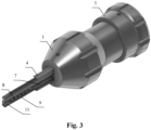
- the self-adjusting key decoder of the invention comprises a handle and a working blade that interact with each other to carry out the decoding process.
- the handle of the decoder comprises a manipulator of a pumper 3 and a fixed handle 1, wherein a cylindrical part 6 of the manipulator of a pumper 3 is located coaxially in a cylindrical channel 16 with two opposite holes, on first side of the fixed handle 1.
- this cylindrical channel 16 has a different diameter in different parts of its length, respectively it has a smaller diameter at its front end, so that the cylindrical part 6 of the manipulator of a pumper 3 is prevented from getting out of this narrowed end of the cylindrical channel 16.
- the cylindrical channel it is also possible for the cylindrical channel to have the same diameter along its entire length, and in order to prevent the cylindrical part 6 of the manipulator of a pumper 3 from getting out, another stopping element, for example circlip, washer or other suitable part is provided.
- another stopping element for example circlip, washer or other suitable part is provided.
- it is possible that such a stopping element is missing, and the prevention of outside exit of the manipulator of a pumper 3 from the cylindrical channel of the cylindrical part 6 is provided by the decoder assembly itself.
- the cylindrical channel 16 is located along the entire length of the fixed handle 1, and extends to a second side of the fixed handle 1.
- the fixed handle 1 also has at least one side hole 17 for stationary fixation to a working blade.
- the working blade for decoder comprises a carrier 4, which is an elongated element with a longitudinal channel 25 for working details, in which a lifter 9 and a pumper 7 are placed parallel to each other.
- the pumper 7 is mounted in the longitudinal channel 25 with the possibility for reciprocating motion relative to the carrier 4, in a direction parallel to the extension of the carrier 4. This motion provides a push on pins 13 so that the respective pins 13 can contact the respective teeth of the lock in order to decode it.
- the pumper 7 is, for example, a monolithically constructed element, comprising an elongated part, on one side of which, a protrusion with a shaped channel, a first gap, a first L-shaped part, a second gap, a second L-shaped part, and a free end of the elongated part of the pumper 7, which is not connected to another element, but rests on a spring 5, are formed subsequently.
- One arm of each L-shaped part is monolithically connected to the elongated part.
- the arms of the L-shaped parts, which are connected to the elongated part extend on one side above said elongated part.
- the free areas of the L-shaped parts of the pumper 7 come into contact with corresponding technological grooves of the carrier 4.
- the flat part of the carrier 4 as well as the pumper 7 have such channels, ribs and grooves that correspond and interact with their corresponding ribs, channels and grooves in the lock.
- Channels, ribs and grooves may also be provided on some of the elements of the decoder in order to provide assembly with other elements of the decoder, such as the pumper 7 with the carrier 4.
- the first L-shaped part and the first gap form a hook-shaped connection with carrying base 8.
- a guide bushing 2 with a cylindrical shape is placed, which has two bases on both sides of the cylinder.
- the manipulator of a pumper 3 and the guide bushing 2 are connected to each other by means of a fastening element 14 through coaxial side holes 28 provided on each of the two elements, or alternatively by a geometric fit or in another suitable manner.
- the guide bushing has a channel 29 located centrally along its axis for receiving a working blade.
- two opposite linear channels 23 and two opposite L-shaped channels 22 with a short and a long side are formed on the surrounding wall of the guide bushing 2 for connection with working blade.
- the guide bushing 2 it is possible for the guide bushing 2 to have only one linear channel 23 and one L-shaped channel 22.
- the linear channels 23 and the L-shaped channels 22 are arranged subsequently along the axis of the guide bushing 2, so that the linear channels 23 and the short sides of the L-shaped channels 22 are adjacent to each other.
- the linear channels 23 are located transversely to the axis of the guide bushing 2, at an angle to its base, thus forming a slight slope towards this base.
- the short side of the L-shaped channels 22 is located parallel to the base of the guide bushing 2, and the long side of the L-shaped channels 22 is located parallel to the axis of the guide bushing 2.
- the purpose of this arrangement of the channels is to ensure an uneven distance between the short sides of the L-shaped channels 22 and the linear channels 23, for example, the distance is half a millimeter shorter at one end of the linear channels 23, provided that the linear channels 23 and the short sides of the L-shaped channels 22 are of equal length so that the longitudinal axes of the linear channels 23 and the short sides of the L-shaped channels 22 form an acute angle.
- the lengths of the channels can be different, in which case the distance between the linear channels 23 and the short side of the L-shaped channels 22 will be different, and thus the slope (the angle between them) will be different. The greater this slope is, the greater the stroke of the reciprocating motion of the pumper 7 is.
- the carrier 4 comprises, arranged subsequently, cylindrical part and flat part, wherein a first through hole 18 in which the spring 5 is placed, a second through hole 19, a longitudinal linear hole 20 and a third hole 21 for connection by means of fastening elements 14 and first and second dowels 15, 32 to handle of decoder, are arranged subsequently laterally and longitudinally on the cylindrical part.
- the first through hole 18 in one embodiment has a square cross-section, thus forming a cube-shaped socket for the spring.
- other shapes of the first through hole 18 can be used, for example, circle, rectangle or another.
- the carrier 4 may have different profiles relative to the respective lock it will decode, for example, as shown in the figures, the flat part of the carrier 4 may have two narrow sides and two wide sides, the narrow sides being located in the plane of the holes 18, 19, 20, 21 of the cylindrical part.
- the narrow sides of the flat part of the carrier 4 are cut in two planes of different heights, the part on the side of the free end of the narrow sides of the flat part of the carrier 4 is in a lower plane than the part on the side of the narrow sides of the flat part of the carrier 4, which connects to the cylindrical part of the carrier 4.
- the longitudinal channel 25 Two technological grooves, the longitudinal channel 25, and another end technological groove are arranged subsequently longitudinally on one wide side of the flat part of the carrier 4, the longitudinal channel 25 also extends into the cylindrical part of the carrier 4 and communicates with the through holes 18, 19, 20, and optionally the hole 21, of the cylindrical part.
- the spring 5 may be, for example, an elastic plate, which is M-shaped in cross-section, but alternatively other types of suitable springs known from the state of the art may be used.
- the longitudinal linear hole 20 is formed parallel to the axis of the cylindrical part of the carrier 4.
- the pumper 7 is located in the longitudinal channel 25 with the possibility for reciprocating motion along the extension of the carrier 4 and has two end positions, respectively rear end position, in which the pumper is maximally retracted into the carrier 4 and is positioned to exert pressure on the spring 5 with first end, and front end position where the pumper is pushed by the spring 5 and extends maximally forward.
- the lifter 9 is an elongated element with a hole 27 at one end, by which it is fixed with a second dowel 32 to the longitudinal linear hole 20 of the carrier 4.
- the lifter 9 serves to cover the pins 13 when it is in front end position so that they cannot interact with the lock when necessary, and accordingly, to uncover the pins 13 when it is in rear end position so that they can interact with the lock when necessary, and perform the necessary decoding.
- the decoder can be easily inserted in and removed from the lock.
- the lifter 9 is of S-shaped cross-section, having the shape of two parallel sides connected by an intermediate side, the two parallel sides extending in opposite directions to each other relative to the intermediate side, lateral to the intermediate side there is a projecting edge extending the entire length of the lifter 9, at one end in a longitudinal direction the lifter 9 is beveled to contact the teeth of the lock, one of its two parallel sides is thus shorter than the other, on the side of the shorter of the two parallel sides, at the opposite end of the lifter in longitudinal direction, is formed a hole 27 for fixing by the second dowel 32.
- Other constructions of the lifter 9 are also possible, as long as its reciprocating motion is ensured, which uncovers and covers the pins 13 as needed when working with the decoder.
- the manipulator of a pumper 3 with the guide bushing 2 are designed and mounted with the possibility of performing two types of motions relative to the carrier 4, respectively, a reciprocating motion longitudinally to the axis of the handle and a rotary motion, wherein the reciprocating motion is carried out by moving the first dowel 15 in the long side of the L-shaped channels 22 of the guide bushing 2, and the rotary motion is carried out by moving the first dowel 15 in the short side of the L-shaped channels 22 of the guide bushing 2, simultaneously with the movement of the second dowel 32 in the linear channels 23.
- the carrier 4 of the working blade is placed partially in the guide bushing 2, and is fixed to it by means of fasteners capable of transforming a rotary motion of the manipulator of a pumper 3 into a reciprocating motion of the pumper 7 with respect to the hole of the fixed handle 1 and the carrier 4, respectively, the second through hole 19 of the carrier 4 and the L-shaped channels 22 of the guide bushing 2 are connected by the first dowel 15 mounted in the L-shaped channels 22 with the ability for reciprocating motion both along the long and along the short side of the L-shaped channels 22.
- the linear channels 23 of the guide bushing 2, the longitudinal linear hole 20 of the carrier 4, the intermediate groove 26 of the pumper 7, and the hole 27 of the lifter 9 are connected by the second dowel 32, mounted to be able to move along both the longitudinal linear hole 20 of the carrier 4, as well as along the transverse linear channel 23 of the guide bushing 2.
- the carrier 4 is immovably connected to the fixed handle 1 by means of a fastening element 14 in coaxially arranged third hole 21 of the carrier 4 and hole 30 of the fixed handle 1.
- Elongated sockets 31, which are parallel to each other, are located in the area of the flat part of the working blade, and they house under tension the pins 13, the pumper 7 is adapted to interact with the pins 13 to carry out coding, so that when carrying out the reciprocating motion of the pumper 7, it or an additional element mounted to it pushes the pins 13, which adjust themselves by touching the teeth of the lock to the correct combination for unlocking and locking.
- the number of sockets 31, respectively, pins 13, can vary, for example from four to eight sockets, respectively, four, five, six, seven, or eight sockets, in each one of which one pin 13 is located. Also, it is possible, for cylinders requiring two-row or three-row keys, the decoder to have the corresponding number of sockets on each side of the working blade.
- the pumper 7, with its second end, is connected by means of a hook-shaped connection to the carrying base 8, so that the carrying base 8 is located in the channel for working details 25 with the ability of performing the same reciprocating motion along the extension of the carrier 4 simultaneously with the pumper 7, wherein the lifter 9 and the pumper 7 contact each other in the channel 25 of the carrier 4.
- the pumper 7 and the carrying base 8 can be made as one monolithic element.
- a tip 11 with a tapered shape and a through hole for fixing to the carrier 4 are fixed to the channel for working details, at the free end of the flat part of the carrier, by means of a spring dowel 12, passing through a hole for spring 24.
- the carrying base 8 extends to the tip 11 at the extreme forward point of its reciprocating motion.
- the tip 11 is positioned to keep the pumper 7 and the carrying base 8 from falling out of the carrier 4, as well as it assists the feeding of the pins 13 into the cylinder.
- the tip 11 is designed having a tapered shape to provide a slope for easier contact with the plates of the cylinder.
- the tip 11 is fixed to the carrier 4.
- An exemplary variant of fixing is to place the said spring dowel under the tip to serve as a piston at the front of the decoder.
- This dowel is mounted under tension so that it does not fall out of the tip 11 and the carrier 4.
- the carrying base 8 is, for example, a monolithically constructed element, comprising at one end a hook-shaped element for connecting to the pumper 7.
- a hook-shaped element for connecting to the pumper 7.
- the end socket is located at the free end of the carrying base 8, wherein the sockets 31 protrude on one side above the elongated part, on which side transverse channels are formed, extending from the end of each socket 31 to the opposite side of the elongated part, on which the sockets 31 are formed, to an outer edge extending longitudinally along a section of the elongated part of the carrying base 8, the outer edge forms a longitudinal channel interrupted by the said transverse channels.
- This construction is used to unlock some types of dimple cylinders, the profiles of which require such a construction of the sockets and transverse channels, and another construction of the carrying base 8 can be made for other embodiments.
- the carrying base 8 When the carrying base 8 is a separate element from the pumper 7, it can be a replaceable element of different construction, depending on the particular lock.
- the carrying base can have a different number of sockets 31 and pins 13 and/or sockets and pins of different shape and construction.
- the elongated sockets 31 are pyramidal in shape and the pins 13 are L-shaped, these shapes being exemplary, and other suitable shapes, for example triangular, can be used.
- the triangular shapes are suitable when the decoder is used for locks with only a bottom row of plates. If the locks have two rows of plates, top and bottom, respectively, it is preferable that the pins 13 are L-shaped to provide space to receive the top row of lock plates. It is possible that the pins are hinged, that is, articulated.
- the pins 13 are covered by the lifter 9, and in their uncovered position, when the lifter 9 is withdrawn, they contact the lock so that it is decoded.
- the flat part of the carrier 4 can have technological grooves, which have an auxiliary function, and may serve different purposes, for example, they may receive parts of the decoder, they may serve to establish a connection between parts of the decoder, or they can be created by a cutting tool in order to more easily shape the geometry of the working blade, or they can provide the necessary geometry of the working blade so that it is easily inserted into the corresponding dimple cylinder in order to decode it.
- the technological grooves can be shaped in different ways, for example by electrical discharge machine.
- a channel 33 for a sealing plate 10 is formed longitudinally along the entire cylindrical part of the carrier 4, which channel 33 is formed at the end of the surrounding surface of the cylindrical part of the carrier 4, thus forming a longitudinal slot of the cylindrical part of the carrier 4.
- the sealing plate 10 serves to close the technological hole that remains after making the profile of the decoder, by inserting it from the front part of the carrier 4, and to prevent the elements of the carrier 4 from stacking after its mounting in the handle, and thus locking into each other and thereby blocking the reciprocating motion of the elements in the decoder.
- the channel 33 and, accordingly, the sealing plate 10 can be of a different shape, for example cross-shaped in cross-section.
- the self-adjusting key decoder before operation must be in closed or tightly retracted to the fixed handle 1 position of the manipulator of a pumper 3.
- the lifter 9 is in the front position and covers the carrying base 8 with the pins 13, and during insertion in and removal from the lock the lifter 9 prevents the pins 13 from moving from their initial fixed position.
- the decoder like an original key, makes contact with each plate, but unlike the key, the decoder of the invention does not have a channel of certain heights to engage the edges of the lock plates, so that it can be assumed that it stands in zero position compared to the positioning of the original keys.
- the manipulator of a pumper 3 After being inserted into the lock, the manipulator of a pumper 3 is pulled to the rearmost position, simultaneously pulling the carrying base 8, which, in turn, with the second dowel 32, which passes into the linear channels 23 and the rear channel 27 of the lifter 9, pulls lifter 9 to the rearmost (inner) position. In this way, the lifter 9 uncovers the pins attached to the carrying base 8.
- the teeth of the lock now correspond to the pins 13.
- the manipulator of a pumper 3 After the lifter 9 uncovers the pins 13, the manipulator of a pumper 3 performs a rotary motion, which by means of the described above construction of the decoder is transformed into a reciprocating motion, and thus the first dowel 15 can now slide into the short sides of the L-shaped channels 22 of the guide bushing 2.
- the reciprocating motions of the two dowels 15, 32 in these channels allow the dowels 15 and 32 to move closer and apart relative to the direction of rotation.
- the second dowel 32 slides into the intermediate groove 26 of the pumper 7.
- the intermediate groove 26 of the pumper 7 serves to slide the second dowel 32 into it, so that during the reciprocating motion of the lifter 9, the pumper 7 stands still, that is it is not moving together with the lifter 9.
- An analogous groove 34 of the lifter 9 serves the same purpose - a third dowel 35 (not shown in the figures) slides into it during the reciprocating motion of the lifter 9, so that during the reciprocating motion of the pumper 7, the lifter 9 stands still.
- This third dowel 35 is inserted and passes through the third hole 21 of the carrier 4, the through hole 36 of the pumper 7, and the hole 30 of the fixed handle 1. It is possible that the third dowel 35 is missing, and then the through hole 36 of the pumper 7 is not made.
- the pumper 7 By means of the second dowel 32 sliding in the at least one linear channel 23 of the guide bushing, the pumper 7 approaches its front end position by turning the manipulator of a pumper 3 together with the guide bushing 2 in one direction. The pumper is pulled back by turning the manipulator of a pumper 3 in the other direction and is moved away from its front end position until it reaches the rear end position. Then the pumper 7 makes contact with the spring 5 and it returns the pumper 7 to its initial front end position. Since the carrying base 8 is connected to the pumper 7, they move together. After application of tension by the handle, with the fixed handle 1, the manipulator of a pumper 3 is turned, and the pumper 7 and the carrying base 8 perform a reciprocating motion.
- the carrying base 8 is moved back and forth with a fixed revolution and the pins 13 begin to adjust, by touching the teeth of the lock, to the correct combination for unlocking and locking.
- the higher the revolution the more the front part of the decoder will be pushed, in particular the carrying base 8 with the pins 13, which comes into contact with the lock.
- the manipulator of a pumper 3 is then returned to its initial position and the fixed handle 1 is released so that the teeth of the lock can begin to adjust.
- the procedure of rotating the fixed handle 1 and the manipulator of a pumper 3, indicated above, is repeated until all the lock plates are in the correct position to form the code, accordingly a self-impression is created, the lock is turned and unlocked.
- the manipulator of a pumper 3 When pushed, the manipulator of a pumper 3 is reassembled with the fixed handle 1 in the initial position, thus the lifter 9 also takes its initial position, pushing the teeth of the lock in the lowest position and allowing the unhindered extraction of the decoder, ensuring that the pins 13, attached to the carrying base 8, maintain their position and thus store the lock code. This allows an easy duplication of a key as long as the decoder is not reset by an operator using an additional tool.
- the self-adjusting key decoder is disassembled and the working blade in the handle is replaced with a suitable one. It will be clear to those skilled in the art that the described construction of the decoding elements of the working blade (pumper, carrying base, sockets and pins) applies to a particular construction of a lock, as for locks of a different construction, the construction of the decoding elements of the working blade will be different.
Landscapes
- Structures Of Non-Positive Displacement Pumps (AREA)
- Press Drives And Press Lines (AREA)
Applications Claiming Priority (1)
| Application Number | Priority Date | Filing Date | Title |
|---|---|---|---|
| EP23472002 | 2023-05-12 |
Publications (3)
| Publication Number | Publication Date |
|---|---|
| EP4461908A1 true EP4461908A1 (fr) | 2024-11-13 |
| EP4461908B1 EP4461908B1 (fr) | 2025-06-25 |
| EP4461908C0 EP4461908C0 (fr) | 2025-06-25 |
Family
ID=87933531
Family Applications (1)
| Application Number | Title | Priority Date | Filing Date |
|---|---|---|---|
| EP23189858.6A Active EP4461908B1 (fr) | 2023-05-12 | 2023-08-04 | Décodeur de clé à auto-ajustement |
Country Status (2)
| Country | Link |
|---|---|
| EP (1) | EP4461908B1 (fr) |
| BG (1) | BG4657U1 (fr) |
Citations (3)
| Publication number | Priority date | Publication date | Assignee | Title |
|---|---|---|---|---|
| BG2371U1 (bg) * | 2016-01-28 | 2016-12-30 | Димитър Ивайлов | Самонагаждащо се автоключарско декодиращо устройство |
| BG112204A (bg) * | 2016-01-28 | 2017-08-31 | Димитър Ивайлов | Команден блок и система за дистан ционно чрез мобилна комуникацион на мрежа и радиочестотен канал, деб локиране достъпа в обособена зона (71) |
| WO2020093112A1 (fr) * | 2018-11-06 | 2020-05-14 | Ivaylov Georgi Angelov | Outil de serrurier professionnel |
-
2023
- 2023-08-04 EP EP23189858.6A patent/EP4461908B1/fr active Active
- 2023-08-09 BG BG5810U patent/BG4657U1/bg unknown
Patent Citations (3)
| Publication number | Priority date | Publication date | Assignee | Title |
|---|---|---|---|---|
| BG2371U1 (bg) * | 2016-01-28 | 2016-12-30 | Димитър Ивайлов | Самонагаждащо се автоключарско декодиращо устройство |
| BG112204A (bg) * | 2016-01-28 | 2017-08-31 | Димитър Ивайлов | Команден блок и система за дистан ционно чрез мобилна комуникацион на мрежа и радиочестотен канал, деб локиране достъпа в обособена зона (71) |
| WO2020093112A1 (fr) * | 2018-11-06 | 2020-05-14 | Ivaylov Georgi Angelov | Outil de serrurier professionnel |
Also Published As
| Publication number | Publication date |
|---|---|
| BG4657U1 (bg) | 2024-01-15 |
| EP4461908B1 (fr) | 2025-06-25 |
| EP4461908C0 (fr) | 2025-06-25 |
Similar Documents
| Publication | Publication Date | Title |
|---|---|---|
| US7370502B2 (en) | High security lock and key blade combination | |
| US8347678B2 (en) | Rekeyable lock cylinder assembly | |
| US8291735B1 (en) | Rekeyable lock cylinder having rotatable key followers | |
| US6871520B2 (en) | Devices, methods, and systems for rekeying a lock assembly | |
| US7117701B2 (en) | Devices, methods, and systems for keying a lock assembly | |
| US7634931B2 (en) | Rekeyable lock cylinder assembly with adjustable pin lengths | |
| USRE45627E1 (en) | Re-keyable lock cylinder | |
| US10087654B2 (en) | Cylinder lock | |
| KR20100127299A (ko) | 실린더 자물쇠 및 보조 잠금 메카니즘 | |
| US7712344B2 (en) | Key-changeable lock | |
| EP4461908B1 (fr) | Décodeur de clé à auto-ajustement | |
| NZ206292A (en) | Cylinder lock assembly:individual locking pins arranged in one or more rows engage adjacent row of tumbler pins transverse to longitudinal axis of tumbler pins | |
| HU215769B (hu) | Hengerzár és egy hozzá tartozó laposkulcs | |
| US3478549A (en) | Pick resistant lock unit | |
| BG4498U1 (bg) | Автоматичен ключарски инструмент | |
| BG3879U1 (bg) | Самонагаждащо се ключарско декодиращо устройство | |
| KR200271747Y1 (ko) | 자물쇠 뭉치의 회전로드 | |
| US20200399931A1 (en) | Lock | |
| WO2024192485A1 (fr) | Outil de serrurier | |
| JPH0540550U (ja) | シリンダー錠 |
Legal Events
| Date | Code | Title | Description |
|---|---|---|---|
| PUAI | Public reference made under article 153(3) epc to a published international application that has entered the european phase |
Free format text: ORIGINAL CODE: 0009012 |
|
| STAA | Information on the status of an ep patent application or granted ep patent |
Free format text: STATUS: THE APPLICATION HAS BEEN PUBLISHED |
|
| AK | Designated contracting states |
Kind code of ref document: A1 Designated state(s): AL AT BE BG CH CY CZ DE DK EE ES FI FR GB GR HR HU IE IS IT LI LT LU LV MC ME MK MT NL NO PL PT RO RS SE SI SK SM TR |
|
| STAA | Information on the status of an ep patent application or granted ep patent |
Free format text: STATUS: REQUEST FOR EXAMINATION WAS MADE |
|
| 17P | Request for examination filed |
Effective date: 20241125 |
|
| RBV | Designated contracting states (corrected) |
Designated state(s): AL AT BE BG CH CY CZ DE DK EE ES FI FR GB GR HR HU IE IS IT LI LT LU LV MC ME MK MT NL NO PL PT RO RS SE SI SK SM TR |
|
| GRAP | Despatch of communication of intention to grant a patent |
Free format text: ORIGINAL CODE: EPIDOSNIGR1 |
|
| STAA | Information on the status of an ep patent application or granted ep patent |
Free format text: STATUS: GRANT OF PATENT IS INTENDED |
|
| RIC1 | Information provided on ipc code assigned before grant |
Ipc: E05B 19/20 20060101AFI20250116BHEP |
|
| INTG | Intention to grant announced |
Effective date: 20250130 |
|
| GRAS | Grant fee paid |
Free format text: ORIGINAL CODE: EPIDOSNIGR3 |
|
| GRAA | (expected) grant |
Free format text: ORIGINAL CODE: 0009210 |
|
| STAA | Information on the status of an ep patent application or granted ep patent |
Free format text: STATUS: THE PATENT HAS BEEN GRANTED |
|
| AK | Designated contracting states |
Kind code of ref document: B1 Designated state(s): AL AT BE BG CH CY CZ DE DK EE ES FI FR GB GR HR HU IE IS IT LI LT LU LV MC ME MK MT NL NO PL PT RO RS SE SI SK SM TR |
|
| REG | Reference to a national code |
Ref country code: GB Ref legal event code: FG4D |
|
| REG | Reference to a national code |
Ref country code: CH Ref legal event code: EP |
|
| REG | Reference to a national code |
Ref country code: CH Ref legal event code: EP |
|
| REG | Reference to a national code |
Ref country code: IE Ref legal event code: FG4D |
|
| REG | Reference to a national code |
Ref country code: DE Ref legal event code: R096 Ref document number: 602023004248 Country of ref document: DE |
|
| U01 | Request for unitary effect filed |
Effective date: 20250709 |
|
| U07 | Unitary effect registered |
Designated state(s): AT BE BG DE DK EE FI FR IT LT LU LV MT NL PT RO SE SI Effective date: 20250715 |
|
| U20 | Renewal fee for the european patent with unitary effect paid |
Year of fee payment: 3 Effective date: 20250820 |
|
| PG25 | Lapsed in a contracting state [announced via postgrant information from national office to epo] |
Ref country code: GR Free format text: LAPSE BECAUSE OF FAILURE TO SUBMIT A TRANSLATION OF THE DESCRIPTION OR TO PAY THE FEE WITHIN THE PRESCRIBED TIME-LIMIT Effective date: 20250926 Ref country code: NO Free format text: LAPSE BECAUSE OF FAILURE TO SUBMIT A TRANSLATION OF THE DESCRIPTION OR TO PAY THE FEE WITHIN THE PRESCRIBED TIME-LIMIT Effective date: 20250925 |
|
| PG25 | Lapsed in a contracting state [announced via postgrant information from national office to epo] |
Ref country code: HR Free format text: LAPSE BECAUSE OF FAILURE TO SUBMIT A TRANSLATION OF THE DESCRIPTION OR TO PAY THE FEE WITHIN THE PRESCRIBED TIME-LIMIT Effective date: 20250625 |
|
| PG25 | Lapsed in a contracting state [announced via postgrant information from national office to epo] |
Ref country code: RS Free format text: LAPSE BECAUSE OF FAILURE TO SUBMIT A TRANSLATION OF THE DESCRIPTION OR TO PAY THE FEE WITHIN THE PRESCRIBED TIME-LIMIT Effective date: 20250925 |
|
| PG25 | Lapsed in a contracting state [announced via postgrant information from national office to epo] |
Ref country code: IS Free format text: LAPSE BECAUSE OF FAILURE TO SUBMIT A TRANSLATION OF THE DESCRIPTION OR TO PAY THE FEE WITHIN THE PRESCRIBED TIME-LIMIT Effective date: 20251025 |
|
| PG25 | Lapsed in a contracting state [announced via postgrant information from national office to epo] |
Ref country code: SM Free format text: LAPSE BECAUSE OF FAILURE TO SUBMIT A TRANSLATION OF THE DESCRIPTION OR TO PAY THE FEE WITHIN THE PRESCRIBED TIME-LIMIT Effective date: 20250625 |
|
| PG25 | Lapsed in a contracting state [announced via postgrant information from national office to epo] |
Ref country code: CZ Free format text: LAPSE BECAUSE OF FAILURE TO SUBMIT A TRANSLATION OF THE DESCRIPTION OR TO PAY THE FEE WITHIN THE PRESCRIBED TIME-LIMIT Effective date: 20250625 |
|
| PG25 | Lapsed in a contracting state [announced via postgrant information from national office to epo] |
Ref country code: PL Free format text: LAPSE BECAUSE OF FAILURE TO SUBMIT A TRANSLATION OF THE DESCRIPTION OR TO PAY THE FEE WITHIN THE PRESCRIBED TIME-LIMIT Effective date: 20250625 |
|
| PG25 | Lapsed in a contracting state [announced via postgrant information from national office to epo] |
Ref country code: SK Free format text: LAPSE BECAUSE OF FAILURE TO SUBMIT A TRANSLATION OF THE DESCRIPTION OR TO PAY THE FEE WITHIN THE PRESCRIBED TIME-LIMIT Effective date: 20250625 |
|
| PG25 | Lapsed in a contracting state [announced via postgrant information from national office to epo] |
Ref country code: ES Free format text: LAPSE BECAUSE OF FAILURE TO SUBMIT A TRANSLATION OF THE DESCRIPTION OR TO PAY THE FEE WITHIN THE PRESCRIBED TIME-LIMIT Effective date: 20250625 |