EP4461435A2 - Die cast aluminum alloys for structural components - Google Patents
Die cast aluminum alloys for structural components Download PDFInfo
- Publication number
- EP4461435A2 EP4461435A2 EP24202086.5A EP24202086A EP4461435A2 EP 4461435 A2 EP4461435 A2 EP 4461435A2 EP 24202086 A EP24202086 A EP 24202086A EP 4461435 A2 EP4461435 A2 EP 4461435A2
- Authority
- EP
- European Patent Office
- Prior art keywords
- alloy
- cast
- alloys
- aluminum
- mpa
- Prior art date
- Legal status (The legal status is an assumption and is not a legal conclusion. Google has not performed a legal analysis and makes no representation as to the accuracy of the status listed.)
- Pending
Links
Images





Classifications
-
- C—CHEMISTRY; METALLURGY
- C22—METALLURGY; FERROUS OR NON-FERROUS ALLOYS; TREATMENT OF ALLOYS OR NON-FERROUS METALS
- C22C—ALLOYS
- C22C21/00—Alloys based on aluminium
- C22C21/02—Alloys based on aluminium with silicon as the next major constituent
-
- B—PERFORMING OPERATIONS; TRANSPORTING
- B22—CASTING; POWDER METALLURGY
- B22D—CASTING OF METALS; CASTING OF OTHER SUBSTANCES BY THE SAME PROCESSES OR DEVICES
- B22D17/00—Pressure die casting or injection die casting, i.e. casting in which the metal is forced into a mould under high pressure
-
- B—PERFORMING OPERATIONS; TRANSPORTING
- B22—CASTING; POWDER METALLURGY
- B22D—CASTING OF METALS; CASTING OF OTHER SUBSTANCES BY THE SAME PROCESSES OR DEVICES
- B22D21/00—Casting non-ferrous metals or metallic compounds so far as their metallurgical properties are of importance for the casting procedure; Selection of compositions therefor
- B22D21/002—Castings of light metals
- B22D21/007—Castings of light metals with low melting point, e.g. Al 659 degrees C, Mg 650 degrees C
-
- B—PERFORMING OPERATIONS; TRANSPORTING
- B22—CASTING; POWDER METALLURGY
- B22D—CASTING OF METALS; CASTING OF OTHER SUBSTANCES BY THE SAME PROCESSES OR DEVICES
- B22D21/00—Casting non-ferrous metals or metallic compounds so far as their metallurgical properties are of importance for the casting procedure; Selection of compositions therefor
- B22D21/02—Casting exceedingly oxidisable non-ferrous metals, e.g. in inert atmosphere
- B22D21/04—Casting aluminium or magnesium
-
- B—PERFORMING OPERATIONS; TRANSPORTING
- B22—CASTING; POWDER METALLURGY
- B22D—CASTING OF METALS; CASTING OF OTHER SUBSTANCES BY THE SAME PROCESSES OR DEVICES
- B22D31/00—Cutting-off surplus material, e.g. gates; Cleaning and working on castings
- B22D31/002—Cleaning, working on castings
- B22D31/007—Tumbling mills
-
- C—CHEMISTRY; METALLURGY
- C22—METALLURGY; FERROUS OR NON-FERROUS ALLOYS; TREATMENT OF ALLOYS OR NON-FERROUS METALS
- C22C—ALLOYS
- C22C21/00—Alloys based on aluminium
- C22C21/02—Alloys based on aluminium with silicon as the next major constituent
- C22C21/04—Modified aluminium-silicon alloys
-
- C—CHEMISTRY; METALLURGY
- C22—METALLURGY; FERROUS OR NON-FERROUS ALLOYS; TREATMENT OF ALLOYS OR NON-FERROUS METALS
- C22F—CHANGING THE PHYSICAL STRUCTURE OF NON-FERROUS METALS AND NON-FERROUS ALLOYS
- C22F1/00—Changing the physical structure of non-ferrous metals or alloys by heat treatment or by hot or cold working
- C22F1/04—Changing the physical structure of non-ferrous metals or alloys by heat treatment or by hot or cold working of aluminium or alloys based thereon
- C22F1/043—Changing the physical structure of non-ferrous metals or alloys by heat treatment or by hot or cold working of aluminium or alloys based thereon of alloys with silicon as the next major constituent
Definitions
- the present invention relates to aluminum alloys. More specifically, the present invention relates to aluminum alloys with improved strength, ductility, and castability for high-performance applications including automobile parts.
- US 2017/107599 A1 describes copper-free aluminum alloys suitable for high pressure die casting and capable of age-hardening under elevated temperatures.
- the invention is set out in the claims. It may be desirable to produce cast aluminum alloys with high yield strengths such that the alloys do not fail easily, while also containing sufficient ductility. Furthermore, it may be desirable to produce cast aluminum alloys that do not require a heat treatment.
- an alloy composition in one aspect, includes Al, wherein the alloy comprises a yield strength of at least about 130 MPa and a bend angle of at least about 20° at a 3 mm section thickness when as-cast and without further processing.
- the alloy comprises a yield strength of at least about 130 MPa when as-cast and without further processing. In some embodiments, the alloy comprises a bend angle of at least about 24° at a 3 mm section thickness when as-cast and without further processing. In some embodiments, the alloy comprises a flow length of at least about 1.8 m. In some embodiments, the alloy comprises an ⁇ -Al volume fraction of at least about 90%.
- the alloy comprises about 0.03 wt.% to about 0.25 wt.% of Mg 2 Si phases. In some embodiments, the alloy comprises about 0.01 wt.% to about 0.9 wt.% of Al 2 Cu phases. In some embodiments, the alloy comprises about 0.03 wt.% to about 0.2 wt.% of AlCuMgSi phases. In some embodiments, the alloy comprises about 0.3 wt.% to about 3 wt.% of AlFeSi phases. In some embodiments, the alloy composition further comprises Cu and Mg, wherein a weight ratio of Cu:Mg is about 4:1 to about 1:1. In some embodiments, the alloy has an oxygen reduction factor (ORF) with respect to A380 kinetics of at most about 1.
- ORF oxygen reduction factor
- the alloy composition further comprises one or more of:
- the alloy composition further comprises one or more of:
- the alloy composition further comprises one or more of:
- the incidental impurities are at most about 0.1 wt.%.
- an automobile article including the alloy composition is described.
- the automobile article is an automobile chassis.
- a process for preparing an alloy includes providing alloy components, wherein at least one of the alloy components comprises Al, melting the alloy components to form a melted alloy, and cooling the melted alloy to form an as-cast alloy, wherein the as-cast alloy comprises a yield strength of at least about 130 MPa and a bend angle of at least about 20° at a 3 mm section thickness.
- further processing is not performed on the as-cast alloy.
- the process further comprises die-casting the melted alloy.
- die-casting is high-pressure die-casting (HPDC).
- the process further comprises further processing the as-cast alloy to form a processed alloy.
- the further processing step is selected from the group consisting of heat treating, aging, solution treating, surface finishing and combinations thereof.
- Embodiments relate to aluminum alloys useful for creating products such as vehicle chassis or chassis components.
- the vehicle is an electric vehicle powered by a battery pack.
- the alloys were created to provide sufficient castability, and also provide relatively high yield strength and ductility, as well as eliminating the need for subsequent heat treatment of the cast alloy.
- the alloy comprises a yield strength of at least about 130 MPa and a bend angle of at least about 20° at a 3 mm section thickness when as-cast and without further processing.
- the aluminum alloys comprise vanadium to provide many of these enhancements.
- the aluminum alloy has a specific weight ratio of copper to magnesium to provide many of these enhancements of an alloy with the desired features.
- the aluminum alloy has a weight ratio of Cu:Mg of about 4:1 to about 1:1. In one embodiment, the aluminum alloy has a weight ratio of Cu:Mg of about 4:1 to about 2:1.
- aluminum alloys with these compositions were found to have high yield strength and high ductility compared to available aluminum alloys. As mentioned below, the aluminum alloys are described herein by the weight percent (wt %) of the total elements and particles within the alloy, as well as specific properties of the alloys. It will be understood that the remaining composition of any alloy described herein is aluminum and incidental impurities.
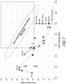
- FIG. 1 is a chart showing bend angles and yield strengths numerous commercial high pressure die cast (HPDC) alloys.
- the target alloy mechanical requirements in FIG. 1 are shown to be greater than 135 MPa yield strength and greater than 24 degree bend angle.
- FIG. 1 demonstrates that the commercial alloys either require heat treatment to meet the necessary mechanical requirements, or do not meet the necessary requirements.
- embodiments of the disclosure relate to casting aluminum alloys with both high yield strength and high ductility, without the need for post-casting heat treatment.
- the aluminum alloys were found to have high yield strength and high ductility compared to conventional, commercially available aluminum alloys.
- the aluminum alloys are described herein by the weight percent (wt %) of the total elements and particles within the alloy, as well as specific properties of the alloys. It will be understood that the remaining composition of any alloy described herein is aluminum and incidental impurities.
- Impurities may be present in the starting materials or introduced in one of the processing and/or manufacturing steps to create the aluminum alloy.
- Incidental impurities are compounds and/or elements that do not or do not substantially affect the material properties of the composition, such as yield strength, ductility and eliminating the need for heat treatment.
- the total incidental impurities are, are about, are at most, or are at most about, 1 wt.%, 0.5 wt.%, 0.2 wt.% 0.1 wt.%, 0.05 wt.% or 0.01 wt.%, or any range of values therebetween.
- the total incidental impurities are, are about, are at most, or are at most about, 1 wt.%, 0.5 wt.%, 0.2 wt.% 0.1 wt.%, 0.05 wt.% or 0.01 wt.%, or any range of values therebetween.
- each elemental incidental impurity is, is about, is at most, or is at most about, 0.5 wt.%, 0.2 wt.% 0.1 wt.%, 0.05 wt.%, 0.01 wt.%, 0.005 wt.% or 0.001 wt.%, or any range of values therebetween.
- the aluminum alloy composition comprises Si in the range of, or of about, 6.5-7.5 wt %, Cu in the range of, or of about, 0.4-0.8 wt %, Mn in the range of, or of about, 0.3-0.7 wt %, Mg in the range of, or of about, 0.2-0.4 wt %, Fe of at most, or of at most about, 0.4 wt %, V in the range of, or of about, 0.05-0.15 wt %, Sr in the range of, or of about, 0.01-0.03 wt %, Ti of at most, or of at most about, 0.15 wt %, Cr of at most, or of at most about, 0.03 wt %, with the remaining composition (by wt %) being Al and incidental impurities, wherein the maximum incidental impurities total 0.15 or 0.1 wt %.
- each elemental incidental impurity is, is about, is at most,
- the aluminum alloy composition comprises Si in the range of, or of about, 6.5-11 wt %, Cu in the range of, or of about, 0.3-0.8 wt %, Mn in the range of, or of about, 0.3-0.8 wt %, Mg in the range of, or of about, 0.1-0.4 wt %, Fe of at most, or of at most about, 0.5 wt %, V in the range of, or of about, 0.05-0.15 wt %, Sr in the range of, or of about, 0.01-0.05 wt %, Ti of at most, or of at most about, 0.15 wt %, Cr of at most, or of at most about, 0.03 wt %, with the remaining composition (by wt %) being Al and incidental impurities, wherein the maximum incidental impurities total 0.15 or 0.1 wt %.
- each elemental incidental impurity is, is about, is at most, or is
- the aluminum alloy composition comprises silicon (Si) in an amount of, of about, of at most, or of at most about, 15 wt.%, 13 wt.%, 12 wt.%, 11 wt.%, 10 wt.%, 9 wt.%, 8 wt.%, 7 wt.%, 6 wt.%, 5 wt.% or 3 wt.%, or any range of values therebetween.
- the aluminum alloy composition comprises copper (Cu) in an amount of, of about, of at most, or of at most about, 1 wt.%, 0.9 wt.%, 0.8 wt.%, 0.7 wt.%, 0.6 wt.%, 0.5 wt.%, 0.4 wt.%, 0.3 wt.%, 0.2 wt.% or 0.1 wt.%, or any range of values therebetween.
- the aluminum alloy composition comprises manganese (Mn) in an amount of, of about, of at most, or of at most about, 0.6 wt.%, 0.5 wt.%, 0.45 wt.%, 0.4 wt.%, 0.35 wt.%, 0.3 wt.%, 0.25 wt.%, 0.2 wt.%, 0.15 wt.%, 0.1 wt.% or 0.05 wt.%, or any range of values therebetween.
- Mn manganese
- the aluminum alloy composition comprises iron (Fe) in an amount of, of about, of at most, or of at most about, 0.8 wt.%, 0.7 wt.%, 0.6 wt.%, 0.5 wt.%, 0.4 wt.%, 0.3 wt.%, 0.2 wt.%, 0.1 wt.%, 0.05 wt.%, or 0.01 wt.%, or any range of values therebetween.
- iron (Fe) in an amount of, of about, of at most, or of at most about, 0.8 wt.%, 0.7 wt.%, 0.6 wt.%, 0.5 wt.%, 0.4 wt.%, 0.3 wt.%, 0.2 wt.%, 0.1 wt.%, 0.05 wt.%, or 0.01 wt.%, or any range of values therebetween.
- the aluminum alloy composition comprises vanadium (V) in an amount of, of about, of at most, or of at most about, 4 wt.%, 3 wt.%, 2.5 wt.%, 2 wt.%, 1.5 wt.%, 1 wt.%, 0.5 wt.%, 0.4 wt.%, 0.3 wt.%, 0.2 wt.%, 0.1 wt.% or 0.05 wt.%, or any range of values therebetween.
- V vanadium
- the aluminum alloy composition comprises strontium (Sr) in an amount of, of about, of at most, or of at most about, 0.1 wt.%, 0.08 wt.%, 0.07 wt.%, 0.06 wt.%, 0.05 wt.%, 0.045 wt.%, 0.04 wt.%, 0.035 wt.%, 0.03 wt.%, 0.025 wt.%, 0.02 wt.%, 0.015 wt.%, 0.01 wt.% or 0.005 wt.%, or any range of values therebetween.
- strontium Sr
- the aluminum alloy composition comprises titanium (Ti) in an amount of, of about, of at most, or of at most about, 0.3 wt.%, 0.2 wt.%, 0.15 wt.%, 0.14 wt.%, 0.13 wt.%, 0.12 wt.%, 0.1 wt.%, 0.08 wt.%, 0.07 wt.%, 0.06 wt.%, 0.05 wt.%, 0.04 wt.%, 0.03 wt.%, 0.02 wt.%, 0.01 wt.% or 0.005 wt.%, or any range of values therebetween.
- the aluminum alloy composition comprises chromium (Cr) in an amount of, of about, of at most, or of at most about, 0.1 wt.%, 0.07 wt.%, 0.05 wt.%, 0.04 wt.%, 0.03 wt.%, 0.02 wt.%, 0.01 wt.% or 0.005 wt.%, or any range of values therebetween.
- Cr chromium
- the aluminum alloy composition comprises each elemental incidental impurity in an amount of, of about, of at most, or of at most about, 0.1 wt.%, 0.07 wt.%, 0.05 wt.%, 0.04 wt.%, 0.03 wt.%, 0.02 wt.%, 0.01 wt.% or 0.005 wt.%, or any range of values therebetween.
- the aluminum alloy composition comprises a maximum incidental impurities total in an amount of, of about, of at most, or of at most about, 0.3 wt.%, 0.2 wt.%, 0.15 wt.%, 0.1 wt.%, 0.07 wt.%, 0.05 wt.%, 0.04 wt.%, 0.03 wt.%, 0.02 wt.%, 0.01 wt.% or 0.005 wt.%, or any range of values therebetween.
- the aluminum alloy composition comprises a weight ratio of Cu:Mg in an amount of, or of about, 4:1, 3.5:1, 3:1, 2.5:1, 2:1, 1.5:1 or 1:1, or any range of values therebetween.
- the ⁇ -Al volume fraction of an alloy is, is about, is at least, or is at least about, 85%, 90%, 91%, 92%, 93%, 94%, 95%, 96%, 97%, 98% or 99%, or any range of values therebetween.
- the aluminum alloy composition comprises Mg 2 Si phases in, in about in less than, or less than about, 2 wt.%, 1.5 wt.%, 1 wt.%, 0.9 wt.%, 0.8 wt.%, 0.7 wt.%, 0.6 wt.%, 0.5 wt.%, 0.45 wt.%, 0.4 wt.%, 0.35 wt.%, 0.3 wt.%, 0.25 wt.%, 0.2 wt.%, 0.15 wt.%, 0.1 wt.%, 0.05 wt.%, 0.04 wt.%, 0.03 wt.%, 0.02 wt.%, 0.01 wt.% or 0.005 wt.%, or any range of values therebetween.
- the aluminum alloy composition comprises Al 2 Cu phases in, in about, in less than, or less than about, 2 wt.%, 1.7 wt.%, 1.5 wt.%, 1.4 wt.%, 1.3 wt.%, 1.2 wt.%, 1.1 wt.%, 1 wt.%, 0.9 wt.%, 0.8 wt.%, 0.7 wt.%, 0.6 wt.%, 0.5 wt.%, 0.45 wt.%, 0.4 wt.%, 0.35 wt.%, 0.3 wt.%, 0.25 wt.%, 0.2 wt.%, 0.15 wt.%, 0.1 wt.%, 0.05 wt.%, 0.04 wt.%, 0.03 wt.%, 0.02 wt.%, 0.01 wt.%, 0.008 wt.%, 0.005 wt.% or 0.001
- the aluminum alloy composition comprises AlCuMgSi phases in, in about, in at least, or in at least about, 2 wt.%, 1.7 wt.%, 1.5 wt.%, 1.4 wt.%, 1.3 wt.%, 1.2 wt.%, 1.1 wt.%, 1 wt.%, 0.9 wt.%, 0.8 wt.%, 0.7 wt.%, 0.6 wt.%, 0.5 wt.%, 0.45 wt.%, 0.4 wt.%, 0.35 wt.%, 0.3 wt.%, 0.25 wt.%, 0.2 wt.%, 0.15 wt.%, 0.1 wt.%, 0.05 wt.%, 0.04 wt.%, 0.03 wt.%, 0.02 wt.%, 0.01 wt.%, 0.008 wt.%, 0.005 wt.% or
- the aluminum alloy composition comprises AlFeSi phases in, in about, in less than, less than about, in at least, or in at least about, 6 wt.%, 5 wt.%, 4.5 wt.%, 4 wt.%, 3.7 wt.%, 3.5 wt.%, 3.4 wt.%, 3.2 wt.%, 3.1 wt.%, 3 wt.%, 2.9 wt.%, 2.8 wt.%, 2.7 wt.%, 2.6 wt.%, 2.5 wt.%, 2.4 wt.%, 2.2 wt.%, 2 wt.%, 1.8 wt.%, 1.5 wt.%, 1.2 wt.%, 1 wt.%, 0.9 wt.%, 0.8 wt.%, 0.7 wt.%, 0.6 wt.%, 0.5 wt.%, 0.45 wt.%,
- the yield strength of the aluminum alloys described herein are at least or at least about 120 MPa.
- the yield strength is, is about, is at least, or is at least about, 120 MPa, 125 MPa, 130 MPa, 135 MPa, 140 MPa, 145 MPa, 150 MPa, 155 MPa, 160 MPa, 165 MPa, 170 MPa, 180 MPa or 200 MPa, or any range of values therebetween.
- the yield strength is, or is about, 120 MPa, 125 MPa, 130 MPa, 135 MPa, 140 MPa, 145 MPa, 150 MPa, 155 MPa, 160 MPa, 165 MPa, 170 MPa, 180 MPa or 200 MPa, or any range of values therebetween.
- the ductility of metal alloy should also be considered such that the parts are reproducibly manufacturable by using a casting process.
- Ductility of an alloy may be measured by the bend angle and/or the elongation of the alloy, although bend angle is preferred.
- FIG. 3A is a plot of bend angles and ⁇ -aluminum volume fractions for alloys
- FIG. 3B is a plot of bend angles and magnesium/nickel content for alloys of some embodiments.
- bend angle of an alloy is, is about, is at least, or is at least about, 15°, 20°, 23°, 25°, 30°, 35°, 40°, or 50°, or any range of values therebetween. In some embodiments, bend angle is, or is about, 15°, 20°, 23°, 25°, 30°, 35°, 40°, 50° or 60°, or any range of values therebetween. In some embodiments, the bend angle is measured at a 3 mm section thickness. In some embodiments, the bend angle is measured using the VDA238-100 evaluation standards. In some embodiments,
- the as-cast aluminum alloy In addition to sufficient yield strength and ductility when cast, the as-cast aluminum alloy must provide sufficient flowability and resistance to hot tearing and shrinkage cracking when high pressure die cast (HPDC). Unless specified otherwise, flow lengths described herein are under HPDC conditions. In a metal casting process, the metal alloy must have sufficient flowability to flow into and fill all intricacies of the mold. In molds with narrow and/or long mold channels, a sufficiently high flowability of the alloy is required to fill the mold.
- FIG. 4 is a bar chart showing the predicted and tested normalized flow lengths under HPDC conditions of alloys of some embodiments.
- Hot tearing and shrinkage cracking are common and catastrophic defects observed when casting alloys, including aluminum alloys. Without being able to prevent hot tearing in alloy, reliable and reproducible parts cannot be created. Hot tearing is the formation of an irreversible crack while the cast part is still in the semisolid casting. Although hot tearing is often associated with the casting process itself-linked to the creation of thermal stresses during the shrinkage of the melt flow during solidification, the underlying thermodynamics and microstructure of the alloy plays a part.
- the alloy has a casting flow length under HPDC conditions of, of about, of at least, or of at least about, 1 m, 1.1 m, 1.2 m, 1.3 m, 1.4 m, 1.5 m, 1.6 m, 1.7 m, 1.8 m, 1.9 m, 2 m, 2.2 m, 2.5 m, 3 m or 5 m, or any range of values therebetween.
- the alloy does not, or does not substantially, develop hot tears and/or shrinkage cracks throughout the casting flow length.
- the as-cast alloys are resistant to corrosion and/or oxidation.
- the alloy has an oxygen reduction factor (ORF) with respect to A380 kinetics of, of about, of at most, or of at most about, 2, 1.5, 1, 0.9, 0.8, 0.7, 0.6, 0.5, 0.4, 0.3, 0.2 or 0.1, or any range of values therebetween.
- ORF oxygen reduction factor
- a melt for an alloy can be prepared by heating the alloy above the melting temperature of the alloy components. As the melt is cast and cooled to room temperature, the alloys may go through cooling at various rates.
- the processing conditions can create larger or smaller grain sizes, increase or decrease the size and number of precipitates, and help minimize as-cast segregation.
- the alloy is die-cast. In some embodiments, the alloy is high pressure die-cast (HPDC). In certain embodiments, the aluminum alloy is cast without further processing. In some embodiments, the as-cast aluminum alloy is not further processed through heat treatment, and maintains the yield strength and ductility as mentioned above. In other embodiments, the as-cast aluminum alloy is further processed. In some embodiments, further processing methods include heat treating, aging, solution treating and surface finishing.
- the after the aluminum-alloy melt has been formed it may be cast into a die to form a high-performance product or part.
- product can be part of an automobile, such as parts of chassis and/or other crash components.
- Predictive models were performed to calculate yield strengths and ductility (e.g. bend angle) of aluminum alloy cast without further heat treatment processing.
- a number of predictive aluminum alloy compositions were created and experimentally tested for their as-cast yield strengths and ductility without heat treatment, including compositions 3C1, 3C3a, 3C3b, 3C4, 3C5, 3C6, 3C7, 3C8, 3C9 and 3C10.
- the results of these experimental tests are shown in FIG. 5 , which is a plot showing bend angles and yield strengths of alloy compositions 3C1, 3C3a, 3C3b, 3C4, 3C5, 3C6, 3C7, 3C8, 3C9 and 3C10.
- the elemental weight percent compositions of alloy compositions 3C1, 3C3a, 3C3b, 3C4, 3C5, 3C6, 3C7, 3C8, 3C9 and 3C10, with the remainder of the compositions being aluminum, are shown below in Table 1.
- the as-cast aluminum alloy composition of 3C10 was found to have a yield strength of about 143 MPa and a bend angle of about 25°, and the composition of aluminum alloy 3C10 that falls within Alloys 1, 2 and 3 shown below in Table 2.
- silicon content is relatively high, at about 8-12 wt.% in order to have sufficient flowability when cast. This is because the relative increase of heat of fusion attributed to silicon content allows an increase in latent heat contribution such that heat may be retained within the alloy system when cast, and therefore the alloy may retain its liquid phase for enough time to achieve sufficient casting lengths.
- silicon concentrations are necessary for flowability when the alloy is cast in HPDC condition.
- FIG. 6A is a bar chart showing experimental results of flow lengths and silicon content for alloys of some embodiments under HPDC conditions through a 3 mm section thickness. Castings were made using an about 700 ton high pressure die casting machine and a die designed to maintain even flow front for a 3mm thick casting up to 2 m in length. The various alloys were tested with the same casting conditions and the castings flow length was quantified.
- FIG. 6A shows that an alloy composition with 7.5 wt.% silicon had a flow length of about 1.4 meters, an alloy composition with 8.5 wt.% silicon had a flow length of about 1.45 meters, and an alloy composition with 9.5 wt.% silicon had a flow length of about 1.45 meters.
- silicon ranges for the alloy composition should be maintained over 6 wt.% to achieve advantageous flow lengths, but could be less than 11 wt.% (e.g. 8 wt.% or 7.5 wt.%) to minimize eutectic silicon phase's effect on reducing ductility.
- FIG. 6B is a line graph showing calculated results demonstrating the relationship between bend angle and FCC (i.e. aluminum matrix) mole fraction as a function of silicon content for alloys of some embodiments. Whereas FCC of aluminum is the most ductile phase present in the alloy composition, the silicon eutectic phase is a relatively more brittle phase. FIG. 6B demonstrates such a relationship between aluminum and silicon, where increasing silicon content of the alloy results in a reduction in the FCC mole fraction and bend angle.
- FCC i.e. aluminum matrix
- FIG. 7 is a predictive model chart showing yield strengths at Cu:Mg ratios of 3:1 at various magnesium and silicon weight percentages for alloys of some embodiments.
- increases in copper, magnesium and/or silicon are calculated to increase yield strengths of the alloy in part through the formation of strengthening precipitates (e.g. Mg 2 Si, Al 2 Cu and AlCuMgSi)
- strengthening precipitates e.g. Mg 2 Si, Al 2 Cu and AlCuMgSi
- FIG. 7 demonstrates that alloys within the silicon compositional ranges of Alloys 1, 2 or 3 of Table 2 and a Cu:Mg ratio of about 3:1 (e.g. 2:1 to 4:1) carefully balances yield strength and ductility.
- Such a Cu:Mg ratio selection unexpectedly and advantageously promotes the formation of the AlCuMgSi precipitate, which improves the alloys yield strength without substantially hindering ductility relative to other precipitates (e.g. Mg 2 Si and/or Al 2 Cu).
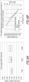
- FIG. 8A is a plot showing experimental results of bend angles for alloys of some embodiments including various magnesium and strontium amounts. As demonstrated, magnesium solute content and Mg 2 Si are both contributors to yield strength, but have negative effects on ductility.
- FIG. 8B is a plot showing experimental results of tensile yield strength and bend angles for alloys of some embodiments with varying copper and magnesium weight percentages. As demonstrated, cast 3 mm coupon results matched predictions shown in FIG. 7 of improved yield strengths decreased ductility associated with increased magnesium content.
- FIGS. 9A and 9B are optical micrograph cross-sectional images of a comparative alloy and an alloy of the present disclosure, respectively, wherein indicated phases were located and analyzed using energy-dispersive X-ray spectroscopy (EDS).
- the comparative alloy of FIG. 9A includes less than 0.05 wt.% vanadium, which is outside of the range of Alloys 1, 2 and 3 of Table 2.
- FIG. 9A includes less than 0.05 wt.% vanadium, which is outside of the range of Alloys 1, 2 and 3 of Table 2.
- feature 902 is a AlFeSi(Mn) phase shown with a plate morphology that was found to include less than 0.2 wt.% V
- feature 904 is a AlFeSi(Mn + V) phase with globular morphology more favorable for ductility that was found to include greater than 1.2 wt.% V.
- increased sharp morphological features e.g. plate morphologies
- iron impurities increase alloy crack initiation and propagation.
- the alloy of FIG. 9B shows a decrease in plate morphologies, and generally shows feature 906 of AlFeSi(Mn + V) phase with globular morphology more favorable for ductility, which was found to include greater than 1.2 wt.% V.
- vanadium and manganese may be used to reduce iron impurity solubility and stabilize AlFeSi(Mn,V) phases that have a rounded morphology. This allows the alloy to maintain high ductility performance with higher tolerances of Fe.
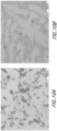
- FIG. 10A is an optical micrograph cross-sectional image of an aluminum and silicon alloy with 9.5 wt.% silicon and remainder of aluminum and incidental impurities
- FIG. 10B is an optical micrograph cross-sectional image of an aluminum, silicon and strontium alloy with 9.5 wt.% silicon, added strontium and remainder of aluminum and incidental impurities. While FIG. 10A shows silicon eutectic phases with sharp morphologies known to reduce ductility, the use of a strontium alloy the modifier in FIG. 10B is shown to blunt the silicon phase growth and create an alloy with more rounded morphologies favorable for ductility.
Landscapes
- Chemical & Material Sciences (AREA)
- Mechanical Engineering (AREA)
- Engineering & Computer Science (AREA)
- Organic Chemistry (AREA)
- Metallurgy (AREA)
- Materials Engineering (AREA)
- Crystallography & Structural Chemistry (AREA)
- Physics & Mathematics (AREA)
- Thermal Sciences (AREA)
- Continuous Casting (AREA)
- Superconductors And Manufacturing Methods Therefor (AREA)
- Extrusion Of Metal (AREA)
- Body Structure For Vehicles (AREA)
Abstract
Description
- The present invention relates to aluminum alloys. More specifically, the present invention relates to aluminum alloys with improved strength, ductility, and castability for high-performance applications including automobile parts.
- Commercial cast aluminum alloys for certain applications, for example structural components within an electric vehicle chassis, generally require both high strength and ductility. It is desirable to form these parts through a casting process, such that the parts may be cast quickly and reliably, such as through a high pressure die casting process. After casting, suitable alloys should maintain their structural properties sufficiently for the necessary application. Poor castability of the alloy often results in observed hot tearing, and can cause fill issues which typically decreases the mechanical properties of the part that results from the casting process. Furthermore, many structural components that are die cast may require heat treating, quenching, solution treating or aging the component after being cast to improve strength or ductility. However, heat treatment may require a large capital expenditure, long process time, and can cause costly yield loss. These issues are compounded by large part sizes which may be complicated to put through a heat treatment process, such as a quenching process.
-
US 2017/107599 A1 describes copper-free aluminum alloys suitable for high pressure die casting and capable of age-hardening under elevated temperatures. - The invention is set out in the claims. It may be desirable to produce cast aluminum alloys with high yield strengths such that the alloys do not fail easily, while also containing sufficient ductility. Furthermore, it may be desirable to produce cast aluminum alloys that do not require a heat treatment.
- For purposes of summarizing the disclosure and the advantages achieved over the prior art, certain objects and advantages of the disclosure are described herein. Not all such objects or advantages may be achieved in any particular embodiment. Thus, for example, those skilled in the art will recognize that the invention may be embodied or carried out in a manner that achieves or optimizes one advantage or group of advantages as taught herein without necessarily achieving other objects or advantages as may be taught or suggested herein.
- All of these embodiments are intended to be within the scope of the invention herein disclosed. These and other embodiments will become readily apparent to those skilled in the art from the following detailed description of the preferred embodiments having reference to the attached figures, the invention not being limited to any particular preferred embodiment(s) disclosed.
- In one aspect, an alloy composition is described. The alloy composition includes Al, wherein the alloy comprises a yield strength of at least about 130 MPa and a bend angle of at least about 20° at a 3 mm section thickness when as-cast and without further processing.
- In some embodiments, the alloy comprises a yield strength of at least about 130 MPa when as-cast and without further processing. In some embodiments, the alloy comprises a bend angle of at least about 24° at a 3 mm section thickness when as-cast and without further processing. In some embodiments, the alloy comprises a flow length of at least about 1.8 m. In some embodiments, the alloy comprises an α-Al volume fraction of at least about 90%.
- In some embodiments, the alloy comprises about 0.03 wt.% to about 0.25 wt.% of Mg2Si phases. In some embodiments, the alloy comprises about 0.01 wt.% to about 0.9 wt.% of Al2Cu phases. In some embodiments, the alloy comprises about 0.03 wt.% to about 0.2 wt.% of AlCuMgSi phases. In some embodiments, the alloy comprises about 0.3 wt.% to about 3 wt.% of AlFeSi phases. In some embodiments, the alloy composition further comprises Cu and Mg, wherein a weight ratio of Cu:Mg is about 4:1 to about 1:1. In some embodiments, the alloy has an oxygen reduction factor (ORF) with respect to A380 kinetics of at most about 1.
- In some embodiments, the alloy composition further comprises one or more of:
- Si at about 6.5-7.5 wt.%;
- Cu at about 0.4-0.8 wt.%;
- Mn at about 0.3-0.7 wt.%;
- Mg at about 0.1-0.4 wt.%;
- Fe at most about 0.4 wt.%;
- V at about 0.05-0.15 wt.%;
- Sr at about 0.01-0.03 wt.%;
- Ti at most about 0.15 wt.%;
- Cr at most about 0.03 wt.%; and
- remainder Al and incidental impurities.
- In some embodiments, the alloy composition further comprises one or more of:
- Si at about 6.5-7.5 wt.%;
- Cu at about 0.4-0.8 wt.%;
- Mn at about 0.3-0.7 wt.%;
- Mg at about 0.1-0.4 wt.%;
- Fe at most about 0.4 wt.%;
- V at about 0.05-0.15 wt.%;
- Sr at about 0.01-0.03 wt.%;
- Ti at most about 0.15 wt.%;
- Cr at most about 0.03 wt.%; and
- remainder Al and incidental impurities.
- In some embodiments, the alloy composition further comprises one or more of:
- Si at about 6-11 wt.%;
- Cu at about 0.3-0.8 wt.%;
- Mn at about 0.3-0.8 wt.%;
- Mg at about 0.1-0.4 wt.%;
- Fe at most about 0.5 wt.%;
- V at about 0.05-0.15 wt.%;
- Sr at about 0.01-0.05 wt.%;
- Ti at most about 0.15 wt.%;
- Cr at most about 0.03 wt.%; and
- remainder Al and incidental impurities.
- In some embodiments, the incidental impurities are at most about 0.1 wt.%.
- In another aspect, an automobile article including the alloy composition is described. In some embodiments, the automobile article is an automobile chassis.
- In one aspect, a process for preparing an alloy is described. The process includes providing alloy components, wherein at least one of the alloy components comprises Al, melting the alloy components to form a melted alloy, and cooling the melted alloy to form an as-cast alloy, wherein the as-cast alloy comprises a yield strength of at least about 130 MPa and a bend angle of at least about 20° at a 3 mm section thickness.
- In some embodiments, further processing is not performed on the as-cast alloy. In some embodiments, the process further comprises die-casting the melted alloy. In some embodiments, die-casting is high-pressure die-casting (HPDC). In some embodiments, the process further comprises further processing the as-cast alloy to form a processed alloy. In some embodiments, the further processing step is selected from the group consisting of heat treating, aging, solution treating, surface finishing and combinations thereof.
-
-
FIG. 1 is a chart showing bend angles and yield strengths numerous commercial alloys and the target alloys of some embodiments. -
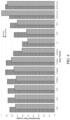
FIG. 2 is a bar chart showing the predicted and tested yield strengths of alloys of some embodiments. -
FIG. 3A is a plot of bend angles and α-aluminum volume fractions for alloys of some embodiments. -
FIG. 3B is a plot of bend angles and magnesium/nickel content for alloys of some embodiments. -
FIG. 4 is a bar chart showing the predicted and tested normalized flow lengths of alloys of some embodiments. -
FIG. 5 is a plot showing bend angles and yield strengths for alloys of some embodiments. -
FIG. 6A is a bar chart showing experimental results of flow lengths and silicon content for alloys of some embodiments. -
FIG. 6B is a line graph showing calculated results demonstrating the relationship between bend angle and FCC mole fraction as a function of silicon content for alloys of some embodiments. -
FIG. 7 is a predictive model chart showing yield strengths at Cu:Mg ratios of 3:1 at various magnesium and silicon weight percentages for alloys of some embodiments. -
FIG. 8A is a plot showing experimental results of bend angle for alloys of some embodiments including various magnesium and strontium amounts. -
FIG. 8B is a plot showing experimental results of tensile yield strength and bend angles for alloys of some embodiments with varying copper and magnesium weight percentages. -
FIG. 9A is an optical micrograph cross-sectional image of a comparative alloy. -
FIG. 9B is an optical micrograph cross-sectional image of an alloy according to some embodiments. -
FIG. 10A is an optical micrograph cross-sectional image of an aluminum and silicon alloy. -
FIG. 10B is an optical micrograph cross-sectional image of an aluminum, silicon and strontium alloy. - The present disclosure may be understood by reference to the following detailed description. It is noted that, for purposes of illustrative clarity, certain elements in various drawings may not be drawn to scale, may be represented schematically or conceptually, or otherwise may not correspond exactly to certain physical configurations of embodiments.
- Embodiments relate to aluminum alloys useful for creating products such as vehicle chassis or chassis components. In one embodiment, the vehicle is an electric vehicle powered by a battery pack. In one embodiment, the alloys were created to provide sufficient castability, and also provide relatively high yield strength and ductility, as well as eliminating the need for subsequent heat treatment of the cast alloy. In one embodiment, the alloy comprises a yield strength of at least about 130 MPa and a bend angle of at least about 20° at a 3 mm section thickness when as-cast and without further processing. In one embodiment, the aluminum alloys comprise vanadium to provide many of these enhancements. In another embodiment, the aluminum alloy has a specific weight ratio of copper to magnesium to provide many of these enhancements of an alloy with the desired features. In one embodiment, the aluminum alloy has a weight ratio of Cu:Mg of about 4:1 to about 1:1. In one embodiment, the aluminum alloy has a weight ratio of Cu:Mg of about 4:1 to about 2:1. As mentioned below, aluminum alloys with these compositions were found to have high yield strength and high ductility compared to available aluminum alloys. As mentioned below, the aluminum alloys are described herein by the weight percent (wt %) of the total elements and particles within the alloy, as well as specific properties of the alloys. It will be understood that the remaining composition of any alloy described herein is aluminum and incidental impurities.
-
FIG. 1 is a chart showing bend angles and yield strengths numerous commercial high pressure die cast (HPDC) alloys. The target alloy mechanical requirements inFIG. 1 are shown to be greater than 135 MPa yield strength and greater than 24 degree bend angle. However,FIG. 1 demonstrates that the commercial alloys either require heat treatment to meet the necessary mechanical requirements, or do not meet the necessary requirements. - In contrast, embodiments of the disclosure relate to casting aluminum alloys with both high yield strength and high ductility, without the need for post-casting heat treatment. The aluminum alloys were found to have high yield strength and high ductility compared to conventional, commercially available aluminum alloys. The aluminum alloys are described herein by the weight percent (wt %) of the total elements and particles within the alloy, as well as specific properties of the alloys. It will be understood that the remaining composition of any alloy described herein is aluminum and incidental impurities.
- Impurities may be present in the starting materials or introduced in one of the processing and/or manufacturing steps to create the aluminum alloy. Incidental impurities are compounds and/or elements that do not or do not substantially affect the material properties of the composition, such as yield strength, ductility and eliminating the need for heat treatment. In some embodiments, the total incidental impurities are, are about, are at most, or are at most about, 1 wt.%, 0.5 wt.%, 0.2 wt.% 0.1 wt.%, 0.05 wt.% or 0.01 wt.%, or any range of values therebetween. In embodiments, the total incidental impurities are, are about, are at most, or are at most about, 1 wt.%, 0.5 wt.%, 0.2 wt.% 0.1 wt.%, 0.05 wt.% or 0.01 wt.%, or any range of values therebetween. In some embodiments, each elemental incidental impurity is, is about, is at most, or is at most about, 0.5 wt.%, 0.2 wt.% 0.1 wt.%, 0.05 wt.%, 0.01 wt.%, 0.005 wt.% or 0.001 wt.%, or any range of values therebetween.
- In some embodiments, the aluminum alloy composition comprises Si in the range of, or of about, 6.5-7.5 wt %, Cu in the range of, or of about, 0.4-0.8 wt %, Mn in the range of, or of about, 0.3-0.7 wt %, Mg in the range of, or of about, 0.2-0.4 wt %, Fe of at most, or of at most about, 0.4 wt %, V in the range of, or of about, 0.05-0.15 wt %, Sr in the range of, or of about, 0.01-0.03 wt %, Ti of at most, or of at most about, 0.15 wt %, Cr of at most, or of at most about, 0.03 wt %, with the remaining composition (by wt %) being Al and incidental impurities, wherein the maximum incidental impurities total 0.15 or 0.1 wt %. In some embodiments, each elemental incidental impurity is, is about, is at most, or is at most about 0.05 wt %.
- In some embodiments, the aluminum alloy composition comprises Si in the range of, or of about, 6.5-11 wt %, Cu in the range of, or of about, 0.3-0.8 wt %, Mn in the range of, or of about, 0.3-0.8 wt %, Mg in the range of, or of about, 0.1-0.4 wt %, Fe of at most, or of at most about, 0.5 wt %, V in the range of, or of about, 0.05-0.15 wt %, Sr in the range of, or of about, 0.01-0.05 wt %, Ti of at most, or of at most about, 0.15 wt %, Cr of at most, or of at most about, 0.03 wt %, with the remaining composition (by wt %) being Al and incidental impurities, wherein the maximum incidental impurities total 0.15 or 0.1 wt %. In some embodiments, each elemental incidental impurity is, is about, is at most, or is at most about 0.05 wt %.
- In some embodiments, the aluminum alloy composition comprises silicon (Si) in an amount of, of about, of at most, or of at most about, 15 wt.%, 13 wt.%, 12 wt.%, 11 wt.%, 10 wt.%, 9 wt.%, 8 wt.%, 7 wt.%, 6 wt.%, 5 wt.% or 3 wt.%, or any range of values therebetween. In some embodiments, the aluminum alloy composition comprises copper (Cu) in an amount of, of about, of at most, or of at most about, 1 wt.%, 0.9 wt.%, 0.8 wt.%, 0.7 wt.%, 0.6 wt.%, 0.5 wt.%, 0.4 wt.%, 0.3 wt.%, 0.2 wt.% or 0.1 wt.%, or any range of values therebetween. In some embodiments, the aluminum alloy composition comprises manganese (Mn) in an amount of, of about, of at most, or of at most about, 0.6 wt.%, 0.5 wt.%, 0.45 wt.%, 0.4 wt.%, 0.35 wt.%, 0.3 wt.%, 0.25 wt.%, 0.2 wt.%, 0.15 wt.%, 0.1 wt.% or 0.05 wt.%, or any range of values therebetween. In some embodiments, the aluminum alloy composition comprises iron (Fe) in an amount of, of about, of at most, or of at most about, 0.8 wt.%, 0.7 wt.%, 0.6 wt.%, 0.5 wt.%, 0.4 wt.%, 0.3 wt.%, 0.2 wt.%, 0.1 wt.%, 0.05 wt.%, or 0.01 wt.%, or any range of values therebetween. In some embodiments, the aluminum alloy composition comprises vanadium (V) in an amount of, of about, of at most, or of at most about, 4 wt.%, 3 wt.%, 2.5 wt.%, 2 wt.%, 1.5 wt.%, 1 wt.%, 0.5 wt.%, 0.4 wt.%, 0.3 wt.%, 0.2 wt.%, 0.1 wt.% or 0.05 wt.%, or any range of values therebetween. In some embodiments, the aluminum alloy composition comprises strontium (Sr) in an amount of, of about, of at most, or of at most about, 0.1 wt.%, 0.08 wt.%, 0.07 wt.%, 0.06 wt.%, 0.05 wt.%, 0.045 wt.%, 0.04 wt.%, 0.035 wt.%, 0.03 wt.%, 0.025 wt.%, 0.02 wt.%, 0.015 wt.%, 0.01 wt.% or 0.005 wt.%, or any range of values therebetween. In some embodiments, the aluminum alloy composition comprises titanium (Ti) in an amount of, of about, of at most, or of at most about, 0.3 wt.%, 0.2 wt.%, 0.15 wt.%, 0.14 wt.%, 0.13 wt.%, 0.12 wt.%, 0.1 wt.%, 0.08 wt.%, 0.07 wt.%, 0.06 wt.%, 0.05 wt.%, 0.04 wt.%, 0.03 wt.%, 0.02 wt.%, 0.01 wt.% or 0.005 wt.%, or any range of values therebetween. In some embodiments, the aluminum alloy composition comprises chromium (Cr) in an amount of, of about, of at most, or of at most about, 0.1 wt.%, 0.07 wt.%, 0.05 wt.%, 0.04 wt.%, 0.03 wt.%, 0.02 wt.%, 0.01 wt.% or 0.005 wt.%, or any range of values therebetween. In some embodiments, the aluminum alloy composition comprises each elemental incidental impurity in an amount of, of about, of at most, or of at most about, 0.1 wt.%, 0.07 wt.%, 0.05 wt.%, 0.04 wt.%, 0.03 wt.%, 0.02 wt.%, 0.01 wt.% or 0.005 wt.%, or any range of values therebetween. In some embodiments, the aluminum alloy composition comprises a maximum incidental impurities total in an amount of, of about, of at most, or of at most about, 0.3 wt.%, 0.2 wt.%, 0.15 wt.%, 0.1 wt.%, 0.07 wt.%, 0.05 wt.%, 0.04 wt.%, 0.03 wt.%, 0.02 wt.%, 0.01 wt.% or 0.005 wt.%, or any range of values therebetween.
- In some embodiments, the aluminum alloy composition comprises a weight ratio of Cu:Mg in an amount of, or of about, 4:1, 3.5:1, 3:1, 2.5:1, 2:1, 1.5:1 or 1:1, or any range of values therebetween.
- In some embodiments, the α-Al volume fraction of an alloy is, is about, is at least, or is at least about, 85%, 90%, 91%, 92%, 93%, 94%, 95%, 96%, 97%, 98% or 99%, or any range of values therebetween.
- In some embodiments, the aluminum alloy composition comprises Mg2Si phases in, in about in less than, or less than about, 2 wt.%, 1.5 wt.%, 1 wt.%, 0.9 wt.%, 0.8 wt.%, 0.7 wt.%, 0.6 wt.%, 0.5 wt.%, 0.45 wt.%, 0.4 wt.%, 0.35 wt.%, 0.3 wt.%, 0.25 wt.%, 0.2 wt.%, 0.15 wt.%, 0.1 wt.%, 0.05 wt.%, 0.04 wt.%, 0.03 wt.%, 0.02 wt.%, 0.01 wt.% or 0.005 wt.%, or any range of values therebetween. In some embodiments, the aluminum alloy composition comprises Al2Cu phases in, in about, in less than, or less than about, 2 wt.%, 1.7 wt.%, 1.5 wt.%, 1.4 wt.%, 1.3 wt.%, 1.2 wt.%, 1.1 wt.%, 1 wt.%, 0.9 wt.%, 0.8 wt.%, 0.7 wt.%, 0.6 wt.%, 0.5 wt.%, 0.45 wt.%, 0.4 wt.%, 0.35 wt.%, 0.3 wt.%, 0.25 wt.%, 0.2 wt.%, 0.15 wt.%, 0.1 wt.%, 0.05 wt.%, 0.04 wt.%, 0.03 wt.%, 0.02 wt.%, 0.01 wt.%, 0.008 wt.%, 0.005 wt.% or 0.001 wt.%, or any range of values therebetween. In some embodiments, the aluminum alloy composition comprises AlCuMgSi phases in, in about, in at least, or in at least about, 2 wt.%, 1.7 wt.%, 1.5 wt.%, 1.4 wt.%, 1.3 wt.%, 1.2 wt.%, 1.1 wt.%, 1 wt.%, 0.9 wt.%, 0.8 wt.%, 0.7 wt.%, 0.6 wt.%, 0.5 wt.%, 0.45 wt.%, 0.4 wt.%, 0.35 wt.%, 0.3 wt.%, 0.25 wt.%, 0.2 wt.%, 0.15 wt.%, 0.1 wt.%, 0.05 wt.%, 0.04 wt.%, 0.03 wt.%, 0.02 wt.%, 0.01 wt.%, 0.008 wt.%, 0.005 wt.% or 0.001 wt.%, or any range of values therebetween. In some embodiments, the aluminum alloy composition comprises AlFeSi phases in, in about, in less than, less than about, in at least, or in at least about, 6 wt.%, 5 wt.%, 4.5 wt.%, 4 wt.%, 3.7 wt.%, 3.5 wt.%, 3.4 wt.%, 3.2 wt.%, 3.1 wt.%, 3 wt.%, 2.9 wt.%, 2.8 wt.%, 2.7 wt.%, 2.6 wt.%, 2.5 wt.%, 2.4 wt.%, 2.2 wt.%, 2 wt.%, 1.8 wt.%, 1.5 wt.%, 1.2 wt.%, 1 wt.%, 0.9 wt.%, 0.8 wt.%, 0.7 wt.%, 0.6 wt.%, 0.5 wt.%, 0.45 wt.%, 0.4 wt.%, 0.35 wt.%, 0.3 wt.%, 0.25 wt.%, 0.2 wt.%, 0.15 wt.%, 0.1 wt.% or 0.05 wt.%, or any range of values therebetween.
- Industrial applications in which thousands and hundreds-of-thousands of aluminum alloy parts may be cast can require high yield strength. As seen in,
FIG. 2 the predicted and tested yield strengths of alloys of embodiments 1B3, 2F5, 3D2, 3C1, 3I1, 365-3, 365-2, 1B4, 3C3a, 3C3b, 3I3a, 3I3b and 3D3 were evaluated. - The yield strength of the aluminum alloys described herein are at least or at least about 120 MPa. In some embodiments, the yield strength is, is about, is at least, or is at least about, 120 MPa, 125 MPa, 130 MPa, 135 MPa, 140 MPa, 145 MPa, 150 MPa, 155 MPa, 160 MPa, 165 MPa, 170 MPa, 180 MPa or 200 MPa, or any range of values therebetween. In some embodiments, the yield strength is, or is about, 120 MPa, 125 MPa, 130 MPa, 135 MPa, 140 MPa, 145 MPa, 150 MPa, 155 MPa, 160 MPa, 165 MPa, 170 MPa, 180 MPa or 200 MPa, or any range of values therebetween.
- The ductility of metal alloy should also be considered such that the parts are reproducibly manufacturable by using a casting process. Ductility of an alloy may be measured by the bend angle and/or the elongation of the alloy, although bend angle is preferred.
-
FIG. 3A is a plot of bend angles and α-aluminum volume fractions for alloys, andFIG. 3B is a plot of bend angles and magnesium/nickel content for alloys of some embodiments. - In some embodiments, bend angle of an alloy is, is about, is at least, or is at least about, 15°, 20°, 23°, 25°, 30°, 35°, 40°, or 50°, or any range of values therebetween. In some embodiments, bend angle is, or is about, 15°, 20°, 23°, 25°, 30°, 35°, 40°, 50° or 60°, or any range of values therebetween. In some embodiments, the bend angle is measured at a 3 mm section thickness. In some embodiments, the bend angle is measured using the VDA238-100 evaluation standards. In some embodiments,
- In addition to sufficient yield strength and ductility when cast, the as-cast aluminum alloy must provide sufficient flowability and resistance to hot tearing and shrinkage cracking when high pressure die cast (HPDC). Unless specified otherwise, flow lengths described herein are under HPDC conditions. In a metal casting process, the metal alloy must have sufficient flowability to flow into and fill all intricacies of the mold. In molds with narrow and/or long mold channels, a sufficiently high flowability of the alloy is required to fill the mold.
FIG. 4 is a bar chart showing the predicted and tested normalized flow lengths under HPDC conditions of alloys of some embodiments. - A formula for predicting the flow length of alloys within a sand casting under HPDC conditions is shown below.

- Hot tearing and shrinkage cracking are common and catastrophic defects observed when casting alloys, including aluminum alloys. Without being able to prevent hot tearing in alloy, reliable and reproducible parts cannot be created. Hot tearing is the formation of an irreversible crack while the cast part is still in the semisolid casting. Although hot tearing is often associated with the casting process itself-linked to the creation of thermal stresses during the shrinkage of the melt flow during solidification, the underlying thermodynamics and microstructure of the alloy plays a part.
- In some embodiments, the alloy has a casting flow length under HPDC conditions of, of about, of at least, or of at least about, 1 m, 1.1 m, 1.2 m, 1.3 m, 1.4 m, 1.5 m, 1.6 m, 1.7 m, 1.8 m, 1.9 m, 2 m, 2.2 m, 2.5 m, 3 m or 5 m, or any range of values therebetween. In some embodiments, the alloy does not, or does not substantially, develop hot tears and/or shrinkage cracks throughout the casting flow length.
- Structural castings are expected to last within punishing environments for automotive applications. In some embodiments, the as-cast alloys are resistant to corrosion and/or oxidation. In some embodiments, the alloy has an oxygen reduction factor (ORF) with respect to A380 kinetics of, of about, of at most, or of at most about, 2, 1.5, 1, 0.9, 0.8, 0.7, 0.6, 0.5, 0.4, 0.3, 0.2 or 0.1, or any range of values therebetween. A formula for calculating ORF is shown below.

- ai = current density associated with noble phase i (refer to Table 3)
- Vi = volume fraction of noble phase ε
- i A380 = oxygen reduction current density of cast 4380 (baseline alloy) at - 965 mVSCE
- In some embodiments, a melt for an alloy can be prepared by heating the alloy above the melting temperature of the alloy components. As the melt is cast and cooled to room temperature, the alloys may go through cooling at various rates. The processing conditions can create larger or smaller grain sizes, increase or decrease the size and number of precipitates, and help minimize as-cast segregation.
- In some embodiments, the alloy is die-cast. In some embodiments, the alloy is high pressure die-cast (HPDC). In certain embodiments, the aluminum alloy is cast without further processing. In some embodiments, the as-cast aluminum alloy is not further processed through heat treatment, and maintains the yield strength and ductility as mentioned above. In other embodiments, the as-cast aluminum alloy is further processed. In some embodiments, further processing methods include heat treating, aging, solution treating and surface finishing.
- In certain embodiments, the after the aluminum-alloy melt has been formed, it may be cast into a die to form a high-performance product or part. In some embodiments, product can be part of an automobile, such as parts of chassis and/or other crash components.
- Predictive models were performed to calculate yield strengths and ductility (e.g. bend angle) of aluminum alloy cast without further heat treatment processing. A number of predictive aluminum alloy compositions were created and experimentally tested for their as-cast yield strengths and ductility without heat treatment, including compositions 3C1, 3C3a, 3C3b, 3C4, 3C5, 3C6, 3C7, 3C8, 3C9 and 3C10. The results of these experimental tests are shown in
FIG. 5 , which is a plot showing bend angles and yield strengths of alloy compositions 3C1, 3C3a, 3C3b, 3C4, 3C5, 3C6, 3C7, 3C8, 3C9 and 3C10. - The elemental weight percent compositions of alloy compositions 3C1, 3C3a, 3C3b, 3C4, 3C5, 3C6, 3C7, 3C8, 3C9 and 3C10, with the remainder of the compositions being aluminum, are shown below in Table 1. The as-cast aluminum alloy composition of 3C10 was found to have a yield strength of about 143 MPa and a bend angle of about 25°, and the composition of aluminum alloy 3C10 that falls within
Alloys Table 1 Alloy ID Composition (wt%) Al Si Mg Mn Ni Cu Fe Ti Sn V Sr 3C1 Remain 6 - 1 - 0.5 0.2 - 0.05 - 0.03 3C3a Remain 7 - 0.45 - 0.8 0.2 - - - 0.03 3C3b Remain 7 0.3 0.45 - 0.8 0.2 - - - 0.03 3C4 Remain 6.5 0.25 0.35 - 0.75 0.2 0.1 - 0.15 0.03 3C5 Remain 5 0.3 0.35 - 0.9 0.2 0.10 - 0.15 0.03 3C6 Remain 6.5 0.15 0.35 - 0.45 0.2 0.10 - 0.15 0.03 3C7 Remain 6.5 0.15 0.35 0.05 0.45 0.2 0.10 - 0.15 0.03 3C8 Remain 6.5 0.15 0.35 - 0.45 0.2 - - 0.15 0.03 3C9 Remain 7 0.25 0.35 - 0.5 0.2 0.05 - 0.1 0.03 3C10 Remain 7 0.15 0.45 - 0.8 0.2 0.05 - 0.1 0.03 Table 2 Element Alloy 1 Alloy 2 Alloy 3 Al Remainder Remainder Remainder Si 6.5-7.5 wt.% 6-11 wt.% 6-11 wt.% Cu 0.4-0.8 wt.% 0.3-0.8 wt.% 0.3-0.8 wt.% Mn 0.35-0.7 wt.% 0.35-0.8 wt.% 0.35-0.8 wt.% Mg 0.1-0.4 wt.% 0.15-0.4 wt.% 0.1-0.4 wt.% Fe ≤ 0.4 wt.% ≤ 0.5 wt.% ≤ 0.5 wt.% V 0.05-0.15 wt.% 0.05-0.15 wt.% 0.05-0.15 wt.% Sr 0.015-0.03 wt.% 0.015-0.05 wt.% 0.015-0.05 wt.% Ti ≤ 0.15 wt.% ≤ 0.15 wt.% ≤ 0.15 wt.% Cr ≤ 0.03 wt.% ≤ 0.03 wt.% ≤ 0.03 wt.% Impurities 0-0.15 wt.% 0-0.15 wt.% 0-0.15 wt.% - Although increased silicon content is known to decrease the ductility of an alloy, under traditional die casting conditions for aluminum alloys, silicon content is relatively high, at about 8-12 wt.% in order to have sufficient flowability when cast. This is because the relative increase of heat of fusion attributed to silicon content allows an increase in latent heat contribution such that heat may be retained within the alloy system when cast, and therefore the alloy may retain its liquid phase for enough time to achieve sufficient casting lengths. However, it is not readily apparent if the same silicon concentrations are necessary for flowability when the alloy is cast in HPDC condition.
-
FIG. 6A is a bar chart showing experimental results of flow lengths and silicon content for alloys of some embodiments under HPDC conditions through a 3 mm section thickness. Castings were made using an about 700 ton high pressure die casting machine and a die designed to maintain even flow front for a 3mm thick casting up to 2 m in length. The various alloys were tested with the same casting conditions and the castings flow length was quantified. -
FIG. 6A shows that an alloy composition with 7.5 wt.% silicon had a flow length of about 1.4 meters, an alloy composition with 8.5 wt.% silicon had a flow length of about 1.45 meters, and an alloy composition with 9.5 wt.% silicon had a flow length of about 1.45 meters. As seen, there is a steep drop off in flowability gains of flow length for Si content over 7.5 wt%. Therefore, it was determined that silicon ranges for the alloy composition should be maintained over 6 wt.% to achieve advantageous flow lengths, but could be less than 11 wt.% (e.g. 8 wt.% or 7.5 wt.%) to minimize eutectic silicon phase's effect on reducing ductility. As such, under HPDC conditions it was discovered that increasing silicon content, relative to silicon content under traditional die casting conditions, did not necessarily improve flow length grow to as great of a degree. This discovery allowed the alloy silicon content to be reduced in order to achieve a HPDC case alloy with relatively longer flow lengths and an improved ductility. -
FIG. 6B is a line graph showing calculated results demonstrating the relationship between bend angle and FCC (i.e. aluminum matrix) mole fraction as a function of silicon content for alloys of some embodiments. Whereas FCC of aluminum is the most ductile phase present in the alloy composition, the silicon eutectic phase is a relatively more brittle phase.FIG. 6B demonstrates such a relationship between aluminum and silicon, where increasing silicon content of the alloy results in a reduction in the FCC mole fraction and bend angle. -
FIG. 7 is a predictive model chart showing yield strengths at Cu:Mg ratios of 3:1 at various magnesium and silicon weight percentages for alloys of some embodiments. Although increases in copper, magnesium and/or silicon are calculated to increase yield strengths of the alloy in part through the formation of strengthening precipitates (e.g. Mg2Si, Al2Cu and AlCuMgSi), decreased aluminum content typically leads to a decrease in alloy ductility. However,FIG. 7 demonstrates that alloys within the silicon compositional ranges ofAlloys -
FIG. 8A is a plot showing experimental results of bend angles for alloys of some embodiments including various magnesium and strontium amounts. As demonstrated, magnesium solute content and Mg2Si are both contributors to yield strength, but have negative effects on ductility. -
FIG. 8B is a plot showing experimental results of tensile yield strength and bend angles for alloys of some embodiments with varying copper and magnesium weight percentages. As demonstrated, cast 3 mm coupon results matched predictions shown inFIG. 7 of improved yield strengths decreased ductility associated with increased magnesium content. -
FIGS. 9A and 9B are optical micrograph cross-sectional images of a comparative alloy and an alloy of the present disclosure, respectively, wherein indicated phases were located and analyzed using energy-dispersive X-ray spectroscopy (EDS). The comparative alloy ofFIG. 9A includes less than 0.05 wt.% vanadium, which is outside of the range ofAlloys FIG. 9A , feature 902 is a AlFeSi(Mn) phase shown with a plate morphology that was found to include less than 0.2 wt.% V, and feature 904 is a AlFeSi(Mn + V) phase with globular morphology more favorable for ductility that was found to include greater than 1.2 wt.% V. A person of ordinary skill in the art would appreciate that increased sharp morphological features (e.g. plate morphologies) in part caused by iron impurities increase alloy crack initiation and propagation. - In contrast, the alloy of
FIG. 9B shows a decrease in plate morphologies, and generally showsfeature 906 of AlFeSi(Mn + V) phase with globular morphology more favorable for ductility, which was found to include greater than 1.2 wt.% V. As such, it is demonstrated that vanadium and manganese may be used to reduce iron impurity solubility and stabilize AlFeSi(Mn,V) phases that have a rounded morphology. This allows the alloy to maintain high ductility performance with higher tolerances of Fe. -
FIG. 10A is an optical micrograph cross-sectional image of an aluminum and silicon alloy with 9.5 wt.% silicon and remainder of aluminum and incidental impurities, andFIG. 10B is an optical micrograph cross-sectional image of an aluminum, silicon and strontium alloy with 9.5 wt.% silicon, added strontium and remainder of aluminum and incidental impurities. WhileFIG. 10A shows silicon eutectic phases with sharp morphologies known to reduce ductility, the use of a strontium alloy the modifier inFIG. 10B is shown to blunt the silicon phase growth and create an alloy with more rounded morphologies favorable for ductility. - Features, materials, characteristics, or groups described in conjunction with a particular aspect, embodiment, or example are to be understood to be applicable to any other aspect, embodiment or example described in this section or elsewhere in this specification unless incompatible therewith. All of the features disclosed in this specification (including any accompanying claims, abstract and drawings), and/or all of the steps of any method or process so disclosed, may be combined in any combination, except combinations where at least some of such features and/or steps are mutually exclusive. The protection is not restricted to the details of any foregoing embodiments. The protection extends to any novel one, or any novel combination, of the features disclosed in this specification (including any accompanying claims, abstract and drawings), or to any novel one, or any novel combination, of the steps of any method or process so disclosed.
- Furthermore, certain features that are described in this disclosure in the context of separate implementations can also be implemented in combination in a single implementation. Conversely, various features that are described in the context of a single implementation can also be implemented in multiple implementations separately or in any suitable subcombination. Moreover, although features may be described above as acting in certain combinations, one or more features from a claimed combination can, in some cases, be excised from the combination, and the combination may be claimed as a subcombination or variation of a subcombination.
- Moreover, while operations may be depicted in the drawings or described in the specification in a particular order, such operations need not be performed in the particular order shown or in sequential order, or that all operations be performed, to achieve desirable results. Other operations that are not depicted or described can be incorporated in the example methods and processes. For example, one or more additional operations can be performed before, after, simultaneously, or between any of the described operations. Further, the operations may be rearranged or reordered in other implementations. Those skilled in the art will appreciate that in some embodiments, the actual steps taken in the processes illustrated and/or disclosed may differ from those shown in the figures. Depending on the embodiment, certain of the steps described above may be removed, others may be added. Furthermore, the features and attributes of the specific embodiments disclosed above may be combined in different ways to form additional embodiments, all of which fall within the scope of the present disclosure. Also, the separation of various system components in the implementations described above should not be understood as requiring such separation in all implementations, and it should be understood that the described components and systems can generally be integrated together in a single product or packaged into multiple products. For example, any of the components for an energy storage system described herein can be provided separately, or integrated together (e.g., packaged together, or attached together) to form an energy storage system.
- For purposes of this disclosure, certain aspects, advantages, and novel features are described herein. Not necessarily all such advantages may be achieved in accordance with any particular embodiment. Thus, for example, those skilled in the art will recognize that the disclosure may be embodied or carried out in a manner that achieves one advantage or a group of advantages as taught herein without necessarily achieving other advantages as may be taught or suggested herein.
- Conditional language, such as "can," "could," "might," or "may," unless specifically stated otherwise, or otherwise understood within the context as used, is generally intended to convey that certain embodiments include, while other embodiments do not include, certain features, elements, and/or steps. Thus, such conditional language is not generally intended to imply that features, elements, and/or steps are in any way required for one or more embodiments or that one or more embodiments necessarily include logic for deciding, with or without user input or prompting, whether these features, elements, and/or steps are included or are to be performed in any particular embodiment.
- Conjunctive language such as the phrase "at least one of X, Y, and Z," unless specifically stated otherwise, is otherwise understood with the context as used in general to convey that an item, term, etc. may be either X, Y, or Z. Thus, such conjunctive language is not generally intended to imply that certain embodiments require the presence of at least one of X, at least one of Y, and at least one of Z.
- Language of degree used herein, such as the terms "approximately," "about," "generally," and "substantially" as used herein represent a value, amount, or characteristic close to the stated value, amount, or characteristic that still performs a desired function or achieves a desired result. For example, the terms "approximately," "about," "generally," and "substantially" may refer to an amount that is within less than 10% of, within less than 5% of, within less than 1% of, within less than 0.1% of, and within less than 0.01% of the stated amount, depending on the desired function or desired result.
Claims (15)
- An alloy composition, comprising:Al;wherein the alloy comprises a yield strength of at least about 130 MPa and a bend angle of at least about 20° at a 3 mm section thickness when as-cast and without further processing.
- The composition of Claim 1, wherein the alloy comprises a yield strength of at least about 130 MPa when as-cast and without further processing.
- The composition of Claim 1 or 2, wherein the alloy comprises a bend angle of at least about 24° at a 3 mm section thickness when as-cast and without further processing.
- The composition of one of the preceding claims, wherein the alloy comprises a flow length of at least about 1.8 m.
- The composition of one of the preceding claims, wherein the alloy comprises an α-Al volume fraction of at least about 90%.
- The composition of one of the preceding claims, wherein the alloy comprises about 0.03 wt.% to about 0.25 wt.% of Mg2Si phases.
- The composition of one of the preceding claims, wherein the alloy comprises about 0.01 wt.% to about 0.9 wt.% of Al2Cu phases.
- The composition of one of the preceding claims, wherein the alloy comprises about 0.03 wt.% to about 0.2 wt.% of AlCuMgSi phases.
- The composition of one of the preceding claims, wherein the alloy comprises about 0.3 wt.% to about 3 wt.% of AlFeSi phases.
- The composition of one of the preceding claims, further comprising Cu and Mg, wherein a weight ratio of Cu:Mg is about 4:1 to about 2:1.
- A process for preparing an alloy, comprising:providing alloy components, wherein at least one of the alloy components comprises Al;melting the alloy components to form a melted alloy; andcooling the melted alloy to form an as-cast alloy;wherein the as-cast alloy comprises a yield strength of at least about 130 MPa and a bend angle of at least about 20° at a 3 mm section thickness.
- The process of Claim 11, wherein further processing is not performed on the as-cast alloy.
- The process of Claim 11 or 12, further comprising die-casting the melted alloy.
- The process of Claim 13, wherein die-casting is high-pressure die-casting (HPDC).
- The process of one of claims 11 to 14, further comprising further processing the as-cast alloy to form a processed alloy.
Applications Claiming Priority (4)
| Application Number | Priority Date | Filing Date | Title |
|---|---|---|---|
| US202062964554P | 2020-01-22 | 2020-01-22 | |
| US202063093608P | 2020-10-19 | 2020-10-19 | |
| EP21704681.2A EP4093894B1 (en) | 2020-01-22 | 2021-01-20 | Die cast aluminum alloys for structural components |
| PCT/US2021/014177 WO2021150604A1 (en) | 2020-01-22 | 2021-01-20 | Die cast aluminum alloys for structural components |
Related Parent Applications (1)
| Application Number | Title | Priority Date | Filing Date |
|---|---|---|---|
| EP21704681.2A Division EP4093894B1 (en) | 2020-01-22 | 2021-01-20 | Die cast aluminum alloys for structural components |
Publications (2)
| Publication Number | Publication Date |
|---|---|
| EP4461435A2 true EP4461435A2 (en) | 2024-11-13 |
| EP4461435A3 EP4461435A3 (en) | 2025-02-19 |
Family
ID=74587149
Family Applications (2)
| Application Number | Title | Priority Date | Filing Date |
|---|---|---|---|
| EP21704681.2A Active EP4093894B1 (en) | 2020-01-22 | 2021-01-20 | Die cast aluminum alloys for structural components |
| EP24202086.5A Pending EP4461435A3 (en) | 2020-01-22 | 2021-01-20 | Die cast aluminum alloys for structural components |
Family Applications Before (1)
| Application Number | Title | Priority Date | Filing Date |
|---|---|---|---|
| EP21704681.2A Active EP4093894B1 (en) | 2020-01-22 | 2021-01-20 | Die cast aluminum alloys for structural components |
Country Status (7)
| Country | Link |
|---|---|
| US (1) | US20230046008A1 (en) |
| EP (2) | EP4093894B1 (en) |
| JP (2) | JP7728766B2 (en) |
| KR (1) | KR20220129568A (en) |
| CN (1) | CN115003832A (en) |
| ES (1) | ES3004343T3 (en) |
| WO (1) | WO2021150604A1 (en) |
Families Citing this family (5)
| Publication number | Priority date | Publication date | Assignee | Title |
|---|---|---|---|---|
| JP2024539658A (en) * | 2021-10-18 | 2024-10-29 | コリア インスティテュート オブ マテリアルズ サイエンス | High strength, highly elongated and highly thermally conductive aluminum casting alloy and its method of manufacture |
| KR102810780B1 (en) * | 2021-10-18 | 2025-05-26 | 한국재료연구원 | Aluminum cast alloy having high strength, high elongation and high heat conductivity and method of fabricating the same |
| CN114411020B (en) * | 2022-01-13 | 2022-10-14 | 上海交通大学 | A kind of non-heat treatment strengthened high-strength and high-toughness die-casting aluminum-silicon alloy |
| CN114574734B (en) * | 2022-03-01 | 2022-09-27 | 重庆工商大学 | A kind of high-strength cast aluminum alloy containing yttrium and samarium and preparation method thereof |
| CN116287891B (en) * | 2023-05-25 | 2023-08-08 | 小米汽车科技有限公司 | A heat-free die-casting aluminum alloy and its preparation method and application |
Citations (1)
| Publication number | Priority date | Publication date | Assignee | Title |
|---|---|---|---|---|
| US20170107599A1 (en) | 2015-10-19 | 2017-04-20 | GM Global Technology Operations LLC | New high pressure die casting aluminum alloy for high temperature and corrosive applications |
Family Cites Families (23)
| Publication number | Priority date | Publication date | Assignee | Title |
|---|---|---|---|---|
| JPH06228719A (en) * | 1993-02-01 | 1994-08-16 | Nippon Light Metal Co Ltd | Formation of bent part in aluminum alloy casting, and high rigidity aluminum alloy casting and its production |
| JPH11293375A (en) * | 1998-04-14 | 1999-10-26 | Hitachi Metals Ltd | Aluminum alloy die casting with high toughness and its production |
| DE10323741B3 (en) | 2003-05-24 | 2004-10-14 | Daimlerchrysler Ag | Aluminum casting alloy for the production of e.g. pistons of IC engines contains alloying additions of silicon, magnesium, zirconium, hafnium and titanium |
| JP2006183122A (en) * | 2004-12-28 | 2006-07-13 | Denso Corp | Aluminum alloy for die casting and method for producing aluminum alloy casting |
| EP2758557B1 (en) | 2011-09-19 | 2015-11-04 | Alcoa GmbH | Improved aluminum casting alloys containing vanadium |
| CN102676887B (en) * | 2012-06-11 | 2014-04-16 | 东莞市闻誉实业有限公司 | Aluminum alloy for pressure casting and casting of the aluminum alloy |
| CN103305730A (en) * | 2013-05-16 | 2013-09-18 | 天津立中合金集团有限公司 | Novel Al-Si-Mg-Cu-Sr cast alloy |
| WO2015126515A2 (en) * | 2013-12-20 | 2015-08-27 | Alcoa Inc. | HIGH PERFORMANCE AlSiMgCu CASTING ALLOY |
| FR3036986B1 (en) * | 2015-06-05 | 2017-05-26 | Constellium Neuf-Brisach | BODY FOR CAR BODY WITH HIGH MECHANICAL STRENGTH |
| DE102015007929A1 (en) * | 2015-06-20 | 2016-12-22 | Daimler Ag | Cast aluminum alloy, method of manufacturing an aluminum cast alloy component and using an aluminum casting alloy |
| ES3066613T3 (en) * | 2015-08-13 | 2026-05-13 | Alcoa Usa Corp | 3xx aluminum casting alloy, and shape cast product made therefrom |
| JP6506678B2 (en) | 2015-11-02 | 2019-04-24 | 株式会社神戸製鋼所 | Aluminum alloy sheet for automobile structural member and method of manufacturing the same |
| KR20170125984A (en) * | 2015-12-18 | 2017-11-15 | 노벨리스 인크. | High-Strength 6XXX Aluminum Alloys and Manufacturing Method Thereof |
| JP2017133044A (en) * | 2016-01-25 | 2017-08-03 | 株式会社神戸製鋼所 | Aluminum alloy sheet and aluminum alloy structural member |
| EP3235916B1 (en) * | 2016-04-19 | 2018-08-15 | Rheinfelden Alloys GmbH & Co. KG | Cast alloy |
| WO2017185321A1 (en) * | 2016-04-29 | 2017-11-02 | GM Global Technology Operations LLC | Die-casting aluminum alloys for thin-wall casting components |
| EP3464659B2 (en) * | 2016-06-01 | 2023-07-12 | Aleris Aluminum Duffel BVBA | 6xxx-series aluminium alloy forging stock material and method of manufacting thereof |
| US20180010214A1 (en) | 2016-07-05 | 2018-01-11 | GM Global Technology Operations LLC | High strength high creep-resistant cast aluminum alloys and hpdc engine blocks |
| FR3060606B1 (en) * | 2016-12-19 | 2018-12-07 | Constellium Neuf-Brisach | ALUMINUM ALLOY FOR WIRELESS LASER WELDING |
| PL3601626T3 (en) | 2017-03-23 | 2022-07-18 | Novelis, Inc. | Casting recycled aluminum scrap |
| WO2019059147A1 (en) * | 2017-09-20 | 2019-03-28 | アイシン軽金属株式会社 | Aluminum alloy for die casting and functional components using same |
| CN110714148A (en) * | 2019-11-21 | 2020-01-21 | 珠海市润星泰电器有限公司 | High-performance semi-solid die-casting aluminum alloy and preparation method thereof |
| NO20211429A1 (en) | 2021-11-24 | 2023-05-25 | Norsk Hydro As | A 6xxx aluminium alloy with improved properties and a process for manufacturing extruded products |
-
2021
- 2021-01-20 CN CN202180010331.1A patent/CN115003832A/en active Pending
- 2021-01-20 EP EP21704681.2A patent/EP4093894B1/en active Active
- 2021-01-20 EP EP24202086.5A patent/EP4461435A3/en active Pending
- 2021-01-20 WO PCT/US2021/014177 patent/WO2021150604A1/en not_active Ceased
- 2021-01-20 JP JP2022543078A patent/JP7728766B2/en active Active
- 2021-01-20 KR KR1020227026718A patent/KR20220129568A/en not_active Ceased
- 2021-01-20 ES ES21704681T patent/ES3004343T3/en active Active
- 2021-01-20 US US17/758,864 patent/US20230046008A1/en active Pending
-
2025
- 2025-08-13 JP JP2025134678A patent/JP2025172770A/en active Pending
Patent Citations (1)
| Publication number | Priority date | Publication date | Assignee | Title |
|---|---|---|---|---|
| US20170107599A1 (en) | 2015-10-19 | 2017-04-20 | GM Global Technology Operations LLC | New high pressure die casting aluminum alloy for high temperature and corrosive applications |
Also Published As
| Publication number | Publication date |
|---|---|
| WO2021150604A1 (en) | 2021-07-29 |
| KR20220129568A (en) | 2022-09-23 |
| EP4461435A3 (en) | 2025-02-19 |
| CN115003832A (en) | 2022-09-02 |
| EP4093894A1 (en) | 2022-11-30 |
| ES3004343T3 (en) | 2025-03-12 |
| EP4093894B1 (en) | 2024-10-09 |
| JP2025172770A (en) | 2025-11-26 |
| JP2023510881A (en) | 2023-03-15 |
| US20230046008A1 (en) | 2023-02-16 |
| JP7728766B2 (en) | 2025-08-25 |
Similar Documents
| Publication | Publication Date | Title |
|---|---|---|
| EP4093894B1 (en) | Die cast aluminum alloys for structural components | |
| EP2369025B1 (en) | Magnesium alloy and magnesium alloy casting | |
| US20120087826A1 (en) | High strength aluminum casting alloy | |
| US20180010214A1 (en) | High strength high creep-resistant cast aluminum alloys and hpdc engine blocks | |
| KR101756016B1 (en) | Aluminum alloy for die casting and Method for heat treatment of manufacturing aluminum alloy using thereof | |
| JP6590814B2 (en) | High performance creep resistant magnesium alloy | |
| JP2001220639A (en) | Aluminum casting alloy | |
| EP1957221B1 (en) | A combination of casting process and alloy compositions resulting in cast parts with superior combination of elevated temperature creep properties, ductility and corrosion performance | |
| JP6229130B2 (en) | Cast aluminum alloy and casting using the same | |
| EP3964597B1 (en) | Aluminium-based alloy | |
| JP4145242B2 (en) | Aluminum alloy for casting, casting made of aluminum alloy and method for producing casting made of aluminum alloy | |
| KR102589799B1 (en) | High-strength aluminum-based alloys and methods for producing articles therefrom | |
| CN103290280A (en) | Low-density and low-quenching-sensitivity Al-Zn-Mg-Cu series aluminum alloy | |
| CN106282696A (en) | A kind of high-strength/tenacity aluminum alloy | |
| EP3732309A1 (en) | Aluminium alloy | |
| EP3143174A1 (en) | An alloy | |
| KR20250076581A (en) | Aluminum casting alloy | |
| EP0992600B1 (en) | Aluminum alloy for die-cast product having a high toughness | |
| HK40079752A (en) | Die cast aluminum alloys for structural components | |
| CN121592915B (en) | A high-performance modified aluminum alloy material and its processing method | |
| CN117701959A (en) | Ni/Ca composite Al-5Cu-0.5Mn-0.3Ti added high-strength and high-toughness die-casting aluminum alloy and preparation method thereof | |
| WO2025259916A1 (en) | Aluminum alloy composition utilizing scrap metal, and methods thereof | |
| Yeom et al. | Effects of Mg Enhancement and Heat Treatment on Microstructures and |
Legal Events
| Date | Code | Title | Description |
|---|---|---|---|
| PUAI | Public reference made under article 153(3) epc to a published international application that has entered the european phase |
Free format text: ORIGINAL CODE: 0009012 |
|
| STAA | Information on the status of an ep patent application or granted ep patent |
Free format text: STATUS: THE APPLICATION HAS BEEN PUBLISHED |
|
| AC | Divisional application: reference to earlier application |
Ref document number: 4093894 Country of ref document: EP Kind code of ref document: P |
|
| AK | Designated contracting states |
Kind code of ref document: A2 Designated state(s): AL AT BE BG CH CY CZ DE DK EE ES FI FR GB GR HR HU IE IS IT LI LT LU LV MC MK MT NL NO PL PT RO RS SE SI SK SM TR |
|
| REG | Reference to a national code |
Ref country code: DE Ref legal event code: R079 Free format text: PREVIOUS MAIN CLASS: B22D0021040000 Ipc: C22C0021020000 |
|
| PUAL | Search report despatched |
Free format text: ORIGINAL CODE: 0009013 |
|
| AK | Designated contracting states |
Kind code of ref document: A3 Designated state(s): AL AT BE BG CH CY CZ DE DK EE ES FI FR GB GR HR HU IE IS IT LI LT LU LV MC MK MT NL NO PL PT RO RS SE SI SK SM TR |
|
| RIC1 | Information provided on ipc code assigned before grant |
Ipc: B22D 21/04 20060101ALI20250113BHEP Ipc: B22D 21/00 20060101ALI20250113BHEP Ipc: B22D 17/00 20060101ALI20250113BHEP Ipc: C22F 1/043 20060101ALI20250113BHEP Ipc: C22C 21/04 20060101ALI20250113BHEP Ipc: C22C 21/02 20060101AFI20250113BHEP |
|
| STAA | Information on the status of an ep patent application or granted ep patent |
Free format text: STATUS: REQUEST FOR EXAMINATION WAS MADE |
|
| 17P | Request for examination filed |
Effective date: 20250818 |