EP4460146A1 - Elektronische vorrichtung und steuerungsverfahren dafür - Google Patents
Elektronische vorrichtung und steuerungsverfahren dafür Download PDFInfo
- Publication number
- EP4460146A1 EP4460146A1 EP23835653.9A EP23835653A EP4460146A1 EP 4460146 A1 EP4460146 A1 EP 4460146A1 EP 23835653 A EP23835653 A EP 23835653A EP 4460146 A1 EP4460146 A1 EP 4460146A1
- Authority
- EP
- European Patent Office
- Prior art keywords
- accessory
- electronic device
- paired
- coupled
- state information
- Prior art date
- Legal status (The legal status is an assumption and is not a legal conclusion. Google has not performed a legal analysis and makes no representation as to the accuracy of the status listed.)
- Pending
Links
Images





Classifications
-
- H—ELECTRICITY
- H04—ELECTRIC COMMUNICATION TECHNIQUE
- H04W—WIRELESS COMMUNICATION NETWORKS
- H04W76/00—Connection management
- H04W76/30—Connection release
-
- A—HUMAN NECESSITIES
- A47—FURNITURE; DOMESTIC ARTICLES OR APPLIANCES; COFFEE MILLS; SPICE MILLS; SUCTION CLEANERS IN GENERAL
- A47L—DOMESTIC WASHING OR CLEANING; SUCTION CLEANERS IN GENERAL
- A47L9/00—Details or accessories of suction cleaners, e.g. mechanical means for controlling the suction or for effecting pulsating action; Storing devices specially adapted to suction cleaners or parts thereof; Carrying-vehicles specially adapted for suction cleaners
- A47L9/28—Installation of the electric equipment, e.g. adaptation or attachment to the suction cleaner; Controlling suction cleaners by electric means
-
- A—HUMAN NECESSITIES
- A47—FURNITURE; DOMESTIC ARTICLES OR APPLIANCES; COFFEE MILLS; SPICE MILLS; SUCTION CLEANERS IN GENERAL
- A47L—DOMESTIC WASHING OR CLEANING; SUCTION CLEANERS IN GENERAL
- A47L9/00—Details or accessories of suction cleaners, e.g. mechanical means for controlling the suction or for effecting pulsating action; Storing devices specially adapted to suction cleaners or parts thereof; Carrying-vehicles specially adapted for suction cleaners
- A47L9/28—Installation of the electric equipment, e.g. adaptation or attachment to the suction cleaner; Controlling suction cleaners by electric means
- A47L9/2894—Details related to signal transmission in suction cleaners
-
- H—ELECTRICITY
- H04—ELECTRIC COMMUNICATION TECHNIQUE
- H04W—WIRELESS COMMUNICATION NETWORKS
- H04W12/00—Security arrangements; Authentication; Protecting privacy or anonymity
- H04W12/50—Secure pairing of devices
-
- H—ELECTRICITY
- H04—ELECTRIC COMMUNICATION TECHNIQUE
- H04W—WIRELESS COMMUNICATION NETWORKS
- H04W24/00—Supervisory, monitoring or testing arrangements
- H04W24/08—Testing, supervising or monitoring using real traffic
-
- H—ELECTRICITY
- H04—ELECTRIC COMMUNICATION TECHNIQUE
- H04W—WIRELESS COMMUNICATION NETWORKS
- H04W4/00—Services specially adapted for wireless communication networks; Facilities therefor
- H04W4/02—Services making use of location information
- H04W4/023—Services making use of location information using mutual or relative location information between multiple location based services [LBS] targets or of distance thresholds
-
- H—ELECTRICITY
- H04—ELECTRIC COMMUNICATION TECHNIQUE
- H04W—WIRELESS COMMUNICATION NETWORKS
- H04W4/00—Services specially adapted for wireless communication networks; Facilities therefor
- H04W4/80—Services using short range communication, e.g. near-field communication [NFC], radio-frequency identification [RFID] or low energy communication
-
- H—ELECTRICITY
- H04—ELECTRIC COMMUNICATION TECHNIQUE
- H04W—WIRELESS COMMUNICATION NETWORKS
- H04W48/00—Access restriction; Network selection; Access point selection
- H04W48/16—Discovering, processing access restriction or access information
-
- H—ELECTRICITY
- H04—ELECTRIC COMMUNICATION TECHNIQUE
- H04W—WIRELESS COMMUNICATION NETWORKS
- H04W76/00—Connection management
- H04W76/10—Connection setup
-
- H—ELECTRICITY
- H04—ELECTRIC COMMUNICATION TECHNIQUE
- H04W—WIRELESS COMMUNICATION NETWORKS
- H04W76/00—Connection management
- H04W76/10—Connection setup
- H04W76/14—Direct-mode setup
-
- H—ELECTRICITY
- H04—ELECTRIC COMMUNICATION TECHNIQUE
- H04W—WIRELESS COMMUNICATION NETWORKS
- H04W8/00—Network data management
- H04W8/005—Discovery of network devices, e.g. terminals
-
- H—ELECTRICITY
- H04—ELECTRIC COMMUNICATION TECHNIQUE
- H04W—WIRELESS COMMUNICATION NETWORKS
- H04W84/00—Network topologies
- H04W84/18—Self-organising networks, e.g. ad-hoc networks or sensor networks
Definitions
- the disclosure relates to an electronic device which exchanges information with an accessory.
- An electronic device may be generally coupled to an accessory such as a battery and may communicate with the accessory via a line.
- the electronic device may receive information, e.g., a remaining charge level, from the battery.
- the accessory needs to be coupled or decoupled, so the electronic device may be equipped with a terminal in addition to a line for wired connection and connected to the accessory in a normal wired communication scheme, e.g., with a universal asynchronous receiver/transmitter (UART).
- UART universal asynchronous receiver/transmitter
- the disclosure provides an electronic device and method for controlling the same, which supports wireless connection to an accessory without user intervention and assists wireless connection by detecting an occasion of wrong connection of the same type of accessory located in the vicinity.
- an electronic device includes at least one sensor; a communicator including circuitry configured to perform wireless communication; and a controller configured to: in response to detection of coupling of the electronic device to an accessory of the electronic device based on an output of the at least one sensor, control the communicator to execute pairing according to an advertising signal having a highest strength among advertising signals outputted by a plurality of accessories of a same type as a type of the accessory coupled to the electronic device, and determine whether a paired accessory, which is paired with the communicator according to the pairing, corresponds to the accessory coupled to the electronic device based on whether state information received from the paired accessory corresponds to state information of the electronic device.
- the controller may control the communicator to scan for the advertising signals outputted by the plurality of accessories of the same type as the type of the accessory coupled to the electronic device in response to the detection of the coupling of the accessory.
- the controller may control the communicator to transmit or receive state information to or from the paired accessory.
- the controller may release the pairing with the paired accessory provided the paired accessory does not correspond to the accessory coupled to the electronic device.
- the controller may restrict the pairing with the paired accessory in response to the paired accessory not corresponding to the accessory coupled to the electronic device, and control the communicator to pair with another accessory based on a strength of the advertising signals.
- the state information of the electronic device may include at least one of sensing information received from the at least one sensor or operation command information.
- the controller may determine whether the paired accessory which is a battery corresponds to the accessory coupled to the electronic device as the battery based on whether discharge state information received from the paired accessory as the corresponds to the operation command information or sensing information of the at least one sensor.
- the electronic device may be a vacuum cleaner and based on the accessory coupled to the electronic device being a brush, the controller may determine whether the paired accessory which is a brush corresponds to the accessory coupled to the electronic device as the brush based on whether state information received from the paired accessory as the brush corresponds to the operation command information or sensing information of a current applied to the accessory coupled to the electronic device as the brush.
- the electronic device may be a vacuum cleaner and based on the accessory coupled to the electronic device being a docking station and state information received from the docking station indicating that a dust discharge course is performed, the controller may determine whether the paired accessory as the docking station corresponds to the accessory coupled to the electronic device as the docking station based on whether the state information received from the paired accessory as the docking station corresponds to the operation command information or sensing information of a pressure sensor of the at least one sensor.
- the electronic device may be a vacuum cleaner and based on the accessory coupled to the electronic device being a docking station and state information received from the docking station indicating that a charge course is performed, the controller may determine whether the paired accessory as the docking station corresponds to the accessory coupled to the electronic device as the docking station based on whether state information received from the paired accessory as the docking station corresponds to the operation command information or sensing information of a charge current of a battery coupled to the electronic device.
- a method of controlling an electronic device including at least one sensor and a communicator to perform wireless communication includes, in response to detection of coupling of the electronic device to an accessory of the electronic device based on an output of the at least one sensor, controlling the communicator execute pairing according to an advertising signal having a highest strength among advertising signals outputted by a plurality of accessories of a same type as a type of the accessory coupled to the electronic device; and determining whether a paired accessory, which is paired with the communicator according to the pairing, corresponds to the accessory coupled to the electronic device based on whether state information received from the paired accessory corresponds to state information of the electronic device.
- the method may further include controlling the communicator to scan for the advertising signals outputted by the plurality of accessories of the same type as the type of the accessory coupled to the electronic device in response to the detection of the coupling of the accessory.
- the method may further include controlling the communicator to transmit or receive state information to or from the paired accessory.
- the method may further include releasing the pairing with the paired accessory in response to the paired accessory not corresponding to the coupled accessory.
- the method may further include restricting the pairing with the paired accessory provided the paired accessory dose not correspond to the accessory coupled to the electronic device; and controlling the communicator to pair with another accessory based on a strength of the advertising signals.
- the state information of the electronic device may include at least one of sensing information received from the at least one sensor or operation command information.
- the determining of whether the paired accessory corresponds to the accessory may include, based on the accessory coupled to the electronic device being a battery, determining whether the paired accessory which is a battery corresponds to the accessory coupled to the electronic device as the battery based on whether discharge state information received from the paired accessory as the battery corresponds to the operation command information or sensing information of the at least one sensor.
- the electronic device may be a vacuum cleaner and the determining of whether the paired accessory corresponds to the accessory may include, based on the accessory coupled to the electronic device being a brush, determining whether the paired accessory which is a brush corresponds to the accessory coupled to the electronic device as the brush based on whether state information received from the paired accessory as the brush corresponds to the operation command information or sensing information of a current applied to the accessory coupled to the electronic device as the brush.
- the electronic device may be a vacuum cleaner and the determining of whether the paired accessory corresponds to the coupled accessory may include, based on the accessory coupled to the electronic device being a docking station and state information received from the docking station indicating that a dust discharge course is performed, determining whether the paired accessory as the docking station corresponds to the accessory coupled to the electronic device as the docking station based on whether the state information received from the paired accessory as the docking station corresponds to the operation command information or sensing information of a pressure sensor of the at least one sensor.
- the electronic device may be a vacuum cleaner and the determining of whether the paired accessory corresponds to the coupled accessory may include, based on the accessory coupled to the electronic device being a docking station and state information received from the docking station indicating that a charging course is performed, determining whether the paired accessory as the docking station corresponds to the accessory coupled to the electronic device as the docking station based on whether the state information received from the paired accessory as the docking station corresponds to the operation command information or sensing information of a charge current of a battery coupled to the electronic device.
- an electronic device and method for controlling the same in an embodiment may support wireless connection with an accessory without user intervention and assist the wireless connection by detecting an occasion of wrong connection with the same type of accessory located in the vicinity.
- connection refers both to direct and indirect connection, and the indirect connection includes a connection over a wireless communication network.
- first and second may be used to explain various components, but the components are not limited by the terms. The terms are only for the purpose of distinguishing a component from another. Thus, a first element, component, region, layer or room discussed below could be termed a second element, component, region, layer or section without departing from the teachings of the disclosure.
- ⁇ part may refer to a unit of handling at least one function or operation.
- the terms may refer to at least one process handled by hardware such as field-programmable gate array (FPGA)/application specific integrated circuit (ASIC), etc., software stored in a memory, or at least one processor.
- FPGA field-programmable gate array
- ASIC application specific integrated circuit
- FIG. 1 is an exterior view of an electronic device, according to an embodiment.
- an electronic device 1 in an embodiment may include a main body 10 and accessories 15a, 15b, and 15c (15) that may be coupled to the main body 10.
- the electronic device 1 may correspond to a vacuum cleaner as shown in FIG. 1
- the accessories 15 may include a battery 15a, a brush 15b and a docking station 15c.
- the type of the electronic device 1 is not, however, limited thereto, and any type of electronic device is used without limitation as long as the electronic device is coupled with an accessory such as a battery.
- the type of the accessory 15 is not limited to the above examples, and any type of accessory is used without limitation as long as the accessory may be coupled or decoupled for an operation of the electronic device 1.
- the traditional electronic device may be electrically connected to the accessory via a power line for power and a communication line for communication.
- the electronic device 1 may also be electrically connected to the accessory 15 via the power line for power but may perform wireless communication with the accessory 15 without the communication line for communication.
- ESD electro-static discharge
- the electronic device 1 of the disclosure may prevent reduction in communication efficiency due to deterioration of the communication line and the terminal from repetitive coupling and decoupling of the accessory 15 and operations of the electronic device.
- the electronic device 1 in the disclosure may increase accuracy in wireless connection by detecting an event of wireless connection with another accessory of the same type located in the vicinity instead of the coupled accessory 15 and correcting the wireless connection to the coupled accessory 15.
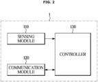
- FIG. 2 is a control block diagram of the electronic device 1, according to an embodiment.
- the electronic device 1 in an embodiment includes a sensing module 110 for detecting various types of operation data of the electronic device 1, a communication module 120 for performing wireless communication with the accessory 15, and a controller 130 for controlling the communication module 120 to perform wireless connection with the accessory 15 when the accessory 15 is coupled thereto and determining validity of the wireless connection.
- the control configuration of the electronic device 1 as shown in FIG. 2 is merely an example, and a component that is not shown in FIG. 2 may be added thereto or some of the components shown in FIG. 2 may be omitted.
- the sensing module 110 may detect coupling of the accessory 15.
- the coupling of the accessory may include a physical coupling of the accessory.
- the physical coupling may include structural connection, electrical connection and/or wired connection.
- the sensing module 110 may include at least one sensor.
- the sensing module 110 may include a current sensor for detecting a current applied to the accessory 15 or applied from the accessory 15, and detect coupling of the accessory 15 through detection of a current in a power line connected to the accessory 15.
- the controller 130 may determine coupling of the accessory 15 by receiving current data detected from the sensing module 110.
- the sensing module 110 may include a pressure sensor for detecting pressure applied by coupling of the accessory 15 or a voltage sensor for measuring a voltage at a voltage terminal connected by the coupling of the accessory 15.
- the type of the sensing module 110 for detecting coupling of the accessory 15 is not, however, limited to the above example, and there is no limitation on the type as long as it is a known type of coupling detection sensor.
- the sensing module 110 in an embodiment may detect an operation state of the electronic device 1.
- the sensing module 110 may include a pressure sensor for detecting a change in atmospheric pressure due to the performing of the dust discharge course.
- the communication module 120 may perform wireless communication with the accessory 15.
- the communication module 120 may be provided as a known type of wireless communication module, e.g., a Bluetooth low energy (BLE) communication module.
- BLE Bluetooth low energy
- the accessory 15 may also include a wireless communication module for wireless communication with the electronic device 1.
- the controller 130 may control the communication module 120 to pair with an accessory having the highest strength of an advertising signal among the plurality of accessories 15 of the same type as the type of the coupled accessory 15.
- the controller 130 may identify a type of the accessory 15 coupled to the electronic device 1.
- the controller 130 may control the communication module 120 to execute pairing according to an advertising signal having a highest strength among advertising signals outputted by the plurality of accessories 15 of the same type as the type of the coupled accessory 15
- controller 130 may control the communication module 120 to scan the advertising signal(s) when coupling of the accessory 15 is detected.
- the controller 130 may control the communication module 120 to transmit or receive state information to or from the accessory 15 when the accessory 15 is paired with.
- the state information of the accessory 15 may include at least one of a sensing information value or an operation setting value of the accessory 15.
- the state information of the electronic device 1 may include at least one of operation command information of the electronic device 1 or sensing information of the sensing module 110.
- the controller 130 may determine whether the paired accessory 15 corresponds to the coupled accessory 15 based on whether the state information received from the paired accessory 15 corresponds to the state information of the electronic device 1.
- the state information received from the paired accessory 15 may not correspond to the state information of the electronic device 1.
- the controller 130 may determine whether the paired battery 15a corresponds to the coupled battery 15a based on whether discharge state information received from the paired battery 15a corresponds to the operation command information of the electronic device 1 or sensing information of a discharge current of the coupled battery 15a.
- the controller 130 may determine whether the paired brush 15b corresponds to the coupled brush based on whether the state information received from the paired brush 15b corresponds to the operation command information of the electronic device 1 or sensing information of a current applied to the coupled brush 15b.
- the controller 130 may determine whether the paired docking station 15c and the coupled docking station 15c correspond to each other based on sensing information of the pressure sensor of the sensing module 110 corresponds to the performing of the dust discharge course.
- the controller 130 may determine whether the paired docking station 15c corresponds to the coupled docking station 15c based on whether the state information corresponds to the operation command information of the electronic device 1 or sensing information of a charge current of the coupled battery 15a.
- the controller 130 may release the pairing with the paired accessory 15 when the paired accessory 15 does not correspond to the coupled accessory 15.
- the controller 130 may restrict pairing with the paired accessory 15 and control the communication module 120 to pair with another accessory 15 based on strength of the advertising signal.
- the controller 130 may include at least one memory for storing a program for carrying out the aforementioned and following operations, and at least one processor for executing the program.
- the memory and the processor are each provided in the plural, they may be integrated in a single chip or physically distributed.
- FIG. 3 is a signal flowchart of the electronic device 1 pairing with the coupled accessory 15, according to an embodiment
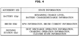
- FIG. 4 is a diagram for describing an example of state information transmitted or received by the electronic device 1 to or from the accessory 15, according to an embodiment.
- the electronic device 1 in an embodiment may start supplying power with an accessory 1 15-1 through a power line when the accessory 1 15-1 is coupled to the electronic device 1, in 301.
- the electronic device 1 may receive power from the accessory 1 15-1 through the power line.
- the electronic device 1 may supply power received from a battery to the accessory 1 15-1 through the power line.
- the electronic device 1 may detect coupling of the accessory 1 15-1, in 302. Specifically, the electronic device 1 may detect coupling of the accessory 1 15-1 based on the sensing information of the sensing module 110.
- the electronic device 1 may detect coupling of the accessory 1 15-1 to the electronic device 1 based on detection of a voltage or current in the power line connected to the accessory 1 15-1.
- the electronic device 1 may detect coupling of the accessory 1 15-1 to the electronic device 1 based on a change in pressure due to the coupling of the accessory 1 15-1.
- the electronic device 1 may scan an advertising signal in 303.
- the communication module 120 may scan the advertising signal transmitted from the accessory 15 when the accessory 1 15-1 is attached to.
- not only the accessory 1 15-1 coupled to the electronic device 1 but also an accessory 2 15-2 not coupled with the electronic device 1 may transmit the advertising signal, in 304.
- the accessory 2 15-2 may correspond to an extra accessory used for the electronic device 1 or an accessory used for other electronic device than the electronic device 1.
- the electronic device 1 may determine an accessory (e.g., accessory 1 15-1) having the highest signal strength (e.g., a receiver signal strength indicator (RSSI)) and send a request for pairing to the accessory 1 15-1 having the highest signal strength, in 306.
- an accessory e.g., accessory 1 15-1 having the highest signal strength (e.g., a receiver signal strength indicator (RSSI)) and send a request for pairing to the accessory 1 15-1 having the highest signal strength, in 306.
- RSSI receiver signal strength indicator
- the electronic device 1 may determine that the accessory 15 having the highest strength of the advertising signal corresponds to the coupled accessory 15 based on the fact that the nearer the physical distance the larger the advertising signal when the accessory 15 is coupled to the electronic device 1.
- the electronic device 1 may control the communication module 120 to pair with an accessory (accessory 1 15-1 in FIG. 3 ) having the highest strength of the advertising signal among the plurality of accessories 15-1 and 15-2 of the same type as the accessory 1 15-1 detected as being coupled to the electronic device 1.
- an accessory accessory 1 15-1 in FIG. 3
- the electronic device 1 may control the communication module 120 to pair with an accessory (accessory 1 15-1 in FIG. 3 ) having the highest strength of the advertising signal among the plurality of accessories 15-1 and 15-2 of the same type as the accessory 1 15-1 detected as being coupled to the electronic device 1.
- the electronic device 1 may determine a type of the coupled accessory 1 15-1 based on sensing information of the sensing module 110, determine a type of the accessories 15-1 and 15-2 that transmit the advertising signal based on packet information included in the advertising signal, and control the communication module 120 to pair with the accessory (the accessory 1 15-1 in FIG. 3 ) having the highest strength of the advertising signal among the plurality of accessories 15-1 and 15-2 of the same type as the type of the accessory 1 15-1 detected as being coupled to the electronic device 1.
- the number of accessories 15 from which the electronic device 1 receives the advertising signal may vary depending on the number of accessories 15 located around the electronic device 1.
- the electronic device 1 may exchange information with the accessory 1 15-1, in 307. Specifically, the electronic device 1 may control the communication module 120 to transmit or receive state information to or from the paired accessory 1 15-1.
- the state information of the accessory 15 may include at least one of an operation setting value of the accessory 15 or a sensing information value. Furthermore, the state information of the electronic device 1 may include at least one of operation command information of the electronic device 1 or sensing information of the sensing module 110.
- the state information of the battery 15a may include remaining charge level information, battery charge/discharge information, etc.
- the accessory 15 corresponds to the brush 15b revolutions per minute (rpm) information, brush current information, etc., may be included.
- rpm revolutions per minute
- state information of the docking station 15c may include dust discharge operation information, charging operation information, etc.
- the electronic device 1 may transmit its state information (cleaner state information) to the docking station 15c.
- the electronic device 1 may release the pairing with the accessory 1 15-1 in 309.
- the electronic device 1 may control the communication module 120 to release the pairing with the accessory 1 15-1 when detecting decoupling of the accessory 1 15-1 based on sensing information (e.g., a current or voltage in the power line) of the sensing module 110.
- sensing information e.g., a current or voltage in the power line
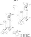
- FIG. 5 is a diagram for describing an occasion when the electronic device 1 makes a wrong connection with other accessory 15 than the coupled accessory 15, according to an embodiment.
- the electronic device 1 in the embodiment may correspond to a vacuum cleaner that performs cleaning by sucking up debris on the floor.
- the electronic device 1 may be coupled to the accessory 15.
- the electronic device 1 may be coupled to a battery 15a-1 for supplying power, a brush 15b-1 that comes into contact with the floor to perform cleaning, and a docking station 15c-1 for discharging debris collected in the dust collection bin of the electronic device 1 or charge the battery 15a-1.
- a battery 15a-1 for supplying power
- a brush 15b-1 that comes into contact with the floor to perform cleaning
- a docking station 15c-1 for discharging debris collected in the dust collection bin of the electronic device 1 or charge the battery 15a-1.
- accessories 15a-2 and 15b-2 allocated for the electronic device 1 around the electronic device 1, and there is another electronic device 2 different from the electronic device 1 and there may be accessories 15a-3, 15b-3 and 15c-3 that may be coupled to the other electronic device 2 around the electronic device 1.
- the electronic device 1 may happen to be paired with the accessory 15-2 or 15-3 instead of the coupled accessory 15-1 due to noise, communication fault or a change in location between the accessories.
- the electronic device 1 when the electronic device 1 is paired with the accessory 15-2 or 15-3 other than the coupled accessory 15-1, the electronic device 1 may fail to obtain state information from the coupled accessory 15-1 and may thus not perform an operation intended by the user.
- the electronic device 1 may determine whether the paired accessory 15 corresponds to the coupled accessory 15 based on whether the state information received from the paired accessory 15 corresponds to the state information of the electronic device 1 including at least one of the operation command information or the sensing information of the sensing module 110, to determine validity of the wireless connection with the paired accessory 15 and repeatedly attempt wireless connection with the coupled accessory 15 when wrong connection is made, thereby increasing accuracy in wireless connection.
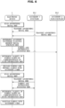
- FIG. 6 is a signal flowchart of the electronic device 1 determining validity of pairing with the accessory 15, according to an embodiment
- FIG. 7 illustrates an example of the electronic device 1 determining validity of pairing with the battery 15a
- FIG. 8 illustrates an example of the electronic device 1 determining validity of pairing with the brush 15b
- FIG. 9 illustrates an example of the electronic device 1 determining validity of pairing with the docking station 15c, according to an embodiment.
- the electronic device 1 in an embodiment may scan an advertising signal in 601, and the accessory 1 15-1 coupled to the electronic device 1 and the accessory 2 15-2 not coupled with the electronic device 1 may transmit the advertising signal in 602.
- the accessory 2 15-2 may not be coupled with the electronic device 1 in FIG. 6 and the following figures, embodiments of the disclosure are not limited thereto, and an accessory 3 15-3 coupled to the other electronic device 2 may also be included as one that transmits the advertising signal.
- the electronic device 1 may determine an accessory (the accessory 2 15-2) having the highest signal strength in 603, and pair with the accessory (the accessory 2 15-2) having the highest signal strength to exchange information in 604.
- the electronic device 1 may be wirelessly connected to the accessory 2 15-2 instead of the accessory 1 15-1, that is the coupled accessory 15, due to noise, communication error, positional relations between the accessories 15, etc.
- the electronic device 1 may determine validity of pairing based on correspondence of state information, in 605.
- the electronic device 1 may determine whether the paired accessory 15-2 corresponds to the coupled accessory 15-1 based on whether state information received from the paired accessory 15 corresponds to state information of the electronic device 1.
- the state information of the accessory 15-2 may include at least one of an operation setting value of the accessory 15-2 or a sensing information value. Furthermore, the state information of the electronic device 1 may include at least one of operation command information of the electronic device 1 or sensing information of the sensing module 110.
- the state information received from the paired accessory 15-2 may not correspond to the state information of the electronic device 1.
- the electronic device 1 may determine whether the paired battery 15a corresponds to the coupled battery 15a based on whether discharge state information received from the paired battery 15a corresponds to the operation command information of the electronic device 1 or sensing information of the sensing module 110.
- the electronic device 1 may be paired with other battery 15a-2 than the coupled battery 15a-1 and may receive state information from the other battery 15a-2.
- the electronic device 1 may determine whether the state information received from the other battery 15a-2 corresponds to the state information of the electronic device 1. For example, when the state information of the electronic device 1 indicates that cleaning is performed while the discharge state information received from the other battery 15a-2 does not indicate discharging of the current, the electronic device 1 may determine that the state information received from the other battery 15a-2 does not correspond to the state information of the electronic device 1, determine that the pairing with the other battery 15a-2 is not valid, and release and restrict the pairing with the other battery 15a-2.
- an operation command output by the controller 130 indicates that cleaning is to be performed (operation command information)
- a current or voltage of a suction motor is a current or voltage from an operation (sensing information of the sensing module 110)
- the state information received from the other battery 15a-2 indicates no discharging while the current or voltage of the coupled battery 15a indicates that the battery is being discharged
- the electronic device 1 may determine that the other battery 15a-2 does not correspond to the coupled battery 15a-1.
- the electronic device 1 may determine that the paired battery 15a-2 may not correspond to the coupled battery 15a-1.
- the electronic device 1 may determine whether the paired brush 15b corresponds to the coupled brush based on whether the state information received from the paired brush 15b corresponds to the operation command information of the electronic device 1 or sensing information of a current applied to the coupled brush 15b.
- the electronic device 1 may be paired with other brush 15b-2 than the coupled brush 15b-1 and may receive state information from the other battery 15b-2.
- the electronic device 1 may determine whether the state information received from the paired brush 15b-2 corresponds to the state information of the electronic device 1. For example, when the state information of the electronic device 1 indicates that cleaning is performed while the state information received from the paired brush 15b-2 does not indicate operation, the electronic device 1 may determine that the state information received from the paired brush 15b-2 does not correspond to the state information of the electronic device 1, determine that the pairing with the paired brush 15b-2 is not valid, and release and restrict the pairing with the paired brush 15b-2.
- the electronic device 1 may determine that the paired brush 15b-2 does not correspond to the coupled brush 15a-1.
- the electronic device 1 when the electronic device 1 is a vacuum cleaner, the coupled accessory 15 is a docking station 15c-1, and the state information received from a paired docking station 15c-2 indicates that a dust discharge course is being performed, the electronic device 1 may determine whether the paired docking station 15c-2 and the coupled docking station 15c-1 correspond to each other based on whether the sensing information of the pressure sensor of the sensing module 110 corresponds to the performing of the dust discharge course.
- the electronic device 1 may determine whether the paired docking station 15c-2 corresponds to the coupled docking station 15c-1 based on whether the state information received from the paired docking station 15c-2 corresponds to the sensing information of the pressure sensor of the sensing module 110 based on the fact that pressure changes in the vacuum cleaner according to the airflow sucked in at the docking station 15c when the dust discharge course is performed.
- the electronic device 1 may determine that the state information received from the paired docking station 15c-2 does not correspond to the sensing information of the pressure sensor of the sensing module 110, and determine that the paired docking station 15c-2 does not correspond to the coupled docking station 15c-1.
- the electronic device 1 may determine that the state information received from the paired docking station 15c-2 does not correspond to the sensing information of the pressure sensor of the sensing module 110, and determine that the paired docking station 15c-2 does not correspond to the coupled docking station 15c-1.
- the electronic device 1 may determine whether the paired docking station 15c-2 corresponds to the coupled docking station 15c-1 based on whether the state information corresponds to the operation command information of the electronic device 1 or sensing information of a charge current of the coupled battery 15a.
- the electronic device 1 may determine whether the paired docking station 15c-2 corresponds to the coupled docking station 15c-1 based on whether the state information received from the paired docking station 15c-2 corresponds to the sensing information of the charge current of the coupled battery 15a based on the fact that the current from the battery 15a changes when the battery charge course is performed by the docking station 15c.
- the electronic device 1 may determine that the state information received from the paired docking station 15c-2 does not correspond to the sensing information of the charge current of the coupled battery 15c and determine that the paired docking station 15c-2 does not correspond to the coupled docking station 15c-1.
- the electronic device 1 may determine that the state information received from the paired docking station 15c-2 does not correspond to the operation command information and determine that the paired docking station 15c-2 does not correspond to the coupled docking station 15c-1.
- the electronic device 1 when determining that the coupled accessory 1 15-1 and the paired accessory 2 15-2 do not correspond to each other, releases the pairing with the paired accessory 2 15-2 and restricts pairing with the accessory 2 15-2, in 606.
- the electronic device 1 may add the accessory 2 15-2 to a wrong connection list and restrict pairing with the accessory 2 15-2.
- the electronic device 1 may re-perform a course of scanning the advertising signal, in 607.
- the accessory 1 15-1 may transmit the advertising signal to the electronic device 1 in 608, and the electronic device 1 may be paired with the accessory 1 15-1 having the highest signal strength to exchange information in 609.
- the electronic device 1 may determine validity of the pairing based on correspondence of state information in 610, and maintain the pairing with the accessory 1 15-1 when determining that the coupled accessory 1 15-1 is the paired accessory 1 15-1, in 611.
- FIG. 10 is a flowchart of performing wireless connection with the accessory 15 in a method of controlling the electronic device 1, according to an embodiment.
- the electronic device 1 may control the communication module 120 to scan the advertising signal, in 1020.
- the electronic device 1 may detect coupling of the accessory 15 based on the sensing information of the sensing module 110, and control the communication module 120 to scan the advertising signal transmitted from the detected accessory 15.
- the electronic device 1 may identify the accessory 15 having the highest signal strength among a plurality of accessories of the same type as the coupled accessory 15 in 1030, and control the communication module 120 to pair with the identified accessory 15 in 1040.
- the electronic device 1 may determine that the accessory 15 having the highest strength of the advertising signal corresponds to the coupled accessory 15 based on the fact that the nearer the physical distance the larger the advertising signal when the accessory 15 is coupled to the electronic device 1.
- the electronic device 1 may determine a type of the coupled accessory 15 based on sensing information of the sensing module 110, determine a type of the accessory that transmits the advertising signal based on packet information included in the advertising signal, and control the communication module 120 to pair with the accessory 15 having the highest strength of the advertising signal among the plurality of accessories of the same type as the type of the accessory 15 detected as being coupled to the electronic device 1.
- the electronic device 1 may control the communication module 120 to transmit or receive state information to or from the paired accessory 1 15-1.
- the state information of the accessory 15 may include at least one of an operation setting value of the accessory 15 or a sensing information value. Furthermore, the state information of the electronic device 1 may include at least one of operation command information of the electronic device 1 or sensing information of the sensing module 110.
- the electronic device 1 may control the communication module 120 to release the pairing with the accessory 15, in 1070.
- the electronic device 1 may control the communication module 120 to release the pairing with the accessory 15 when detecting decoupling of the accessory 15 based on the sensing information (e.g., a current or voltage in the power line) of the sensing module 110.
- the sensing information e.g., a current or voltage in the power line
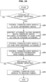
- FIG. 11 is a flowchart of determining validity of wireless connection with the accessory 15 in a method of controlling the electronic device 1, according to an embodiment.
- the electronic device 1 may identify the accessory 15 having the highest signal strength among the plurality of accessories 15 of the same type as the coupled accessory 15 in 1120, control the communication module 120 to pair with the identified accessory 15, in 1130, and control the communication module 120 to receive state information from the paired accessory 15 in 1140.
- the electronic device 1 may determine state information of the electronic device 1 including sensing information of the sensing module 110 or operation command information, in 1150.
- the electronic device 1 may determine state information of the electronic device 1 including at least one of sensing information or operation command information and indicating a state of the electronic device 1.
- the electronic device 1 may determine whether the state information received from the paired accessory 15 corresponds to the state information of the electronic device 1 in 1160, and in case of yes in 1170, maintain the pairing with the paired accessory 15 in 1180, and in case of no in 1170, release and restrict the pairing with the paired accessory 15 in 1190, and re-perform the pairing procedure in 1120 to 1190.
- the state information received from the paired accessory 15 may not correspond to the state information of the electronic device 1.
- the electronic device 1 may determine whether the paired accessory 15 corresponds to the coupled accessory 15 based on whether the state information received from the paired accessory 15 corresponds to the state information of the electronic device 1 including at least one of the operation command information or the sensing information of the sensing module 110, to determine validity of wireless connection with the paired accessory 15 and repeatedly attempt wireless connection with the coupled accessory 15 when a wrong connection is made, thereby increasing accuracy in wireless connection.
- the embodiments of the disclosure may be implemented in the form of a recording medium for storing instructions to be carried out by a computer.
- the instructions may be stored in the form of program codes, and when executed by a processor, may generate program modules to perform operations in the embodiments of the disclosure.
- the recording media may correspond to computer-readable recording media.
- the computer-readable recording medium includes any type of recording medium having data stored thereon that may be thereafter read by a computer.
- a computer may be a read only memory (ROM), a random access memory (RAM), a magnetic tape, a magnetic disk, a flash memory, an optical data storage device, etc.
Landscapes
- Engineering & Computer Science (AREA)
- Computer Networks & Wireless Communication (AREA)
- Signal Processing (AREA)
- Computer Security & Cryptography (AREA)
- Databases & Information Systems (AREA)
- Mechanical Engineering (AREA)
- Selective Calling Equipment (AREA)
- Charge And Discharge Circuits For Batteries Or The Like (AREA)
Applications Claiming Priority (2)
| Application Number | Priority Date | Filing Date | Title |
|---|---|---|---|
| KR1020220083400A KR20240006384A (ko) | 2022-07-06 | 2022-07-06 | 전자 장치 및 그 제어방법 |
| PCT/KR2023/005038 WO2024010184A1 (ko) | 2022-07-06 | 2023-04-13 | 전자 장치 및 그 제어방법 |
Publications (2)
| Publication Number | Publication Date |
|---|---|
| EP4460146A1 true EP4460146A1 (de) | 2024-11-06 |
| EP4460146A4 EP4460146A4 (de) | 2025-06-11 |
Family
ID=89453633
Family Applications (1)
| Application Number | Title | Priority Date | Filing Date |
|---|---|---|---|
| EP23835653.9A Pending EP4460146A4 (de) | 2022-07-06 | 2023-04-13 | Elektronische vorrichtung und steuerungsverfahren dafür |
Country Status (5)
| Country | Link |
|---|---|
| US (1) | US12581546B2 (de) |
| EP (1) | EP4460146A4 (de) |
| KR (1) | KR20240006384A (de) |
| CN (1) | CN118715865A (de) |
| WO (1) | WO2024010184A1 (de) |
Families Citing this family (1)
| Publication number | Priority date | Publication date | Assignee | Title |
|---|---|---|---|---|
| WO2026095404A1 (ko) * | 2024-10-29 | 2026-05-07 | 삼성전자주식회사 | 로봇 청소기 및 이의 제어 방법 |
Family Cites Families (24)
| Publication number | Priority date | Publication date | Assignee | Title |
|---|---|---|---|---|
| US8472874B2 (en) * | 2007-03-14 | 2013-06-25 | Apple Inc. | Method and system for pairing of wireless devices using physical presence |
| KR101851532B1 (ko) | 2011-11-23 | 2018-06-11 | 삼성전자주식회사 | 자동 페어링을 위한 단말 장치, 원격 제어 장치 및 방법 |
| JP6608286B2 (ja) * | 2012-12-20 | 2019-11-20 | コーニンクレッカ フィリップス エヌ ヴェ | プレッシャーサポート呼吸治療システム等のシステムにおける無線周辺機器の自動ペアリング |
| CN105981352B (zh) | 2014-02-05 | 2018-03-13 | 苹果公司 | 控制器、由控制器控制的附件和通信方法 |
| KR101640706B1 (ko) | 2015-01-28 | 2016-07-18 | 엘지전자 주식회사 | 진공 청소기 |
| US10304347B2 (en) | 2015-08-20 | 2019-05-28 | Apple Inc. | Exercised-based watch face and complications |
| US10733115B2 (en) * | 2016-01-29 | 2020-08-04 | Dell Products L.P. | Information handling system automated wireless pairing of peripheral devices |
| US10310725B2 (en) * | 2016-06-12 | 2019-06-04 | Apple Inc. | Generating scenes based on accessory state |
| JP2018174504A (ja) * | 2017-03-31 | 2018-11-08 | 富士通株式会社 | 接続制御装置、及び接続制御方法 |
| US10842334B2 (en) | 2018-05-04 | 2020-11-24 | Irobot Corporation | Filtering devices for evacuation stations |
| KR102475260B1 (ko) * | 2018-08-08 | 2022-12-07 | 삼성전자주식회사 | 전자 펜을 포함하는 전자 장치 및 그의 전자 펜과의 통신 연결 제어 방법 |
| KR102262165B1 (ko) | 2018-08-08 | 2021-06-09 | 삼성전자주식회사 | 입력 장치와의 통신 연결을 제어하는 전자 장치 및 그 제어 방법 |
| KR102557817B1 (ko) | 2018-09-04 | 2023-07-21 | 엘지전자 주식회사 | 무선 청소기 충전 거치대 및 그 충전 거치대의 제어 방법 |
| KR20200035734A (ko) | 2018-09-27 | 2020-04-06 | 엘지전자 주식회사 | 청소기 및 그것의 동작방법 |
| US10506650B1 (en) | 2018-11-19 | 2019-12-10 | Motorola Mobility Llc | Methods and systems for pairing electronic devices based upon proximity |
| KR102290760B1 (ko) | 2019-07-19 | 2021-08-18 | 엘지전자 주식회사 | 청소기의 제어 방법 |
| KR102291067B1 (ko) * | 2019-08-20 | 2021-08-18 | 엘지전자 주식회사 | 노즐 교체형 청소기 및 그 제어방법 |
| CN211243177U (zh) | 2019-09-21 | 2020-08-14 | 广东尚研电子科技有限公司 | 一种无线便携式吸尘器控制系统 |
| AU2020260510B2 (en) | 2019-11-06 | 2022-03-31 | Bissell Inc. | Surface cleaning apparatus |
| KR20210073058A (ko) | 2019-12-10 | 2021-06-18 | 엘지전자 주식회사 | 청소기의 제어 방법 |
| KR20210079940A (ko) | 2019-12-20 | 2021-06-30 | 엘지전자 주식회사 | 충전기 및 제어 방법 |
| KR20210112917A (ko) * | 2020-03-06 | 2021-09-15 | 엘지전자 주식회사 | 청소기 및 그 제어방법 |
| KR102253543B1 (ko) | 2020-08-14 | 2021-06-09 | 주식회사 케이에스티인텔리전스 | 지능형 전동 킥보드 안전 장치 |
| EP4254772A3 (de) | 2020-11-23 | 2023-12-06 | Hantover, Inc. | Drahtloses motorantriebssteuerungssystem für handmesser |
-
2022
- 2022-07-06 KR KR1020220083400A patent/KR20240006384A/ko active Pending
-
2023
- 2023-04-13 WO PCT/KR2023/005038 patent/WO2024010184A1/ko not_active Ceased
- 2023-04-13 CN CN202380021437.0A patent/CN118715865A/zh active Pending
- 2023-04-13 EP EP23835653.9A patent/EP4460146A4/de active Pending
- 2023-04-28 US US18/140,755 patent/US12581546B2/en active Active
Also Published As
| Publication number | Publication date |
|---|---|
| WO2024010184A1 (ko) | 2024-01-11 |
| EP4460146A4 (de) | 2025-06-11 |
| KR20240006384A (ko) | 2024-01-15 |
| CN118715865A (zh) | 2024-09-27 |
| US20240015803A1 (en) | 2024-01-11 |
| US12581546B2 (en) | 2026-03-17 |
Similar Documents
| Publication | Publication Date | Title |
|---|---|---|
| EP1457151B1 (de) | Automatisches Batterie-Ladesystem und Batterie-Lademethode eines Reinigungsroboters | |
| US11159064B2 (en) | Electronic device and method for transmission of reason wireless charging is stopping | |
| CN112189294B (zh) | 用于具有可充电电池的游戏装置的无线充电舱和充电舱架 | |
| CN110945742B (zh) | 将id分配给多个从管理模块的无线电池控制系统、方法和电池组 | |
| CN101719685B (zh) | 电动工具充电系统、电动工具电池组以及电动工具充电器 | |
| US9509171B2 (en) | Method and apparatus for optimizing standby power consumption and providing user indications in WPC based wireless charging system | |
| RU2350253C2 (ru) | Способ зарядки обслуживающего робота (варианты) | |
| US10581280B2 (en) | Power transmitting apparatus, control method for power transmitting apparatus, and recording medium storing program | |
| US20180342906A1 (en) | Wireless power transmitting unit, wireless power receiving unit, and control methods thereof | |
| US12581546B2 (en) | Electronic device and method for controlling the same | |
| SE523915C2 (sv) | Rengöringsrobotsystem med extern laddningsanordning och metod för dockning av laddningsanordning. | |
| CN113383479B (zh) | 用于对外部装置无线充电的电子装置 | |
| CN102692986B (zh) | 电子设备、连接设备、电子设备系统及方法 | |
| EP2602696A2 (de) | Verfahren und Vorrichtung zur Konfiguration von Berührungserfassungsparametern | |
| US20140266005A1 (en) | Accelerometer-based battery charge status indicator | |
| CN111546333A (zh) | 一种机器人及其自动控制方法和装置 | |
| US9152525B2 (en) | Serial communication device, serial communication system, and serial communication method | |
| CN107979122B (zh) | 电力接收装置、无线电力传输系统和电力接收方法 | |
| KR100899409B1 (ko) | 로봇청소기 장치 및 그에 따른 제어방법 | |
| WO2008002769A1 (en) | Mobile device with detachable accessory | |
| CN102332617B (zh) | 便携式终端及识别该便携式终端的电池的方法 | |
| CN109358238A (zh) | 一种天线防呆电路及装置 | |
| KR100758038B1 (ko) | 로봇청소기의 충전방법 | |
| CN114714946B (zh) | 一种无人充电装置及方法 | |
| CN111176277A (zh) | 移动电子设备自动对接方法、接驳装置、移动电子设备及存储介质 |
Legal Events
| Date | Code | Title | Description |
|---|---|---|---|
| STAA | Information on the status of an ep patent application or granted ep patent |
Free format text: STATUS: THE INTERNATIONAL PUBLICATION HAS BEEN MADE |
|
| PUAI | Public reference made under article 153(3) epc to a published international application that has entered the european phase |
Free format text: ORIGINAL CODE: 0009012 |
|
| STAA | Information on the status of an ep patent application or granted ep patent |
Free format text: STATUS: REQUEST FOR EXAMINATION WAS MADE |
|
| 17P | Request for examination filed |
Effective date: 20240731 |
|
| AK | Designated contracting states |
Kind code of ref document: A1 Designated state(s): AL AT BE BG CH CY CZ DE DK EE ES FI FR GB GR HR HU IE IS IT LI LT LU LV MC ME MK MT NL NO PL PT RO RS SE SI SK SM TR |
|
| REG | Reference to a national code |
Ref country code: DE Ref legal event code: R079 Free format text: PREVIOUS MAIN CLASS: H04W0076140000 Ipc: H04W0076100000 |
|
| A4 | Supplementary search report drawn up and despatched |
Effective date: 20250513 |
|
| RIC1 | Information provided on ipc code assigned before grant |
Ipc: H04W 76/14 20180101ALN20250507BHEP Ipc: H04W 76/30 20180101ALN20250507BHEP Ipc: A47L 9/28 20060101ALI20250507BHEP Ipc: H04W 8/00 20090101ALI20250507BHEP Ipc: H04W 48/16 20090101ALI20250507BHEP Ipc: H04W 4/02 20180101ALI20250507BHEP Ipc: H04W 4/80 20180101ALI20250507BHEP Ipc: H04W 12/50 20210101ALI20250507BHEP Ipc: H04W 24/08 20090101ALI20250507BHEP Ipc: H04W 76/10 20180101AFI20250507BHEP |
|
| DAV | Request for validation of the european patent (deleted) | ||
| DAX | Request for extension of the european patent (deleted) |