EP4459737A1 - Energiespeichersystem - Google Patents
Energiespeichersystem Download PDFInfo
- Publication number
- EP4459737A1 EP4459737A1 EP23799627.7A EP23799627A EP4459737A1 EP 4459737 A1 EP4459737 A1 EP 4459737A1 EP 23799627 A EP23799627 A EP 23799627A EP 4459737 A1 EP4459737 A1 EP 4459737A1
- Authority
- EP
- European Patent Office
- Prior art keywords
- fire fighting
- fighting water
- rack
- battery
- energy storage
- Prior art date
- Legal status (The legal status is an assumption and is not a legal conclusion. Google has not performed a legal analysis and makes no representation as to the accuracy of the status listed.)
- Pending
Links
Images


Classifications
-
- A—HUMAN NECESSITIES
- A62—LIFE-SAVING; FIRE-FIGHTING
- A62C—FIRE-FIGHTING
- A62C3/00—Fire prevention, containment or extinguishing specially adapted for particular objects or places
- A62C3/16—Fire prevention, containment or extinguishing specially adapted for particular objects or places in electrical installations, e.g. cableways
-
- H—ELECTRICITY
- H01—ELECTRIC ELEMENTS
- H01M—PROCESSES OR MEANS, e.g. BATTERIES, FOR THE DIRECT CONVERSION OF CHEMICAL ENERGY INTO ELECTRICAL ENERGY
- H01M50/00—Constructional details or processes of manufacture of the non-active parts of electrochemical cells other than fuel cells, e.g. hybrid cells
- H01M50/60—Arrangements or processes for filling or topping-up with liquids; Arrangements or processes for draining liquids from casings
- H01M50/691—Arrangements or processes for draining liquids from casings; Cleaning battery or cell casings
-
- A—HUMAN NECESSITIES
- A62—LIFE-SAVING; FIRE-FIGHTING
- A62C—FIRE-FIGHTING
- A62C35/00—Permanently-installed equipment
- A62C35/02—Permanently-installed equipment with containers for delivering the extinguishing substance
-
- A—HUMAN NECESSITIES
- A62—LIFE-SAVING; FIRE-FIGHTING
- A62C—FIRE-FIGHTING
- A62C35/00—Permanently-installed equipment
- A62C35/58—Pipe-line systems
- A62C35/60—Pipe-line systems wet, i.e. containing extinguishing material even when not in use
-
- A—HUMAN NECESSITIES
- A62—LIFE-SAVING; FIRE-FIGHTING
- A62C—FIRE-FIGHTING
- A62C35/00—Permanently-installed equipment
- A62C35/58—Pipe-line systems
- A62C35/68—Details, e.g. of pipes or valve systems
-
- H—ELECTRICITY
- H01—ELECTRIC ELEMENTS
- H01M—PROCESSES OR MEANS, e.g. BATTERIES, FOR THE DIRECT CONVERSION OF CHEMICAL ENERGY INTO ELECTRICAL ENERGY
- H01M10/00—Secondary cells; Manufacture thereof
- H01M10/42—Methods or arrangements for servicing or maintenance of secondary cells or secondary half-cells
- H01M10/4207—Methods or arrangements for servicing or maintenance of secondary cells or secondary half-cells for several batteries or cells simultaneously or sequentially
-
- H—ELECTRICITY
- H01—ELECTRIC ELEMENTS
- H01M—PROCESSES OR MEANS, e.g. BATTERIES, FOR THE DIRECT CONVERSION OF CHEMICAL ENERGY INTO ELECTRICAL ENERGY
- H01M10/00—Secondary cells; Manufacture thereof
- H01M10/60—Heating or cooling; Temperature control
- H01M10/65—Means for temperature control structurally associated with the cells
- H01M10/656—Means for temperature control structurally associated with the cells characterised by the type of heat-exchange fluid
- H01M10/6567—Liquids
- H01M10/6568—Liquids characterised by flow circuits, e.g. loops, located externally to the cells or cell casings
-
- H—ELECTRICITY
- H01—ELECTRIC ELEMENTS
- H01M—PROCESSES OR MEANS, e.g. BATTERIES, FOR THE DIRECT CONVERSION OF CHEMICAL ENERGY INTO ELECTRICAL ENERGY
- H01M50/00—Constructional details or processes of manufacture of the non-active parts of electrochemical cells other than fuel cells, e.g. hybrid cells
- H01M50/20—Mountings; Secondary casings or frames; Racks, modules or packs; Suspension devices; Shock absorbers; Transport or carrying devices; Holders
- H01M50/251—Mountings; Secondary casings or frames; Racks, modules or packs; Suspension devices; Shock absorbers; Transport or carrying devices; Holders specially adapted for stationary devices, e.g. power plant buffering or backup power supplies
-
- H—ELECTRICITY
- H01—ELECTRIC ELEMENTS
- H01M—PROCESSES OR MEANS, e.g. BATTERIES, FOR THE DIRECT CONVERSION OF CHEMICAL ENERGY INTO ELECTRICAL ENERGY
- H01M50/00—Constructional details or processes of manufacture of the non-active parts of electrochemical cells other than fuel cells, e.g. hybrid cells
- H01M50/60—Arrangements or processes for filling or topping-up with liquids; Arrangements or processes for draining liquids from casings
- H01M50/609—Arrangements or processes for filling with liquid, e.g. electrolytes
-
- H—ELECTRICITY
- H01—ELECTRIC ELEMENTS
- H01M—PROCESSES OR MEANS, e.g. BATTERIES, FOR THE DIRECT CONVERSION OF CHEMICAL ENERGY INTO ELECTRICAL ENERGY
- H01M50/00—Constructional details or processes of manufacture of the non-active parts of electrochemical cells other than fuel cells, e.g. hybrid cells
- H01M50/60—Arrangements or processes for filling or topping-up with liquids; Arrangements or processes for draining liquids from casings
- H01M50/673—Containers for storing liquids; Delivery conduits therefor
- H01M50/682—Containers for storing liquids; Delivery conduits therefor accommodated in battery or cell casings
-
- H—ELECTRICITY
- H01—ELECTRIC ELEMENTS
- H01M—PROCESSES OR MEANS, e.g. BATTERIES, FOR THE DIRECT CONVERSION OF CHEMICAL ENERGY INTO ELECTRICAL ENERGY
- H01M10/00—Secondary cells; Manufacture thereof
- H01M10/60—Heating or cooling; Temperature control
- H01M10/65—Means for temperature control structurally associated with the cells
- H01M10/655—Solid structures for heat exchange or heat conduction
- H01M10/6556—Solid parts with flow channel passages or pipes for heat exchange
- H01M10/6557—Solid parts with flow channel passages or pipes for heat exchange arranged between the cells
-
- H—ELECTRICITY
- H01—ELECTRIC ELEMENTS
- H01M—PROCESSES OR MEANS, e.g. BATTERIES, FOR THE DIRECT CONVERSION OF CHEMICAL ENERGY INTO ELECTRICAL ENERGY
- H01M2220/00—Batteries for particular applications
- H01M2220/10—Batteries in stationary systems, e.g. emergency power source in plant
-
- Y—GENERAL TAGGING OF NEW TECHNOLOGICAL DEVELOPMENTS; GENERAL TAGGING OF CROSS-SECTIONAL TECHNOLOGIES SPANNING OVER SEVERAL SECTIONS OF THE IPC; TECHNICAL SUBJECTS COVERED BY FORMER USPC CROSS-REFERENCE ART COLLECTIONS [XRACs] AND DIGESTS
- Y02—TECHNOLOGIES OR APPLICATIONS FOR MITIGATION OR ADAPTATION AGAINST CLIMATE CHANGE
- Y02E—REDUCTION OF GREENHOUSE GAS [GHG] EMISSIONS, RELATED TO ENERGY GENERATION, TRANSMISSION OR DISTRIBUTION
- Y02E60/00—Enabling technologies; Technologies with a potential or indirect contribution to GHG emissions mitigation
- Y02E60/10—Energy storage using batteries
Definitions
- the present disclosure relates to an energy storage system, and more particularly, to an energy storage system that enables the collection and disposal or recycling of a fire fighting water used to suppress fire.
- Secondary batteries widely used at present include lithium ion batteries, lithium polymer batteries, nickel cadmium batteries, nickel hydrogen batteries, nickel zinc batteries or the like.
- lithium secondary batteries have little or no memory effect, and thus they are gaining more attention than nickel-based secondary batteries for their advantages that recharging can be done whenever it is convenient, the self-discharge rate is very low and the energy density is high.
- lithium secondary batteries may be classified into can type secondary batteries in which an electrode assembly is included in a metal can and pouch type secondary batteries in which an electrode assembly is included in a pouch of an aluminum laminate sheet according to the shape of outer packaging.
- a secondary battery may be used alone, but in general, since the voltage of a secondary battery is about 2.5V to 4.5V, when a higher output voltage is required, a plurality of secondary batteries may be connected in series and/or in parallel to form a battery module. Additionally, a battery module may be used alone, or two or more battery modules may be electrically connected in series and/or in parallel to form a device of higher level such as a battery rack or a battery pack.
- an energy storage system including a plurality of battery racks to store power during off-peak hours and use the stored power during peak hours.
- an industrial energy storage system includes battery racks, each including a rack case and a plurality of battery modules which is received in the rack case along the vertical direction, an air conditioning device to manage the temperature of the battery racks and a container to provide a space accommodating the components.
- a fire extinguishing system is introduced into the energy storage system, the fire extinguishing system designed to, in the event of thermal runaway of battery cells in a specific battery module mounted in a battery rack, feed a fire fighting water into the specific battery module before heat propagation to the other battery modules in order to suppress the fire.
- a water tank in which a predetermined amount of fire fighting water is stored is disposed near the container to feed the fire fighting water into the container in the event of fire. Since the water tank cannot accommodate the fire fighting water more than the preset amount, when the fire fighting water goes out of the water tank in the event of fire, it is necessary to refill the water tank with the predetermined amount or more of fire fighting water. However, to fill the water tank with the fire fighting water, it is necessary to draw water from a source of water close to the energy storage system to the water tank or otherwise call a fire engine.
- the present disclosure is designed to solve the above-described problem, and therefore the present disclosure is directed to providing an energy storage system with a drain structure for easy collection and disposal of a fire fighting water used to suppress fire.
- the present disclosure is further directed to providing an energy storage system that enables the recycling of a fire fighting water used to suppress fire by collecting the used fire fighting water and refilling it in a water tank.
- An energy storage system includes at least one battery rack including a plurality of stacked battery modules; and a container accommodating the battery rack, and the container may include a bottom plate in which the battery rack is disposed; and a fire fighting water collection chamber disposed lower than the bottom plate and having at least one side in communication with the bottom plate to allow a fire fighting water dropped from the battery rack to enter.
- the bottom plate may include a rack installation region in which the battery rack is installed, and a drain region which is an open region to allow the fire fighting water to fall down, and the fire fighting water collection chamber is disposed vertically below the drain region, and the fire fighting water collection chamber may have an inclined bottom surface to direct the fire fighting water entering through the drain region toward a wall of the container.
- the energy storage system may include a valve unit coupled to the wall of the container to drain the fire fighting water collected in the fire fighting water collection chamber out of the container.
- the energy storage system may include a water level sensor disposed in the fire fighting water collection chamber, and the valve unit may be configured to be open/closed based on a signal from the water level sensor.
- the energy storage system may include a drain pump disposed in the fire fighting water collection chamber, and configured to operate based on the signal from the water level sensor.
- a plurality of the battery racks may be provided and arranged in N rows in the bottom plate.
- the drain region may be disposed in an area between the rows of the battery racks in the bottom plate or an area between a sidewall of the container and an outermost row of the battery racks.
- the drain region may be covered with a plate of a porous structure.
- the energy storage system may further include a water tank disposed outside of the container; a fire fighting water supply pipe connecting the water tank to the battery rack; and a fire fighting water collection pipe connecting the fire fighting water collection chamber to the water tank.
- a water level sensor and a drain pump may be disposed in the fire fighting water collection chamber, and the drain pump may be configured to operate so as to move the fire fighting water to the water tank through the fire fighting water collection pipe in response to detection of a water level in the fire fighting water collection chamber reaching a predetermined height by the water level sensor.
- the battery rack may include a plurality of battery modules; a rack case having receiving portions, each configured to insert and receive each of the plurality of battery modules at each predetermined height, and having a structure in which upper and lower sides and left and right sides are closed except front and rear sides; a rack connection pipe connected to each of the battery modules received in the receiving portions to supply the fire fighting water when a fire occurs; and a drain guide unit disposed on at least one surface of a front outer surface or a rear outer surface of the rack case, and configured to guide drainage of the fire fighting water to cause the fire fighting water coming out of the battery module after having been fed into the battery module to be dropped down to a location spaced a predetermined distance apart from the outer surface of the rack case.
- the drain guide unit may be coupled to the outer surface of the rack case at a location which is lower than an upper battery module of every two battery modules vertically adjacent to each other and higher than a lower battery module.
- the drain guide unit may protrude from the outer surface of the rack case with inclination of a predetermined angle to form an eave structure.
- the drain guide unit may be rotatably coupled to the outer surface of the rack case.
- the drain guide unit may be configured to form an eave structure for the underlying receiving portion when it is rotated downwards.
- the drain guide unit may include a drain guide plate of a plate shape hinged to the outer surface of the rack case; and a stopper configured to limit rotation of the drain guide plate so that the drain guide plate is at a preset angle with respect to the outer surface of the rack case.
- the energy storage system may further include a rack die which protrudes upwards from the bottom plate and supports the battery rack a predetermined height apart from the bottom plate; and a fence disposed around the rack die with a predetermined gap from the rack die, protruding upwards from the bottom plate and having at least one drain hole on a side.
- the energy storage system with the drain structure for easy collection and disposal of the fire fighting water used to suppress fire.
- the present disclosure it may be possible to collect the fire fighting water used to suppress fire and refill it in the water tank, thereby enabling the recycling of the fire fighting water. Accordingly, there is an effect as if the capacity of the water tank is enhanced.
- the battery racks for preventing flood damage of other adjacent battery module when feeding the fire fighting water into a target battery module (in which a thermal event occurred) to suppress fire.
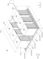
- FIG. 1 is a diagram schematically showing the architecture of an energy storage system according to an embodiment of the present disclosure
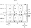
- FIG. 2 is a schematic plan view of the energy storage system according to an embodiment of the present disclosure
- FIG. 3 is a schematic cross-sectional view of the energy storage system according to an embodiment of the present disclosure
- FIG. 4 is a diagram showing a central area of a bottom plate of the container according to an embodiment of the present disclosure.
- the energy storage system 10 includes a container 100 and at least one battery rack 200 that may be received in the container 100.
- the container may include the bottom plate 120 in which the battery rack 200 is disposed and a fire fighting water collection chamber 130 disposed lower than the bottom plate 120 and having at least one side in communication with the bottom plate 120 to allow a fire fighting water dropped from the battery rack 200 to enter.
- the energy storage system 10 includes the fire fighting water collection chamber 130 in which the used fire fighting water (sewage) is directed toward one wall for collection and disposal, thereby achieving rapid disposal of the fire fighting water (sewage) after the fire situation ends.
- the battery rack 200 may include a plurality of stacked battery modules 210.
- Each battery module 210 may include a plurality of secondary batteries and a module housing 212 accommodating the secondary batteries. Additionally, each battery module 210 may be received in a rack case 220 and stacked in at least one direction. For example, each battery module 210 may be stacked in the vertical direction through the rack case 220.
- the plurality of battery racks 200 may be arranged along at least one direction in the container 100.
- the energy storage system 10 may include six battery racks 200 arranged in two rows, three in each row, within the container 100 as shown in FIG. 1 .
- the number of battery rack 200 included in the energy storage system 10 may be larger or smaller than six.
- the battery racks 200 may be arranged in three, four or more rows according to the size of the container 100 or the number of battery racks 200. That is, the battery racks 200 may be arranged in N rows (N is a natural number) in the bottom plate 120 within the container 100.
- the battery rack 200 may be configured to discharge the fire fighting water in the frontward or rearward direction of the rack case 220 after the fire fighting water is fed into the rack case 220 to suppress fire.
- the rack case 220 may be formed in a structure in which upper and lower ( ⁇ Z) sides and left and right ( ⁇ X) sides are closed and front and rear ( ⁇ Y) sides are open.
- the fire fighting water (sewage) used to suppress fire may be drained in the frontward or rearward direction of the rack case 220.
- the container 100 includes the bottom plate 120 in which the battery racks 200 are arranged, the fire fighting water collection chamber 130 disposed lower than the bottom plate 120 and walls surrounding the internal space.
- the walls include a first wall 111, a third wall 113 opposite the first wall 111 in parallel to each other, a second wall 112 crossing the first wall 111 and having two end portions connected to the first wall 111 and the third wall 113, and a fourth wall 114 opposite the second wall 112 in parallel to each other and having two end portions connected to the first wall 111 and the third wall 113.
- the container 100 is preferably made of a metal such as steel, and alternatively, may be in the form of a concrete structure.
- the bottom plate 120 may include a rack installation region 121 and a drain region 123.
- the rack installation region 121 refers to a region in which the battery racks 200 are installed
- the drain region 123 refers to an open region to allow the fire fighting water (sewage) to fall down from the bottom plate 120 and the fire fighting water collection chamber 130 is disposed vertically below the drain region 123.
- N rack installation regions 121 may be present, and the drain region 123 may be disposed in areas between the rows of the battery racks 200 arranged in the N rack installation regions 121 or areas between the sidewalls of the container 100 and the outermost rows of the battery racks 200.
- the rack installation regions 121 include a first rack installation region 121A and a second rack installation region 121B to arrange the battery racks 200 in two rows.
- the first rack installation region 121A and the second rack installation region 121B may be spaced a predetermined distance apart from each other (in Y direction).
- the three battery racks 200 may be arranged in the first rack installation region 121A along the X direction, and the three other battery racks 200 may be arranged in the second rack installation region 121B along the X direction, so the six battery racks 200 may be arranged in two rows, three in each row.
- each battery rack 200 may be arranged such that the drainage direction of the fire fighting water, that is, the front or rear side of the rack case faces the drain region 123. Additionally, each battery rack 200 may be connected to a fire fighting water supply pipe 400 to receive the fire fighting water in case of emergency. Additionally, the fire fighting water supply pipe 400 may be connected to a water tank 300 outside of the container 100.
- each battery rack 200 may be configured to receive the fire fighting water for fire suppression from the water tank 300 outside of the container 100 through the fire fighting water supply pipe 400, and drain the used fire fighting water in the frontward or rearward direction of the rack case 220.
- the drain region 123 may include a central drain region 123A at the center of the bottom plate 120 and a first side drain region 123B and a second side drain region 123C at two sides of the bottom plate 120.
- the central drain region 123A may be disposed in an area between the first rack installation region 121A and the second rack installation region 121B, in other words, an area between the battery racks 200 in the first row and the battery racks 200 in the second row. Additionally, the first side drain region 123B may be disposed in an area between the fourth wall 114 and the first rack installation region 121A, and the second side drain region 123C may be disposed in an area between the second wall 112 and the second rack installation region 121B.
- the fire fighting water used to suppress fire in the battery racks 200 in the first row may be drained from the battery racks 200 in the first row in +Y direction or -Y direction.
- the fire fighting water drained in -Y direction may flow into the central drain region 123A and the fire fighting water drained in +Y direction may flow into the first side drain region 123B.
- the fire fighting water used to suppress fire in the battery racks 200 in the second row may be drained from the battery racks 200 in the second row in +Y direction or -Y direction.
- the fire fighting water drained in +Y direction may flow into the central drain region 123A and the fire fighting water drained in -Y direction may flow into the second side drain region 123C.
- the drain region 123 may be covered with a plate C1 of a porous structure (see FIG. 1 ).
- the drain region 123 may be covered by a cover of a grating structure to allow an operator to move on the drain region 123, that is, the fire fighting water collection chamber 130.
- the fire fighting water collection chamber 130 may be a storage space disposed lower than the bottom plate 120 to temporarily store the fire fighting water (see FIG. 3 ).
- the fire fighting water may fall down from the drain region 123 and enter the fire fighting water collection chamber 130.
- the fire fighting water collection chamber 130 may have an inclined bottom surface 131 to direct the fire fighting water toward the wall of the container 100.
- the bottom surface 131 of the fire fighting water collection chamber 130 may be inclined in a way that it becomes lower from the third wall 113 to the first wall 111. In this case, as the fire fighting water moves along the inclined bottom surface 131, the fire fighting water is directed toward the first wall 111 of the container 100 in the fire fighting water collection chamber 130.
- the fire fighting water collection chamber 130 is disposed vertically below each of the central drain region 123, the first side drain region 123 and the second side drain region 123, corresponding to each drain region 123, and is connected to each other at the first wall 111. That is, the fire fighting water collection chamber 130 has a divided structure without a drainage path vertically below the first rack installation region 121 and the second rack installation region 121. This is to direct the fire fighting water toward the first wall 111 by making a drainage passage in which the fire fighting water moves below the bottom plate 120 narrow to cause the fire fighting water to move rapidly.
- the space below the bottom plate 120 may be formed as a space for collection of the fire fighting water by eliminating the divisions of the fire fighting water collection chamber 130 in order to enhance the storage capacity of the fire fighting water collection chamber 130.
- the battery rack 200 when the battery rack 200 is configured to drain the fire fighting water in a direction facing the central drain region 123A, the first side drain region 213B and the second side drain region 213C may be removed and accordingly the fire fighting water collection chamber 130 may be only disposed below the central drain region 123A.
- the fire fighting water may first move to the central drain region 123, fall down from the central drain region 123 and enter the fire fighting water collection chamber 130. Then, the fire fighting water entering the fire fighting water collection chamber 130 moves to the first wall 111 along the inclined bottom surface 131 of the fire fighting water collection chamber 130. As the fire fighting water is directed toward the first wall 111, the level of the fire fighting water increases toward the first wall 111.
- the degree of inclination of the fire fighting water collection chamber 130 indicated by J1 in FIG. 4 may be, for example, determined in a range between 5° and 60°, taking into account the length of the container 100 in X direction.
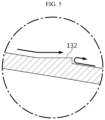
- a backflow prevention step 132 may be formed in the bottom surface 131 of the fire fighting water collection chamber 130. As shown in FIG. 5 , the backflow prevention step 132 may be formed at a predetermined interval along the inclined surface in the bottom surface 131 of the fire fighting water collection chamber 130 to prevent the backflow of the fire fighting water and prevent slips when the operator cleans the fire fighting water collection chamber 130.
- the energy storage system may further include a valve unit 140, a water level sensor 150 and a drain pump 160.
- the valve unit 140 refers to a mechanical device that shuts off the flow channel or controls the flow volume.
- the valve unit 140 may be a ball valve or a gate valve.
- the valve unit 140 may be connected to the fire fighting water collection chamber 130 through a drain tube which is installed outside of the wall of the container 100, that is, the first wall 111 in this embodiment, and passes through the first wall 111.
- the fire fighting water may be drained out of the container 100 by opening the valve unit 140.
- the level of the fire fighting water increase toward the first wall 111, and when the valve unit 140 is installed below the first wall 111 and the valve unit 140 is open, the fire fighting water may be smoothly discharged out of the container 100 by a level difference of the fire fighting water.
- the flow volume and the flow velocity of the fire fighting water flowing into the valve unit 140 decreases, and thus it may be difficult to completely drain the fire fighting water in the fire fighting water collection chamber 130 out of the container 100. Additionally, it is necessary to open the valve unit 140 before the fire fighting water collection chamber 130 is fully filled with the fire fighting water. Otherwise, the fire fighting water may flow over the bottom plate 120.
- the water level sensor 150 and the drain pump 160 may be used to solve this problem.
- the fire fighting water collection chamber 130 may be equipped with the water level sensor 150 to detect the level of the fire fighting water, and the valve unit 140 may be open/closed based on a signal from the water level sensor 150.
- the water level sensor 150 may be configured to transmit a signal for drainage to a valve control unit or generate an alarm sound.
- the valve unit 140 may be automatically opened by the valve control unit or manually opened by the operator who detected the alarm sound.
- the fire fighting water collection chamber 130 may be further equipped with the drain pump 160.
- the drain pump 160 may be configured to operate based on the signal from the water level sensor 150. For example, in the same way as the valve unit 140, when the preset water level is detected by the water level sensor 150, the signal of the water level sensor 150 may be transmitted to the drain pump 160 and the drain pump 160 may be switched on to cause the fire fighting water to move to the drain tube connected to the valve unit 140.
- the energy storage system 10 with the drain structure it may be possible to achieve easy collection and disposal of the fire fighting water (sewage) used to suppress fire, thereby reducing the time taken to re-operate the energy storage system 10 after the fire situation ends. Additionally, it may be possible to move the fire fighting water to a safe location through external pipe connected to the valve unit 140, or move the fire fighting water to the water tank 300 (having the reduced capacity since the fire fighting water came out of the water tank 300 to suppress fire), thereby enhancing the capacity of the water tank 300.
- the fire fighting water sewage
- the water tank 300 having the reduced capacity since the fire fighting water came out of the water tank 300 to suppress fire
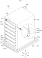
- FIG. 6 is a diagram showing the battery rack 200 according to an embodiment of the present disclosure before insertion of the battery module 210
- FIG. 7 is a diagram showing the battery rack 200 according to an embodiment of the present disclosure after insertion of the battery module 210
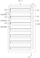
- FIG. 8 is a front view of the battery rack 200 of FIG. 7
- FIG. 9 is a diagram of the battery rack 200 of FIG. 7 when viewed from the rear side
- FIG. 10 is a rear view of the battery pack of FIG. 7 .
- the battery rack 200 may include the plurality of battery modules 210, the rack case 220, a rack connection pipe 230 and a drain guide unit 240.
- Each battery module 210 may include the secondary batteries 211 and the module housing 212 accommodating the secondary batteries 211 and may be configured to store and release electrical energy.
- the secondary batteries 211 may be connected in series and/or in parallel within the module housing 212 according to the required capacity and output for the battery module 210.
- each battery module 210 may include a cooling fan 214 and an air conditioning hole 216 to dissipate heat generated during charging/discharging.
- the cooling fan 214 may be disposed in the front surface portion of the module housing 212 and the air conditioning hole 216 may be disposed in the rear surface portion of the module housing 212.
- the cooling fan 214 operates, after the outside air enters the battery module 210 through the air conditioning hole 216 in the rear surface portion of the battery module 210 and absorbs heat of the secondary batteries 211, the air may be forced out through the cooling fan 214 in the front surface portion of the battery module 210.
- the cooling fan 214 may be disposed in the rear surface of the battery module 210 and the air conditioning hole 216 may be disposed in the front surface of the battery module 210.
- each battery module 210 may be configured to directly feed the fire fighting water into the module housing 212 in case of a situation in which a thermal event such as thermal runaway, fire, explosion or the like occurs in the secondary battery 211 during charging/discharging.
- the rack connection pipe 230 is connected to the rear surface of each battery module 210, and when a thermal event occurs, the fire fighting water may be fed into the corresponding battery module 210. Its detailed description will be provided below.
- the rack case 220 may be approximately cuboidal in shape to insert and receive each of the plurality of battery modules 210 at each predetermined height. Additionally, the rack case 220 may be made of a stiff material, preferably, a metallic or non-metallic material having high mechanical strength to protect the battery modules 210 from impacts or vibration.
- the rack case 220 may include a plurality of receiving portions 221 along the vertical direction and may be configured to receive each battery module 210 in each receiving portion 221.
- Each receiving portion 221 may have a structure in which the upper, lower, left and right sides (+Z,-Z,-X,+X) are closed except the front side (-Y) and the rear side (+Y).
- the rack case 220 is configured such that the upper, lower, left and right sides of each receiving portion 221 are closed and the front and rear sides are open to prevent flood damage of the other battery modules 210 and guide the drainage of the fire fighting water in the frontward or rearward direction when suppressing fire using the fire fighting water.
- the drain guide unit 240 may be disposed on at least one side of the front outer surface or the rear outer surface of the rack case 220 to cause the fire fighting water to be dropped down to a location spaced a predetermined distance apart from the outer surface of the rack case 220 when the fire fighting water coming out of the battery module 210 moves to the front side or rear side of the rack case 220 and falls out of the rack case 220.
- the drain guide unit 240 may protrude from the outer surface of the rack case 220 with inclination of a predetermined angle to form an eave structure.
- the eave refers to a portion that protrudes outwards on the basis of the outer surface of the rack case 220, and plays a role in protecting and covering the battery module 210 in the underlying receiving portion 221 from the fire fighting water falling down from above.
- the drain guide unit 240 may play a role in preventing venting gas to flames from the battery module 210 from spreading to the battery module 210 located on or below in the event of a fire in the battery module 210.
- the drain guide unit 240 may be coupled to the outer surface of the rack case 220 at a location that is lower than the upper battery module 210 of every two battery modules 210 vertically adjacent to each other and higher than the lower battery module 210. That is, the plurality of drain guide units 240 may be arranged along the vertical direction, and may be coupled to the outer surface of the rack case 220 at each height between the upper battery module 210 and the lower battery module 210.
- the battery rack 200 includes seven battery modules 210 stacked in the vertical direction, and in this case, six drain guide units 240 may be coupled to the front outer surface 220F of the rack case 220, and another six drain guide units 240 may be coupled to the rear outer surface 220R of the rack case 220. Then, when the fire fighting water is fed in response to a thermal event in any of the seven battery modules 210, the other battery modules 210 except the corresponding battery module 210 may avoid flood damage caused by the fire fighting water.
- the drain guide unit 240 is configured to partially cover the front side of a front open end of the underlying receiving portion 221.
- the battery module 210 when the battery module 210 while placed in horizontal condition is directly inserted into the receiving portion 221, the battery module 210 cannot be inserted into the receiving portion 221 due to interference with the drain guide unit 240.
- the eaves of the drain guide unit 240 may be short in length to avoid interference with the drain guide unit 240 when inserting the battery module 210 into the receiving portion 221.
- the eaves of the drain guide unit 240 is long in length to drain the fire fighting water by the drain guide unit 240 more effectively.
- the battery rack 200 includes the drain guide unit 240 of rotatable type.
- the drain guide unit 240 may be rotated and attached to the outer surface of the rack case 220.
- drain guide unit 240 may be configured to rotate in the upward direction to cover the receiving portion 221 located on the drain guide unit 240, and may be configured to rotate in the downward direction to form the eave structure for the underlying receiving portion 221 as shown in FIG. 7 .
- the battery module 210 when receiving the battery module 210 in the rack case 220, for example, in the condition shown in FIG. 6 , the battery module 210 may be first inserted into the bottommost receiving portion 221 and the drain guide unit 240 located immediately on the bottommost receiving portion 221 may rotate to form the eave structure. Then, the second receiving portion 221 from the bottommost side is open to allow the battery module 210 to be inserted into the receiving portion 221. In this instance, the second battery module 210 is inserted into the second receiving portion 221.
- the drain guide unit 240 may include a drain guide plate 241 and a stopper 242.
- the drain guide plate 241 may be in the shape of a plate that is hinged 243 to the outer surface of the rack case 220.
- the drain guide plate 241 may have a sufficient size to cover the receiving portion 221 located on the drain guide plate 241 when it is rotated upwards and attached to the outer surface of the rack case 220 and may be made of any stiff material, for example, plastics or metals.
- the drain guide plate 241 may have a magnet 244 in the opposite edge area to the hinged 243 edge area as shown in the enlarged diagram of FIG. 6 . The magnet 244 may be used to rotate the drain guide plate 241 upwards and fix it to the outer surface of the rack case 220.
- the eave structure is formed for rotating the drain guide plate 241 attached to the outer surface of the rack case 220 in the downward direction (-Z direction) to protect and partially cover the underlying receiving portion 221.
- the stopper 242 may be applied to limit the rotation of the drain guide plate 241 so that the drain guide plate 241 is at a preset angle ⁇ with respect to the outer surface of the rack case 220.
- the preset angle ⁇ may be, for example, determined in a range between 30° and 60°.
- the stopper 242 may be in the shape of a protrusion that protrudes from the edge area of the drain guide plate 241 close to the rotation axis so as to contact the outer surface of the rack case 220 at the preset angle ⁇ as shown in the enlarged section of FIG. 7 .
- the protrusion may be preferably in the shape of an approximately right-angled triangle in cross section and extended to a length corresponding to the horizontal ( ⁇ X direction) width of the drain guide plate 241.
- the drain guide plate 241 rotates in the downward direction, and stops when the hypotenuse of the right-angled triangle comes into contact with the outer surface of the rack case 220. Accordingly, the drain guide plate 241 may form the eave structure that protrudes with inclination of the preset angle with respect to the outer surface of the rack case 220.
- the drain guide unit 240 includes a first drain guide unit 240A on the front outer surface 220F of the rack case 220 as shown in FIG. 8 , and a second drain guide unit 240B on the rear outer surface 220R of the rack case 220 as shown in FIGS. 9 and 10 .
- the first drain guide unit 240A may have a sufficient size to cover the front open end of each receiving portion 221, and the second drain guide unit 240B may have a sufficient size to cover the rear open end of each receiving portion 221.
- the first drain guide unit 240A may have a sufficient size to cover the front open end of the receiving portion 221 when the first drain guide unit 240A is rotated in the upward direction (+Z direction) and attached to the front outer surface of the rack case 220 as shown in FIG. 6
- the second drain guide unit 240B may have a sufficient size to cover the rear open end of the receiving portion 221 when the second drain guide unit 240B is rotated in the upward direction (+Z direction) and attached to the rear outer surface of the rack case 220.
- the size of the first drain guide unit 240A and the size of the second drain guide unit 240B corresponding to them may be different.
- each receiving portion 221 of the rack case 220 has the narrower horizontal width ( ⁇ X direction) of the rear open end than the horizontal width of the front open end.
- the horizontal width of the rear open end of the receiving portion 221 has a width as much as 'L 1'.
- the rack connection pipe 230 is configured to supply the fire fighting water into each battery module 210 in case of emergency, and may have one side connected in communication with the fire fighting water supply pipe 400 and may be configured to pass through the rear outer surface of the rack case 220 and connect to the battery module 210 disposed in the receiving portion 221.
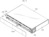
- the rack connection pipe 230 may include a main pipe 231 disposed in the vertical direction with respect to the rack case 220 and a plurality of connection nozzles 232 branching off from the main pipe 231 perpendicularly to the main pipe 231, and each connection nozzle 232 may be connected to a feed valve 217 disposed in the rear surface of the battery module 210 through the rear outer surface of the rack case 220.
- each connection nozzle 232 may be inserted into the rack case 220 through a through-hole (not shown) formed in the rear outer surface of the rack case 220.
- the battery module 210 may include the module housing 212, the secondary batteries 211 received in the module housing 212, the air conditioning hole 216 and the feed valve 217 in the rear surface of the module housing 212 and the cooling fan 214 in the front surface of the module housing 212.
- the cooling fan 214 may be disposed on the front side of the rack case 220 and the air conditioning hole 216 and the feed valve 217 may be disposed on the rear side of the rack case 220.
- the lower part of the air conditioning hole 216 may be closed by the rear outer surface of the rack case 220. That is, as indicated by 'K1' in FIG. 10 , the rack case 220 may have a wall that protrudes from the bottom surface of each receiving portion 221 at the rear open end of each receiving portion 221.
- the wall plays a role in preventing the fire fighting water from leaking through the rear side of the receiving portion 221.
- the wall is configured to guide the drain toward the front side of the rack case 220, but the wall may be omitted when guiding the drain toward the front side and the rear side of the rack case.
- the module housing 212 may be in the shape of an approximately cuboidal box having an internal space for receiving a cell stack formed by stacking the secondary batteries 211 in one direction, and including a bottom plate, a top plate, left and right side plates 212a, a front plate 213 and a rear plate 215.
- the six plates may be assemblable and disassemblable, but may be partially assemblable and disassemblable by integrally fabricating some of the six plates and individually fabricating the remaining plates.
- a pouch type secondary battery 211 may be used.
- the plurality of pouch type secondary batteries 211 is stacked in one direction to form the cell stack, and the cell stack is received in the module housing 212.
- the cell stack may be disposed in the module housing 212 such that the lengthwise direction of the pouch type secondary batteries 211 is perpendicular to the side plates 212a of the module housing 212.
- the cell stack when each direction perpendicular to the stack direction of the secondary batteries 211 is defined as a front surface direction and a rear surface direction of the cell stack, the cell stack may have the front surface portion and the rear surface portion facing the left and right side plates 212a at a predetermined gap between them respectively.
- the module housing 212 may have an air flow space and a space for placing a fire extinguishing unit 218.
- the fire extinguishing unit 218 may include a pipe shaped unit body 218a and a plurality of spray nozzles 218b as shown in FIG. 13 .
- the unit body 218a may be in the shape of a pipe having one end connected to the feed valve 217 and extended along the lengthwise direction of the module housing 212. Additionally, the plurality of spray nozzles 218b may be arranged at a predetermined interval along the lengthwise direction of the unit body 218a and may have outlets facing the cell stack.
- each spray nozzle 218b may include a glass bulb (not shown) configured to close the outlet through which jets of fire fighting water will be emitted in normal situation and open the outlet when thermal damage occurs.
- the glass bulb may be configured to receive a predetermined liquid or gas therein and break by volume expansion of the liquid or gas when it is heated.
- one end of the feed valve 217 may be connected to the connection nozzle 232 of the rack connection pipe 230, and inside of the rear plate 215, the other end of the feed valve 217, that is, the outlet to which the glass bulb is coupled may be disposed.
- the fire extinguishing unit 218 may be omitted from the inside of the module housing 212.
- the fire fighting water may be only fed into the battery module 210 in which the thermal event occurred among each battery module 210 included in the battery rack 200.
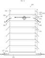
- the drainage mechanism of the fire fighting water after feeding the fire fighting water when a thermal event occurs in the battery module 210 will be described with reference to FIG. 14 below.
- the outlet of the spray nozzle 218b in the second battery module 210 is open. Then, by a pressure difference, the fire fighting water enters the battery module 210 through the feed valve 217 of the second battery module 210 from the rack connection pipe 230, moves along the unit body 218a and exits through the outlet of each spray nozzle 218b.
- the fire fighting water when the fire fighting water is directly fed into the second battery module 210 in which the thermal event occurs among the plurality of battery modules 210, it may be possible to suppress the fire situation or thermal runaway situation in the second battery module 210 more rapidly and effectively at the early stage. As a result, it may be possible to prevent thermal runaway or flame propagation to the other battery modules 210, and moreover, to prevent damage to the entire energy storage system 10 including the battery rack 200.
- the module housing 212 of the battery module 210 does not have a completely airtight structure. That is, the module housing 212 may have a gap due to the air conditioning hole 216 or the cooling fan 214 and an assembly clearance. Accordingly, the fire fighting water fed into the battery module 210 may leak out of the battery module 210 due to the above-described factors. When the fire fighting water leaking out of the battery module 210 flows into the other normal battery modules 210, it may cause serious flood damage to the corresponding battery modules 210.
- the battery rack 200 may be configured to receive each battery module 210 in the receiving portions 221 having a structure in which the upper and lower sides and the left and right sides are closed except the front and rear sides, in order to prevent flood damage to the other normal battery module 210.
- the fire fighting water is only drained in the frontward direction and the rearward direction of the rack case 220 as shown in FIG. 14 . Accordingly, the risk of flood damage of the other normal battery modules 210 is very low.
- the flow of the fire fighting water may be guided further outwards along the drain guide unit 240 to cause the fire fighting water to be dropped down to the location spaced the predetermined distance apart from the front outer surface or the rear outer surface of the rack case 220.
- the drain guide units 240 are vertically disposed in multistep arrangement along the heightwise direction of the rack case 220, and the drain guide units 240 disposed at lower positions protect each battery module 210 from the fire fighting water falling down from the height of the second battery module 210, thereby further reducing the flood damage risk of the other normal battery modules 210 below the second battery module 210.
- each battery rack 200 may be fixedly installed to the upper surface of a rack die 125 which protrudes upwards from the bottom plate 120 and supports the battery rack 200 a predetermined height apart from the bottom plate 120.
- the bottom plate 120 of the container 100 may have a fence 127 surrounding the rack die 125 with a predetermined gap from the rack die 125 and having at least one drain hole 127a.
- the fire fighting water when the fire fighting water falls down from the battery module, the fire fighting water may gather to the space between the rack die 125 and the fence 127, move along a slope formed between the rack die 125 and the fence 127 as indicated by F3 or F4 and go out of the fence 127 through the drain hole 127a.
- the flow may be guided to the central drain region 123A or the side drain regions 123B,123C of the bottom plate 120 (see FIGS. 1 and 4 ).
- the battery rack 200 may prevent the fire fighting water fed into the battery module 210 in which the thermal event occurred from entering the other adjacent battery modules 210.
- FIGS. 15 to 17 the energy storage system according to another embodiment of the present disclosure will be described with reference to FIGS. 15 to 17 .
- the same reference number as the above-described embodiment indicates the same element, and in the description of the same element, redundant description is omitted and difference(s) between this embodiment and the above-described embodiment will be described.
- the energy storage system 10 may include the container 100, at least one battery rack 200 received in the internal space of the container 100, and the water tank 300 connected to the battery rack 200 through the fire fighting water supply pipe 400 and configured to store the fire fighting water to be fed into the battery rack 200 in case of emergency.
- the container 100 includes the bottom plate 120 in which the battery rack 200 is disposed and the fire fighting water collection chamber 130 disposed lower than the bottom plate 120 and having at least one side in communication with the bottom plate 120 to allow the fire fighting water dropped from the battery rack 200 to enter.
- the energy storage system according to another embodiment of the present disclosure further includes a fire fighting water collection pipe 500 connecting the fire fighting water collection chamber 130 to the water tank 300.
- the fire fighting water used to suppress fire may be automatically collected and refilled in the water tank 300. Accordingly, after the fire situation ends, there is no need to clean or remove the used fire fighting water in the container 100 to re-operate the energy storage system 10, and since the fire fighting water coming out of the water tank 300 is refilled in the water tank 300 after collection, there is an effect as if the storage capacity of the water tank 300 is enhanced.
- the energy storage system 10 may include the water level sensor 150 and the drain pump 160.
- the water level sensor 150 and the drain pump 160 may be disposed in the fire fighting water collection chamber 130, and the drain pump 160 may be configured to operate when the water level in the fire fighting water collection chamber 130 reaching the predetermined height is detected by the water level sensor 150.
- the water level sensor 150 may be a level gauge or a float switch that outputs a signal when the height of the liquid surface reaches the predetermined level
- the drain pump 160 may be a submersible pump that works in water.
- the water level sensor 150 may output the signal, and in this instance, in response to the signal, the drain pump 160 may be switched on and start working to push the fire fighting water into the fire fighting water collection pipe 500.
- the fire fighting water collection pipe 500 is extended from the fire fighting water collection chamber 130 to the water tank 300 through one wall of the container 100, that is, the first wall 111. Accordingly, the fire fighting water may be fed into the water tank 300 through the fire fighting water collection pipe 500 by the operation of the drain pump 160. Meanwhile, the valve unit (not shown) that shuts off the flow channel or controls the flow volume such as a ball valve or a gate valve may be installed in the fire fighting water collection pipe 500 to shut off the flow of the fire fighting water or control the flow volume.
- the fire fighting water used to suppress fire is drained out of the container 100, it may be possible to reduce the time taken to re-operate the energy storage system 10 after the fire situation ends. Additionally, since the fire fighting water is collected and stored in the water tank 300 (having the reduced capacity since the fire fighting water came out of the water tank 300 to suppress fire) again, it may be possible to obtain the effect as if the storage capacity of the water tank 300 is enhanced.
- the energy storage system 10 may further include an air conditioning device to manage the temperature in the container 100, a Master Battery Management System to control all the battery racks 200 or the like.
Landscapes
- Chemical & Material Sciences (AREA)
- Chemical Kinetics & Catalysis (AREA)
- Electrochemistry (AREA)
- General Chemical & Material Sciences (AREA)
- Health & Medical Sciences (AREA)
- Public Health (AREA)
- Business, Economics & Management (AREA)
- Emergency Management (AREA)
- Engineering & Computer Science (AREA)
- Manufacturing & Machinery (AREA)
- Battery Mounting, Suspending (AREA)
Applications Claiming Priority (3)
| Application Number | Priority Date | Filing Date | Title |
|---|---|---|---|
| KR1020220054391A KR20230154680A (ko) | 2022-05-02 | 2022-05-02 | 소화수가 회수 및 순환될 수 있는 에너지 저장 시스템 |
| KR1020220054390A KR20230154679A (ko) | 2022-05-02 | 2022-05-02 | 소화수를 회수할 수 있는 에너지 저장 시스템 |
| PCT/KR2023/005825 WO2023214744A1 (ko) | 2022-05-02 | 2023-04-27 | 에너지 저장 시스템 |
Publications (2)
| Publication Number | Publication Date |
|---|---|
| EP4459737A1 true EP4459737A1 (de) | 2024-11-06 |
| EP4459737A4 EP4459737A4 (de) | 2025-08-20 |
Family
ID=88646650
Family Applications (1)
| Application Number | Title | Priority Date | Filing Date |
|---|---|---|---|
| EP23799627.7A Pending EP4459737A4 (de) | 2022-05-02 | 2023-04-27 | Energiespeichersystem |
Country Status (5)
| Country | Link |
|---|---|
| US (1) | US20250030141A1 (de) |
| EP (1) | EP4459737A4 (de) |
| JP (1) | JP2025503710A (de) |
| AU (1) | AU2023265721A1 (de) |
| WO (1) | WO2023214744A1 (de) |
Families Citing this family (2)
| Publication number | Priority date | Publication date | Assignee | Title |
|---|---|---|---|---|
| CN118173954B (zh) * | 2024-05-13 | 2025-11-11 | 晶科储能科技有限公司 | 一种储能装置 |
| CN120346476B (zh) * | 2025-06-18 | 2025-09-23 | 宁德时代新能源科技股份有限公司 | 储能系统及消防方法 |
Family Cites Families (12)
| Publication number | Priority date | Publication date | Assignee | Title |
|---|---|---|---|---|
| JPH02114977A (ja) * | 1988-10-25 | 1990-04-27 | Kawasaki Heavy Ind Ltd | 消防訓練方法及び消防訓練施設 |
| JP5976633B2 (ja) * | 2011-03-31 | 2016-08-23 | 三洋電機株式会社 | ラック型の電源装置 |
| KR20220054391A (ko) | 2019-08-29 | 2022-05-02 | 리서치 트라이앵글 인스티튜트 | 아펠린 수용체 작용제에 대한 방법 및 용도 |
| US12174010B2 (en) | 2019-10-03 | 2024-12-24 | Jfe Steel Corporation | In-mold solidified shell thickness estimation apparatus, in-mold solidified shell thickness estimation method, and continuous steel casting method |
| US11833377B2 (en) * | 2019-11-27 | 2023-12-05 | Saft America | Fire suppression system for battery modules |
| KR102307536B1 (ko) * | 2019-12-13 | 2021-09-30 | 정대원 | 배터리 에너지 저장시스템의 소화시스템 및 그 소화방법 |
| KR102742697B1 (ko) * | 2020-02-14 | 2024-12-13 | 주식회사 엘지에너지솔루션 | 전력 저장 시스템 |
| KR102650084B1 (ko) * | 2020-03-04 | 2024-03-20 | 주식회사 엘지에너지솔루션 | 배터리 랙 및 이러한 배터리 랙을 포함하는 전력 저장 장치 |
| KR102668862B1 (ko) * | 2020-03-04 | 2024-05-22 | 주식회사 엘지에너지솔루션 | 배터리 랙 및 그것을 포함하는 전력 저장 시스템 |
| KR102313994B1 (ko) * | 2020-04-28 | 2021-10-28 | 주식회사 에어퓨쳐 | 배터리 보관장치 및 배터리 보관실 |
| KR102390597B1 (ko) * | 2020-08-20 | 2022-04-27 | 이지에스주식회사 | Ess 전용 자동소화장치 |
| CN215341269U (zh) * | 2021-04-23 | 2021-12-28 | 深圳拓邦股份有限公司 | 一种具有消防装置的换电柜 |
-
2023
- 2023-04-27 JP JP2024542060A patent/JP2025503710A/ja active Pending
- 2023-04-27 AU AU2023265721A patent/AU2023265721A1/en active Pending
- 2023-04-27 EP EP23799627.7A patent/EP4459737A4/de active Pending
- 2023-04-27 WO PCT/KR2023/005825 patent/WO2023214744A1/ko not_active Ceased
- 2023-04-27 US US18/713,996 patent/US20250030141A1/en active Pending
Also Published As
| Publication number | Publication date |
|---|---|
| US20250030141A1 (en) | 2025-01-23 |
| AU2023265721A1 (en) | 2024-08-01 |
| EP4459737A4 (de) | 2025-08-20 |
| JP2025503710A (ja) | 2025-02-04 |
| WO2023214744A1 (ko) | 2023-11-09 |
Similar Documents
| Publication | Publication Date | Title |
|---|---|---|
| EP4459737A1 (de) | Energiespeichersystem | |
| EP4024590B1 (de) | Batteriemodul mit einer struktur zur verzögerung des löschwasserausflusses im brandfall und batteriesatz und energiespeichervorrichtung damit | |
| ES2998192T3 (en) | Battery rack and energy storage system comprising the same | |
| CN118414740A (zh) | 能量存储系统 | |
| JP7671852B2 (ja) | バッテリーラック及びこれを含むエネルギー貯蔵装置 | |
| KR20210109314A (ko) | 배터리 모듈, 및 그것을 포함하는 배터리 랙, 및 전력 저장 시스템 | |
| EP3091604B1 (de) | Batteriemodul und batteriepack damit | |
| JP7417764B2 (ja) | バッテリーラック、電力貯蔵装置、及び発電システム | |
| EP4456296A1 (de) | Batteriegestell mit drainagestruktur und energiespeichersystem damit | |
| KR20230105641A (ko) | 소화수 저장 탱크와 월 마운트 유닛을 구비한 배터리 팩 | |
| JP7602022B2 (ja) | バッテリーパックフレーム、それを含むバッテリーラック及び電力貯蔵装置 | |
| CN215680859U (zh) | 储能系统的储电模块和储能系统 | |
| CN221747431U (zh) | 防爆泄压储能装置 | |
| JP7617272B2 (ja) | バッテリーラック及びそれを含む電力貯蔵装置 | |
| KR20230154679A (ko) | 소화수를 회수할 수 있는 에너지 저장 시스템 | |
| KR20230100621A (ko) | 소화수 저장 탱크를 구비한 배터리 팩 | |
| CN223462372U (zh) | 一种能有效防止热失控扩散的电池模块及包含其的储能装置 | |
| CN219476889U (zh) | 一种电池模组及电池 | |
| EP4290679A1 (de) | Batteriepack mit verbesserter sicherheit | |
| CN118173954B (zh) | 一种储能装置 | |
| KR102858181B1 (ko) | 신속한 냉각이 가능한 구조를 갖는 배터리 모듈 및 이를 포함하는 ess | |
| KR20250156988A (ko) | 농업용 배터리 화재진압시스템 | |
| KR20250036622A (ko) | 배터리 팩 및 이를 포함하는 ess | |
| CN119495894A (zh) | 一种能有效防止热失控扩散的电池模块及其防护方法和储能装置 | |
| KR20230095799A (ko) | 안전성이 향상된 배터리 팩 |
Legal Events
| Date | Code | Title | Description |
|---|---|---|---|
| STAA | Information on the status of an ep patent application or granted ep patent |
Free format text: STATUS: THE INTERNATIONAL PUBLICATION HAS BEEN MADE |
|
| PUAI | Public reference made under article 153(3) epc to a published international application that has entered the european phase |
Free format text: ORIGINAL CODE: 0009012 |
|
| STAA | Information on the status of an ep patent application or granted ep patent |
Free format text: STATUS: REQUEST FOR EXAMINATION WAS MADE |
|
| 17P | Request for examination filed |
Effective date: 20240729 |
|
| AK | Designated contracting states |
Kind code of ref document: A1 Designated state(s): AL AT BE BG CH CY CZ DE DK EE ES FI FR GB GR HR HU IE IS IT LI LT LU LV MC ME MK MT NL NO PL PT RO RS SE SI SK SM TR |
|
| RIC1 | Information provided on ipc code assigned before grant |
Ipc: H01M 50/682 20210101ALI20250318BHEP Ipc: H01M 10/6568 20140101ALI20250318BHEP Ipc: A62C 99/00 20100101ALI20250318BHEP Ipc: A62C 35/68 20060101ALI20250318BHEP Ipc: A62C 35/02 20060101ALI20250318BHEP Ipc: A62C 3/16 20060101ALI20250318BHEP Ipc: H01M 10/48 20060101ALI20250318BHEP Ipc: H01M 50/251 20210101ALI20250318BHEP Ipc: H01M 10/42 20060101AFI20250318BHEP |
|
| DAV | Request for validation of the european patent (deleted) | ||
| DAX | Request for extension of the european patent (deleted) | ||
| A4 | Supplementary search report drawn up and despatched |
Effective date: 20250721 |
|
| RIC1 | Information provided on ipc code assigned before grant |
Ipc: H01M 10/42 20060101AFI20250715BHEP Ipc: H01M 50/251 20210101ALI20250715BHEP Ipc: H01M 10/48 20060101ALI20250715BHEP Ipc: A62C 3/16 20060101ALI20250715BHEP Ipc: A62C 35/02 20060101ALI20250715BHEP Ipc: A62C 35/68 20060101ALI20250715BHEP Ipc: A62C 99/00 20100101ALI20250715BHEP Ipc: H01M 10/6568 20140101ALI20250715BHEP Ipc: H01M 50/682 20210101ALI20250715BHEP |