EP4459701A2 - Silizium-clathrat-elektrodenaktivmaterial, negativelektrodenmischung, negativelektroden-aktivmaterialschicht, festkörper-lithium-ionen-batterie und verfahren zur herstellung einer negativelektroden-aktivmaterialschicht - Google Patents
Silizium-clathrat-elektrodenaktivmaterial, negativelektrodenmischung, negativelektroden-aktivmaterialschicht, festkörper-lithium-ionen-batterie und verfahren zur herstellung einer negativelektroden-aktivmaterialschicht Download PDFInfo
- Publication number
- EP4459701A2 EP4459701A2 EP24165285.8A EP24165285A EP4459701A2 EP 4459701 A2 EP4459701 A2 EP 4459701A2 EP 24165285 A EP24165285 A EP 24165285A EP 4459701 A2 EP4459701 A2 EP 4459701A2
- Authority
- EP
- European Patent Office
- Prior art keywords
- active material
- electrode active
- negative electrode
- silicon clathrate
- mass
- Prior art date
- Legal status (The legal status is an assumption and is not a legal conclusion. Google has not performed a legal analysis and makes no representation as to the accuracy of the status listed.)
- Pending
Links
Images
Classifications
-
- H—ELECTRICITY
- H01—ELECTRIC ELEMENTS
- H01M—PROCESSES OR MEANS, e.g. BATTERIES, FOR THE DIRECT CONVERSION OF CHEMICAL ENERGY INTO ELECTRICAL ENERGY
- H01M4/00—Electrodes
- H01M4/02—Electrodes composed of, or comprising, active material
- H01M4/36—Selection of substances as active materials, active masses, active liquids
- H01M4/38—Selection of substances as active materials, active masses, active liquids of elements or alloys
- H01M4/386—Silicon or alloys based on silicon
-
- H—ELECTRICITY
- H01—ELECTRIC ELEMENTS
- H01M—PROCESSES OR MEANS, e.g. BATTERIES, FOR THE DIRECT CONVERSION OF CHEMICAL ENERGY INTO ELECTRICAL ENERGY
- H01M10/00—Secondary cells; Manufacture thereof
- H01M10/05—Accumulators with non-aqueous electrolyte
- H01M10/052—Li-accumulators
- H01M10/0525—Rocking-chair batteries, i.e. batteries with lithium insertion or intercalation in both electrodes; Lithium-ion batteries
-
- H—ELECTRICITY
- H01—ELECTRIC ELEMENTS
- H01M—PROCESSES OR MEANS, e.g. BATTERIES, FOR THE DIRECT CONVERSION OF CHEMICAL ENERGY INTO ELECTRICAL ENERGY
- H01M10/00—Secondary cells; Manufacture thereof
- H01M10/05—Accumulators with non-aqueous electrolyte
- H01M10/056—Accumulators with non-aqueous electrolyte characterised by the materials used as electrolytes, e.g. mixed inorganic/organic electrolytes
- H01M10/0561—Accumulators with non-aqueous electrolyte characterised by the materials used as electrolytes, e.g. mixed inorganic/organic electrolytes the electrolyte being constituted of inorganic materials only
- H01M10/0562—Solid materials
-
- H—ELECTRICITY
- H01—ELECTRIC ELEMENTS
- H01M—PROCESSES OR MEANS, e.g. BATTERIES, FOR THE DIRECT CONVERSION OF CHEMICAL ENERGY INTO ELECTRICAL ENERGY
- H01M4/00—Electrodes
- H01M4/02—Electrodes composed of, or comprising, active material
- H01M4/04—Processes of manufacture in general
- H01M4/0471—Processes of manufacture in general involving thermal treatment, e.g. firing, sintering, backing particulate active material, thermal decomposition, pyrolysis
-
- H—ELECTRICITY
- H01—ELECTRIC ELEMENTS
- H01M—PROCESSES OR MEANS, e.g. BATTERIES, FOR THE DIRECT CONVERSION OF CHEMICAL ENERGY INTO ELECTRICAL ENERGY
- H01M4/00—Electrodes
- H01M4/02—Electrodes composed of, or comprising, active material
- H01M4/13—Electrodes for accumulators with non-aqueous electrolyte, e.g. for lithium-accumulators; Processes of manufacture thereof
- H01M4/134—Electrodes based on metals, Si or alloys
-
- H—ELECTRICITY
- H01—ELECTRIC ELEMENTS
- H01M—PROCESSES OR MEANS, e.g. BATTERIES, FOR THE DIRECT CONVERSION OF CHEMICAL ENERGY INTO ELECTRICAL ENERGY
- H01M4/00—Electrodes
- H01M4/02—Electrodes composed of, or comprising, active material
- H01M4/13—Electrodes for accumulators with non-aqueous electrolyte, e.g. for lithium-accumulators; Processes of manufacture thereof
- H01M4/139—Processes of manufacture
- H01M4/1395—Processes of manufacture of electrodes based on metals, Si or alloys
-
- H—ELECTRICITY
- H01—ELECTRIC ELEMENTS
- H01M—PROCESSES OR MEANS, e.g. BATTERIES, FOR THE DIRECT CONVERSION OF CHEMICAL ENERGY INTO ELECTRICAL ENERGY
- H01M4/00—Electrodes
- H01M4/02—Electrodes composed of, or comprising, active material
- H01M4/36—Selection of substances as active materials, active masses, active liquids
- H01M4/58—Selection of substances as active materials, active masses, active liquids of inorganic compounds other than oxides or hydroxides, e.g. sulfides, selenides, tellurides, halogenides or LiCoFy; of polyanionic structures, e.g. phosphates, silicates or borates
- H01M4/5825—Oxygenated metallic salts or polyanionic structures, e.g. borates, phosphates, silicates, olivines
-
- H—ELECTRICITY
- H01—ELECTRIC ELEMENTS
- H01M—PROCESSES OR MEANS, e.g. BATTERIES, FOR THE DIRECT CONVERSION OF CHEMICAL ENERGY INTO ELECTRICAL ENERGY
- H01M4/00—Electrodes
- H01M4/02—Electrodes composed of, or comprising, active material
- H01M2004/026—Electrodes composed of, or comprising, active material characterised by the polarity
- H01M2004/027—Negative electrodes
-
- H—ELECTRICITY
- H01—ELECTRIC ELEMENTS
- H01M—PROCESSES OR MEANS, e.g. BATTERIES, FOR THE DIRECT CONVERSION OF CHEMICAL ENERGY INTO ELECTRICAL ENERGY
- H01M2300/00—Electrolytes
- H01M2300/0017—Non-aqueous electrolytes
- H01M2300/0065—Solid electrolytes
- H01M2300/0068—Solid electrolytes inorganic
-
- Y—GENERAL TAGGING OF NEW TECHNOLOGICAL DEVELOPMENTS; GENERAL TAGGING OF CROSS-SECTIONAL TECHNOLOGIES SPANNING OVER SEVERAL SECTIONS OF THE IPC; TECHNICAL SUBJECTS COVERED BY FORMER USPC CROSS-REFERENCE ART COLLECTIONS [XRACs] AND DIGESTS
- Y02—TECHNOLOGIES OR APPLICATIONS FOR MITIGATION OR ADAPTATION AGAINST CLIMATE CHANGE
- Y02E—REDUCTION OF GREENHOUSE GAS [GHG] EMISSIONS, RELATED TO ENERGY GENERATION, TRANSMISSION OR DISTRIBUTION
- Y02E60/00—Enabling technologies; Technologies with a potential or indirect contribution to GHG emissions mitigation
- Y02E60/10—Energy storage using batteries
Definitions
- the present disclosure relates to a silicon clathrate electrode active material, a negative electrode mixture, a negative electrode active material layer, a solid-state lithium-ion battery, and a method for manufacturing a negative electrode active material layer.
- Silicon electrode active materials have a large theoretical capacity and are effective in high energy densification of batteries. However, silicon electrode active materials have a problem of large expansion during charging. On the other hand, it is known that using a silicon clathrate electrode active material as a silicon electrode active material suppresses expansion during charging.
- PTL 1 discloses a silicon clathrate electrode active material comprising a silicon clathrate type II crystal phase and having a composition of Na x Si 136 (1.98 ⁇ x ⁇ 2.54).
- silicon clathrate electrode active materials can suppress expansion during charging as compared to conventional silicon electrode active materials, there is a demand for further suppressing expansion of silicon clathrate electrode active materials during charging.
- An object of the present disclosure is to provide a silicon clathrate electrode active material having low expansion during charging and a solid-state lithium-ion battery comprising such a silicon clathrate electrode active material.
- a silicon clathrate electrode active material comprising a sodium compound, wherein a ratio of a mass of the sodium compound relative to a total mass of the silicon clathrate electrode active material and the sodium compound is 0.1% by mass or greater and 5.0% by mass or less.
- the silicon clathrate electrode active material according to any one of Aspects 1 to 3, at least partially having a clathrate type II structure.
- a negative electrode mixture comprising the silicon clathrate electrode active material according to any one of Aspects 1 to 4 and a solid electrolyte.
- a negative electrode active material layer containing the negative electrode mixture according to Aspect 5 or 6.
- a solid-state lithium-ion battery comprising the negative electrode active material layer according to Aspect 7.
- a silicon clathrate electrode active material having low expansion during charging and a solid-state lithium-ion battery comprising such a silicon clathrate electrode active material can be provided.
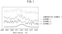
- FIG. 1 is a graph showing measurement results of bond energies of Examples 1 to 3 and Comparative Example 1 by X-ray photoelectron spectroscopy (XPS).
- the silicon clathrate electrode active material of the present disclosure comprises a sodium compound.
- a ratio of a mass of the sodium compound relative to a total mass of the silicon clathrate electrode active material and the sodium compound is 0.1% by mass or greater and 5.0% by mass or less.
- Silicon clathrate can be obtained by any method. Generally, silicon clathrate can be formed by removing sodium from a sodium-silicon (NaSi) alloy.
- silicon is first reacted with sodium hydride to prepare a NaSi alloy.
- the NaSi alloy prepared in such a manner is then heated to remove sodium from the NaSi alloy for clathratization, whereby silicon clathrate can be prepared.
- the NaSi alloy prepared in such a manner is reacted with aluminum fluoride as a sodium trapping agent to remove sodium from the NaSi alloy for clathratization, whereby silicon clathrate can be prepared.
- a sodium compound is generated in addition to silicon clathrate.
- the sodium compound can be removed by a subsequent treatment.
- the present disclosers have unexpectedly discovered that a silicon clathrate electrode active material containing low amount of sodium derived from a sodium compound has low expansion during charging.
- the reason therefor is presumed as follows. Specifically, it is considered that the small amount of sodium derived from the sodium compound can suppress oxidation reaction of the silicon clathrate electrode active material and reduction reaction of a solid electrolyte proceeding at an interface of the silicon clathrate electrode active material and the solid electrolyte, and as a result, a decrease in silicon clathrate electrode active material used in charging is suppressed and charging reactions proceed uniformly to suppress expansion during charging.
- electrode active material relating to the present disclosure can be used as a "positive electrode active material” or a “negative electrode active material”, and is used particularly as a "negative electrode active material”.
- the silicon clathrate electrode active material of the present disclosure comprises a sodium compound.
- the ratio of the mass of the sodium compound relative to the total mass of the silicon clathrate electrode active material and the sodium compound is 0.1% by mass or greater and less than 5.0% by mass. It is preferable that the ratio be within the above range in order to sufficiently suppress expansion during charging.
- the ratio may be 0.2% by mass or greater, 0.3% by mass or greater, 0.4% by mass or greater, 0.5% by mass or greater, 0.6% by mass or greater, 0.7% by mass or greater, or 0.8% by mass or greater, and may be 4.5% by mass or less, 4.0% by mass or less, 3.5% by mass or less, 3.3% by mass or less, 3.2% by mass or less, 3.1% by mass or less, 3.0% by mass or less, 2.9% by mass or less, or 2.8% by mass or less.
- the ratio can be calculated as a ratio of the area in the range of 1072 eV to 1076 eV relative to the area in the range of 1070 eV to 1076 eV from the X-ray photoelectron spectroscopy (XPS) measurement results of the silicon clathrate electrode active material.
- XPS X-ray photoelectron spectroscopy
- the sodium compound of the present disclosure may be sodium oxide and/or sodium silicate.
- the silicon clathrate electrode active material of the present disclosure can at least partially have a clathrate type II structure. In this case, expansion during charging can be further decreased.
- a treatment to remove oxide on the surface of the silicon clathrate electrode active material can be carried out in order to adjust the ratio of the mass of the sodium compound relative to the total mass of the silicon clathrate electrode active material and the sodium compound.
- the silicon clathrate electrode active material is immersed in a solution capable of dissolving and removing silicon oxide, for example, a hydrogen fluoride (HF) aqueous solution, and silicon oxide is dissolved and removed, whereby the sodium compound present on the surface of the silicon clathrate electrode active material can also be removed.
- a solution capable of dissolving and removing silicon oxide for example, a hydrogen fluoride (HF) aqueous solution
- HF hydrogen fluoride
- the silicon clathrate electrode active material has sodium silicate (Na 2 SiO 3 ) as the sodium compound, it is possible to convert sodium silicate to soluble silicic acid (H 2 SiO 3 ) using a hydrogen chloride aqueous solution (hydrochloric acid) and remove silicic acid to decrease sodium atoms in the silicon clathrate electrode active material (Na 2 SiO 3 + 2 HCl ⁇ 2 NaCl (dissolved) + H 2 SiO 3 (dissolved)).
- sodium silicate sodium silicate
- H 2 SiO 3 soluble silicic acid
- the oxide removal treatment can be accelerated.
- the silicon clathrate electrode active material can be placed in an oxidizing atmosphere and optionally heated.
- a method of placing in an oxidizing atmosphere a method of placing in an apparatus capable of depressurization and gas replacement, depressurizing the inside of the apparatus at room temperature, and then introducing atmospheric air is exemplified.
- an oxide film of silicon oxide (SiO 2 ) is formed on the surface of the silicon clathrate electrode active material, and when washed with HF, the sodium compound is washed away therewith.
- SiO 2 silicon oxide
- the degree of oxidation in the oxidation treatment is small, the generated amount of SiO 2 is small, and thus a decrease in the sodium compound is suppressed.
- the oxidation treatment is not carried out, there is little sodium compound generated, and thus the ratio of the mass of the sodium compound relative to the total mass of the silicon clathrate electrode active material and the sodium compound is decreased.
- an oxidation treatment be not carried out, or when an oxidation treatment is carried out, the amount of atmospheric air introduced be appropriately adjusted.
- the negative electrode mixture of the present disclosure comprises a silicon clathrate electrode active material as a negative electrode active material and a solid electrolyte.
- the negative electrode mixture of the present disclosure optionally comprises a conductive aid and a binder.
- the "negative electrode mixture” relating to the present disclosure means a composition that can constitute a negative active material layer as-is or by further containing additional components.
- the "negative electrode mixture slurry” relating to the present disclosure means a slurry that comprises a dispersion medium in addition to the "negative electrode mixture” and can thereby be applied and dried to form a negative electrode active material layer.
- the material of the solid electrolyte is not particularly limited, and any material usable as a solid electrolyte used in lithium-ion batteries can be used.
- the solid electrolyte may be a sulfide solid electrolyte, an oxide solid electrolyte, or a polymer electrolyte, and is preferably a sulfide solid electrolyte.
- the sulfide solid electrolyte examples include, but are not limited to, sulfide amorphous solid electrolytes, sulfide crystalline solid electrolytes, and argyrodite-type solid electrolytes.
- Specific examples of the sulfide solid electrolyte can include, but are not limited to, Li 2 S-P 2 S 5 -based (such as Li 7 P 3 S 11 , Li 3 PS 4 , and Li 8 P 2 S 9 ), Li 2 S-SiS 2 , LiI-Li 2 S-SiS 2 , LiI-Li 2 S-P 2 S 5 , LiI-LiBr-Li 2 S-P 2 S 5 , Li 2 S-P 2 S 5 -GeS 2 (such as Li 13 GeP 3 S 16 and Li 10 GeP 2 S 12 ), LiI-Li 2 S-P 2 O 5 , LiI-Li 3 PO 4 -P 2 S 5 , and Li 7-x PS 6-x Cl x
- oxide solid electrolyte examples include, but are not limited to, Li 7 La 3 Zr 2 O 12 , Li 7-x La 3 Zr 1-x Nb x O 12 , Li 7-3x La 3 Zr 2 Al x O 12 , Li 3x La 2/3-x TiO 3 , Li 1+x Al x Ti 2-x (PO 4 ) 3 , Li 1+x Al x Ge 2-x (PO 4 ) 3 , Li 3 PO 4 , and Li 3+x PO 4-x N x (LiPON).
- the sulfide solid electrolyte and the oxide solid electrolyte may be glass or crystallized glass (glass ceramics).
- polymer electrolyte examples include, but are not limited to, polyethylene oxide (PEO), polypropylene oxide (PPO), and copolymers thereof.
- the mass ratio (mass of silicon clathrate electrode active material : mass of solid electrolyte) of the silicon clathrate electrode active material to the solid electrolyte in the negative electrode mixture is preferably 85:15 to 30:70, and more preferably 80:20 to 40:60.
- the conductive aid is not particularly limited.
- the conductive aid may be, but is not limited to, a carbon material such as VGCF (vapor-grown carbon fiber), acetylene black (AB), ketjen black (KB), carbon nanotube (CNT), or carbon nanofiber (CNF); or a metal material.
- VGCF vapor-grown carbon fiber
- AB acetylene black
- KB ketjen black
- CNT carbon nanotube
- CNF carbon nanofiber
- the binder is not particularly limited.
- the binder may be of, but is not limited to, a material such as polyvinylidene fluoride (PVdF), butadiene rubber (BR), polytetrafluoroethylene (PTFE), or styrene-butadiene rubber (SBR), or a combination thereof.
- PVdF polyvinylidene fluoride
- BR butadiene rubber
- PTFE polytetrafluoroethylene
- SBR styrene-butadiene rubber
- the negative electrode active material layer of the present disclosure contains the negative electrode mixture of the present disclosure.
- the above descriptions relating to the negative electrode mixture of the present disclosure can be referenced regarding the negative electrode mixture.
- the thickness of the negative electrode active material layer may be, for example, 0.1 to 1000 ⁇ m.
- the method of the present disclosure for manufacturing a negative electrode active material layer comprises mixing the silicon clathrate electrode active material of the present disclosure, a solid electrolyte, and an organic solvent; and drying a slurry obtained by the mixing.
- organic solvent can include non-polar solvents such as heptane, xylene, and toluene; and polar solvents such as ester-based solvents, tertiary amine-based solvents, ether-based solvents, thiol-based solvents, and ketone-based solvents.
- the organic solvent is preferably a polar solvent, and more preferably a ketone-based solvent.
- the solid-state lithium-ion battery of the present disclosure comprises the negative electrode active material layer of the present disclosure.
- the solid-state lithium-ion battery of the present disclosure may comprise a negative electrode current collector layer, the negative electrode active material layer of the present disclosure, a solid electrolyte layer, a positive electrode active material layer, and a positive electrode current collector layer in this order.
- the lithium-ion battery of the present disclosure can be restrained by restraining members such as endplates from both sides in the laminating direction of the above layers.
- the "solid-state battery” relating to the present disclosure means a battery using at least a solid electrolyte as the electrolyte, and therefore the solid-state battery may use a combination of a solid electrolyte and a liquid electrolyte as the electrolyte.
- the solid-state battery of the present disclosure may be an all-solid-state battery, i.e., a battery using only a solid electrolyte as the electrolyte.
- the negative electrode active material layer contains the silicon clathrate electrode active material of the present disclosure, expansion associated with charging is decreased, thereby suppressing an increase in restraining pressure associated with charging.
- the material used in the negative electrode current collector layer is not particularly limited. Any material that can be used as a negative electrode current collector for batteries can be appropriately adopted.
- the material may be, but is not limited to, a stainless steel (SUS), aluminum, copper, nickel, iron, titanium, carbon, or resin current collector.
- the shape of the negative electrode current collector layer is not particularly limited. Examples thereof can include foil-like, plate-like, and mesh-like. Among these, a foil-like is preferable.
- the solid electrolyte layer comprises at least a solid electrolyte.
- the solid electrolyte layer may comprise a binder in addition to the solid electrolyte, as needed.
- the above descriptions relating to the negative electrode mixture of the present disclosure can be referenced regarding the solid electrolyte and the binder.
- the solid electrolyte layer may be impregnated with an electrolytic solution having lithium-ion conducting properties.
- the electrolytic solution preferably contains supporting salt of the electrolytic solution and a solvent.
- the supporting salt (lithium salt) of the electrolytic solution having lithium-ion conducting properties include inorganic lithium salts such as LiPF 6 , LiBF 4 , LiClO 4 , and LiAsF 6 ; and organic lithium salts such as LiCF 3 SO 3 , LiN(CF 3 SO 2 ) 2 , LiN(C 2 F 5 SO 2 ) 2 , LiN(FSO 2 ) 2 , and LiC(CF 3 SO 2 ) 3
- the solvent used in the electrolytic solution include cyclic esters (cyclic carbonates) such as ethylene carbonate (EC), propylene carbonate (PC), and butylene carbonate (BC); and chain esters (chain carbonates) such as dimethyl carbonate (DMC), diethyl carbonate (DEC), and ethyl methyl carbonate (EMC).
- the electrolytic solution preferably contains two or more solvents.
- the thickness of the solid electrolyte layer is, for example, 0.1 to 1000 ⁇ m.
- the thickness of the solid electrolyte layer is preferably 0.1 to 300 ⁇ m, and is further particularly preferably 0.1 to 100 ⁇ m.
- the positive electrode active material layer is a layer containing a positive electrode active material and optionally a solid electrolyte, a conductive aid, and a binder.
- the material of the positive electrode active material is not particularly limited.
- the positive electrode active material may be, but is not limited to, lithium cobaltate (LiCoO 2 ), lithium nickelate (LiNiO 2 ), lithium manganate (LiMn 2 O 4 ), LiCo 1/3 Ni 1/3 Mn 1/3 O 2 , or a heteroelement-substituted Li-Mn spinel having a composition represented by Li 1+x Mn 2-x-y M y O 4 (M is one or more metallic elements selected from Al, Mg, Co, Fe, Ni, and Zn).
- the positive electrode active material can comprise a covering layer.
- the covering layer is a layer containing a material that has lithium-ion conducting performance, has low reactivity with the positive electrode active material and the solid electrolyte, and can maintain the form of a covering layer that does not flow even when brought into contact with the active material or the solid electrolyte.
- Specific examples of the material constituting the covering layer can include, but are not limited to, Li 4 Ti 5 O 12 and Li 3 PO 4 , in addition to LiNbO 3 .
- the shape of the positive electrode active material examples include particulate.
- the average particle size (D50) of the positive electrode active material is not particularly limited, and is, for example, 10 nm or more, and may be 100 nm or more.
- the average particle size (D50) of the positive electrode active material is, for example, 50 ⁇ m or less, and may be 20 ⁇ m or less.
- the average particle size (D50) can be calculated from measurements with, for example, a laser diffraction particle size distribution analyzer or a scanning electron microscope (SEM).
- the mass ratio (mass of positive electrode active material : mass of solid electrolyte) of the positive electrode active material to the solid electrolyte in the positive electrode active material layer is preferably 85:15 to 30:70, and more preferably 80:20 to 40:60.
- the thickness of the positive electrode active material layer is, for example, 0.1 ⁇ m or more and 1000 ⁇ m or less.
- the material and shape used for the positive electrode current collector layer are not particularly limited, and the above descriptions relating to the negative electrode current collector layer of the present disclosure can be referenced therefor.
- the material of the positive electrode current collector layer is preferably aluminum, and the shape thereof is preferably foil-like.
- Si powder silicon (Si) source
- the obtained lithium-silicon alloy was reacted with ethanol in an argon atmosphere and further treated with hydrogen fluoride (HF) to
- the Si powder having a porous structure and sodium hydride (NaH) as a sodium (Na) source were used to manufacture a sodium-silicon (NaSi) alloy.
- NaH sodium hydride
- NaSi sodium-silicon
- the NaH and the Si powder having a porous structure were weighed at a molar ratio of 1.05: 1, and the weighed NaH and Si powder having a porous structure were mixed with a cutter mill. The obtained mixture was heated under the conditions of 500°C and 40 h in an argon atmosphere with a heating furnace to obtain a powdery NaSi alloy.
- the obtained NaSi alloy and aluminum fluoride (AlF 3 ) were weighed at a molar ratio of 1:0.35, and the weighed NaSi alloy and the AlF 3 were mixed with a cutter mill to obtain a reaction starting material.
- the obtained powdery reaction starting material was placed in a reaction vessel made of stainless steel and heated under the conditions of 310°C and 60 h in an argon atmosphere with a heating furnace to obtain a reaction product comprising silicon clathrate.
- the obtained reaction product was placed in an apparatus capable of depressurization and gas replacement, the inside of the apparatus was depressurized at room temperature, and atmospheric air was then introduced for oxidation.
- the oxidized reaction product was acid-washed using a mixed solvent of HNO 3 and H 2 O mixed at a volume ratio of 10:90 to remove by-products in the reaction product. After washing, the reaction product was filtered, and the filtered solid content was dried at 120°C for 3 h or more to obtain powdery silicon clathrate electrode active material. The obtained material was further washed with a 3-wt% HF solution, filtered, and then dried at 120°C for 3 h or more to obtain the silicon clathrate electrode active material of Comparative Example 1.
- Example 1 Except that the heating time for clathratization was set to 20 h and oxidation was not carried out, the silicon clathrate electrode active material of Example 1 was obtained in the same manner as in Comparative Example 1.
- Example 2 Except that oxidation for clathratization was not carried out, the silicon clathrate electrode active material of Example 2 was obtained in the same manner as in Comparative Example 1.
- the silicon clathrate electrode active material of each example comprised a clathrate type II crystal phase.
- a lithium-ion battery of each example was produced as follows.
- Ketone-based solvent a 5-wt% ketone-based solution of a polyvinylidene fluoride (PVDF)-based binder, vapor-grown carbon fiber (VGCF) as the conductive aid, the synthesized silicon clathrate electrode active material, and a Li 2 S-P 2 S 5 -based glass ceramic as the sulfide solid electrolyte were added to a polypropylene container and stirred with an ultrasonic dispersion apparatus (UH-50 manufactured by SMT) for 30 s. The container was then shaken with a shaker (TTM-1 manufactured by Sibata Scientific Technology Ltd.) for 30 min to obtain a slurry-like negative electrode mixture (negative electrode mixture slurry).
- PVDF polyvinylidene fluoride
- VGCF vapor-grown carbon fiber
- Li 2 S-P 2 S 5 -based glass ceramic as the sulfide solid electrolyte
- the obtained negative electrode mixture slurry was applied onto a copper (Cu) foil as a negative electrode current collector layer by a blade method using an applicator and dried for 30 min on a hot plate heated to 100°C to form a negative electrode active material layer on the negative electrode current collector layer.
- Cu copper
- Heptane, a 5-wt% heptane solution of a butadiene rubber (BR)-based binder and a Li 2 S-P 2 S 5 -based glass ceramic as the sulfide solid electrolyte were added to a polypropylene container and stirred with an ultrasonic dispersion apparatus (UH-50 manufactured by SMT) for 30 s.
- UH-50 manufactured by SMT ultrasonic dispersion apparatus
- the container was then shaken with a shaker (TTM-1 manufactured by Sibata Scientific Technology Ltd.) for 30 min to obtain a solid electrolyte slurry.
- the obtained solid electrolyte slurry was applied onto an aluminum (Al) foil as a release sheet by a blade method using an applicator and dried for 30 min on a hot plate heated to 100°C, whereby a solid electrolyte layer was formed. Three solid electrolyte layers were produced.
- ketone-based solvent a 5-wt% ketone-based solution of a PVDF-based binder, LiNi 1/3 Co 1/3 Mn 1/3 O 2 having an average particle size of 6 ⁇ m as the positive electrode active material, a Li 2 S-P 2 S 5 -based glass ceramic as the sulfide solid electrolyte, and VGCF as the conductive aid were added to a polypropylene container and stirred with an ultrasonic dispersion apparatus (UH-50 manufactured by SMT) for 30 s.
- UH-50 manufactured by SMT ultrasonic dispersion apparatus
- the container was then shaken with a shaker (TTM-1 manufactured by Sibata Scientific Technology Ltd.) for 3 min, further stirring was carried out with the ultrasonic dispersion apparatus for 30 s, and the container was shaken with the shaker for 3 min to obtain a positive electrode mixture slurry.
- a shaker TTM-1 manufactured by Sibata Scientific Technology Ltd.
- the obtained positive electrode mixture slurry was applied onto an Al foil as a positive electrode current collector layer by a blade method using an applicator and dried for 30 min on a hot plate heated to 100°C, whereby a positive electrode active material layer was formed on the positive electrode current collector layer.
- the positive electrode current collector layer, the positive electrode active material layer, and a first solid electrolyte layer were laminated in this order.
- the laminated product was set in a roll press machine and pressed at a pressing pressure of 100 kN/cm and a pressing temperature of 165 °C, whereby a positive electrode laminated body was obtained.
- the negative electrode current collector layer, the negative electrode active material layer, and a second solid electrolyte layer were laminated in this order.
- the laminated product was set in a roll press machine and pressed at a pressing pressure of 60 kN/cm and a pressing temperature of 25°C, whereby a negative electrode laminated body was obtained.
- the Al foil as a release sheet was peeled off from the solid electrolyte layer surface of each of the positive electrode laminated body and the negative electrode laminated body.
- the Al foil as a release sheet was then peeled off from a third solid electrolyte layer.
- the positive electrode laminated body and the negative electrode laminated body were set so that the solid electrolyte layer side of each thereof faces the third solid electrolyte layer and laminated to each other.
- the laminated body was set in a flat uniaxial press machine and temporarily pressed at 100 MPa and 25°C for 10 s.
- the laminated body was finally set in the flat uniaxial press machine and pressed at a pressing pressure of 200 MPa and a pressing temperature of 120°C for 1 min. As a result, an all-solid-state battery was obtained.
- XPS measurement was carried out on each of the silicon clathrate electrode active materials obtained in Comparative Example 1 and Examples 1 to 3 using an X-ray photoelectron spectrometer (ULVAC-PHI, Inc., VersaProbe II).
- the ratio of the mass of the sodium compound relative to the total mass of the silicon clathrate electrode active material and the sodium compound was calculated as a ratio of the area in the range of 1072 eV to 1076 eV relative to the area in the range of 1070 eV to 1076 eV from the XPS measurement results. From the obtained peaks, it was presumed that the sodium compound was at least one of sodium oxide and sodium silicate.
- the restraining pressure fluctuation of the all-solid-state battery of each example when restrained at a predetermined restraining pressure using a restraining jig and charged by constant current-constant voltage to 4.55 V at a 10-h rate (1/10 C) was measured.
- This restraining pressure fluctuation was defined as the expansion amount in the present disclosure. It should be noted that the restraining pressure fluctuation is the difference between the highest value and the lowest value in restraining pressure.
- the values of the Examples are shown as relative values when the value of Comparative Example 1 was set to 100.
- the ratio (mass fraction of sodium compound) of the mass of the sodium compound relative to the total mass of the silicon clathrate electrode active material and the sodium compound and the expansion amount of silicon clathrate electrode active material for each example are shown in Table 1.
- Table 1 Manufacturing conditions Results Firing time [h] Oxidation (relative value of amount of atmospheric air introduced) Mass fraction of Na compound [% by mass] Expansion amount (relative value) Comparative Example 1 60 100 0.01 100 Example 1 20 - 0.89 36.7 Example 2 60 - 1.05 16.7 Example 3 60 1 2.80 43.3
- the batteries of Examples 1 to 3 in which the ratio of the mass of the sodium compound relative to the total mass of the silicon clathrate electrode active material and the sodium compound was within the range of the present disclosure, had smaller expansion amounts than the battery of Comparative Example 1.
Landscapes
- Chemical & Material Sciences (AREA)
- Electrochemistry (AREA)
- General Chemical & Material Sciences (AREA)
- Chemical Kinetics & Catalysis (AREA)
- Engineering & Computer Science (AREA)
- Manufacturing & Machinery (AREA)
- Materials Engineering (AREA)
- Inorganic Chemistry (AREA)
- Physics & Mathematics (AREA)
- Condensed Matter Physics & Semiconductors (AREA)
- General Physics & Mathematics (AREA)
- Crystallography & Structural Chemistry (AREA)
- Battery Electrode And Active Subsutance (AREA)
- Secondary Cells (AREA)
- Silicon Compounds (AREA)
Applications Claiming Priority (1)
| Application Number | Priority Date | Filing Date | Title |
|---|---|---|---|
| JP2023075707A JP2024160567A (ja) | 2023-05-01 | 2023-05-01 | シリコンクラスレート電極活物質、負極合材、負極活物質層、固体リチウムイオン電池、及び負極活物質層の製造方法 |
Publications (2)
| Publication Number | Publication Date |
|---|---|
| EP4459701A2 true EP4459701A2 (de) | 2024-11-06 |
| EP4459701A3 EP4459701A3 (de) | 2025-03-12 |
Family
ID=90417498
Family Applications (1)
| Application Number | Title | Priority Date | Filing Date |
|---|---|---|---|
| EP24165285.8A Pending EP4459701A3 (de) | 2023-05-01 | 2024-03-21 | Silizium-clathrat-elektrodenaktivmaterial, negativelektrodenmischung, negativelektroden-aktivmaterialschicht, festkörper-lithium-ionen-batterie und verfahren zur herstellung einer negativelektroden-aktivmaterialschicht |
Country Status (5)
| Country | Link |
|---|---|
| US (1) | US20240372082A1 (de) |
| EP (1) | EP4459701A3 (de) |
| JP (1) | JP2024160567A (de) |
| KR (1) | KR102890513B1 (de) |
| CN (1) | CN118899402A (de) |
Families Citing this family (1)
| Publication number | Priority date | Publication date | Assignee | Title |
|---|---|---|---|---|
| JP7782511B2 (ja) * | 2023-05-16 | 2025-12-09 | トヨタ自動車株式会社 | シリコンクラスレート電極活物質の製造方法、及びリチウムイオン電池の製造方法 |
Citations (1)
| Publication number | Priority date | Publication date | Assignee | Title |
|---|---|---|---|---|
| JP2021158003A (ja) | 2020-03-27 | 2021-10-07 | トヨタ自動車株式会社 | 活物質、負極層、電池およびこれらの製造方法 |
Family Cites Families (5)
| Publication number | Priority date | Publication date | Assignee | Title |
|---|---|---|---|---|
| US9416013B2 (en) * | 2014-01-31 | 2016-08-16 | Colorado School Of Mines | Rapid reduction of sodium occupancy in type II silicon clathrate by chemical etching |
| JP7025383B2 (ja) * | 2019-08-27 | 2022-02-24 | 株式会社豊田自動織機 | シリコンクラスレートiiの製造方法 |
| JP6999619B2 (ja) * | 2019-08-27 | 2022-02-10 | 株式会社豊田自動織機 | シリコンクラスレートiiを含有する負極活物質 |
| JP2022034998A (ja) * | 2020-08-19 | 2022-03-04 | 株式会社豊田自動織機 | 負極活物質の製造方法 |
| JP7494800B2 (ja) * | 2021-06-04 | 2024-06-04 | トヨタ自動車株式会社 | ゲストフリーシリコンクラスレートの製造方法、ゲストフリーシリコンクラスレートの製造装置 |
-
2023
- 2023-05-01 JP JP2023075707A patent/JP2024160567A/ja active Pending
-
2024
- 2024-03-12 US US18/602,211 patent/US20240372082A1/en active Pending
- 2024-03-21 EP EP24165285.8A patent/EP4459701A3/de active Pending
- 2024-04-22 KR KR1020240053496A patent/KR102890513B1/ko active Active
- 2024-04-28 CN CN202410518393.9A patent/CN118899402A/zh active Pending
Patent Citations (1)
| Publication number | Priority date | Publication date | Assignee | Title |
|---|---|---|---|---|
| JP2021158003A (ja) | 2020-03-27 | 2021-10-07 | トヨタ自動車株式会社 | 活物質、負極層、電池およびこれらの製造方法 |
Also Published As
| Publication number | Publication date |
|---|---|
| KR20240160016A (ko) | 2024-11-08 |
| US20240372082A1 (en) | 2024-11-07 |
| KR102890513B1 (ko) | 2025-11-24 |
| EP4459701A3 (de) | 2025-03-12 |
| CN118899402A (zh) | 2024-11-05 |
| JP2024160567A (ja) | 2024-11-14 |
Similar Documents
| Publication | Publication Date | Title |
|---|---|---|
| EP1738425B1 (de) | Verfahren zur herstellung eines aktiven anodenmaterials mit verbesserten elektrochemischen eigenschaften | |
| EP3659976B1 (de) | Positives aktivmaterial für wiederaufladbare lithiumbatterie, verfahren zur herstellung davon und wiederaufladbare lithiumbatterie damit | |
| US20240014388A1 (en) | Negative electrode body, lithium ion battery, and method of producing active material for lithium ion battery | |
| EP4462507A1 (de) | Aktives material für silizium-clathrat-elektrode, negative elektrodenmischung, negative elektrodenaktivmaterialschicht und festkörper-lithium-ionen-batterie | |
| EP1959513B1 (de) | Aktives Verbundanodenmaterial, Herstellungsverfahren dafür sowie Anode und Lithiumbatterie mit dem Material | |
| JP2023167083A (ja) | 活物質、負極層、電池およびこれらの製造方法 | |
| US20240030421A1 (en) | Negative electrode active material particles, lithium ion battery, and method of producing negative electrode active material particles | |
| EP4459701A2 (de) | Silizium-clathrat-elektrodenaktivmaterial, negativelektrodenmischung, negativelektroden-aktivmaterialschicht, festkörper-lithium-ionen-batterie und verfahren zur herstellung einer negativelektroden-aktivmaterialschicht | |
| JP2024011899A (ja) | 負極活物質、負極活物質層、及びリチウムイオン電池、並びに負極活物質の製造方法 | |
| EP4443542A2 (de) | Negativelektroden-aktivmaterialschicht und festkörpersekundärbatterie | |
| KR102931098B1 (ko) | 황화철의 제조방법 | |
| EP4459702A1 (de) | Elektrodenmischung und lithium-ionen-batterie | |
| JP7622811B1 (ja) | 電極活物質、電極合材、電極層、電池、および、これらの製造方法 | |
| EP4687182A1 (de) | Elektrodenschicht und batterie | |
| EP4475222A1 (de) | Aktivmaterial für lithium-ionen-batterien und lithium-ionen-batterie | |
| US20260005235A1 (en) | Electrode active material and battery | |
| US20240343590A1 (en) | Method for manufacturing silicon clathrate active material, and method for manufacturing lithium ion battery | |
| US20240387808A1 (en) | Method for manufacturing silicon clathrate electrode active material, and method for manufacturing lithium-ion battery | |
| KR20260017966A (ko) | 전극층 및 전지 | |
| WO2025069757A1 (ja) | 電極活物質、電極合材、電池、および、これらの製造方法 | |
| US20240387809A1 (en) | Method for manufacturing silicon clathrate electrode active material, and method for manufacturing lithium-ion battery | |
| KR20260017965A (ko) | 전극층 및 전지 | |
| CN120237182A (zh) | 电极活性物质、电极合剂、电池和它们的制造方法 | |
| CN121127985A (zh) | 覆盖活性物质、覆盖活性物质的制造方法、正极材料以及电池 |
Legal Events
| Date | Code | Title | Description |
|---|---|---|---|
| PUAI | Public reference made under article 153(3) epc to a published international application that has entered the european phase |
Free format text: ORIGINAL CODE: 0009012 |
|
| STAA | Information on the status of an ep patent application or granted ep patent |
Free format text: STATUS: REQUEST FOR EXAMINATION WAS MADE |
|
| 17P | Request for examination filed |
Effective date: 20240331 |
|
| AK | Designated contracting states |
Kind code of ref document: A2 Designated state(s): AL AT BE BG CH CY CZ DE DK EE ES FI FR GB GR HR HU IE IS IT LI LT LU LV MC ME MK MT NL NO PL PT RO RS SE SI SK SM TR |
|
| PUAL | Search report despatched |
Free format text: ORIGINAL CODE: 0009013 |
|
| AK | Designated contracting states |
Kind code of ref document: A3 Designated state(s): AL AT BE BG CH CY CZ DE DK EE ES FI FR GB GR HR HU IE IS IT LI LT LU LV MC ME MK MT NL NO PL PT RO RS SE SI SK SM TR |
|
| RIC1 | Information provided on ipc code assigned before grant |
Ipc: H01M 4/02 20060101ALN20250206BHEP Ipc: H01M 4/58 20100101ALI20250206BHEP Ipc: H01M 4/38 20060101ALI20250206BHEP Ipc: C01B 33/00 20060101ALI20250206BHEP Ipc: H01M 10/0562 20100101ALI20250206BHEP Ipc: H01M 10/0525 20100101ALI20250206BHEP Ipc: H01M 4/1395 20100101ALI20250206BHEP Ipc: H01M 4/134 20100101AFI20250206BHEP |