EP4459401A1 - Verfahren und vorrichtung zum testen einer multi-ecu-simulation, computervorrichtung und speichermedium - Google Patents
Verfahren und vorrichtung zum testen einer multi-ecu-simulation, computervorrichtung und speichermedium Download PDFInfo
- Publication number
- EP4459401A1 EP4459401A1 EP22914467.0A EP22914467A EP4459401A1 EP 4459401 A1 EP4459401 A1 EP 4459401A1 EP 22914467 A EP22914467 A EP 22914467A EP 4459401 A1 EP4459401 A1 EP 4459401A1
- Authority
- EP
- European Patent Office
- Prior art keywords
- ecu
- simulated
- target
- application
- simulation
- Prior art date
- Legal status (The legal status is an assumption and is not a legal conclusion. Google has not performed a legal analysis and makes no representation as to the accuracy of the status listed.)
- Pending
Links
Images


Classifications
-
- G—PHYSICS
- G05—CONTROLLING; REGULATING
- G05B—CONTROL OR REGULATING SYSTEMS IN GENERAL; FUNCTIONAL ELEMENTS OF SUCH SYSTEMS; MONITORING OR TESTING ARRANGEMENTS FOR SUCH SYSTEMS OR ELEMENTS
- G05B17/00—Systems involving the use of models or simulators of said systems
- G05B17/02—Systems involving the use of models or simulators of said systems electric
-
- G—PHYSICS
- G05—CONTROLLING; REGULATING
- G05B—CONTROL OR REGULATING SYSTEMS IN GENERAL; FUNCTIONAL ELEMENTS OF SUCH SYSTEMS; MONITORING OR TESTING ARRANGEMENTS FOR SUCH SYSTEMS OR ELEMENTS
- G05B23/00—Testing or monitoring of control systems or parts thereof
- G05B23/02—Electric testing or monitoring
- G05B23/0205—Electric testing or monitoring by means of a monitoring system capable of detecting and responding to faults
- G05B23/0208—Electric testing or monitoring by means of a monitoring system capable of detecting and responding to faults characterized by the configuration of the monitoring system
- G05B23/0213—Modular or universal configuration of the monitoring system, e.g. monitoring system having modules that may be combined to build monitoring program; monitoring system that can be applied to legacy systems; adaptable monitoring system; using different communication protocols
-
- G—PHYSICS
- G06—COMPUTING OR CALCULATING; COUNTING
- G06F—ELECTRIC DIGITAL DATA PROCESSING
- G06F11/00—Error detection; Error correction; Monitoring
- G06F11/22—Detection or location of defective computer hardware by testing during standby operation or during idle time, e.g. start-up testing
- G06F11/2205—Detection or location of defective computer hardware by testing during standby operation or during idle time, e.g. start-up testing using arrangements specific to the hardware being tested
- G06F11/2236—Detection or location of defective computer hardware by testing during standby operation or during idle time, e.g. start-up testing using arrangements specific to the hardware being tested to test CPU or processors
-
- G—PHYSICS
- G06—COMPUTING OR CALCULATING; COUNTING
- G06F—ELECTRIC DIGITAL DATA PROCESSING
- G06F11/00—Error detection; Error correction; Monitoring
- G06F11/22—Detection or location of defective computer hardware by testing during standby operation or during idle time, e.g. start-up testing
- G06F11/2273—Test methods
-
- G—PHYSICS
- G06—COMPUTING OR CALCULATING; COUNTING
- G06F—ELECTRIC DIGITAL DATA PROCESSING
- G06F11/00—Error detection; Error correction; Monitoring
- G06F11/30—Monitoring
- G06F11/34—Recording or statistical evaluation of computer activity, e.g. of down time, of input/output operation ; Recording or statistical evaluation of user activity, e.g. usability assessment
- G06F11/3457—Performance evaluation by simulation
-
- G—PHYSICS
- G06—COMPUTING OR CALCULATING; COUNTING
- G06F—ELECTRIC DIGITAL DATA PROCESSING
- G06F11/00—Error detection; Error correction; Monitoring
- G06F11/36—Prevention of errors by analysis, debugging or testing of software
- G06F11/3668—Testing of software
- G06F11/3672—Test management
- G06F11/3688—Test management for test execution, e.g. scheduling of test suites
-
- G—PHYSICS
- G06—COMPUTING OR CALCULATING; COUNTING
- G06F—ELECTRIC DIGITAL DATA PROCESSING
- G06F11/00—Error detection; Error correction; Monitoring
- G06F11/36—Prevention of errors by analysis, debugging or testing of software
- G06F11/3698—Environments for analysis, debugging or testing of software
-
- G—PHYSICS
- G06—COMPUTING OR CALCULATING; COUNTING
- G06F—ELECTRIC DIGITAL DATA PROCESSING
- G06F30/00—Computer-aided design [CAD]
- G06F30/10—Geometric CAD
- G06F30/15—Vehicle, aircraft or watercraft design
-
- G—PHYSICS
- G06—COMPUTING OR CALCULATING; COUNTING
- G06F—ELECTRIC DIGITAL DATA PROCESSING
- G06F30/00—Computer-aided design [CAD]
- G06F30/20—Design optimisation, verification or simulation
-
- H—ELECTRICITY
- H04—ELECTRIC COMMUNICATION TECHNIQUE
- H04L—TRANSMISSION OF DIGITAL INFORMATION, e.g. TELEGRAPHIC COMMUNICATION
- H04L43/00—Arrangements for monitoring or testing data switching networks
- H04L43/50—Testing arrangements
Definitions
- the disclosure relates to a field of vehicle-mounted electronic control unit (ECU) technologies, in particular to a multi-ECU simulation test method, a multi-ECU simulation test apparatus, a computer device and a storage medium.
- ECU vehicle-mounted electronic control unit
- a typical network topology of an integrated electrical/electronic architecture contains a Controller Area Network (CAN), a CAN with Flexible Data-Rate (CANFD), a Local Interconnect Network (LIN), an Ethernet and other communications.
- CAN Controller Area Network
- CANFD CAN with Flexible Data-Rate
- LIN Local Interconnect Network
- Ethernet Ethernet
- An existing testing method is to purchase and use a CAN open environment (CANoe) and a CANCaseXL (which is a vector hardware interface card).
- Embodiments of the disclosure provide a multi-electronic control unit (ECU) simulation test method, a multi-ECU simulation test apparatus, a computer device, a storage medium, a computer program product and a computer program, to solve a technical problem that a cross-platform simulation test of a same application developed for ECUs cannot be independently completed.
- ECU electronic control unit
- the embodiments of the disclosure provide a multi-ECU simulation test method, which is applied to a computer device.
- the method includes:
- the embodiments of the disclosure also provide a multi-ECU simulation test apparatus.
- the apparatus includes:
- the embodiments of the disclosure also provide a computer device including a memory, a processor, and computer programs stored on the memory and executable by the processor. When the computer programs are executed by the processor, the steps of the multi-ECU simulation test method are implemented.
- the embodiments of the disclosure also provide a computer-readable storage medium having computer programs stored thereon.
- the computer programs are executed by a processor, the steps of the multi-ECU simulation test method are implemented.
- the embodiments of the disclosure also provide a computer program product including computer programs.
- the computer programs are executed by a processor, the above multi-ECU simulation test method is implemented.
- the embodiments of the disclosure also provide a computer program including computer program codes.
- the computer program codes are executed by a computer, the computer is caused to perform the above multi-ECU simulation test method.
- the multi-ECU simulation test apparatus the computer device, the storage medium, the computer program product and the computer program provided by the disclosure, the application to be tested is input into the pre-built multi-ECU simulation environment.
- the target simulated ECU is obtained by querying, in the multi-ECU simulation environment, the simulated vehicle-mounted ECU having the same unique identifier as the target ECU.
- the target simulated ECU runs the application and outputs the running result of the application. Since the multi-ECU simulation environment is capable of simulating the CAN and the Internet network, the target simulated ECU can be obtained from simulated vehicle-mounted ECUs.
- the application to be tested is applied to one target ECU or involves to data interaction between multiple target ECUs, it can be tested through this multi-ECU simulation environment. Therefore, a cross-platform simulation test of the application to be tested can be independently completed in a simulation environment, thereby improving an efficiency of simulation test while reducing a cost of the simulation test.
- the multi-ECU simulation test method provided by the disclosure can be applied to an application environment shown in FIG. 1 .
- the computer device is capable of communicating with other devices via a network.
- the computer device may include, but is not limited to, a personal computer, a laptop, a smartphone, a tablet, and the like.
- a multi-electronic control unit (ECU) simulation test method is provided.
- the method is illustrated by taking the method applied to the computer device in FIG. 1 as an example, and the method includes the following steps S101 to S104.
- step S101 a pre-developed application applied to a target ECU is obtained.
- the target ECU represents a physical ECU installed on a vehicle.
- the application of the target ECU may be an application with certain functions applied to the physical ECU or a diagnostic program for diagnosing the target ECU.
- the application is input into a pre-built multi-ECU simulation environment.
- the multi-ECU simulation environment includes at least one Diagnostic On IP (DoIP, which is a communication rule that applies an IP technology to a vehicle-mounted network diagnose) simulation node and a number of simulated vehicle-mounted ECUs, each simulated vehicle-mounted ECU performs communication via a simulated CAN bus or a simulated DoIP network based on the DoIP simulation node.
- DoIP Diagnostic On IP
- one DoIP simulation node is used to simulate a virtual network of an IP address. Since a DoIP protocol stack is based on a Transmission Control Protocol (TCP)/ Internet Protocol (IP) and a User Datagram Protocol (UDP) and has a cross-platform characteristic, by applying the DoIP protocol stack technology in the multi-ECU simulation environment, different IP addresses can be simulated through a docker virtual network on a single-machine Linux platform, so as to enable each simulated vehicle-mounted ECU to start in different dockers, so that different simulated vehicle-mounted ECUs in the same multi-ECU simulation environment can have different IP addresses.
- TCP Transmission Control Protocol
- IP Internet Protocol
- UDP User Datagram Protocol
- a destination address is converted to an IP address or a docker name in a virtual network, and management is performed through docker-compose.
- the conversion command may be, for example:
- pre-building the multi-ECU simulation environment includes the following steps (1) to (4).
- the features of the CAN communication include: carrier sense multiple access with conflict avoidance (CSMA/CA), transmission of messages by broadcasting without depending on a particular destination address, error detection, self-recovery, and high reliability.
- CSMA/CA carrier sense multiple access with conflict avoidance
- the sending and receiving of messages on the CAN bus can be replaced by a Subscriber (SUB)/Publisher (PUB) operation of a TOPIC, where each node sends the message to be sent to the CAN bus through the PUB, and at the same time filters the data to the SUB.
- a communication priority arbitration policy and a communication reliability policy can be simply implemented by configuring a Quality of Service (QOS).
- QOS Quality of Service
- FIG. 4 is a schematic diagram of a simulated ECU connected on a topic of a multi-ECU simulation environment of an embodiment of the disclosure. As illustrated in FIG. 4 , nodes belonging to the same TOPIC are connected by a line. Each node in FIG. 4 represents a corresponding simulated vehicle-mounted ECU, and each of the simulated vehicle-mounted ECUs corresponds to a respective simulated physical vehicle-mounted ECU.
- Virtual network corresponding respectively to IP simulation addresses where the simulated vehicle-mounted ECUs are located are configured based on a received fourth instruction.
- a corresponding configuration file needs to be imported according to an actual test scenario of the multi-ECU simulation environment.
- the CANdelaStudio (CDD, which is a diagnostic explanation)/Open Diagnostic data eXchange (ODX) configuration file needs to be imported.
- CDD CANdelaStudio
- ODX Open Diagnostic data eXchange
- a lua configuration file can be imported to configure basic parameters of the ECU and a node state of the entire network, in order to assist in completing establishment of the simulation environment.
- the lua configuration file, the CDD/ODX configuration file, and the DBC configuration file may all be imported into the multi-ECU simulation environment.
- the currently developed business function of the ECU is self-tested through the built multi-ECU simulation environment.
- a development iteration process can be accelerated by writing test cases in the simulation environment.
- a target simulated ECU is obtained by querying, in the multi-ECU simulation environment, a simulated vehicle-mounted ECU having the same unique identifier as the target ECU.
- FIG. 3 is a schematic diagram of a network topology of a multi-ECU simulation environment of an embodiment of the disclosure.
- each node in FIG. 3 represents a corresponding simulated vehicle-mounted ECU, and each of the simulated vehicle-mounted ECUs corresponds to a respective physical vehicle-mounted ECU.
- the DoIP node represents a simulated DoIP network in a virtual network, and each DoIP node or DoIP edge node has its own IP address.
- Each simulated vehicle-mounted ECU performs communication via a simulated CAN bus or a simulated DoIP network based on the DoIP simulation node (i.e., ETH in Figure 3 ).
- the applications to be tested can be classified into two main categories by function, one refers to development related to communication on a physical bus and the other refers to development of business logic.
- This embodiment focuses on the development of communication logic on a simulated physical bus, so that a simulation environment of an application layer is not limited to hardware devices such as CANCaseXL, and engineers that develop the application can focus more on rapid business iteration and accelerate development efficiency as developing a conventional application (APP).
- APP conventional application
- the application to be tested When the application to be tested is tested in the multi-ECU simulation environment, firstly, it is necessary to know to which physical ECU the application to be tested is applied, so as to facilitate querying, in the simulation environment, a corresponding target simulated ECU according to the unique identifier of the target ECU. The application is tested based on the target simulated ECU, and it is possible to predict the effectiveness of the application running on the physical ECU.
- a communication process of the target simulated ECU is simulated via a simulated CAN or a simulated Internet network in the multi-ECU simulation environment, the running of the application is implemented based on the target simulated ECU, and a running result of the application is output.
- Simulation of the Internet network can be achieved by constructing a DoIP simulation node in the multi-ECU simulation environment.
- the application includes a diagnostic file, running the application based on the target simulated ECU and outputting the running result of the application, includes:
- This diagnostic file includes a CDD/ODX file.
- the diagnostic file in a format of CDD or ODX is parsed, to realize a diagnostic interface for the ECU.
- the diagnostic file contains a communication protocol for diagnosis and required communication parameters, a diagnostic service and its format/sub-function on the ECU, a Data Identifier (DID) and an interpreted code value, a Diagnostic Trouble Code (DTC) and a corresponding error text.
- DID Data Identifier
- DTC Diagnostic Trouble Code
- running the application based on the target simulated ECU and outputting the running result of the application includes:
- An application suitable for this embodiment may be, for example, an application for controlling a moving direction of a car window.
- the output execution result carries a function status parameter of the target simulated ECU.
- the function status parameter may be 00, 01 and 11, in which 00 indicates that the window status is raising up, 01 indicates that the window status is going down, and 11 indicates that the window status is stationary.
- the application suitable for the embodiment may also be an application for controlling a change in a volume of a speaker in the vehicle, a vehicle brake control application, and the like.
- running the application based on the target simulated ECU includes:
- parsing the first file in the DBC format makes it possible to test, by configuring a customized value of a signal via lua, the message sent on the CAN bus based on the information cycle in the DBC.
- the application e.g., an application for controlling the change in the volume of the speaker in a vehicle, a vehicle brake control application, or an application for controlling vehicle windows
- the simulation of the Internet network needs to be implemented by constructing the DoIP simulation node in the multi-ECU simulation environment in advance.
- the method further includes: in response to an expectation of the running result being satisfied, determining whether the application is correct; and in response to the expectation of the running result not being satisfied, sending a prompt message indicating that the application needs to be fixed.
- each application to be tested has a corresponding expectation, for example, popping up a certain window, controlling the window to raise up, controlling the window to go down, and controlling the headlight to be turned on/off.
- the running result of a certain application to be tested does not meet the expectation, it indicates that the application to be tested may have a program error and needs to be fixed.
- the prompt message is output, for example, by popping up an alert box, sending an error code, emitting a beep sound and so on.
- the application to be tested is input into the pre-built multi-ECU simulation environment.
- the target simulated ECU is obtained by querying, in the multi-ECU simulation environment, the simulated vehicle-mounted ECU having the same unique identifier as the target ECU.
- the target simulated ECU runs the application and outputs the running result of the application. It can be determined whether the application is correct or not according to the running result.
- the multi-ECU simulation environment includes at least one DoIP simulation node and a plurality of simulated vehicle-mounted ECUs, each of the simulated vehicle-mounted ECUs performs communication via a simulated CAN bus or a simulated DoIP network based on the DoIP simulation node.
- the multi-ECU simulation test method proposed in the embodiment can be detached from CANoe, CANCaseXL and other hardware and software, and can quickly build the cross-platform simulation, development and test environment, to improve the efficiency of development iteration. Meanwhile, all of the functions of the ECU during development iteration can be quickly validated and full-flow test cases can be built in a cross-platform x86 environment, so as to improve the quality of code.
- a multi-ECU simulation test apparatus is provided.
- the apparatus corresponding to the above method respectively.
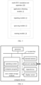
- the apparatus 100 includes: an application obtaining module 11, an inputting module 12, a querying module 13, and a running module 14.
- Each functional module is described in detail below.
- the application obtaining module 11 is configured to obtain a pre-developed application applied to a target ECU.
- the inputting module 12 is configured to input the application into a pre-built multi-ECU simulation environment.
- the querying module 13 is configured to obtain a target simulated ECU by querying, in the multi-ECU simulation environment, a simulated vehicle-mounted ECU having a unique identifier the same as the target ECU.
- the running module 14 is configured to simulate a communication process of the target simulated ECU via a simulated CAN or a simulated Internet network in the multi-ECU simulation environment, run the application based on the target simulated ECU, and output a running result of the application.
- the inputting module 12 inputs the application to be tested into the pre-built multi-ECU simulation environment.
- the querying module 13 queries, in the multi-ECU simulation environment, the simulated vehicle-mounted ECU having the same unique identifier as the target ECU, to obtain the target simulated ECU.
- the running module 14 runs the application and outputs the running result of the application through the target simulated ECU. Since the multi-ECU simulation environment includes at least one DoIP simulation node and a plurality of simulated vehicle-mounted ECUs, each of the simulated vehicle-mounted ECUs performs communication via a simulated CAN bus or a simulated DoIP network based on the DoIP simulation node.
- the apparatus 100 further includes:
- a corresponding configuration file needs to be imported according to an actual test scenario of the multi-ECU simulation environment.
- the CDD/ODX configuration file needs to be imported.
- a DBC configuration file needs to be imported.
- a lua configuration file can be imported to configure basic parameters of the ECU and the nodes state of the entire network, in order to assist in completing establishment of the simulation environment.
- the lua configuration file, the CDD/ODX configuration file, and the DBC configuration file may all be imported into the multi-ECU simulation environment.
- the currently developed business functions of the ECU are self-tested through the built multi-ECU simulation environment.
- a development iteration process can be accelerated by writing test cases in the simulation environment.
- the running module 14 when there are a plurality of target ECUs to which the application is applied, and there is only one IP address for the plurality of target ECUs, the running module 14 includes:
- the running module 14 when there are a plurality of target ECUs to which the application is applied, and there are two or more IP addresses for the plurality of target ECUs, the running module 14 includes:
- the application includes a diagnostic file
- the running module 14 includes:
- this diagnostic file includes a CDD/ODX file.
- the running module 14 includes:
- the embodiment parses the diagnostic file in a format of CDD or ODX, to realize a diagnostic interface for the ECU.
- the diagnostic file contains a communication protocol for diagnosis and required communication parameters, a diagnostic service and its format/sub-function on the ECU, a DID and an interpreted code value, a DTC and a corresponding error text.
- the running module 14 includes:
- first and “second” in the above modules/units are only used to distinguish between different modules/units and are not intended to indicate which module/unit has a higher priority or has other defining meanings.
- the terms “including” and “having” and any variations thereof are intended to cover non-exclusive inclusion, e.g., a process, method, system, product or apparatus comprising a series of steps or modules need not be limited to those steps or modules clearly listed, but other steps or modules that are not clearly listed or are inherent to the process, method, product or apparatus.
- the modules in this disclosure are classified only by logic, and there may be other ways of classifying the modules when implemented in practical applications.
- the multi-ECU simulation test apparatus can be specifically limited with reference to the limitations on the multi-ECU simulation test method described above, and will not be repeated herein.
- the modules of the above multi-ECU simulation test apparatus may be realized in whole or in part by means of software, hardware and combinations thereof.
- Each of the above modules may be embedded in or independently of the processor of the computer device in the form of hardware, or may be stored in the memory of the computer device in the form of software, so as to facilitate the processor to call for the execution of the corresponding operation of each of the above modules.
- a computer device such as a terminal, and its internal structural diagram may be shown in FIG. 6 .
- the computer device includes a processor connected via a system bus, a memory, a network interface, a display screen and an input device.
- the processor of the computer device is used to provide computing and control capabilities.
- the memory of the computer device includes a storage medium and an internal memory.
- the storage medium includes a non-volatile storage medium and/or a volatile storage medium.
- the storage medium stores an operating system and a computer program.
- the internal memory provides an environment for the operation of the operating system and the computer program in the storage medium.
- the computer device has a network interface for communicating with an external device via a network connection.
- the computer program is executed by a processor to implement a multi-ECU simulation test method.
- a computer device which includes a memory, a processor and a computer program stored on the memory and executable by the processor.
- the steps of the multi-ECU simulation test method of the above embodiments are implemented, such as steps 101-104 shown in FIG. 2 and other extensions of the method and related steps.
- the functions of each module/unit of the multi-ECU simulation test apparatus in the above embodiments are realized, such as the functions of modules 11-14 shown in FIG. 5 , which are not repeated herein to avoid repetition.
- the processor may be an ECU, a Central Processing Unit (CPU) or other general processors, a Digital Signal Processor (DSP), an Application Specific Integrated Circuit (ASIC), a Field-Programmable Gate Array (FPGA) or other programmable logic devices, discrete gates, transistor logic devices or discrete hardware components.
- the general processor may be a microprocessor or any conventional processor.
- the processor is a control center of the computer device and connects the parts of the entire computer device using various interfaces and circuits.
- the memory may be used to store the computer programs and/or modules.
- the processor implements various functions of the computer device by running or executing the computer programs and/or modules stored in the memory, and by calling data stored in the memory.
- the memory mainly includes a program storage area and a data storage area.
- the program storage area may store an operating system, and applications required for at least one function (e.g. a sound playback function, an image playback function, etc.).
- the data storage area may store data (e.g. audio data, video data, etc.) created in accordance with the use of the mobile phone.
- the memory may be integrated in the processor or may be provided separately from the processor.
- a computer readable storage medium having computer programs stored thereon is provided.
- the steps of the multi-ECU simulation test method of the above embodiments are executed, such as steps 101-104 shown in FIG. 2 and other extensions of the method and related steps.
- the functions of the modules/units of the multi-ECU simulation test apparatus in the above embodiment are implemented, such as the functions of modules 11-14 shown in FIG. 5 , which will not be repeated herein to avoid repetition.
- the computer-readable storage medium is a non-volatile computer-readable storage medium.
- a computer program product including computer programs is provided.
- the computer programs are executed by a processor, the multi-ECU simulation test method in the above embodiments is implemented.
- a computer program including computer program codes is provided.
- the computer program codes are run on a computer, the computer is caused to perform the multi-ECU simulation test method in the above embodiments.
- the computer programs are stored in a non-volatile and/or volatile computer-readable storage medium.
- the processes of the embodiments of the above methods can be implemented.
- Any reference to a memory, storage device, database or other mediums used in the embodiments of the disclosure may include a non-volatile and/or volatile memory.
- the non-volatile memory may include a Read-Only Memory (ROM), a programmable ROM (PROM), an electrically programmable ROM (EPROM), an electrically erasable programmable ROM (EEPROM) or a flash memory.
- the volatile memory may include a Random Access Memory (RAM) or an external cache memory.
- RAM Random Access Memory
- the RAM is available in a variety of forms, such as a static RAM (SRAM), a dynamic RAM (DRAM), a synchronous DRAM (SDRAM), a dual data rate SDRAM (DDRSDRAM), an enhanced SDRAM (ESDRAM), a Synchlink DRAM (SLDRAM), a Rambus Direct RAM (RDRAM), a Direct Rambus RAM (DRRAM), and a Rambus Dynamic RAM (RDRAM).
- SRAM static RAM
- DRAM dynamic RAM
- SDRAM synchronous DRAM
- DDRSDRAM dual data rate SDRAM
- ESDRAM enhanced SDRAM
- SLDRAM Synchlink DRAM
- RDRAM Rambus Direct RAM
- DRRAM Direct Rambus RAM
- RDRAM Rambus Dynamic RAM
Landscapes
- Engineering & Computer Science (AREA)
- Theoretical Computer Science (AREA)
- Physics & Mathematics (AREA)
- General Physics & Mathematics (AREA)
- General Engineering & Computer Science (AREA)
- Computer Hardware Design (AREA)
- Quality & Reliability (AREA)
- Automation & Control Theory (AREA)
- Geometry (AREA)
- Evolutionary Computation (AREA)
- Computer Networks & Wireless Communication (AREA)
- Signal Processing (AREA)
- Aviation & Aerospace Engineering (AREA)
- Computational Mathematics (AREA)
- Mathematical Analysis (AREA)
- Mathematical Optimization (AREA)
- Pure & Applied Mathematics (AREA)
- Debugging And Monitoring (AREA)
- Test And Diagnosis Of Digital Computers (AREA)
Applications Claiming Priority (2)
| Application Number | Priority Date | Filing Date | Title |
|---|---|---|---|
| CN202111619176.1A CN115437337A (zh) | 2021-12-27 | 2021-12-27 | 多ecu的仿真测试方法、装置、计算机设备及存储介质 |
| PCT/CN2022/140837 WO2023125213A1 (zh) | 2021-12-27 | 2022-12-21 | 多ecu的仿真测试方法、装置、计算机设备及存储介质 |
Publications (2)
| Publication Number | Publication Date |
|---|---|
| EP4459401A1 true EP4459401A1 (de) | 2024-11-06 |
| EP4459401A4 EP4459401A4 (de) | 2025-05-21 |
Family
ID=84271591
Family Applications (1)
| Application Number | Title | Priority Date | Filing Date |
|---|---|---|---|
| EP22914467.0A Pending EP4459401A4 (de) | 2021-12-27 | 2022-12-21 | Verfahren und vorrichtung zum testen einer multi-ecu-simulation, computervorrichtung und speichermedium |
Country Status (4)
| Country | Link |
|---|---|
| US (1) | US20250060737A1 (de) |
| EP (1) | EP4459401A4 (de) |
| CN (1) | CN115437337A (de) |
| WO (1) | WO2023125213A1 (de) |
Families Citing this family (16)
| Publication number | Priority date | Publication date | Assignee | Title |
|---|---|---|---|---|
| CN115437337A (zh) * | 2021-12-27 | 2022-12-06 | 北京罗克维尔斯科技有限公司 | 多ecu的仿真测试方法、装置、计算机设备及存储介质 |
| US20240385952A1 (en) * | 2023-05-18 | 2024-11-21 | Toyota Motor North America, Inc. | Dynamically configuring a network of ecus |
| CN116702377A (zh) * | 2023-08-04 | 2023-09-05 | 华侨大学 | 一种自动化移动机械的仿真方法、装置、设备及存储介质 |
| US20250166253A1 (en) * | 2023-11-17 | 2025-05-22 | Shanghai Tosun Technology Ltd. | Method and apparatus for synchronously displaying measurement data and computer readable storage medium |
| US12547363B2 (en) | 2023-11-17 | 2026-02-10 | Shanghai Tosun Technology Ltd. | System for synchronously displaying measurement data and execution method thereof |
| CN117614847B (zh) * | 2023-11-22 | 2024-08-13 | 广东工业大学 | 采集执行单元的仿真方法、计算机设备 |
| CN117640283B (zh) * | 2023-11-23 | 2024-06-11 | 广州致远电子股份有限公司 | 一种车载以太网分析系统 |
| CN117762042B (zh) * | 2023-12-22 | 2025-04-18 | 深圳世冠数智科技有限公司 | 一种基于dds的联合仿真方法及相关装置 |
| US20250371919A1 (en) * | 2024-06-03 | 2025-12-04 | Snap-On Incorporated | Methods and Systems for Selective Communication with Electronic Control Units of a Vehicle |
| CN118885393B (zh) * | 2024-07-17 | 2025-09-19 | 重庆赛力斯凤凰智创科技有限公司 | 一种面向服务架构测试系统、生成方法、设备及存储介质 |
| CN118915490B (zh) * | 2024-08-05 | 2025-03-28 | 山东泽鹿安全技术有限公司 | 基于半实物仿真的车辆漏洞攻击效果测试系统及测试方法 |
| CN118606128B (zh) * | 2024-08-05 | 2024-10-18 | 山东泽鹿安全技术有限公司 | 用于车辆安全漏洞的多型号模拟测试方法及存储介质 |
| CN119449650A (zh) * | 2024-10-28 | 2025-02-14 | 中国第一汽车股份有限公司 | 控制器区域网络通讯接口测试方法、装置、设备及车辆 |
| CN119718961A (zh) * | 2025-02-27 | 2025-03-28 | 质子汽车科技有限公司 | 一种车联网应用程序测试方法和上位机设备 |
| CN119907024B (zh) * | 2025-03-14 | 2025-12-26 | 国汽(北京)智能网联汽车研究院有限公司 | 一种基于v2x通信的spat消息的质量测评方法及装置 |
| CN120196554B (zh) * | 2025-05-27 | 2025-08-22 | 北京智慧云测设备技术有限公司 | 一种车载ecu固件的动态模拟方法及设备 |
Family Cites Families (14)
| Publication number | Priority date | Publication date | Assignee | Title |
|---|---|---|---|---|
| EP2801872B1 (de) * | 2013-05-06 | 2018-06-06 | dSPACE digital signal processing and control engineering GmbH | Testeinrichtung zum Test eines virtuellen Steuergeräts |
| EP2851815A1 (de) * | 2013-09-18 | 2015-03-25 | dSPACE digital signal processing and control engineering GmbH | Testeinrichtung zum Echtzeittest eines virtuellen Steuergeräts |
| CN104536434A (zh) * | 2014-12-15 | 2015-04-22 | 华晨汽车集团控股有限公司 | 车辆网络总线仿真与测试方法 |
| KR101630729B1 (ko) * | 2015-04-16 | 2016-06-24 | 현대자동차주식회사 | 차량에 최적화된 이더넷 통신 제공 방법 및 시스템 |
| KR101745456B1 (ko) * | 2016-05-12 | 2017-06-09 | 아주대학교산학협력단 | HiL 시뮬레이션 환경에서 대용량 데이터를 전송하기 위한 전자제어 장치, 이를 포함하는 시스템 및 그 방법 |
| CN107943008B (zh) * | 2017-12-14 | 2020-11-10 | 上汽通用五菱汽车股份有限公司 | 基于vt系统的自动化诊断测试方法 |
| CN111698042A (zh) * | 2019-03-14 | 2020-09-22 | 上海锐勤电子科技有限公司 | 车载通讯网络仿真测试方法及系统 |
| JP7225064B2 (ja) * | 2019-09-12 | 2023-02-20 | 株式会社日立ソリューションズ | シミュレーション方法およびシミュレーションプログラム |
| CN112068530A (zh) * | 2020-09-01 | 2020-12-11 | 华人运通(江苏)技术有限公司 | 一种ecu自动化测试方法、系统、存储介质及装置 |
| CN113253704B (zh) * | 2020-12-29 | 2022-08-19 | 际络科技(上海)有限公司 | 车辆ecu的仿真测试方法、装置、系统和电子设备 |
| CN113485920B (zh) * | 2021-07-01 | 2024-02-02 | 中瓴智行(成都)科技有限公司 | 实现DoIP实体的方法、装置、可读存储介质及电子设备 |
| CN113791605B (zh) * | 2021-09-13 | 2023-10-27 | 一汽解放汽车有限公司 | 一种测试方法、装置、设备及存储介质 |
| CN113759879B (zh) * | 2021-09-28 | 2023-07-04 | 重庆长安汽车股份有限公司 | 一种基于L3整车架构的车载以太网DoIP诊断刷写测试方法及系统 |
| CN115437337A (zh) * | 2021-12-27 | 2022-12-06 | 北京罗克维尔斯科技有限公司 | 多ecu的仿真测试方法、装置、计算机设备及存储介质 |
-
2021
- 2021-12-27 CN CN202111619176.1A patent/CN115437337A/zh active Pending
-
2022
- 2022-12-21 US US18/724,705 patent/US20250060737A1/en active Pending
- 2022-12-21 WO PCT/CN2022/140837 patent/WO2023125213A1/zh not_active Ceased
- 2022-12-21 EP EP22914467.0A patent/EP4459401A4/de active Pending
Also Published As
| Publication number | Publication date |
|---|---|
| US20250060737A1 (en) | 2025-02-20 |
| WO2023125213A1 (zh) | 2023-07-06 |
| CN115437337A (zh) | 2022-12-06 |
| EP4459401A4 (de) | 2025-05-21 |
Similar Documents
| Publication | Publication Date | Title |
|---|---|---|
| EP4459401A1 (de) | Verfahren und vorrichtung zum testen einer multi-ecu-simulation, computervorrichtung und speichermedium | |
| CN115242689B (zh) | 一种车载网关测试方法、系统及计算机可读存储介质 | |
| KR101630729B1 (ko) | 차량에 최적화된 이더넷 통신 제공 방법 및 시스템 | |
| CN112953774B (zh) | 一种网络拓扑生成方法、系统、设备及计算机存储介质 | |
| US20220150317A1 (en) | Universal software communication bus | |
| US20140343915A1 (en) | Test environment configuration apparatus and method of operating network simulation apparatus using same | |
| US20170048359A1 (en) | Method and device for transmitting a message in a vehicle | |
| CN113485920B (zh) | 实现DoIP实体的方法、装置、可读存储介质及电子设备 | |
| CN113468070A (zh) | 车载以太网的一致性测试方法 | |
| CN106850419A (zh) | 车载网关和用于车载网关的方法 | |
| CN114328229A (zh) | 一种空中下载技术测试系统 | |
| CN115543840A (zh) | 基于dds通讯的测试方法、装置、测试设备及存储介质 | |
| Iwakami et al. | AUTOSAR AP and ROS 2 collaboration framework | |
| CN117215284A (zh) | 车辆远程诊断方法、装置、车辆、系统、电子设备及介质 | |
| WO2023216901A1 (zh) | 配置切片策略的方法、装置、网络设备及存储介质 | |
| CN117527938A (zh) | 应用于车辆的通信协议栈自动化配置方法、装置及设备 | |
| CN113419952B (zh) | 云服务管理场景测试装置与方法 | |
| CN113722267B (zh) | 一种芯片配置方法及装置 | |
| CN117827555A (zh) | 硬件在环测试方法、装置、电子设备以及存储介质 | |
| CN116389326A (zh) | 基于DoIP的协议、刷新测试方法、系统、设备及介质 | |
| CN119182650A (zh) | 一种通信异常处理方法、装置和存储介质 | |
| CN116455869A (zh) | 基于Kubernetes高效配置公网域名方法和系统 | |
| CN115694747A (zh) | 一种数据冗余保护方法、装置、计算机设备和存储介质 | |
| CN118200866B (zh) | 车控命令执行方法、装置、电子设备及存储介质 | |
| ElHakim et al. | Let's DO-Automotive Platform for Interoperability |
Legal Events
| Date | Code | Title | Description |
|---|---|---|---|
| STAA | Information on the status of an ep patent application or granted ep patent |
Free format text: STATUS: THE INTERNATIONAL PUBLICATION HAS BEEN MADE |
|
| PUAI | Public reference made under article 153(3) epc to a published international application that has entered the european phase |
Free format text: ORIGINAL CODE: 0009012 |
|
| STAA | Information on the status of an ep patent application or granted ep patent |
Free format text: STATUS: REQUEST FOR EXAMINATION WAS MADE |
|
| 17P | Request for examination filed |
Effective date: 20240726 |
|
| AK | Designated contracting states |
Kind code of ref document: A1 Designated state(s): AL AT BE BG CH CY CZ DE DK EE ES FI FR GB GR HR HU IE IS IT LI LT LU LV MC ME MK MT NL NO PL PT RO RS SE SI SK SM TR |
|
| DAV | Request for validation of the european patent (deleted) | ||
| DAX | Request for extension of the european patent (deleted) | ||
| A4 | Supplementary search report drawn up and despatched |
Effective date: 20250422 |
|
| RIC1 | Information provided on ipc code assigned before grant |
Ipc: G05B 17/02 20060101ALI20250414BHEP Ipc: G06F 30/20 20200101ALI20250414BHEP Ipc: G06F 11/3698 20250101ALI20250414BHEP Ipc: G06F 11/22 20060101ALI20250414BHEP Ipc: G06F 11/3668 20250101ALI20250414BHEP Ipc: G05B 23/02 20060101AFI20250414BHEP |