EP4459322A1 - Schätzvorrichtung, schätzverfahren und programm - Google Patents
Schätzvorrichtung, schätzverfahren und programm Download PDFInfo
- Publication number
- EP4459322A1 EP4459322A1 EP22915571.8A EP22915571A EP4459322A1 EP 4459322 A1 EP4459322 A1 EP 4459322A1 EP 22915571 A EP22915571 A EP 22915571A EP 4459322 A1 EP4459322 A1 EP 4459322A1
- Authority
- EP
- European Patent Office
- Prior art keywords
- living body
- complex transfer
- distance
- transmission antenna
- reception
- Prior art date
- Legal status (The legal status is an assumption and is not a legal conclusion. Google has not performed a legal analysis and makes no representation as to the accuracy of the status listed.)
- Pending
Links
Images


Classifications
-
- G—PHYSICS
- G01—MEASURING; TESTING
- G01S—RADIO DIRECTION-FINDING; RADIO NAVIGATION; DETERMINING DISTANCE OR VELOCITY BY USE OF RADIO WAVES; LOCATING OR PRESENCE-DETECTING BY USE OF THE REFLECTION OR RERADIATION OF RADIO WAVES; ANALOGOUS ARRANGEMENTS USING OTHER WAVES
- G01S13/00—Systems using the reflection or reradiation of radio waves, e.g. radar systems; Analogous systems using reflection or reradiation of waves whose nature or wavelength is irrelevant or unspecified
- G01S13/02—Systems using reflection of radio waves, e.g. primary radar systems; Analogous systems
- G01S13/06—Systems determining position data of a target
- G01S13/08—Systems for measuring distance only
- G01S13/32—Systems for measuring distance only using transmission of continuous waves, whether amplitude-, frequency-, or phase-modulated, or unmodulated
- G01S13/34—Systems for measuring distance only using transmission of continuous waves, whether amplitude-, frequency-, or phase-modulated, or unmodulated using transmission of continuous, frequency-modulated waves while heterodyning the received signal, or a signal derived therefrom, with a locally-generated signal related to the contemporaneously transmitted signal
-
- G—PHYSICS
- G01—MEASURING; TESTING
- G01S—RADIO DIRECTION-FINDING; RADIO NAVIGATION; DETERMINING DISTANCE OR VELOCITY BY USE OF RADIO WAVES; LOCATING OR PRESENCE-DETECTING BY USE OF THE REFLECTION OR RERADIATION OF RADIO WAVES; ANALOGOUS ARRANGEMENTS USING OTHER WAVES
- G01S13/00—Systems using the reflection or reradiation of radio waves, e.g. radar systems; Analogous systems using reflection or reradiation of waves whose nature or wavelength is irrelevant or unspecified
- G01S13/02—Systems using reflection of radio waves, e.g. primary radar systems; Analogous systems
- G01S13/06—Systems determining position data of a target
- G01S13/08—Systems for measuring distance only
- G01S13/10—Systems for measuring distance only using transmission of interrupted, pulse modulated waves
-
- G—PHYSICS
- G01—MEASURING; TESTING
- G01S—RADIO DIRECTION-FINDING; RADIO NAVIGATION; DETERMINING DISTANCE OR VELOCITY BY USE OF RADIO WAVES; LOCATING OR PRESENCE-DETECTING BY USE OF THE REFLECTION OR RERADIATION OF RADIO WAVES; ANALOGOUS ARRANGEMENTS USING OTHER WAVES
- G01S13/00—Systems using the reflection or reradiation of radio waves, e.g. radar systems; Analogous systems using reflection or reradiation of waves whose nature or wavelength is irrelevant or unspecified
- G01S13/003—Bistatic radar systems; Multistatic radar systems
-
- G—PHYSICS
- G01—MEASURING; TESTING
- G01S—RADIO DIRECTION-FINDING; RADIO NAVIGATION; DETERMINING DISTANCE OR VELOCITY BY USE OF RADIO WAVES; LOCATING OR PRESENCE-DETECTING BY USE OF THE REFLECTION OR RERADIATION OF RADIO WAVES; ANALOGOUS ARRANGEMENTS USING OTHER WAVES
- G01S13/00—Systems using the reflection or reradiation of radio waves, e.g. radar systems; Analogous systems using reflection or reradiation of waves whose nature or wavelength is irrelevant or unspecified
- G01S13/02—Systems using reflection of radio waves, e.g. primary radar systems; Analogous systems
- G01S13/06—Systems determining position data of a target
- G01S13/08—Systems for measuring distance only
- G01S13/32—Systems for measuring distance only using transmission of continuous waves, whether amplitude-, frequency-, or phase-modulated, or unmodulated
- G01S13/34—Systems for measuring distance only using transmission of continuous waves, whether amplitude-, frequency-, or phase-modulated, or unmodulated using transmission of continuous, frequency-modulated waves while heterodyning the received signal, or a signal derived therefrom, with a locally-generated signal related to the contemporaneously transmitted signal
- G01S13/347—Systems for measuring distance only using transmission of continuous waves, whether amplitude-, frequency-, or phase-modulated, or unmodulated using transmission of continuous, frequency-modulated waves while heterodyning the received signal, or a signal derived therefrom, with a locally-generated signal related to the contemporaneously transmitted signal using more than one modulation frequency
-
- G—PHYSICS
- G01—MEASURING; TESTING
- G01S—RADIO DIRECTION-FINDING; RADIO NAVIGATION; DETERMINING DISTANCE OR VELOCITY BY USE OF RADIO WAVES; LOCATING OR PRESENCE-DETECTING BY USE OF THE REFLECTION OR RERADIATION OF RADIO WAVES; ANALOGOUS ARRANGEMENTS USING OTHER WAVES
- G01S7/00—Details of systems according to groups G01S13/00, G01S15/00, G01S17/00
- G01S7/02—Details of systems according to groups G01S13/00, G01S15/00, G01S17/00 of systems according to group G01S13/00
- G01S7/28—Details of pulse systems
- G01S7/285—Receivers
-
- G—PHYSICS
- G01—MEASURING; TESTING
- G01S—RADIO DIRECTION-FINDING; RADIO NAVIGATION; DETERMINING DISTANCE OR VELOCITY BY USE OF RADIO WAVES; LOCATING OR PRESENCE-DETECTING BY USE OF THE REFLECTION OR RERADIATION OF RADIO WAVES; ANALOGOUS ARRANGEMENTS USING OTHER WAVES
- G01S7/00—Details of systems according to groups G01S13/00, G01S15/00, G01S17/00
- G01S7/02—Details of systems according to groups G01S13/00, G01S15/00, G01S17/00 of systems according to group G01S13/00
- G01S7/40—Means for monitoring or calibrating
- G01S7/4004—Means for monitoring or calibrating of parts of a radar system
- G01S7/4017—Means for monitoring or calibrating of parts of a radar system of HF systems
-
- G—PHYSICS
- G01—MEASURING; TESTING
- G01S—RADIO DIRECTION-FINDING; RADIO NAVIGATION; DETERMINING DISTANCE OR VELOCITY BY USE OF RADIO WAVES; LOCATING OR PRESENCE-DETECTING BY USE OF THE REFLECTION OR RERADIATION OF RADIO WAVES; ANALOGOUS ARRANGEMENTS USING OTHER WAVES
- G01S7/00—Details of systems according to groups G01S13/00, G01S15/00, G01S17/00
- G01S7/02—Details of systems according to groups G01S13/00, G01S15/00, G01S17/00 of systems according to group G01S13/00
- G01S7/41—Details of systems according to groups G01S13/00, G01S15/00, G01S17/00 of systems according to group G01S13/00 using analysis of echo signal for target characterisation; Target signature; Target cross-section
- G01S7/415—Identification of targets based on measurements of movement associated with the target
-
- G—PHYSICS
- G01—MEASURING; TESTING
- G01S—RADIO DIRECTION-FINDING; RADIO NAVIGATION; DETERMINING DISTANCE OR VELOCITY BY USE OF RADIO WAVES; LOCATING OR PRESENCE-DETECTING BY USE OF THE REFLECTION OR RERADIATION OF RADIO WAVES; ANALOGOUS ARRANGEMENTS USING OTHER WAVES
- G01S13/00—Systems using the reflection or reradiation of radio waves, e.g. radar systems; Analogous systems using reflection or reradiation of waves whose nature or wavelength is irrelevant or unspecified
- G01S13/02—Systems using reflection of radio waves, e.g. primary radar systems; Analogous systems
- G01S13/06—Systems determining position data of a target
- G01S13/46—Indirect determination of position data
- G01S2013/466—Indirect determination of position data by Trilateration, i.e. two antennas or two sensors determine separately the distance to a target, whereby with the knowledge of the baseline length, i.e. the distance between the antennas or sensors, the position data of the target is determined
Definitions
- the present disclosure relates to an estimating device, an estimating method, and so on, for estimating the distance or position of a living body by using radio signals.
- Patent Literature 1 to 4 disclose techniques of estimating the position and state of a person that is a detection target by analyzing a component including a Doppler shift using difference calculation.
- PTL 4 and 5 disclose Doppler sensors that use orthogonal frequency division multiplexing (OFDM) signals.
- OFDM orthogonal frequency division multiplexing
- the present disclosure is conceived in view of the above-described circumstances, and has as an object to provide an estimating device, and so on, capable of more accurately estimating the distance from the estimating device to a living body, and so on.
- an estimating device that estimates a distance to a living body and includes: a transmission signal generator that generates a multicarrier signal obtained by modulating a plurality of subcarrier signals; a transmission antenna including M transmission antenna elements, where M is a natural number greater than or equal to 1; a transmitter that causes the transmission antenna to transmit the multicarrier signal, by processing and outputting the multicarrier signal to the transmission antenna; a reception antenna including N reception antenna elements, where N is a natural number greater than or equal to 1; a receiver that measures, for a first period equivalent to a cycle derived from an activity of the living body, a plurality of reception signals which are received by each of the N reception antenna elements and include a reflected signal which is the multicarrier signal transmitted from each of the M transmission antenna elements that has been reflected or dispersed by the living body; a complex transfer function calculator that calculates a plurality of complex transfer functions for each of a plurality of subcar
- an estimating method is an estimating method performed by an estimating device including a transmission antenna including M transmission antenna elements, where M is a natural number greater than or equal to 1, and a reception antenna including N reception antenna elements, where N is a natural number greater than or equal to 1.
- the estimating method includes: generating a multicarrier signal obtained by modulating a plurality of subcarrier signals; causing the transmission antenna to transmit the multicarrier signal, by processing and outputting the multicarrier signal to the transmission antenna; measuring, for a first period equivalent to a cycle derived from an activity of a living body, a plurality of reception signals which are received by each of the N reception antenna elements and include a reflected signal which is the multicarrier signal transmitted from each of the M transmission antenna elements that has been reflected or dispersed by the living body; calculating a plurality of complex transfer functions for each of a plurality of subcarriers to which the plurality of subcarrier signals correspond, using the plurality of reception signals measured in the first period, the plurality of complex transfer functions indicating a propagation characteristic between a transmission antenna element and a reception antenna element in each of M ⁇ N combinations which are combinations of each of the M transmission antenna elements and each of the N reception antenna elements; calculating, for each of the plurality of subcarriers, a living body
- a method that uses radio signals is being considered as a method for knowing the position of a person.
- PTL 1 and 2 disclose transmitting a radio signal over a predetermined area, receiving, using an antenna, the radio signal reflected by a detection target, and estimating a complex transfer function between transmission and reception antennas.
- a complex transfer function is a function of a complex number representing a relationship between input and output, and, here, represents propagation characteristics between transmission and reception antennas. The number of elements of the complex transfer function is equivalent to the product of the number of transmission antennas and the number of reception antennas.
- PTL 3 discloses estimating the posture of a living body by using a radar cross-section (RCS) calculated from received power, with the same configuration as in PTL 2.
- RCS is an index indicating the area of an object that reflected a transmission wave, and the RCS of a living body changes in various ways according to the posture.
- PTL 1 discloses that it is possible to know the position or state of a person that is a detection target by analyzing a component including a Doppler shift, using Fourier transform. More specifically, the temporal change of an element of a complex transfer function is recorded, and the temporal waveform thereof is Fourier-transformed. Through biological activity such as respiration or heartbeat, a living body such as a person exerts a small Doppler effect on the reflected wave. Therefore, a component including a Doppler shift includes the influence of the person.
- a component that does not include a Doppler shift is a component that is not influenced by the person, that is, a component corresponding to a reflected wave from a fixed object or a direct wave between transmission and reception antennas. Specifically, it is possible to know the position or state of a person that is a detection target, by using a component included in a predetermined frequency range in a Flourier-transformed waveform.
- PTL 2 discloses a method of recording a temporal change in an element of a complex transfer function, and extracting a component including a small Doppler shift including the influence of a living body by analyzing difference information of the temporal change. Specifically, it is possible to know the position or state of a person that is a detection target by using the difference information.
- PTL 3 discloses an OFDM Doppler radar that transmits a pulse using an OFDM signal, and detects a Doppler shift caused by a traveling body that is a target.
- PTL 4 discloses, with regard to an OFDM Doppler radar, a high-speed processing method that does not require Fourier transform.
- PTL 6 and 7 disclose techniques for improving the accuracy of estimation of complex transfer functions between transmission and reception antennas, by transmitting an OFDM signal.
- PTL 5 discloses that received noise components can be reduced by averaging complex transfer functions on a subcarrier basis
- PTL 7 discloses that received noise components can be reduced by selecting a subcarrier having the maximum reception power.
- the technique in NPL 1 by transmitting and receiving signals having a plurality of frequencies using a measuring device such as a network analyzer, it is possible to estimate the time of flight (ToF) and distance, which can be computed from the ToF, between a transmission antenna and a reception antenna.
- a measuring device such as a network analyzer
- FMCW frequency modulated continuous wave
- this makes use of the property in which, when two signals having different frequencies are transmitted at the same phase, the phase received by the reception antenna changes depending on the frequency difference between signals and the propagation distance between the antennas.
- the technique in NPL 1 improves resolution by performing ToF estimation using the multiple signal classification (MUSIC) method.
- MUSIC multiple signal classification
- the transmission side and reception side it is necessary for the transmission side and reception side to either operate with the same reference frequency or be synchronized with high accuracy, and thus the technique cannot be used in household appliances such as a wireless LAN. Furthermore, only the distance between antennas can be estimated, and, for example, the distance to a living body that is not equipped with a special device cannot be estimated.
- the inventors arrived at inventing, with high accuracy and low cost by using an existing transmission device, an estimating device, etc., capable of more accurately estimating the distance from the estimating device to a living body, and so on, using a multicarrier radio signal represented by an OFDM signal.
- an estimating device that estimates a distance to a living body and includes: a transmission signal generator that generates a multicarrier signal obtained by modulating a plurality of subcarrier signals; a transmission antenna including M transmission antenna elements, where M is a natural number greater than or equal to 1; a transmitter that causes the transmission antenna to transmit the multicarrier signal, by processing and outputting the multicarrier signal to the transmission antenna; a reception antenna including N reception antenna elements, where N is a natural number greater than or equal to 1; a receiver that measures, for a first period equivalent to a cycle derived from an activity of the living body, a plurality of reception signals which are received by each of the N reception antenna elements and include a reflected signal which is the multicarrier signal transmitted from each of the M transmission antenna elements that has been reflected or dispersed by the living body; a complex transfer function calculator that calculates a plurality of complex transfer functions for each of a plurality of subcarriers to which the
- a living body radar that measures distance to a living body can be realized by repurposing an existing communication device by using a multicarrier signal such as an OFDM signal as a transmission signal.
- a multicarrier signal such as an OFDM signal
- receiving devices of multicarrier signals such as OFDM signals are already widely used as mobile phones, television broadcast receiving devices, wireless LAN devices, and so on, and thus a living body radar that measures the distance to a living body can be realized at a lower cost than when non-modulated signals are used.
- An estimating device is the estimating device according to the first aspect, further including: a calibrator that calculates a correction value for correcting a phase error in a subcarrier direction based on (i) ideal complex transfer functions between the M transmission antenna elements and the N reception antenna elements obtainable based on an inter-antenna distance between the M transmission antenna elements and the N reception antenna elements and (ii) a reference complex transfer function matrix including M ⁇ N complex transfer functions measured in a second period, and corrects the plurality of complex transfer functions for the first period.
- An estimating device is the estimating device according to the first aspect or the second aspect, wherein at least one of M or N is greater than or equal to 2, and the estimating device further includes: an angle estimator that calculates, using the plurality of complex transfer functions calculated by the complex transfer function calculator, a first angle that is an angle defined by two or more antenna elements among the M transmission antenna elements and the N reception antenna elements; and a positioner that calculates the first distance from the first angle and the third distance, and calculates a position of the living body.
- the position of the living body relative to the estimating device can be more accurately estimated.
- An estimating device is the estimating device according to the first aspect or the second aspect, wherein at least one of M or N is greater than or equal to 3, and the estimator calculates, for each of the M ⁇ N combinations, an ellipse in which positions of the transmission element and the reception antenna element included in the combination are foci and a length of a major axis is the third distance, and estimates a position of the living body based on, among intersections of the M ⁇ N ellipses obtained by calculation, M ⁇ N intersections that are closest to each other.
- the position of the living body relative to the estimating device can be more accurately estimated.
- An estimating device is the estimating device according to any one of the first to fourth aspects, wherein the living body correlation matrix calculator calculates the living body correlation matrix by performing inverse Fourier transform in a subcarrier direction on the plurality of complex transfer functions.
- An estimating device is the estimating device according to any one of the first to fourth aspects, wherein the estimator estimates distance using a multiple signal classification (MUSIC) method.
- MUSIC multiple signal classification
- An estimating method is an estimating method performed by an estimating device including a transmission antenna including M transmission antenna elements, where M is a natural number greater than or equal to 1, and a reception antenna including N reception antenna elements, where N is a natural number greater than or equal to 1.
- the estimating method includes: generating a multicarrier signal obtained by modulating a plurality of subcarrier signals; causing the transmission antenna to transmit the multicarrier signal, by processing and outputting the multicarrier signal to the transmission antenna; measuring, for a first period equivalent to a cycle derived from an activity of a living body, a plurality of reception signals which are received by each of the N reception antenna elements and include a reflected signal which is the multicarrier signal transmitted from each of the M transmission antenna elements that has been reflected or dispersed by the living body; calculating a plurality of complex transfer functions for each of a plurality of subcarriers to which the plurality of subcarrier signals correspond, using the plurality of reception signals measured in the first period, the plurality of complex transfer functions indicating a propagation characteristic between a transmission antenna element and a reception antenna element in each of M ⁇ N combinations which are combinations of each of the M transmission antenna elements and each of the N reception antenna elements; calculating, for each of the plurality of subcarriers, a living body
- a living body radar that measures distance to a living body can be realized by repurposing an existing communication device by using a multicarrier signal such as an OFDM signal as a transmission signal.
- a multicarrier signal such as an OFDM signal
- receiving devices of multicarrier signals such as OFDM signals are already widely used as mobile phones, television broadcast receiving devices, wireless LAN devices, and so on, and thus a living body radar that measures the distance to a living body can be realized at a lower cost than when non-modulated signals are used.
- a program according to an eighth aspect of the present disclosure is a program for causing a computer to execute the estimating method according to the seventh aspect.
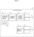
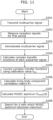
- FIG. 1 is a block diagram illustrating an example of a configuration of estimating device 10 according to Embodiment 1.
- FIG. 2 is a diagram illustrating an example of a detection target of estimating device 10 illustrated in FIG. 1 .
- Estimating device 10 illustrated in FIG. 1 includes transmission antenna 11, transmitter 12, transmission signal generator 13, reception antenna 21, receiver 22, complex transfer function calculator 23, calibrator 24, living body correlation matrix calculator 25, and estimator 26. Estimating device 10 estimates the distance from estimating device 10 to living body 50, with estimating device 10 as a directional or positional reference.
- Transmission antenna 11 includes M transmission antenna elements.
- M is a natural number greater than or equal to 1.
- transmission antenna 11 includes one transmission antenna element.
- the transmission antenna element transmits a multicarrier signal (transmission wave) generated by transmitter 12 to be described later.
- Transmission signal generator 13 generates a multicarrier signal obtained by modulating a plurality of subcarrier signals. Specifically, transmission signal generator 13 generates a plurality of subcarrier signals corresponding to a plurality of subcarriers having mutually different frequency bands, and generates a multicarrier signal by multiplexing the generated plurality of subcarriers. In the present embodiment, transmission signal generator 13 is exemplified as generating, as a multicarrier signal, an OFDM signal which has a high frequency band utilization efficiency and consists of S subcarriers.
- FDM frequency division multiplexing
- the signal generated by transmission signal generator 13 may be a signal that is shared with a signal used for communication.
- Transmitter 12 adds appropriate processing to the signal generated by transmission signal generator 13, to generate a transmission wave.
- the processing carried out here includes, for example, up-conversion in which the signal is converted from the intermediate frequency (IF) frequency band to the radio frequency (RF) frequency band, amplification in which the signal is amplified to the appropriate transmission level, etc.
- transmitter 12 outputs the processed multicarrier signal to transmission antenna 11 to thereby cause transmission antenna 11 to transmit the multicarrier signal. With this, the multicarrier signal is transmitted from the single transmission antenna element included in transmission antenna 11.
- Reception antenna 21 includes N reception antenna elements.
- N is a natural number greater than or equal to 1.
- reception antenna 21 includes one reception antenna element. Then, for example, as illustrated in FIG. 2 , the one reception antenna element receives a signal that was transmitted by the single transmission antenna element and reflected by living body 50 (i.e., a reception signal).
- Receiver 22 measures, for a first period equivalent to a cycle derived from an activity of living body 50, the reception signal that is received by the single reception antenna element and includes a reflected signal which is the multicarrier signal transmitted by the single transmission antenna element that has been reflected or dispersed by living body 50.
- a cycle derived from the activity of the living body is a living body-derived cycle (living body fluctuation cycle) which is a time period greater than or equal to a half-cycle of any of the cycles of respiration, heartbeat, and body motion of living body 50.
- Receiver 22 converts the high-frequency signal received by the single reception antenna element into a low-frequency signal on which signal processing can be performed. Then, receiver 22 demodulates the one OFDM signal into S subcarrier signals. Each of the S subcarrier signals is represented by an IQ symbol. Receiver 22 outputs, to complex transfer function calculator 23, the S ⁇ M sets (S sets in the present embodiment) of subcarrier signals obtained by converting the high-frequency signal received by the N (one in the present embodiment) reception antenna elements, for at least the first period. It should be noted that, receiver 22 may continue to measure the reception signal already received by reception antenna 21, and continuously or periodically transmit the S subcarrier signals (IQ symbols) to complex transfer function calculator 23.
- Complex transfer function calculator 23 using the reception signals measured in the first period by receiver 22, calculates, for each of the subcarriers to which the subcarrier signals correspond, a plurality of complex transfer functions indicating propagation characteristics between a transmission antenna element and a reception antenna element in each of M ⁇ N combinations (one combination in the present embodiment) which are the combinations of each of the M (one in the present embodiment) transmission antenna elements and each of the N (one in the present embodiment) reception antenna elements. It should be noted that the M ⁇ N combinations are all the obtainable one-to-one combinations between the M transmission antenna elements and the N reception antenna elements.
- complex transfer function calculator 23 calculates, using the S ⁇ M sets (S sets in the present embodiment) of subcarrier signals transmitted from receiver 22, complex transfer functions indicating the propagation characteristics between each of the transmission antenna elements and each of the reception antenna elements, for each of the S subcarrier signals. It should be noted that the calculated complex transfer function matrix also includes reflected waves that did not arrive via living body 50, such as direct waves and reflected waves derived from a fixed object.
- the method of calculating complex transfer functions from one subcarrier signal includes, for example, a method of dividing a reception IQ symbol using a known signal such as a pilot signal or a guard interval signal.
- a known signal such as a pilot signal or a guard interval signal.
- subcarrier signal S0 which serves as a reference, is used to divide the other subcarrier signals.
- Complex transfer function calculator 23 calculates the complex transfer functions for each of the S subcarrier signals, and outputs the obtained S complex transfer function matrices to calibrator 24.
- complex transfer function calculator 23 may constantly calculate the complex transfer function matrix, either continuously or on a regular basis, using each of the subcarrier signals outputted by receiver 22.
- the complex transfer function matrix that is normally calculated for use in processing by the communication device can also be used by estimating device 10.
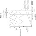
- Calibrator 24 obtains the calculated complex transfer function matrix h, and performs calibration for phase error in the frequency direction. Phase errors that require calibration will be described with reference to FIG. 3.
- FIG. 3 is a schematic diagram illustrating that the phase of a reception signal changes according to frequency and distance.
- inter-antenna distance When signals of different frequencies propagate through a space and are received, the amount of phase rotation by a transmission signal with respect to the reception signal is different depending on the frequency and the distance between the transmission antenna and the reception antenna (hereafter referred to as inter-antenna distance). For this reason, the inter-antenna distance can be calculated by transmitting and receiving signals having a plurality of already-known frequencies, measuring phase differences, and performing back calculation.
- the phase difference that is actually measured includes, not only the influence of spatial propagation between the transmission antenna and the reception antenna, but also error due to the influence of phase characteristics of internal circuits and antennas of the transmitter and receiver. For this reason, in order to correctly measure the inter-antenna distance, it is necessary to remove the phase error from the measured signal.
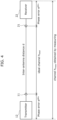
- FIG. 4 is a diagram illustrating the correspondence between the previously described phase error and a channel (complex transfer function).
- the phase error can be calculated by calculating the difference between channel h meas indicated by a matrix obtained by measurement and an ideal channel h ideal of the space indicated by a matrix that can be calculated from the inter-antenna distance. This is not limited to estimating the inter-antenna distance but also applies to the case of estimating the distance to living body 50.
- a phase error in the frequency direction refers to, among differences with respect to the phase of subcarrier signal S0 used as a reference calculated by complex transfer function calculator 23, a phase difference not resulting from spatial propagation between the antennas.
- the phase error includes the influence of the frequency characteristics of transmission antenna 11 and reception antenna 21, the electrical length of the internal circuitry of transmitter 12, the electrical length of the internal circuitry of receiver 22, and so on.
- the phase error includes phase difference e j ⁇ tx caused by transmission antenna 11 and transmitter 12 and phase error e j ⁇ rx caused by reception antenna 21 and receiver 22.
- Calibrator 24 performs calibration of a complex transfer function matrix, based on a frequency direction calibration value calculated using a predetermined method.
- calibrator 24 calculates h ideal , which is the ideal channel between antenna elements, based on pre-inputted inter-antenna distance d between a transmission antenna element and a reception antenna element.
- Inter-antenna distance d is, for example, a value obtained by a user actually measuring the distance between the transmission antenna element and the reception antenna element.
- h ideal is a vector represented by the complex number
- h ideal has S elements which is the subcarrier number.
- the i-th element is calculated as follows. [Math.
- h ideal i exp ⁇ jk i d
- k i is the wavenumber of the i-th subcarrier.
- h ideal is an ideal complex transfer function between the transmission antenna element and the reception transmission element obtainable based on the inter-antenna distance between the transmission antenna element and the reception transmission element.
- calibrator 24 obtains, from complex transfer function calculator 23, a reference complex transfer function matrix that includes M ⁇ N complex transfer functions measured in a second period, and serves as a reference. It should be noted that measurement of the reference complex transfer function matrix is preferably performed in a person-free state in which there is little influence from a living body, but may include the influence of a living body. An initial complex transfer function matrix obtained from complex transfer function calculator 23 may be used for the reference complex transfer function matrix.
- calibrator 24 may calculate a new reference complex transfer function matrix based on data of a timing at which fluctuation obtained by simultaneously calculating the temporal fluctuations of absolute values of complex transfer functions is small, and update the reference complex transfer function matrix with the new reference complex transfer function matrix calculated.
- the reference complex transfer function matrix is the vector h meas having an element number of S.
- calibration value h cal is the same as long as the reference complex transfer function matrix does not change, it is desirable to store the value in a memory, or the like, and use the stored value as calibration value h cal from the next time onward.
- calibrator 24 calibrates (corrects) complex transfer function matrix h according to the following equation, based on calibration value h cal .
- h ′ ⁇ h cal ⁇ h
- ⁇ h cal represents the phase angle of h cal
- ⁇ represents the Hadamard product which is the per element product.
- Calibrator 24 outputs the calibrated complex transfer function matrix h' obtained in the above-described manner to living body correlation matrix calculator 25 located downstream.
- Living body correlation matrix calculator 25 records sequentially in time series, which is the order in which the plurality of reception signals are measured, the plurality of calibrated complex transfer function matrices calculated by calibrator 24, for each of the subcarriers and each of the M ⁇ N combinations. Then, living body correlation matrix calculator 25 extracts, for each of the subcarriers and each of the M ⁇ N combinations, components of the living body from the calibrated complex transfer function matrices h' recorded in time series and measured for the first time period, to thereby calculate, for each of the subcarriers, a living body component transfer function matrix expressed by a M ⁇ N-dimension matrix.
- the living body component transfer function matrix is the extracted reflected wave or dispersed wave (living body component) included in the reception signal that passed via living body 50.
- the methods of calculating the living body component from the complex transfer functions recorded in time-series include the method using Fourier transform disclosed in PTL 1 and the method using difference information disclosed in PTL 2.
- living body component transfer function matrix h' fft can be calculated for each of frequency components included in the frequencies, for example, 0.1 Hz to 3 Hz, which can include the influence of activities of the living body.
- Solid line 1101 represents the fluctuation of the phase of each component of the living body component transfer function matrix according to the subcarrier frequency when living body 50 is present at a certain position.
- the phase is the difference from the phase in the frequency of subcarrier S0 serving as a reference during complex transfer function calculation. Since the length of the path of the radio wave reflected by living body 50 becomes shorter when living body 50 approaches the transmission antenna or reception antenna from the aforementioned position, the slope on the graph becomes gentle and becomes like broken line 1102. In principle, time of flight (ToF) or the distance to the living body can be estimated from this graph slope.
- ToF time of flight
- time domain living body component transfer function matrix h' ifft is calculated by further performing inverse Fourier transform in the subcarrier direction on living body component transfer function matrix h' fft , the time from when a signal including a living body component is transmitted from the transmitter to when the signal is received by the receiver is obtained.
- FIG. 6 illustrates the relationship between the time (column direction of the matrix) and the phase of time domain living body component transfer function matrix h' ifft .
- the phase changes of solid line 1101 and broken line 1102 in FIG. 5 appear as the peaks shown by solid line 1201 and broken line 1202, respectively.
- Living body component transfer function matrix h' fft is present for each frequency that may include vibration caused by the living body after the Fourier transform on h', and E[•] in Equation 5 denotes the average processing in the frequency direction.
- Estimator 26 performs ranging according to the MUSIC method, using correlation matrix R' f calculated by living body correlation matrix calculator 25. In other words, estimator 26 estimates distance using the MUSIC method. First, estimator 26 performs Eigendecomposition of correlation matrix R' f , and calculates eigenvector Us' corresponding to a signal and eigenvector U N ' corresponding to noise.
- eigenvectors corresponding to a signal are the vectors counted in order from a first eigenvector to the number of targets to be ranged, and is, for example, only the first eigenvector when the target is one person.
- the eigenvectors corresponding to a signal are the k eigenvectors from the first eigenvector to the k-th eigenvector.
- eigenvectors corresponding to noise refers to eigenvectors other than the eigenvectors corresponding to a signal.
- estimator 26 can calculate the third distance by calculating maximum value l. In this manner, estimator 26 estimates the third distance that is the sum of the first distance between transmission antenna 11 and living body 50 and the second distance by using the living body correlation matrix calculated for each of the plurality of subcarriers.
- FIG. 7 is a schematic diagram illustrating the position of the living body which is limited by the relationship between the living body, the transmission antenna element, and the reception antenna element, and by the third distance.
- the position of living body 50 in a plane is limited to the circumference of ellipse 1203 which has the positions of transmission antenna 11 and reception antenna 21 as foci.
- the position of living body 50 may be estimated from the intersection points of ellipses by using three or more transmission antennas or reception antennas and estimating a plurality of third distances.
- FIG. 8 is a schematic diagram illustrating the estimation of the position of a living body by using a plurality of reception antenna elements.
- Reception antenna 21 of estimation device 10 in this case includes three reception antenna elements 21a, 21b, and 21c. It should be noted that it is sufficient that reception antenna 21 includes three or more reception antenna elements, and is not limited to having three reception antenna elements. Moreover, instead of reception antenna 21 including three or more reception antenna elements, transmission antenna 11 may include three or more transmission antenna elements.
- the ellipse which has the positions of the transmission antenna element and reception antenna element included in the combination as foci and the length of its major axis as a third distance is calculated, and the position of living body 50 is estimated based on the three (that is, M ⁇ N) intersection points that are closest to each other among the intersection points between the three (that is, M ⁇ N) ellipses obtained from the calculation.
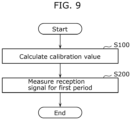
- FIG. 9 is a flowchart illustrating the estimation process by estimating device 10 according to the present embodiment.
- estimating device 10 calculates the calibration value (S100). Details of the processing in step S100 will be described with reference to FIG. 10 .
- estimation device 10 performs ranging for the third distance based on the calculated calibration value (S200). Details of the processing in step S200 will be described with reference to FIG. 11 .
- FIG. 10 is a flowchart illustrating the detailed processing involved in the calibration value calculation in step S100.
- estimating device 10 transmits, from the transmission antenna element, a multicarrier signal obtained by modulating S subcarriers (S101).
- estimating device 10 transmits the multicarrier signal from the transmission antenna element and measures received reception signals using the reception antenna element (S102).
- estimating device 10 performs multicarrier demodulation on the reception signals measured in the second period to demodulate the reception signals into S signal columns (S103).
- estimating device 10 calculates, from the reception signal of the subcarrier measured in the second period, complex transfer functions indicating the propagation characteristics between the transmission antenna element and the reception antenna element (S104). This process is performed in parallel or sequentially for the respective subcarriers. Since the details are as described above, description will be omitted here. The same applies to the following steps.
- estimation device 10 calculates ideal channel h ideal from the distance between the transmission antenna element and the reception antenna element provided in advance (S105).
- estimation device 10 calculates calibration value h cal according to Equation 2, based on ideal channel h ideal and the measured channel h meas (S106).
- FIG. 11 is a flowchart illustrating the detailed processing in the ranging in step S200.
- estimating device 10 transmits, from the transmission antenna element, a multicarrier signal obtained by modulating S subcarrier signals (S201).
- estimation device 10 measures the reception signals that are received by the N reception antenna elements and include reflected signals which is the multicarrier signal transmitted by the M transmission antenna elements that has been reflected or dispersed by living body 50 (S202).
- estimating device 10 performs multicarrier demodulation on the reception signals measured in the first period to demodulate the reception signals into S signal columns (S203).
- estimation device 10 calculates, from the M ⁇ N reception signals measured in the first period with respect to each of the subcarrier signals, a plurality of complex transfer functions indicating propagation characteristics between the transmission antenna element and the reception antenna element in the combination, for each of the subcarriers corresponding to a different one of the subcarrier signals (S204).
- estimation device 10 calculates calibrated complex transfer function matrix h' according to Equation 3, using calibration value h cal (S205).
- estimation device 10 calculates living body component transfer function matrix h' fft from calibrated complex transfer function matrix h', calculates time domain living body component transfer function matrix h' ifft by further performing inverse Fourier transform in the subcarrier direction on living body component transfer function matrix h' fft , and calculates living body component correlation matrix R' f according to Equation 5 (S206).
- estimation device 10 for each of the subcarriers and each of the M ⁇ N combinations, estimation device 10 (i) successively records the calculated complex transfer function in time-series which is the order in which the reception signals are measured, and (ii) extracts components related to the living body from the complex transfer functions successively recorded in time-series, to thereby calculate a living body correlation matrix having M ⁇ N rows and columns for each of the subcarriers.
- estimation device 10 calculates Music spectrum P MUSIC (I) according to Equation 6 (S207).
- estimation device 10 searches for l which takes the maximum value of MUSIC spectrum P MUSIC (l), and outputs the search result as a third distance which is the sum of a first distance between the transmission antenna element and living body 50 and a second distance between living body 50 and the reception antenna element (S208).
- estimation device 10 and the estimation method according to the present embodiment by using a multicarrier signal such as OFDM for the transmission signal, an existing multicarrier transceiver can be repurposed to be able to estimate the distance between a living body and an antenna. Furthermore, using the MUSIC method enables ranging with fine distance resolution. In simulations, positioning with an error median value of approximately 1 m was possible using a signal having a bandwidth of 20 MHz.
- estimation device 10 described in Embodiment 1 used the single input single output (SISO) scheme in which there are one of both the transmission antenna element and the reception antenna element
- the estimation device can also be applied to a single input multiple output (SIMO) or multiple input single output (MISO) scheme in which one of the reception antenna element or the transmission antenna element comprise a plurality of antenna elements.
- SISO single input single output
- MISO multiple input single output
- Embodiment 2 the case of the MISO scheme in which the transmission antenna is plural in number.
- FIG. 12 is a block diagram illustrating an example of the configuration of estimating device 100 according to Embodiment 2.
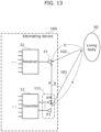
- FIG. 13 is a diagram illustrating an example of a detection target of estimating device 100 illustrated in FIG. 12 .
- Estimation device 100 illustrated in FIG. 12 includes transmission antenna 111, transmitter 12, transmission signal generator 13, reception antenna 21, receiver 22, complex transfer function calculator 123, calibrator 124, living body correlation matrix calculator 125, estimator 126, angle estimator 127, and positioner 128. Estimation device 100 estimates the position of living body 50 using estimating device 100 as a directional or positional reference.
- Transmission antenna 111 includes M (M is at least 2) transmission antenna elements. As described above, the transmission antenna elements transmit a multicarrier signal (transmission wave) generated by transmitter 12 to be described later.
- Transmission signal generator 13 generates a multicarrier signal obtained by modulating a plurality of subcarrier signals for each transmission antenna element included in transmission antenna 111.
- transmission signal generator 13 is exemplified as generating an OFDM signal which has a high frequency band utilization efficiency and consists of S subcarriers.
- other multicarrier signals such as a simple frequency division multiplexing (FDM) signal may be generated as long as it is a multicarrier signal obtainable by multicarrier modulation.
- FDM frequency division multiplexing
- the signal generated by transmission signal generator 13 may be a signal that is shared with a signal used for communication.
- Transmitter 12 adds appropriate processing to the signal generated by transmission signal generator 13, to generate a transmission wave.
- the processing carried out here includes, for example, up-conversion in which the signal is converted from the intermediate frequency (IF) frequency band to the radio frequency (RF) frequency band, amplification in which the signal is amplified to the appropriate transmission level, etc.
- transmitter 12 outputs the processed multicarrier signal to transmission antenna 111 to thereby cause transmission antenna 111 to transmit the multicarrier signal.
- the multicarrier signal is transmitted from the M (M is greater than or equal to 2) transmission antenna elements included in transmission antenna 111.
- Reception antenna 21 includes N reception antenna elements.
- N is a natural number greater than or equal to 1.
- reception antenna 21 includes one reception antenna element. Then, for example, as illustrated in FIG. 13 , the one reception antenna element receives signals that were transmitted by the M transmission antenna elements and reflected by living body 50 (i.e., reception signals).
- Receiver 22 measures, for a first period equivalent to a cycle derived from an activity of living body 50, the reception signals that are received by the single reception antenna element and include reflected signals which are the multicarrier signals transmitted from the M transmission antenna elements that have been reflected or dispersed by living body 50.
- a cycle derived from the activity of the living body is a living body-derived cycle (living body fluctuation cycle) which is a time period greater than or equal to a half-cycle of any of the cycles of respiration, heartbeat, and body motion of living body 50.
- Receiver 22 converts the high-frequency signal received by the single reception antenna element into a low-frequency signal on which signal processing can be performed. Then, receiver 22 demodulates the M OFDM signals transmitted by the M transmission antenna elements into S ⁇ M subcarrier signals. Each of the S ⁇ M subcarrier signals is represented by an IQ symbol. Receiver 22 outputs, to complex transfer function calculator 23, the S ⁇ M sets of subcarrier signals obtained by converting the high-frequency signal received by the N (one in the present embodiment) reception antenna elements, for at least the first period.
- receiver 22 may continue to measure the reception signals already received by reception antenna 21, and continuously or periodically transmit the S ⁇ M subcarrier signals (IQ symbols) to complex transfer function calculator 23.
- Complex transfer function calculator 123 uses the reception signals measured in the first period by receiver 22, calculates, for each of the subcarriers to which the subcarrier signals correspond, a plurality of complex transfer functions indicating propagation characteristics between a transmission antenna element and a reception antenna element in each of M ⁇ N combinations (one combination in the present embodiment) which are the combinations of each of the M (one in the present embodiment) transmission antenna elements and each of the N (one in the present embodiment) reception antenna elements. It should be noted that the M ⁇ N combinations are all the obtainable one-to-one combinations between the M transmission antenna elements and the N reception antenna elements.
- complex transfer function calculator 123 calculates, using the S ⁇ M subcarrier signals transmitted from receiver 22, complex transfer functions indicating the propagation characteristics between each of the transmission antenna elements and each of the reception antenna elements, for each of the S subcarrier signals.
- the calculated complex transfer function matrix also includes reflected waves that did not arrive via living body 50, such as direct waves and reflected waves derived from a fixed object.
- the method of calculating complex transfer functions from one subcarrier signal includes, for example, a method of dividing a reception IQ symbol by a known signal such as a pilot signal or a guard interval signal.
- subcarrier signal S0 which serves as a reference, is used to divide the other subcarrier signals.
- an element that will serve as a reference may be determined, and the complex transfer function matrix at each time point may be normalized (divided) by the element serving as the reference. With this operation, noise arising from the variance between the operation clocks of the transmitter and the receiver can also be removed.
- the element of the complex transfer function that will serve as a reference may be the average of the elements of the complex transfer functions, or may be a direct wave component obtained by Eigendecomposition of a correlation matrix of the complex transfer functions.
- Complex transfer function calculator 123 calculates the complex transfer functions for each of the S subcarrier signals, and outputs the obtained S complex transfer function matrices to calibrator 124.
- complex transfer function calculator 123 may constantly calculate the complex transfer function matrix, either continuously or on a regular basis, using each of the subcarrier signals outputted by receiver 22.
- the complex transfer function matrix that is normally calculated for use in processing by the communication device can also be used by estimating device 100.
- Calibrator 124 obtains the calculated matrix V, and performs calibration for phase error in the frequency direction.
- a phase error in the frequency direction refers to, among differences with respect to the phase of subcarrier signal S0 used as a reference calculated by complex transfer function calculator 123, a phase difference not resulting from spatial propagation between the antennas.
- the phase error includes the influence of the frequency characteristics of transmission antenna 111 and reception antenna 21, the electrical length of the internal circuitry of transmitter 12, the electrical length of the internal circuitry of receiver 22, and so on.
- the phase error includes phase difference e j ⁇ tx caused by transmission antenna 111 and transmitter 12 and phase error e j ⁇ rx caused by reception antenna 21 and receiver 22.
- V v 1 1 ⁇ v 1 S ⁇ ⁇ ⁇ v M 1 ⁇ v MS
- Calibrator 124 performs calibration on each row of matrix V, that is, for each antenna, based on a frequency direction calibration value calculated using a predetermined method.
- calibrator 124 calculates h ideal which is the ideal inter-antenna element channel, based on distance d j between the j-th transmission antenna element and reception antenna element that is inputted in advance.
- h ideal is a vector represented by the complex number
- h ideal has S elements which is the subcarrier number.
- the i-th element is calculated as follows.
- h ideal i exp ⁇ jk i d j
- k i is the wavenumber of the i-th subcarrier.
- h ideal is an ideal complex transfer function between the transmission antenna element and the reception transmission element obtainable based on the inter-antenna distance between the transmission antenna element and the reception transmission element.
- calibrator 124 obtains, from complex transfer function calculator 123, a reference complex transfer function matrix that includes M ⁇ N complex transfer functions measured in a second period, and serves as a reference. It should be noted that measurement of the reference complex transfer function matrix is preferably performed in a person-free state in which there is little influence from a living body, but may include the influence of a living body.
- An initial complex transfer function matrix obtained from complex transfer function calculator 123 may be used for the reference complex transfer function matrix.
- calibrator 124 may calculate a new reference complex transfer function matrix based on data of a timing at which fluctuation obtained by simultaneously calculating the temporal fluctuations of absolute values of complex transfer functions is small, and update the reference complex transfer function matrix with the new reference complex transfer function matrix calculated.
- the reference complex transfer matrix is the matrix h meas having an element number of S ⁇ M.
- calibrator 124 calculates reference matrix V v meas by singular value decomposition in the same manner as the complex transfer function matrix measured in the first period.
- calibrator 124 performs calibration (correction) of matrix V v according to the following equation, based on calibration value v cal .
- v ′ ⁇ v cal ⁇ v
- ⁇ v cal represents the phase angle of v cal .
- ⁇ represents the Hadamard product which is the per element product.
- Calibrator 124 also performs the same correction on the rows of matrix V which correspond to other transmission antennas, and outputs the calibrated matrix V V' to living body correlation matrix calculator 125 and angle estimator 127 located downstream.
- living body correlation matrix calculator 125 For each of the subcarriers and each of the M ⁇ N combinations, living body correlation matrix calculator 125 successively records, in the time-series order in which the reception signals are measured, the plurality of calibrated V matrices calculated by calibrator 124. Then, living body correlation matrix calculator 125 extracts, for each of the subcarriers and each of the M ⁇ N combinations, components of the living body from the calibrated matrix V V' recorded in time series and measured for the first time period, to thereby calculate, for each of the subcarriers, a living body component transfer function matrix expressed by a M ⁇ N-dimension matrix.
- the living body component transfer function matrix is the extracted reflected wave or dispersed wave (living body component) included in the reception signal that passed via living body 50.
- the methods of calculating the living body component from the complex transfer functions recorded in time-series include the method using Fourier transform disclosed in PTL 1 and the method using difference information disclosed in PTL 2.
- living body component matrix V V' fft can be calculated.
- living body component matrix V V' fft is calculated for each of frequency components included in the frequencies, for example, 0.1 Hz to 3 Hz, which can include the influence of activities of the living body.
- the time from when a signal including a living body component is transmitted from the transmitter until it is received by the receiver can be calculated.
- the bandwidth is 20 MHz
- the temporal resolution is equivalent to 0.5 ⁇ s or approximately 15 m when converted to distance resolution, which does not stand up to practical use.
- E[•] in Equation 14 indicates the average arithmetic processing in the frequency direction that may include the influence of the living body, in the column direction, that is, for each transmission antenna, and m indicates the index number from 1 to M of the transmission antennas.
- Estimator 126 performs ranging according to the MUSIC method, using correlation matrix R' f calculated by living body correlation matrix calculator 125. In other words, estimator 126 estimates distance using the MUSIC method. First, estimator 126 performs Eigendecomposition of correlation matrix R' f , and calculates eigenvector US' corresponding to a signal and eigenvector U N ' corresponding to noise.
- eigenvectors corresponding to a signal are the vectors counted in order from a first eigenvector to the number of targets to be ranged, and is, for example, only the first eigenvector when the target is one person.
- the eigenvectors corresponding to a signal are the k eigenvectors from the first eigenvector to the k-th eigenvector.
- eigenvectors corresponding to noise refers to eigenvectors other than the eigenvectors corresponding to a signal.
- a l 1 , e ⁇ j 2 ⁇ ⁇ l , ... , e ⁇ j 2 ⁇ ⁇ l S ⁇ 1 T l which takes the maximum value of MUSIC spectrum P MUSIC (I) obtained in the above manner corresponds to the sum (third distance) of distance a (first distance) between transmission antenna elements and living body 50 and distance b (second distance) between a reception antenna element and living body 50 in FIG. 13 .
- estimator 126 can calculate the third distance by calculating maximum value l.
- estimator 126 estimates the third distance that is the sum of the first distance between transmission antenna 111 and living body 50 and the second distance, by using the living body correlation matrix calculated for each of the plurality of subcarriers.
- Estimator 126 outputs, to positioner 128, the estimated sum of distance a (first distance) between the transmission antenna elements and living body 50 and distance b (second distance) between the reception antenna element and living body 50, as third distance L.
- Angle estimator 127 estimates the angle (direction) in which living body 50 is located when seen from transmission antenna 111 (that is, estimation device 100), using the calibrated matrix V calculated by calibrator 124.
- incoming angle estimation using the MUSIC method described in PTL 1 can be used for the estimation. It should be noted that although the angle from a transmission antenna element is estimated in the present embodiment, a device including a plurality of reception antenna elements may be used and the angle from a reception antenna element may be estimated.
- Angle estimator 127 transmits, to positioner 128, first angle ⁇ which is the estimated angle in which living body 50 is located.
- Positioner 128 estimates the coordinates of living body 50, based on third distance L estimated by estimator 126 and first angle ⁇ estimated by angle estimator 127.
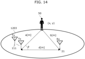
- FIG. 14 illustrates the relationship between living body 50, transmission antenna 111, reception antenna 21, third distance L, and first angle ⁇ .
- third distance L equivalent to the sum of first distance a and second distance b in FIG. 14 is defined, it is understood that the position of living body 50 is on the circumference of ellipse 1203, and, since first angle ⁇ which is the angle from transmission antenna 111 is also defined, the position of living body 50 is determined to be at one point on the circumference of ellipse 1203.
- first angle ⁇ which is the angle from transmission antenna 111
- positioner 128 calculates first distance a based on the law of cosines, using third distance L, first angle ⁇ , and inter-antenna distance d.
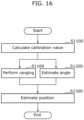
- FIG. 16 is a flowchart illustrating the estimation process by estimating device 100 according to Embodiment 2.
- Estimation device 100 first calculates the calibration value (S1000).
- estimation device 100 performs ranging for third distance L based on the calculated calibration value (S1100).
- estimation device 100 estimates first angle ⁇ which is the angle of living body 50 with respect to estimation device 100, in parallel with or before or after the ranging (S1200).
- estimation device 100 estimates the position of living body 50 based on third distance L and first distance ⁇ (S1300). Since the processing in each step has been previously described, description will be omitted.
- the coordinates of a living body can be estimated even when using an estimating device having a MISO or SIMO configuration.
- the present disclosure can realize an estimating device and an estimating method that are capable of quickly and accurately estimating the distance or position of a living body by using radio signals.
- the present disclosure is not limited to living body 50.
- the present disclosure can be applied to various moving bodies (machines, etc.) whose activity imparts a Doppler effect on reflected waves in the case where a high-frequency signal is emitted.
- the present disclosure can be realized, not only as a positioning sensor including the above-described characteristic structural elements, but also as an estimating method including, as steps, the characteristic structural elements included in the positioning sensor.
- the present invention can also be realized as a computer program that causes a computer to execute the respective steps included in such a method.
- a program can be distributed via a non-transitory computer-readable recording medium such as CD-ROM or a communication network such as the Internet.
- the present disclosure can be used in a positioning sensor and a distance estimating method for estimating the distance or position of a living body by using radio signals, and can be used particularly in a ranging sensor and a direction estimating method provided to a measuring device that measures the distance or position of a living body including a living body and a machine, a household appliance that performs control according to the distance or position of a living body, a monitoring device that detects incursion of a living body, and so on.
Landscapes
- Engineering & Computer Science (AREA)
- Radar, Positioning & Navigation (AREA)
- Remote Sensing (AREA)
- Computer Networks & Wireless Communication (AREA)
- Physics & Mathematics (AREA)
- General Physics & Mathematics (AREA)
- Radar Systems Or Details Thereof (AREA)
Applications Claiming Priority (2)
| Application Number | Priority Date | Filing Date | Title |
|---|---|---|---|
| JP2021212607 | 2021-12-27 | ||
| PCT/JP2022/042775 WO2023127340A1 (ja) | 2021-12-27 | 2022-11-17 | 推定装置、推定方法及びプログラム |
Publications (2)
| Publication Number | Publication Date |
|---|---|
| EP4459322A1 true EP4459322A1 (de) | 2024-11-06 |
| EP4459322A4 EP4459322A4 (de) | 2025-04-30 |
Family
ID=86998836
Family Applications (1)
| Application Number | Title | Priority Date | Filing Date |
|---|---|---|---|
| EP22915571.8A Pending EP4459322A4 (de) | 2021-12-27 | 2022-11-17 | Schätzvorrichtung, schätzverfahren und programm |
Country Status (5)
| Country | Link |
|---|---|
| US (1) | US20250060468A1 (de) |
| EP (1) | EP4459322A4 (de) |
| JP (1) | JP7653624B2 (de) |
| CN (1) | CN118414558A (de) |
| WO (1) | WO2023127340A1 (de) |
Families Citing this family (1)
| Publication number | Priority date | Publication date | Assignee | Title |
|---|---|---|---|---|
| WO2026004758A1 (ja) * | 2024-06-26 | 2026-01-02 | パナソニックIpマネジメント株式会社 | 推定装置、推定方法及びプログラム |
Family Cites Families (12)
| Publication number | Priority date | Publication date | Assignee | Title |
|---|---|---|---|---|
| CN101572581A (zh) | 2008-04-29 | 2009-11-04 | 株式会社Ntt都科摩 | 一种信干噪比确定方法及装置 |
| JP2012004668A (ja) | 2010-06-14 | 2012-01-05 | Sony Corp | 頭部伝達関数生成装置、頭部伝達関数生成方法及び音声信号処理装置 |
| JP2012088279A (ja) | 2010-10-22 | 2012-05-10 | Mitsubishi Electric Corp | レーダ装置、およびレーダ装置に適用される移動目標検出方法 |
| JP5704695B2 (ja) | 2010-12-24 | 2015-04-22 | 大学共同利用機関法人情報・システム研究機構 | ドップラーレーダーシステム、ドップラーレーダー送信装置及び送信波最適化方法 |
| JP6402398B2 (ja) | 2013-12-17 | 2018-10-10 | 三星電子株式会社Samsung Electronics Co.,Ltd. | 処理装置、および処理方法 |
| JP6396073B2 (ja) | 2014-05-21 | 2018-09-26 | 国立研究開発法人情報通信研究機構 | 信号伝搬特性の測定法 |
| JP6504546B2 (ja) | 2016-01-15 | 2019-04-24 | パナソニックIpマネジメント株式会社 | 推定装置および推定方法 |
| JP6667145B2 (ja) | 2016-07-05 | 2020-03-18 | パナソニックIpマネジメント株式会社 | センサーおよび推定方法 |
| JP6716435B2 (ja) * | 2016-11-21 | 2020-07-01 | 株式会社東芝 | レーダシステム及びそのレーダ信号処理方法 |
| JP6587199B1 (ja) * | 2018-07-03 | 2019-10-09 | パナソニックIpマネジメント株式会社 | 推定装置および推定方法 |
| JP7357217B2 (ja) * | 2018-12-28 | 2023-10-06 | パナソニックIpマネジメント株式会社 | 推定方法、推定装置、及び、プログラム |
| US11255955B2 (en) * | 2018-12-28 | 2022-02-22 | Panasonic Intellectual Property Management Co., Ltd. | Estimation method, estimation device, and recording medium |
-
2022
- 2022-11-17 JP JP2023570725A patent/JP7653624B2/ja active Active
- 2022-11-17 WO PCT/JP2022/042775 patent/WO2023127340A1/ja not_active Ceased
- 2022-11-17 CN CN202280084151.2A patent/CN118414558A/zh active Pending
- 2022-11-17 EP EP22915571.8A patent/EP4459322A4/de active Pending
- 2022-11-17 US US18/721,546 patent/US20250060468A1/en active Pending
Also Published As
| Publication number | Publication date |
|---|---|
| JPWO2023127340A1 (de) | 2023-07-06 |
| JP7653624B2 (ja) | 2025-03-31 |
| CN118414558A (zh) | 2024-07-30 |
| US20250060468A1 (en) | 2025-02-20 |
| EP4459322A4 (de) | 2025-04-30 |
| WO2023127340A1 (ja) | 2023-07-06 |
Similar Documents
| Publication | Publication Date | Title |
|---|---|---|
| Hakobyan et al. | A novel intercarrier-interference free signal processing scheme for OFDM radar | |
| JP6832534B2 (ja) | 推定装置および推定方法 | |
| EP1970728B1 (de) | DSSS-Radar, mittels Radar implementiertes Verfahren und computerlesbares Speichermedium | |
| US20160041260A1 (en) | Radar apparatus and object sensing method | |
| JP5089460B2 (ja) | 伝搬遅延時間測定装置及びレーダ装置 | |
| US12019141B2 (en) | Radar processor | |
| JP2012194051A (ja) | 電子走査型レーダ装置、受信波方向推定方法及びプログラム | |
| Schweizer et al. | Mutual interference of automotive OFDM radars—Analysis and countermeasures | |
| EP4459322A1 (de) | Schätzvorrichtung, schätzverfahren und programm | |
| Bhattacharjee et al. | Multi-carrier wideband OCDM-based THz automotive radar | |
| Shi et al. | Modified Cramér-Rao lower bounds for joint position and velocity estimation of a Rician target in OFDM-based passive radar networks | |
| Han et al. | A new high precise indoor localization approach using single access point | |
| JP5354126B2 (ja) | 直接シーケンススペクトル拡散方式のレーダー | |
| JP7769942B2 (ja) | 推定装置、推定方法及びプログラム | |
| JP7796342B2 (ja) | 推定装置、推定方法、及び、プログラム | |
| Rong et al. | OFDM Based Joint Communications and Human Activity Monitoring with GNU Radio | |
| Chang et al. | The estimation method of multi-target parameters for OTFS radar sensing | |
| Meinaassner et al. | Near Range, Leakage Aware Object Localization Based on 5G NR-Compliant JCAS | |
| JP7801675B2 (ja) | 推定装置、推定方法及びプログラム | |
| Yildirim et al. | High resolution 802.11 ax-based passive radar for human movement monitoring | |
| EP4365621A1 (de) | Schätzverfahren und schätzvorrichtung | |
| Muth et al. | Improved Estimation Accuracy in OFDM-Based Joint Communication and Sensing Through Kalman Tracking and Interpolation | |
| Kulhandjian et al. | Detection and Parameter Estimation of Pulsed LFM Radar for Opportunistic Resource Sharing in Radar-Cellular Coexistence | |
| Zhao et al. | A Multi-channel Target Detection Algorithm Based on OFDM Communication Signal | |
| WO2025009427A1 (ja) | 推定装置、推定方法及びプログラム |
Legal Events
| Date | Code | Title | Description |
|---|---|---|---|
| STAA | Information on the status of an ep patent application or granted ep patent |
Free format text: STATUS: THE INTERNATIONAL PUBLICATION HAS BEEN MADE |
|
| PUAI | Public reference made under article 153(3) epc to a published international application that has entered the european phase |
Free format text: ORIGINAL CODE: 0009012 |
|
| STAA | Information on the status of an ep patent application or granted ep patent |
Free format text: STATUS: REQUEST FOR EXAMINATION WAS MADE |
|
| 17P | Request for examination filed |
Effective date: 20240610 |
|
| AK | Designated contracting states |
Kind code of ref document: A1 Designated state(s): AL AT BE BG CH CY CZ DE DK EE ES FI FR GB GR HR HU IE IS IT LI LT LU LV MC ME MK MT NL NO PL PT RO RS SE SI SK SM TR |
|
| REG | Reference to a national code |
Ref country code: DE Ref legal event code: R079 Free format text: PREVIOUS MAIN CLASS: G01S0013320000 Ipc: G01S0007410000 |
|
| DAV | Request for validation of the european patent (deleted) | ||
| DAX | Request for extension of the european patent (deleted) | ||
| A4 | Supplementary search report drawn up and despatched |
Effective date: 20250326 |
|
| RIC1 | Information provided on ipc code assigned before grant |
Ipc: G01S 7/40 20060101ALI20250321BHEP Ipc: G01S 13/46 20060101ALI20250321BHEP Ipc: G01S 13/34 20060101ALI20250321BHEP Ipc: G01S 13/00 20060101ALI20250321BHEP Ipc: G01S 7/41 20060101AFI20250321BHEP |