EP4459293A1 - Stromwandlermodul - Google Patents
Stromwandlermodul Download PDFInfo
- Publication number
- EP4459293A1 EP4459293A1 EP23171954.3A EP23171954A EP4459293A1 EP 4459293 A1 EP4459293 A1 EP 4459293A1 EP 23171954 A EP23171954 A EP 23171954A EP 4459293 A1 EP4459293 A1 EP 4459293A1
- Authority
- EP
- European Patent Office
- Prior art keywords
- housing
- magnetic field
- current transducer
- core part
- primary conductor
- Prior art date
- Legal status (The legal status is an assumption and is not a legal conclusion. Google has not performed a legal analysis and makes no representation as to the accuracy of the status listed.)
- Granted
Links
Images


Classifications
-
- G—PHYSICS
- G01—MEASURING; TESTING
- G01R—MEASURING ELECTRIC VARIABLES; MEASURING MAGNETIC VARIABLES
- G01R15/00—Details of measuring arrangements of the types provided for in groups G01R17/00 - G01R29/00, G01R33/00 - G01R33/26 or G01R35/00
- G01R15/14—Adaptations providing voltage or current isolation, e.g. for high-voltage or high-current networks
- G01R15/20—Adaptations providing voltage or current isolation, e.g. for high-voltage or high-current networks using galvano-magnetic devices, e.g. Hall-effect devices, i.e. measuring a magnetic field via the interaction between a current and a magnetic field, e.g. magneto resistive or Hall effect devices
- G01R15/207—Constructional details independent of the type of device used
Definitions
- the present invention relates to an open loop current transducer module for mounting on a primary conductor unit.
- Many conventional open loop current transducers comprise a magnetic core with an air gap in which a magnetic field detector is positioned for measuring a magnetic field induced by a primary conductor carrying a current to be measured by the magnetic core.
- Such open loop type of current transducers are widely used in current sensing applications in view of their durability, large current measuring range and low cost, in particular including the low cost of the electronics required to drive the current transducer circuit.
- the primary conductor bar forms part of the transducer and has connection ends configured to be connected to a conductor carrying the current to be measured.
- the integration of the primary conductor in the transducer facilitates installation and connection of the transducer to the system in which it is implemented to measure a primary current.
- Integration of the primary conductor bar in the current transducer also avoids a more complex current transducer arrangement requiring a split magnetic core, for instance mounted in a two-part hinge coupled housing that can be assembled around a primary conductor bar. It however has drawbacks in that it increases the overall size of the arrangement current transducer and external system to which the current transducer is coupled.
- the additional interconnections between the primary conductor bar section and the external circuit are also sources of potential problems especially in harsh environments with vibration, and mechanical and thermally caused stresses.
- a specific object of the invention is to provide a compact yet robust, durable and reliable open loop current transducer for measuring currents in a power inverter, in particular for electric motor drives, for instance electrical motors for automotive applications, that is economical to produce and install.
- the current transducer should be able to operate in a current measurement range of up to 1000 A.
- a current transducer module comprising
- the magnetic field detectors are mounted on a first primary conductor facing side of the circuit board and the magnetic core part is mounted on a second side of the circuit board, opposite the first primary conductor facing side.
- the housing further comprises locating ribs upstanding from the base wall within the internal cavity, upper edges of the locating ribs positioned against the magnetic core part.
- the circuit board comprises slots receiving the locating ribs therethrough.
- the magnetic core part comprises a substantially linear beam portion and at each core end a transverse projecting stub portion.
- the housing comprises one or more locating elements protruding outwardly from one or more lateral sides of the housing.
- the locating ribs comprise at least one locating rib on each of at least three side walls of the housing.
- the housing comprises a base portion including the base wall and the side walls, and a cover portion separately formed from the base portion and configured to be assembled to the base portion to close the internal cavity.
- the current transducer module further comprises electrical contacts connected to the circuit board and extending from the circuit board through the top wall for connection to external contacts.
- the current transducer module is configured for mounting on a primary conductor module comprising a housing, a primary conductor bar lodged partially within the housing, and a magnetic core part mounted in the housing adjacent a first side of the primary conductor bar such that the magnetic core part of the primary conductor module and the magnetic core part of the current transducer module surround the primary conductor bar and define airgaps in which the magnetic field detectors are positioned.
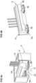
- a current transducer module 2 configured to be assembled to a primary conductor module 1 of an external system, such as a power inverter for an electrical drive, is illustrated.
- the primary conductor module 1 comprises a housing 5, a primary conductor bar 3 carrying a primary current for instance powered by a power inverter for supplying a phase current to an electrical motor.
- the primary conductor module may comprise a circuit board (not shown) and contacts 9 for power and signal communication with electronic components on the circuit board of the primary conductor module 1.
- the primary conductor module 1 further comprises a magnetic core part 7 positioned adjacent a first side 17a of the primary conductor bar 3, opposite a second side 17b of the primary conductor bar 3 facing an interface surface configured for receiving the current transducer module 2.
- the primary conductor bar 3 may have a substantially rectangular cross-section with a width W and a height H , with first and second opposed major surfaces defining above mentioned first and second sides 17a, 17b, and third and fourth opposed minor surfaces 17c.
- the current transducer module 2 comprises a housing defining an internal cavity 28, and a magnetic core part 6, magnetic field detectors 8a, 8b, and a circuit board 10 mounted in the internal cavity 28.
- the housing 4 has an outer primary conductor mounting side 12, a top wall side 14, and lateral sides 16 joining the top wall side to the primary conductor mounting side 12.
- the primary conductor mounting side 12 is configured to be mounted against a transducer receiving side 11 of the primary conductor module 1.
- the transducer receiving side 11 may advantageously be recessed relative to an outer surface 13 of the primary conductor module 1 such that the current transducer module 2 is partially inserted into the recess when assembled to the primary conductor module 1.
- the recess is surrounded by a recess side wall 15 having a perimeter with the shape of the perimeter of the primary conductor mounting side 12 of the current transducer module 2.
- the primary conductor mounting side 12 of the current transducer module has a flat portion in a mounting plane M parallel or substantially parallel to the plane of the second side of the primary conductor bar 3 when the current transducer module 2 is assembled to the primary conductor module 1.
- the magnetic field detectors 8a, 8b comprise first and second magnetic field detectors mounted on the circuit board 10 in a spaced apart relationship with the spacing corresponding substantially to the width W of the primary conductor bar 3. Each magnetic field detector 8a, 8b is thus configured to be positioned approximately adjacent a corresponding minor side 17c of primary conductor bar 3.
- the magnetic core part 6 comprises a substantially linear beam shape extending between first and second ends, each end overlying a corresponding one of the magnetic field detectors 8a, 8b.
- the magnetic core may comprise short stubs 6a, 6b extending from each end towards the corresponding magnetic field detector such that the magnetic core part forms a flat "U" shaped part.
- the magnetic field detectors are mounted on a first side, forming a primary conductor facing side 38 of the circuit board 10, and the magnetic core part is mounted on the opposite second side 40 of the circuit board 10.
- the circuit may be provided with further electrical or electronic components (not shown) and comprise contacts 34 for signal and power interconnection to the circuit board including the magnetic field detectors 8a, 8b.
- the magnetic field detectors 8a, 8b may be in the form of ASICs (Application Specific Integrated Circuits) comprising for instance Hall effect magnetic field detector as per se well known in the art of current transducers.
- ASICs Application Specific Integrated Circuits
- the housing 4 may comprise locating ribs 30 formed in the internal cavity 28 upstanding from a base wall 24 of the housing, the locating ribs 30 having an upper edge 31 adjacent the magnetic core part 6 and against which the magnetic core part 6 may rest and be positioned.
- the locating ribs 30 may thus serve as positioning elements that accurately position the core ends 6a, 6b of the magnetic core part 6 relative to the base wall 24 and thus to the primary conductor mounting side surface 12 of the housing 4. This ensures a calibrated accurate airgap distance formed between the magnetic core part core ends 6a, 6b and the core ends 7a, 7b of the magnetic core part 7 in the primary conductor module 1 when the current transducer module is placed against the transducer receiving side 11 of the primary conductor module 1.
- the circuit board 10 is provided with corresponding slots 36 for receiving the locating elements 20 therethrough.
- the position of the circuit board 10 relative to the base wall 24 of the housing may be provided by one or more protuberances upstanding from the base wall configured to provide a gap between the first side 38 of the circuit board and the base wall 24 to fit the thickness of the magnetic field detectors 8a, 8b.
- the magnetic field detectors in the form of ASICs are thus sandwiched between the circuit board 10 and the housing base wall 24.
- the core ends 6a, 6b of the magnetic core part 6 and the magnetic field detectors 8a, 8b are positioned substantially opposite and facing the magnetic core part ends 7a, 7b of the magnetic core part 7 mounted in the primary conductor module 1.
- the magnetic field detectors 8a, 8b are thus positioned in airgaps formed by the two magnetic core parts 6, 7 when the current transducer module 2 is assembled to the primary conductor module 1, the magnetic core parts 7, 6 surrounding the primary conductor bar 3.
- the housing 4 of the current transducer module advantageously comprises locating elements 20 formed on one or more lateral sides 16 cooperating with complementary locating elements 21 formed on a corresponding one or more lateral sides of the recess side wall 15 of the housing 5 of the primary conductor module 1.
- the locating elements 20 may for instance be in the form of protuberances (flanges, ribs) extending outwardly from the lateral sides 16, engaging in complementary cavities or slots formed in the recess side wall 15 of the primary conductor module housing 5.
- the locating elements 20 serve to ensure correct assembly and accurate registration of the current transducer module 2 to the primary conductor module 1 when the two parts are assembled together.
- the current transducer module may further be provided with mounting posts 18 extending from the primary conductor mounting side 12 of the base wall 24 for insertion in corresponding mounting holes in the receiving side 11 of the primary conductor module housing 5.
- the current transducer module 2 may be welded, adhesively bonded, or fixed by screws or other mechanical fixing means to the primary conductor module 1 once assembled thereto.
- the housing 4 of the current transducer module may advantageously be provided in two parts comprising a base portion 4a including the base wall 24 and side walls 26 upstanding therefrom defining the internal cavity 28, and a cover portion 4b that mounts to the base portion to close the internal cavity 28, the cover portion 4b forming a top wall 14.
- the housing 4 may be provided without a cover part, and the internal cavity 28 filled with an insulating potting material, or even without a potting material, simply covered by an external unit that mounts over the top of the transducer module and connects to the contacts 34.
- the cover portion 4b may be provided with orifices to receive the contacts 34 therethrough for plugging connection or for solder or weld connection to contacts of an external circuit, for instance an external circuit board that may be mounted against the top wall 14 of the housing.
- the contacts 9 of the primary conductor module 1 may be connected to the same external circuit board as the contacts 34 of the current transducer module 2.
- the circuit board may be arranged upstanding with respect to the base wall 42 and the core ends 6a, 6b facing directly adjacent the magnetic field detectors 8a, 8b such that the magnetic field detectors are positioned in a gap between the housing base wall and the magnetic core part without the circuit board therebetween.
- the housing 4 of the current transducer module of figure 4a also comprises locating elements (not visible in the cut-away perspective view) formed on one or more lateral sides similar to the first described embodiment.
Landscapes
- Physics & Mathematics (AREA)
- General Physics & Mathematics (AREA)
- Measuring Instrument Details And Bridges, And Automatic Balancing Devices (AREA)
Priority Applications (3)
| Application Number | Priority Date | Filing Date | Title |
|---|---|---|---|
| EP23171954.3A EP4459293B1 (de) | 2023-05-05 | 2023-05-05 | Stromwandlermodul |
| PCT/EP2024/061998 WO2024231198A1 (en) | 2023-05-05 | 2024-05-01 | Current transducer module |
| CN202480030081.1A CN121039502A (zh) | 2023-05-05 | 2024-05-01 | 电流传感器模块 |
Applications Claiming Priority (1)
| Application Number | Priority Date | Filing Date | Title |
|---|---|---|---|
| EP23171954.3A EP4459293B1 (de) | 2023-05-05 | 2023-05-05 | Stromwandlermodul |
Publications (3)
| Publication Number | Publication Date |
|---|---|
| EP4459293A1 true EP4459293A1 (de) | 2024-11-06 |
| EP4459293C0 EP4459293C0 (de) | 2025-08-20 |
| EP4459293B1 EP4459293B1 (de) | 2025-08-20 |
Family
ID=86330266
Family Applications (1)
| Application Number | Title | Priority Date | Filing Date |
|---|---|---|---|
| EP23171954.3A Active EP4459293B1 (de) | 2023-05-05 | 2023-05-05 | Stromwandlermodul |
Country Status (3)
| Country | Link |
|---|---|
| EP (1) | EP4459293B1 (de) |
| CN (1) | CN121039502A (de) |
| WO (1) | WO2024231198A1 (de) |
Citations (4)
| Publication number | Priority date | Publication date | Assignee | Title |
|---|---|---|---|---|
| WO2012137389A1 (ja) * | 2011-04-06 | 2012-10-11 | 東光東芝メーターシステムズ株式会社 | 電流検出装置および電力量計 |
| EP3306325A1 (de) * | 2016-10-05 | 2018-04-11 | Fico Triad, S.A. | Strommessvorrichtung |
| KR20210085664A (ko) * | 2019-12-31 | 2021-07-08 | 주식회사 아모그린텍 | 홀센서 타입 전류센서 및 그의 제조방법 |
| US20220229093A1 (en) * | 2019-10-08 | 2022-07-21 | Alps Alpine Co., Ltd. | Current detection device |
Family Cites Families (4)
| Publication number | Priority date | Publication date | Assignee | Title |
|---|---|---|---|---|
| EP2682762A1 (de) * | 2012-07-06 | 2014-01-08 | Senis AG | Stromwandler zum Messen von Strom, magnetischer Wandler und Stromleckagenerkennungssystem und -verfahren |
| EP2741091A1 (de) * | 2012-12-07 | 2014-06-11 | LEM Intellectual Property SA | Mess-Stromwandler mit Erdungsvorrichtung |
| EP3159705A1 (de) * | 2015-10-23 | 2017-04-26 | LEM Intellectual Property SA | Stromwandler mit integriertem primärem leiter |
| CN114264864A (zh) * | 2022-03-01 | 2022-04-01 | 北京智芯微电子科技有限公司 | 一种电流检测器和电路 |
-
2023
- 2023-05-05 EP EP23171954.3A patent/EP4459293B1/de active Active
-
2024
- 2024-05-01 WO PCT/EP2024/061998 patent/WO2024231198A1/en not_active Ceased
- 2024-05-01 CN CN202480030081.1A patent/CN121039502A/zh active Pending
Patent Citations (4)
| Publication number | Priority date | Publication date | Assignee | Title |
|---|---|---|---|---|
| WO2012137389A1 (ja) * | 2011-04-06 | 2012-10-11 | 東光東芝メーターシステムズ株式会社 | 電流検出装置および電力量計 |
| EP3306325A1 (de) * | 2016-10-05 | 2018-04-11 | Fico Triad, S.A. | Strommessvorrichtung |
| US20220229093A1 (en) * | 2019-10-08 | 2022-07-21 | Alps Alpine Co., Ltd. | Current detection device |
| KR20210085664A (ko) * | 2019-12-31 | 2021-07-08 | 주식회사 아모그린텍 | 홀센서 타입 전류센서 및 그의 제조방법 |
Also Published As
| Publication number | Publication date |
|---|---|
| EP4459293C0 (de) | 2025-08-20 |
| CN121039502A (zh) | 2025-11-28 |
| EP4459293B1 (de) | 2025-08-20 |
| WO2024231198A1 (en) | 2024-11-14 |
Similar Documents
| Publication | Publication Date | Title |
|---|---|---|
| US10126327B2 (en) | Current transducer | |
| US12078661B2 (en) | Current transducer with magnetic field detector module | |
| EP2660611A1 (de) | Elektrisches Stromtransformatormodul | |
| CN103201637A (zh) | 电流检测装置 | |
| US11994538B2 (en) | Current transducer with magnetic core on primary conductor bar | |
| CN116529612B (zh) | 电流传感器 | |
| JP2009150654A (ja) | 電流センサ | |
| EP4459293B1 (de) | Stromwandlermodul | |
| CN120826613A (zh) | 具有差分磁场换能器的电流传感器 | |
| CN116960858A (zh) | 电接线盒 | |
| JP2013217866A (ja) | 電気接続箱及び電流センサ | |
| US12320828B2 (en) | Magnetic field detector module | |
| US11493539B2 (en) | Current transducer | |
| WO2025131825A1 (en) | Coreless current transducer | |
| JP2025059680A (ja) | モータ制御装置 |
Legal Events
| Date | Code | Title | Description |
|---|---|---|---|
| PUAI | Public reference made under article 153(3) epc to a published international application that has entered the european phase |
Free format text: ORIGINAL CODE: 0009012 |
|
| STAA | Information on the status of an ep patent application or granted ep patent |
Free format text: STATUS: THE APPLICATION HAS BEEN PUBLISHED |
|
| AK | Designated contracting states |
Kind code of ref document: A1 Designated state(s): AL AT BE BG CH CY CZ DE DK EE ES FI FR GB GR HR HU IE IS IT LI LT LU LV MC ME MK MT NL NO PL PT RO RS SE SI SK SM TR |
|
| STAA | Information on the status of an ep patent application or granted ep patent |
Free format text: STATUS: REQUEST FOR EXAMINATION WAS MADE |
|
| 17P | Request for examination filed |
Effective date: 20241202 |
|
| RBV | Designated contracting states (corrected) |
Designated state(s): AL AT BE BG CH CY CZ DE DK EE ES FI FR GB GR HR HU IE IS IT LI LT LU LV MC ME MK MT NL NO PL PT RO RS SE SI SK SM TR |
|
| GRAP | Despatch of communication of intention to grant a patent |
Free format text: ORIGINAL CODE: EPIDOSNIGR1 |
|
| STAA | Information on the status of an ep patent application or granted ep patent |
Free format text: STATUS: GRANT OF PATENT IS INTENDED |
|
| INTG | Intention to grant announced |
Effective date: 20250225 |
|
| GRAS | Grant fee paid |
Free format text: ORIGINAL CODE: EPIDOSNIGR3 |
|
| GRAA | (expected) grant |
Free format text: ORIGINAL CODE: 0009210 |
|
| STAA | Information on the status of an ep patent application or granted ep patent |
Free format text: STATUS: THE PATENT HAS BEEN GRANTED |
|
| AK | Designated contracting states |
Kind code of ref document: B1 Designated state(s): AL AT BE BG CH CY CZ DE DK EE ES FI FR GB GR HR HU IE IS IT LI LT LU LV MC ME MK MT NL NO PL PT RO RS SE SI SK SM TR |
|
| REG | Reference to a national code |
Ref country code: GB Ref legal event code: FG4D |
|
| REG | Reference to a national code |
Ref country code: CH Ref legal event code: EP |
|
| REG | Reference to a national code |
Ref country code: DE Ref legal event code: R096 Ref document number: 602023005805 Country of ref document: DE |
|
| REG | Reference to a national code |
Ref country code: IE Ref legal event code: FG4D |
|
| U01 | Request for unitary effect filed |
Effective date: 20250910 |
|
| U07 | Unitary effect registered |
Designated state(s): AT BE BG DE DK EE FI FR IT LT LU LV MT NL PT RO SE SI Effective date: 20250915 |
|
| PG25 | Lapsed in a contracting state [announced via postgrant information from national office to epo] |
Ref country code: IS Free format text: LAPSE BECAUSE OF FAILURE TO SUBMIT A TRANSLATION OF THE DESCRIPTION OR TO PAY THE FEE WITHIN THE PRESCRIBED TIME-LIMIT Effective date: 20251220 |
|
| PG25 | Lapsed in a contracting state [announced via postgrant information from national office to epo] |
Ref country code: NO Free format text: LAPSE BECAUSE OF FAILURE TO SUBMIT A TRANSLATION OF THE DESCRIPTION OR TO PAY THE FEE WITHIN THE PRESCRIBED TIME-LIMIT Effective date: 20251120 |
|
| PG25 | Lapsed in a contracting state [announced via postgrant information from national office to epo] |
Ref country code: HR Free format text: LAPSE BECAUSE OF FAILURE TO SUBMIT A TRANSLATION OF THE DESCRIPTION OR TO PAY THE FEE WITHIN THE PRESCRIBED TIME-LIMIT Effective date: 20250820 |
|
| PG25 | Lapsed in a contracting state [announced via postgrant information from national office to epo] |
Ref country code: GR Free format text: LAPSE BECAUSE OF FAILURE TO SUBMIT A TRANSLATION OF THE DESCRIPTION OR TO PAY THE FEE WITHIN THE PRESCRIBED TIME-LIMIT Effective date: 20251121 |
|
| PG25 | Lapsed in a contracting state [announced via postgrant information from national office to epo] |
Ref country code: PL Free format text: LAPSE BECAUSE OF FAILURE TO SUBMIT A TRANSLATION OF THE DESCRIPTION OR TO PAY THE FEE WITHIN THE PRESCRIBED TIME-LIMIT Effective date: 20250820 |
|
| PG25 | Lapsed in a contracting state [announced via postgrant information from national office to epo] |
Ref country code: RS Free format text: LAPSE BECAUSE OF FAILURE TO SUBMIT A TRANSLATION OF THE DESCRIPTION OR TO PAY THE FEE WITHIN THE PRESCRIBED TIME-LIMIT Effective date: 20251120 |
|
| PG25 | Lapsed in a contracting state [announced via postgrant information from national office to epo] |
Ref country code: ES Free format text: LAPSE BECAUSE OF FAILURE TO SUBMIT A TRANSLATION OF THE DESCRIPTION OR TO PAY THE FEE WITHIN THE PRESCRIBED TIME-LIMIT Effective date: 20250820 |
|
| PG25 | Lapsed in a contracting state [announced via postgrant information from national office to epo] |
Ref country code: SM Free format text: LAPSE BECAUSE OF FAILURE TO SUBMIT A TRANSLATION OF THE DESCRIPTION OR TO PAY THE FEE WITHIN THE PRESCRIBED TIME-LIMIT Effective date: 20250820 |
|
| PG25 | Lapsed in a contracting state [announced via postgrant information from national office to epo] |
Ref country code: CZ Free format text: LAPSE BECAUSE OF FAILURE TO SUBMIT A TRANSLATION OF THE DESCRIPTION OR TO PAY THE FEE WITHIN THE PRESCRIBED TIME-LIMIT Effective date: 20250820 |
|
| PG25 | Lapsed in a contracting state [announced via postgrant information from national office to epo] |
Ref country code: SK Free format text: LAPSE BECAUSE OF FAILURE TO SUBMIT A TRANSLATION OF THE DESCRIPTION OR TO PAY THE FEE WITHIN THE PRESCRIBED TIME-LIMIT Effective date: 20250820 |
|
| U20 | Renewal fee for the european patent with unitary effect paid |
Year of fee payment: 4 Effective date: 20260319 |