EP4459210A2 - Kühlschrank mit einem trimmschalter mit verstärkungsrippen - Google Patents
Kühlschrank mit einem trimmschalter mit verstärkungsrippen Download PDFInfo
- Publication number
- EP4459210A2 EP4459210A2 EP24201109.6A EP24201109A EP4459210A2 EP 4459210 A2 EP4459210 A2 EP 4459210A2 EP 24201109 A EP24201109 A EP 24201109A EP 4459210 A2 EP4459210 A2 EP 4459210A2
- Authority
- EP
- European Patent Office
- Prior art keywords
- ribs
- trim breaker
- outer rim
- rib
- inner edge
- Prior art date
- Legal status (The legal status is an assumption and is not a legal conclusion. Google has not performed a legal analysis and makes no representation as to the accuracy of the status listed.)
- Pending
Links
Images



Classifications
-
- F—MECHANICAL ENGINEERING; LIGHTING; HEATING; WEAPONS; BLASTING
- F25—REFRIGERATION OR COOLING; COMBINED HEATING AND REFRIGERATION SYSTEMS; HEAT PUMP SYSTEMS; MANUFACTURE OR STORAGE OF ICE; LIQUEFACTION SOLIDIFICATION OF GASES
- F25D—REFRIGERATORS; COLD ROOMS; ICE-BOXES; COOLING OR FREEZING APPARATUS NOT OTHERWISE PROVIDED FOR
- F25D11/00—Self-contained movable devices, e.g. domestic refrigerators
- F25D11/02—Self-contained movable devices, e.g. domestic refrigerators with cooling compartments at different temperatures
-
- F—MECHANICAL ENGINEERING; LIGHTING; HEATING; WEAPONS; BLASTING
- F25—REFRIGERATION OR COOLING; COMBINED HEATING AND REFRIGERATION SYSTEMS; HEAT PUMP SYSTEMS; MANUFACTURE OR STORAGE OF ICE; LIQUEFACTION SOLIDIFICATION OF GASES
- F25D—REFRIGERATORS; COLD ROOMS; ICE-BOXES; COOLING OR FREEZING APPARATUS NOT OTHERWISE PROVIDED FOR
- F25D23/00—General constructional features
- F25D23/08—Parts formed wholly or mainly of plastics materials
- F25D23/082—Strips
- F25D23/085—Breaking strips
-
- F—MECHANICAL ENGINEERING; LIGHTING; HEATING; WEAPONS; BLASTING
- F25—REFRIGERATION OR COOLING; COMBINED HEATING AND REFRIGERATION SYSTEMS; HEAT PUMP SYSTEMS; MANUFACTURE OR STORAGE OF ICE; LIQUEFACTION SOLIDIFICATION OF GASES
- F25D—REFRIGERATORS; COLD ROOMS; ICE-BOXES; COOLING OR FREEZING APPARATUS NOT OTHERWISE PROVIDED FOR
- F25D23/00—General constructional features
-
- F—MECHANICAL ENGINEERING; LIGHTING; HEATING; WEAPONS; BLASTING
- F25—REFRIGERATION OR COOLING; COMBINED HEATING AND REFRIGERATION SYSTEMS; HEAT PUMP SYSTEMS; MANUFACTURE OR STORAGE OF ICE; LIQUEFACTION SOLIDIFICATION OF GASES
- F25D—REFRIGERATORS; COLD ROOMS; ICE-BOXES; COOLING OR FREEZING APPARATUS NOT OTHERWISE PROVIDED FOR
- F25D23/00—General constructional features
- F25D23/08—Parts formed wholly or mainly of plastics materials
- F25D23/082—Strips
-
- F—MECHANICAL ENGINEERING; LIGHTING; HEATING; WEAPONS; BLASTING
- F25—REFRIGERATION OR COOLING; COMBINED HEATING AND REFRIGERATION SYSTEMS; HEAT PUMP SYSTEMS; MANUFACTURE OR STORAGE OF ICE; LIQUEFACTION SOLIDIFICATION OF GASES
- F25D—REFRIGERATORS; COLD ROOMS; ICE-BOXES; COOLING OR FREEZING APPARATUS NOT OTHERWISE PROVIDED FOR
- F25D23/00—General constructional features
- F25D23/02—Doors; Covers
- F25D23/028—Details
-
- F—MECHANICAL ENGINEERING; LIGHTING; HEATING; WEAPONS; BLASTING
- F25—REFRIGERATION OR COOLING; COMBINED HEATING AND REFRIGERATION SYSTEMS; HEAT PUMP SYSTEMS; MANUFACTURE OR STORAGE OF ICE; LIQUEFACTION SOLIDIFICATION OF GASES
- F25D—REFRIGERATORS; COLD ROOMS; ICE-BOXES; COOLING OR FREEZING APPARATUS NOT OTHERWISE PROVIDED FOR
- F25D23/00—General constructional features
- F25D23/06—Walls
- F25D23/062—Walls defining a cabinet
-
- F—MECHANICAL ENGINEERING; LIGHTING; HEATING; WEAPONS; BLASTING
- F25—REFRIGERATION OR COOLING; COMBINED HEATING AND REFRIGERATION SYSTEMS; HEAT PUMP SYSTEMS; MANUFACTURE OR STORAGE OF ICE; LIQUEFACTION SOLIDIFICATION OF GASES
- F25D—REFRIGERATORS; COLD ROOMS; ICE-BOXES; COOLING OR FREEZING APPARATUS NOT OTHERWISE PROVIDED FOR
- F25D23/00—General constructional features
- F25D23/06—Walls
- F25D23/065—Details
- F25D23/066—Liners
Definitions
- the present disclosure generally relates to a trim breaker for an appliance, and more specifically, a trim breaker for an appliance including reinforcement members.
- Document US2,644,603 discloses a breaker strip fashioned from a low heat conducting plastic or fibrous material of the non-hygroscopic and non-metallic type.
- On the underside of the breaker strip are transversely extending ribs and longitudinally extending ribs.
- the transverse ribs are arranged in spaced apart pairs and the longitudinal ribs extend between the pairs of transverse ribs with one rib located approximately midway between the inner and outer edges of the breaker strip and a second rib located adjacent the outer edge of the breaker strip.
- the ribs divide the space under the breaker strip into rectangular air pockets and act as air baffles for reducing air circulation under the breaker strip.
- the ribs also serve to strengthen the breaker strip.
- Document US5,720,536 discloses a breaker strip of resilient insulation material having a right-angled cross-section with a front wall extending inward and a side wall extending perpendicularly rearward from the front wall.
- the breaker strip front wall includes a bifurcated distal edge portion.
- the breaker strip side wall is return bent along its rearward edge to form an inner wall spaced outward of the side wall, the inner wall being return bent along its forward edge to form a rearward projecting resilient finger.
- a refrigerator appliance includes a cabinet having an inner liner spaced apart from an outer wrapper and a trim breaker extending between the inner liner and the outer wrapper to define an insulating cavity therebetween.
- the trim breaker includes first and second opposing vertical portions, a top portion, a bottom portion, and a central portion.
- the top portion is integrally formed with each vertical portion at a respective upper corner
- the bottom portion is integrally formed with each vertical portion at a respective lower corner.
- a first plurality of ribs extends from an outer rim of the trim breaker and at least partially along the central portion, and a second plurality of ribs extends from the outer rim of at least one of the first and second vertical portions and across at least one of the upper and lower corners.
- a trim breaker for an appliance includes first and second opposing vertical portions and a central portion integrally formed with the first and second opposing vertical portions.
- a plurality of ribs extends from an outer rim of at least one of the first and second vertical portions and at least partially along the central portion.
- the plurality of ribs includes at least one central rib and at least one angled rib.
- a trim breaker for an appliance includes first and second opposing vertical portions, a top portion, and a bottom portion.
- the top portion is integrally formed with each vertical portion at a respective upper corner
- the bottom portion is integrally formed with each vertical portion at a respective lower corner.
- An outer rim extends about a periphery of the first and second opposing vertical portions, the top portion, and the bottom portion.
- An inner edge of the trim breaker defines an opening and is interior of the outer rim.
- a plurality of ribs extends from the outer rim of at least one of the first and second vertical portions and across at least one of the upper and lower corners. The plurality of ribs includes at least one central corner rib extending from the outer rim toward the inner edge.
- the present illustrated embodiments reside primarily in combinations of method steps and apparatus components related to a trim breaker for an appliance including a plurality of ribs. Accordingly, the apparatus components and method steps have been represented, where appropriate, by conventional symbols in the drawings, showing only those specific details that are pertinent to understanding the embodiments of the present disclosure so as not to obscure the disclosure with details that will be readily apparent to those of ordinary skill in the art having the benefit of the description herein. Further, like numerals in the description and drawings represent like elements. For purposes of description herein, the terms “upper”, “lower”, “right”, “left”, “rear”, “front”, “vertical”, “horizontal” and derivatives thereof shall relate to the disclosure as oriented in FIG. 1 .
- front shall refer to the surface of the element closer to an intended viewer
- rear shall refer to the surface of the element further from the intended viewer.
- disclosure may assume various alternative orientations, except where expressly specified to the contrary.
- specific devices and processes illustrated in the attached drawings, and described in the following specification are simply exemplary embodiments of the inventive concepts defined in the appended claims. Hence, specific dimensions and other physical characteristics relating to the embodiments disclosed herein are not to be considered as limiting, unless the claims expressly state otherwise.
- reference numeral 10 generally designates a refrigerator appliance including a cabinet 12.
- the cabinet 12 includes an inner liner 14 spaced apart from an outer wrapper 16.
- a trim breaker 18 extends between the inner liner 14 and the outer wrapper 16 to define an insulating cavity 20 therebetween.
- the trim breaker 18 includes first and second opposing vertical portions 22, 24, a top portion 26, a bottom portion 28, and a central portion 30.
- the top portion 26 is integrally formed with each vertical portion 22, 24 at a respective upper corner 32
- the bottom portion 28 is integrally formed with each vertical portion 22, 24 at a respective lower corner 34.
- a first plurality of ribs 36 extends from an outer rim 38 of at least one of the first and second vertical portions 22, 24 and at least partially along the central portion 30.
- a second plurality of ribs 40 extends from the outer rim 38 of at least one of the first and second vertical portions 22, 24 and across at least one of the upper corners 32 or the lower corners 34.
- the refrigerator appliance 10 is depicted as a French-door bottom-mount refrigerator, but it will be understood that the refrigerator appliance 10 may be a side-by-side refrigerator, a bottom mount refrigerator, or a top mount refrigerator.
- the refrigerator appliance 10 includes the cabinet 12 defining a refrigeration compartment 50 and a freezer compartment 54.
- the refrigeration compartment 50 may be a fresh food compartment configured to store food stuffs or perishables at temperatures above freezing (e.g., maintained at about 3° C or about 4° C) for a long time period.
- the freezer compartment 54 may be maintained at a subzero temperature (e.g., temperatures at or below about 0° C) for long term storage of perishables in a frozen state.
- One or more refrigeration doors 58 are provided for the refrigeration compartment 50, and a freezer door 60 is provided for the freezer compartment 14.
- the trim breaker 18 is coupled with the inner liner 14 and the outer wrapper 16 of the cabinet 12 to seal the insulation cavity 20.
- the trim breaker 18 may be positioned forward of the inner liner 14 and the outer wrapper 16 to form a front edge or surface of the cabinet 12 and is positioned such that the trim breaker 18 at least partially defines the insulation cavity 20.
- the trim breaker 18 may be coupled with the inner liner 14 and the outer wrapper 16 by a liner coupling portion and a wrapper coupling portion, respectively.
- Each portion 22, 24, 26, 28, 30 of the trim breaker 18 may define coupling spaces or other coupling features configured to facilitate coupling the trim breaker 18 with inner liner 14 and the outer wrapper 16 to further seal the insulation cavity 20.
- the trim breaker 18 may be coupled with one or both of the inner liner 14 and the outer wrapper 16 based on the configuration of the appliance 10 and corresponding cabinet 12.
- the trim breaker 18 includes an outer rim 38 extending about a periphery of the trim breaker 18.
- the outer rim 38 is integrally formed with the vertical portions 22, 24, the top portion 26, and the bottom portion 28 and extends outward from the cabinet 12 when the trim breaker 18 is coupled with the cabinet 12. It is contemplated that the outer rim 38 may extend about only a portion of the periphery of the trim breaker 18 or may be formed of multiple sections positioned about the periphery of the trim breaker 18 without departing from the scope of the present disclosure.
- the trim breaker 18 includes the first and second vertical portions 22, 24, the top portion 26, and the bottom portion 28.
- the top portion 26 and the bottom portion 28 extend between the first and second vertical portions 22, 24 and may be integrally formed with the first and second vertical portions 22, 24 as a single piece.
- Each of the first and second vertical portions 22, 24 is joined with the top portion 26 at a respective upper corner 32, and each of the first and second vertical portions 22, 24 is joined with the bottom portion 28 at a respective lower corner 34.
- the upper and lower corners 32, 34 may be beveled or may be substantially angular.
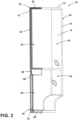
- the trim breaker 18 may further include the central portion 30, as illustrated in FIGS. 2 and 3 .
- the central portion 30 extends between the first and second vertical portions 22, 24 and may be integrally formed with the first and second vertical portions 22, 24 such that the trim breaker 18 is formed as a single piece. As shown in FIG. 2 , the central portion 30 is positioned between the top and bottom portions 26, 28 to divide the cabinet 12 between the refrigeration compartment 50 and the freezer compartment 54.
- the central portion 30 further separates each of the first and second vertical portions 22, 24 into an upper section 66 and a lower section 68.
- the upper sections 66 of each of the first and second vertical portions 22 are positioned on opposing sides of the refrigeration compartment 50, and the lower sections 68 of each of the first and second vertical portions 22, 24 are positioned on opposing sides of the freezer compartment 54.
- an upper inner edge 70 extends along the upper sections 66 of each of the first and second vertical portions 22, 24, the top portion 26, and the central portion 30.
- the upper inner edge 70 is positioned within and spaced apart from the outer rim 38 by the top portion 26 and the upper sections 66 of the first and second vertical portions 22, 24 and extends along an upper edge of the central portion 30.
- the upper inner edge 70 may extend forward of the trim breaker 18 in the same direction as the outer rim 38 and may be configured to form an inner rim.
- the upper inner edge 70 may be substantially aligned with the portions 22, 24, 26, 28, 30 of the trim breaker 18.
- a lower inner edge 72 extends along the bottom portion 28, the central portion 30, and the lower sections 68 of each of the first and second vertical portions 22, 24.
- the lower inner edge 72 is positioned within and spaced apart from the outer rim 38 along the bottom portion 28 and the lower sections 68 of the first and second vertical portions 22, 24 and extends along a lower edge of the central portion 30.
- the lower inner edge 72 may extend forward of the trim breaker 18 in the same direction as the outer rim 38 and may be configured to form an inner rim.
- the lower inner edge 72 may be substantially aligned with the portions 22, 24, 26, 28, 30 of the trim breaker 18.
- the upper inner edge 70 defines an upper opening 74
- the lower inner edge 72 defines a lower opening 76.
- the upper opening 74 is configured to be in communication with the refrigeration compartment 50
- the lower opening 76 is configured to be in communication with the freezer compartment 54 (see FIG. 2 ).
- the central portion 30 includes an outer surface 86 extending between the upper inner edge 70 and the lower inner edge 72.
- the outer surface 86 extends horizontally between the first and second vertical portions 22, 24 of the trim breaker 18 and is integrally formed therewith.
- each of the first and second vertical portions 22, 24 may include a space 90 proximate the central portion 30.
- the space 90 may be defined by the outer rim 38 and may be sized to correspond to the distance between the upper and lower inner edges 70, 72 spaced apart by the central portion 30.
- the outer rim 38 extends inward toward the central portion 30 to define the space 90 such that the space 90 is aligned with a corresponding end of the central portion 30.
- the trim breaker 18 may include a first plurality of ribs 36. As illustrated in FIG. 3 , the first plurality of ribs 36 is positioned on one of the first and second vertical portions 22, 24 of the trim breaker 18. While only the first vertical portion 22 is described in detail as having a first plurality of ribs 36, it will be understood that the second vertical portion 24 may also include a corresponding first plurality of ribs 36. The positioning of the ribs on each of the vertical portions 22, 24 may be configured to be symmetric or may vary without departing from the scope of the present disclosure.
- Each of the first plurality of ribs 36 extends from the outer rim 38 proximate the space 90 and along the outer surface 86 of the central portion 30.
- the first plurality of ribs 36 includes one central rib 94 extending horizontally along the central portion 30.
- the at least one central rib 94 may be one of multiple central ribs 94 spaced apart along the outer edge 38 of the trim breaker 18.
- Each of the central ribs 94 may extend substantially perpendicularly from the outer edge 38 of the trim breaker 18, as best shown in Fig. 4 .
- the central ribs 94 may be spaced equidistantly along the outer rim 38 or the central ribs 94 may be unevenly spaced along the outer rim 38.
- the first plurality of ribs 36 may include angled ribs 96, 98 positioned on opposing sides of the central rib(s) 94.
- the first plurality of ribs 36 may have one or more interior angled ribs 96 extending from the outer rim 38 of the trim breaker 18 along the central portion 30 and toward one of the upper and lower inner edges 70, 72.
- the interior angled ribs 96 may be positioned in pairs such that the central ribs 94 are framed by the interior angled ribs 96.
- the first plurality of ribs 36 may further have one or more exterior angled ribs 98 positioned to extend from the outer rim 38 of the trim breaker 18 toward one of the upper and lower inner edges 70, 72.
- the first plurality of ribs 36 is arranged such that the interior angled ribs 96 are positioned between the exterior angled ribs 98 and the central ribs 94. It will be understood that the first plurality of ribs 36 may include any number of central ribs 94 and any number of angled ribs 98 without departing from the scope of the present disclosure.
- the trim breaker 18 may include a second plurality of ribs 40 at one of the lower corners 34. It will be understood that the trim breaker 18 may include the same or similar arrangement of a plurality of ribs 40 on each of the lower corners 34 and may include the same or a similar arrangement of a plurality of ribs 40 on one or more of the upper corners 32 without departing from the scope of the present disclosure.
- Each of the first and second vertical portions 22, 24 may include a first surface 110 and a second surface 112.
- the first surface 110 is positioned proximate the lower inner edge 72
- the second surface 112 is positioned proximate the outer rim 38 of the trim breaker 18.
- the first surface 110 may extend outward from the second surface 112 to form a plateau or step extending parallel to the outer rim 38 and/or the lower inner edge 72.
- the second plurality of ribs 40 includes a central corner rib 120 positioned diagonally across the respective lower corner 34.
- the central corner rib 120 extends from the outer rim 38 to the lower inner edge 72 and may be integrally formed with one or both of the outer rim 38 and the lower inner edge 72.
- the second plurality of ribs 40 may further includes a first pair of outer ribs 122 positioned on opposing sides of the central corner rib 120. Each of the first pair of outer ribs 122 extends substantially perpendicularly from the outer rim 38 and across one of the bottom portion 28 and the vertical portion 22.
- one of the first pair of perpendicular ribs 122 extends vertically across the bottom portion 28 between the outer rim 38 and the lower inner edge 72, and the other of the first pair of outer ribs 122 extends horizontally across the lower section 68 of the vertical portion 22 between the outer rim 38 and the lower inner edge 72.
- each of the first pair of outer ribs 122 may be further integrally formed with the central corner rib 120 proximate the lower inner edge 72 to form rounded joints 136.
- the second plurality of ribs 40 may further include a second pair of outer ribs 126 extending from the outer rim 38.
- Each of the second pair of outer ribs 126 may be positioned substantially parallel to and spaced apart from a corresponding rib of the first pair of outer ribs 122.
- one of the second pair of outer ribs 126 extends vertically across at least part of the bottom portion 28.
- the other of the second pair of outer ribs 126 extends horizontally across at least part of the lower section 68 of the vertical portion 22.
- the second pair of outer ribs 126 may be sized to extend from the outer rim 38 toward the lower inner edge 72 and may be spaced apart from the lower inner edge 72.
- second pair of outer ribs 126 may extend to and be integrally formed with the lower inner edge 72 without departing from the scope of the present disclosure. It will further be understood that any number of spaced apart outer ribs 122, 126 may be used without departing from the scope of the present disclosure.
- each of the second plurality of ribs 40 includes a lip 130 configured to align with the step 114 between the first and second surfaces 110, 112 of the trim breaker 18.
- the lip 130 may be defined such that each of the second plurality of ribs 40 is formed with and/or contacts the respective portion 22, 24, 26, 28 of the trim breaker 18 continuously along the length of the rib 120, 122, 126.
- Each of the second plurality of ribs 40 may include an inclined surface 132 aligned with the lip 130 configured to accommodate the offset between the first and second surfaces 110, 112 of the trim breaker 18.
- the second plurality of ribs 40a includes a central corner rib 120a, a first pair of outer ribs 122a, and a second pair of outer ribs 126a.
- Each of the second plurality of ribs 40 extends from the outer rim 38 toward the lower inner edge 72 and is spaced apart from the lower inner edge 72. It is contemplated that each of the second plurality of ribs 40a may extend the same distance from the outer rim 38 or extend varying distances without departing from the scope of the present disclosure. It is further contemplated that one or more of the second plurality of ribs 40a may be joined and integrally formed at any end or may be independent from the other ribs of the second plurality of ribs 40a.
- the first and second pluralities of ribs 36, 40 are configured to reduce the strain placed on the trim breaker 18 during vacuum sealing of the insulation cavity 20.
- the first and second pluralities of ribs 36, 40 may be configured to allow the trim breaker 18 to be made from a material having a low thermal conductivity and provide additional stiffness in the trim breaker 18.
- the first and second pluralities of ribs 36, 40 may also help control buckling during assembly and may help to maintain the wall thickness of the inner liner 14 and/or the outer wrapper 16 for thermal requirements by reducing the stress level in the trim breaker 18. This may also increase effectiveness of the coupling of the trim breaker 18 with the cabinet 12 (e.g., may reduce stress and strain on adhesive used therein).
- a refrigerator appliance includes a cabinet having an inner liner spaced apart from an outer wrapper and a trim breaker extending between the inner liner and the outer wrapper to define an insulating cavity therebetween.
- the trim breaker includes first and second opposing vertical portions, a top portion, a bottom portion, and a central portion.
- the top portion is integrally formed with each vertical portion at a respective upper corner
- the bottom portion is integrally formed with each vertical portion at a respective lower corner.
- a first plurality of ribs extends from an outer rim of the trim breaker and at least partially along the central portion, and a second plurality of ribs extends from the outer rim of at least one of the first and second vertical portions and across at least one of the upper and lower corners.
- a first plurality of ribs extends from each of first and second vertical portions and along a central portion of a trim breaker.
- each of a first plurality of ribs is integrally formed with an outer rim of a trim breaker.
- a first plurality of ribs includes at least one central rib and at least one angled rib.
- the central rib extends substantially parallel along a central portion of a trim breaker, and the at least one angled rib extends from an outer rim of the trim breaker toward one of an upper or lower edge of the central portion.
- each of a second plurality of ribs is integrally formed with an outer rim of the trim breaker.
- a second plurality of ribs includes a central corner rib extending diagonally from an outer rim of a trim breaker to an inner edge of the trim breaker and a first pair of outer ribs extending substantially perpendicularly from the outer rim toward the inner edge.
- outer corner ribs are integrally formed with at least one of an inner edge of a trim breaker and a central corner rib.
- a second plurality of ribs includes a second pair of outer corner ribs extending substantially perpendicularly from an outer rim of a trim breaker toward an inner edge of the trim breaker and spaced apart from the inner edge of the trim breaker.
- each rib of a second pair of outer ribs is spaced apart from a corresponding rib of a first pair of outer ribs.
- a trim breaker for an appliance includes first and second opposing vertical portions and a central portion integrally formed with the first and second opposing vertical portions.
- a plurality of ribs extends from an outer rim of at least one of the first and second vertical portions and at least partially along the central portion.
- the plurality of ribs includes at least one central rib and at least one angled rib.
- At least one central rib of a plurality of ribs is substantially horizontal and extends between upper and lower inner edges of a trim breaker.
- At least one angled rib of a plurality of ribs includes an interior angled rib and an exterior angled rib.
- Each of the interior and exterior angled ribs extends toward one of upper and lower inner edges of a trim breaker.
- an interior angled rib is positioned between a central rib and an exterior angled rib.
- an outer rim of a trim breaker defines a space proximate a central portion, and a plurality of ribs is integrally formed with the outer rim proximate the space.
- a trim breaker for an appliance includes first and second opposing vertical portions, a top portion, and a bottom portion.
- the top portion is integrally formed with each vertical portion at a respective upper corner
- the bottom portion is integrally formed with each vertical portion at a respective lower corner.
- An outer rim extends about a periphery of the first and second opposing vertical portions, the top portion, and the bottom portion.
- An inner edge of the trim breaker defines an opening and is interior of the outer rim.
- a plurality of ribs extends from the outer rim of at least one of the first and second vertical portions and across at least one of the upper and lower corners. The plurality of ribs includes at least one central corner rib extending from the outer rim toward the inner edge.
- a central corner rib is integrally formed with an outer rib.
- the outer rib extends substantially perpendicular to an outer rim of a portion of a trim breaker.
- an outer rib is integrally formed with one of a central corner rib and an inner edge of a trim breaker.
- a central corner rib is integrally formed with an outer rim of a trim breaker and an inner edge of the trim breaker.
- each of a second plurality of ribs is spaced apart from an inner edge of a trim breaker.
- a trim breaker includes a first surface offset from a second surface by a step.
- Each of a second plurality of ribs includes a lip configured to be aligned with the step.
- a refrigerator appliance comprises:
- the first plurality of ribs (36) extends from each of the first and second vertical portions (22, 24) and along the central portion (30).
- each of the first plurality of ribs (36) is integrally formed with the outer rim (38) of the trim breaker (18).
- the first plurality of ribs (36) includes at least one central rib (94) and at least one angled rib (96, 98).
- At least one central rib (94) extends substantially parallel along the central portion (30) and the at least one angled rib (96, 98) extends from the outer rim (38) toward one of an upper inner edge (70) or a lower inner edge (72) of the central portion (30).
- each of the second plurality of ribs (40) is integrally formed with the outer rim (38) of the trim breaker (18).
- the second plurality of ribs (40) includes a central corner rib (120) and a first pair of outer ribs (122), the central corner rib (120) extending in particular diagonally from the outer rim (38) toward the lower inner edge (72) or to the lower inner edge (72), the first pair of outer ribs (122) extending in particular substantially perpendicularly from the outer rim (38) toward the lower inner edge (72) or to the lower inner edge (72).
- the first pair of outer corner ribs (122) are integrally formed with at least one of the lower inner edge (72) and the central corner rib (120).
- the second plurality of ribs (40) includes a second pair of outer ribs (126) extending substantially perpendicularly from the outer rim (38) toward the lower inner edge (72) and spaced apart from the lower inner edge (72) of the trim breaker (18).
- each rib of the second pair of outer ribs (126) is spaced apart from the corresponding rib of the first pair of outer ribs (122).
- the at least one central rib (94) is substantially horizontal and extends between the upper and lower inner edges (70, 72) of the trim breaker (18).
- the at least one angled rib (96, 98) includes an interior angled rib (96) and an exterior angled rib (98), each of the interior and exterior angled ribs (96, 98) extending toward one of the upper and lower inner edges (70, 72) of the trim breaker (18).
- the interior angled rib (96) is positioned between the central rib (94) and the exterior angled rib (98).
- the outer rim (38) defines a space (90) proximate the central portion (30), and further wherein at least one of the first and second plurality of ribs (36, 40) is integrally formed with the outer rim (38) proximate the space (90).
- the term "coupled” in all of its forms, couple, coupling, coupled, etc. generally means the joining of two components (electrical or mechanical) directly or indirectly to one another. Such joining may be stationary in nature or movable in nature. Such joining may be achieved with the two components (electrical or mechanical) and any additional intermediate members being integrally formed as a single unitary body with one another or with the two components. Such joining may be permanent in nature or may be removable or releasable in nature unless otherwise stated.
- elements shown as integrally formed may be constructed of multiple parts or elements shown as multiple parts may be integrally formed, the operation of the interfaces may be reversed or otherwise varied, the length or width of the structures and/or members or connector or other elements of the system may be varied, the nature or number of adjustment positions provided between the elements may be varied.
- the elements and/or assemblies of the system may be constructed from any of a wide variety of materials that provide sufficient strength or durability, in any of a wide variety of colors, textures, and combinations. Accordingly, all such modifications are intended to be included within the scope of the present innovations. Other substitutions, modifications, changes, and omissions may be made in the design, operating conditions, and arrangement of the desired and other exemplary embodiments without departing from the spirit of the present innovations.
Landscapes
- Engineering & Computer Science (AREA)
- Chemical & Material Sciences (AREA)
- Combustion & Propulsion (AREA)
- Physics & Mathematics (AREA)
- Mechanical Engineering (AREA)
- Thermal Sciences (AREA)
- General Engineering & Computer Science (AREA)
- Refrigerator Housings (AREA)
- Switch Cases, Indication, And Locking (AREA)
- Vehicle Interior And Exterior Ornaments, Soundproofing, And Insulation (AREA)
- Steering Controls (AREA)
Applications Claiming Priority (2)
| Application Number | Priority Date | Filing Date | Title |
|---|---|---|---|
| US17/153,448 US11709013B2 (en) | 2021-01-20 | 2021-01-20 | Appliance trim breaker |
| EP22152119.8A EP4033184B1 (de) | 2021-01-20 | 2022-01-18 | Geräteverkleidungsübergangsstück |
Related Parent Applications (2)
| Application Number | Title | Priority Date | Filing Date |
|---|---|---|---|
| EP22152119.8A Division-Into EP4033184B1 (de) | 2021-01-20 | 2022-01-18 | Geräteverkleidungsübergangsstück |
| EP22152119.8A Division EP4033184B1 (de) | 2021-01-20 | 2022-01-18 | Geräteverkleidungsübergangsstück |
Publications (2)
| Publication Number | Publication Date |
|---|---|
| EP4459210A2 true EP4459210A2 (de) | 2024-11-06 |
| EP4459210A3 EP4459210A3 (de) | 2025-01-08 |
Family
ID=79730166
Family Applications (2)
| Application Number | Title | Priority Date | Filing Date |
|---|---|---|---|
| EP24201109.6A Pending EP4459210A3 (de) | 2021-01-20 | 2022-01-18 | Kühlschrank mit einem trimmschalter mit verstärkungsrippen |
| EP22152119.8A Active EP4033184B1 (de) | 2021-01-20 | 2022-01-18 | Geräteverkleidungsübergangsstück |
Family Applications After (1)
| Application Number | Title | Priority Date | Filing Date |
|---|---|---|---|
| EP22152119.8A Active EP4033184B1 (de) | 2021-01-20 | 2022-01-18 | Geräteverkleidungsübergangsstück |
Country Status (3)
| Country | Link |
|---|---|
| US (2) | US11709013B2 (de) |
| EP (2) | EP4459210A3 (de) |
| CN (1) | CN114812045A (de) |
Families Citing this family (2)
| Publication number | Priority date | Publication date | Assignee | Title |
|---|---|---|---|---|
| CN113915924A (zh) * | 2020-07-09 | 2022-01-11 | 青岛海尔电冰箱有限公司 | 箱体及冰箱 |
| KR20240073659A (ko) * | 2022-11-18 | 2024-05-27 | 삼성전자주식회사 | 냉장고 |
Citations (2)
| Publication number | Priority date | Publication date | Assignee | Title |
|---|---|---|---|---|
| US2644603A (en) | 1950-01-14 | 1953-07-07 | Int Harvester Co | Breaker strip construction |
| US5720536A (en) | 1995-03-27 | 1998-02-24 | General Electric Company | Refrigerator with improved breaker strip assembly |
Family Cites Families (16)
| Publication number | Priority date | Publication date | Assignee | Title |
|---|---|---|---|---|
| US2587922A (en) * | 1949-04-07 | 1952-03-04 | Int Harvester Co | Breaker strip construction |
| DE19907182A1 (de) | 1999-02-19 | 2000-08-24 | Bsh Bosch Siemens Hausgeraete | Wärmeisolierende Wand |
| US8943770B2 (en) | 2009-11-20 | 2015-02-03 | Electrolux Home Products Pty Limited | Insulated panel and method of assembly |
| KR101147779B1 (ko) | 2010-10-28 | 2012-05-25 | 엘지전자 주식회사 | 진공공간부를 구비하는 냉장고 |
| KR102254221B1 (ko) | 2014-10-07 | 2021-05-20 | 삼성전자주식회사 | 냉장고 |
| US20160258671A1 (en) * | 2015-03-02 | 2016-09-08 | Whirlpool Corporation | Gas barrier for vacuum insulation |
| KR20160115445A (ko) | 2015-03-27 | 2016-10-06 | 삼성전자주식회사 | 냉장고 |
| US10807298B2 (en) * | 2015-12-29 | 2020-10-20 | Whirlpool Corporation | Molded gas barrier parts for vacuum insulated structure |
| WO2018022009A1 (en) * | 2016-07-26 | 2018-02-01 | Whirlpool Corporation | Thermal bridgebreaker and seal features in a thin-walled vacuum insulated structure |
| WO2018022006A1 (en) * | 2016-07-26 | 2018-02-01 | Whirlpool Corporation | A method for manufacturing an insulated structure for a refrigerator |
| CN112188852B (zh) * | 2018-05-23 | 2023-01-03 | 惠而浦公司 | 电器铰链组件 |
| US11460143B2 (en) * | 2019-05-21 | 2022-10-04 | Whirlpool Corporation | Collapsible pattern |
| US10914514B1 (en) * | 2020-01-17 | 2021-02-09 | Whirlpool Corporation | Illuminated trim assembly for appliance |
| US11486629B2 (en) * | 2020-06-25 | 2022-11-01 | Whirlpool Corporation | Refrigeration appliance cabinet assembly |
| US11448355B2 (en) * | 2021-01-12 | 2022-09-20 | Whirlpool Corporation | Vacuum insulated refrigerator structure with feature for controlling deformation and improved air withdrawal |
| US11340008B1 (en) * | 2021-01-20 | 2022-05-24 | Whirlpool Corporation | Appliance trim breaker assembly |
-
2021
- 2021-01-20 US US17/153,448 patent/US11709013B2/en active Active
- 2021-12-30 CN CN202111660945.2A patent/CN114812045A/zh active Pending
-
2022
- 2022-01-18 EP EP24201109.6A patent/EP4459210A3/de active Pending
- 2022-01-18 EP EP22152119.8A patent/EP4033184B1/de active Active
-
2023
- 2023-06-08 US US18/331,440 patent/US12313332B2/en active Active
Patent Citations (2)
| Publication number | Priority date | Publication date | Assignee | Title |
|---|---|---|---|---|
| US2644603A (en) | 1950-01-14 | 1953-07-07 | Int Harvester Co | Breaker strip construction |
| US5720536A (en) | 1995-03-27 | 1998-02-24 | General Electric Company | Refrigerator with improved breaker strip assembly |
Also Published As
| Publication number | Publication date |
|---|---|
| US20220228795A1 (en) | 2022-07-21 |
| EP4033184B1 (de) | 2024-11-06 |
| EP4459210A3 (de) | 2025-01-08 |
| EP4033184A1 (de) | 2022-07-27 |
| US12313332B2 (en) | 2025-05-27 |
| US11709013B2 (en) | 2023-07-25 |
| CN114812045A (zh) | 2022-07-29 |
| US20230314065A1 (en) | 2023-10-05 |
Similar Documents
| Publication | Publication Date | Title |
|---|---|---|
| US11692765B2 (en) | Appliance trim breaker assembly | |
| EP4033184B1 (de) | Geräteverkleidungsübergangsstück | |
| US10907883B2 (en) | Hinge support assembly | |
| US20200278149A1 (en) | Vacuum insulated structure with internal airway system | |
| US11898791B2 (en) | Appliance door gasket assembly | |
| US11150008B2 (en) | Cabinet reinforcing assembly | |
| US11898790B2 (en) | Trim breaker for an insulated appliance | |
| US10386111B2 (en) | Home appliance device and method for assembling a home appliance device | |
| EP4227617A1 (de) | Kühleinheit | |
| EP3929514A1 (de) | Kühlgeräteschrankanordnung | |
| JP6719646B2 (ja) | 冷蔵庫 | |
| JP7106205B2 (ja) | 冷却貯蔵庫 | |
| CN107735633A (zh) | 冷藏库 | |
| CN117120793B (zh) | 搁板构件及冰箱 | |
| EP4600590A1 (de) | Kühlschrank | |
| JP7610836B2 (ja) | 棚部材 | |
| JP2024015242A (ja) | 冷蔵庫およびその製造方法 | |
| JP4967558B2 (ja) | 冷蔵庫 | |
| CN119755873A (zh) | 冰箱 |
Legal Events
| Date | Code | Title | Description |
|---|---|---|---|
| PUAI | Public reference made under article 153(3) epc to a published international application that has entered the european phase |
Free format text: ORIGINAL CODE: 0009012 |
|
| STAA | Information on the status of an ep patent application or granted ep patent |
Free format text: STATUS: THE APPLICATION HAS BEEN PUBLISHED |
|
| AC | Divisional application: reference to earlier application |
Ref document number: 4033184 Country of ref document: EP Kind code of ref document: P |
|
| AK | Designated contracting states |
Kind code of ref document: A2 Designated state(s): AL AT BE BG CH CY CZ DE DK EE ES FI FR GB GR HR HU IE IS IT LI LT LU LV MC MK MT NL NO PL PT RO RS SE SI SK SM TR |
|
| PUAL | Search report despatched |
Free format text: ORIGINAL CODE: 0009013 |
|
| AK | Designated contracting states |
Kind code of ref document: A3 Designated state(s): AL AT BE BG CH CY CZ DE DK EE ES FI FR GB GR HR HU IE IS IT LI LT LU LV MC MK MT NL NO PL PT RO RS SE SI SK SM TR |
|
| RIC1 | Information provided on ipc code assigned before grant |
Ipc: F25D 23/08 20060101AFI20241202BHEP |
|
| STAA | Information on the status of an ep patent application or granted ep patent |
Free format text: STATUS: REQUEST FOR EXAMINATION WAS MADE |
|
| 17P | Request for examination filed |
Effective date: 20250627 |
|
| GRAP | Despatch of communication of intention to grant a patent |
Free format text: ORIGINAL CODE: EPIDOSNIGR1 |
|
| STAA | Information on the status of an ep patent application or granted ep patent |
Free format text: STATUS: GRANT OF PATENT IS INTENDED |
|
| INTG | Intention to grant announced |
Effective date: 20260304 |