EP4458530A1 - Robotersystem - Google Patents
Robotersystem Download PDFInfo
- Publication number
- EP4458530A1 EP4458530A1 EP22915604.7A EP22915604A EP4458530A1 EP 4458530 A1 EP4458530 A1 EP 4458530A1 EP 22915604 A EP22915604 A EP 22915604A EP 4458530 A1 EP4458530 A1 EP 4458530A1
- Authority
- EP
- European Patent Office
- Prior art keywords
- workpiece
- hand
- detection surface
- controller
- contact
- Prior art date
- Legal status (The legal status is an assumption and is not a legal conclusion. Google has not performed a legal analysis and makes no representation as to the accuracy of the status listed.)
- Pending
Links
Images


Classifications
-
- B—PERFORMING OPERATIONS; TRANSPORTING
- B25—HAND TOOLS; PORTABLE POWER-DRIVEN TOOLS; MANIPULATORS
- B25J—MANIPULATORS; CHAMBERS PROVIDED WITH MANIPULATION DEVICES
- B25J9/00—Program-controlled manipulators
- B25J9/16—Program controls
- B25J9/1612—Program controls characterised by the hand, wrist, grip control
-
- B—PERFORMING OPERATIONS; TRANSPORTING
- B25—HAND TOOLS; PORTABLE POWER-DRIVEN TOOLS; MANIPULATORS
- B25J—MANIPULATORS; CHAMBERS PROVIDED WITH MANIPULATION DEVICES
- B25J13/00—Controls for manipulators
- B25J13/08—Controls for manipulators by means of sensing devices, e.g. viewing or touching devices
- B25J13/081—Touching devices, e.g. pressure-sensitive
- B25J13/084—Tactile sensors
-
- B—PERFORMING OPERATIONS; TRANSPORTING
- B25—HAND TOOLS; PORTABLE POWER-DRIVEN TOOLS; MANIPULATORS
- B25J—MANIPULATORS; CHAMBERS PROVIDED WITH MANIPULATION DEVICES
- B25J15/00—Gripping heads and other end effectors
- B25J15/06—Gripping heads and other end effectors with vacuum or magnetic holding means
- B25J15/0616—Gripping heads and other end effectors with vacuum or magnetic holding means with vacuum
-
- G—PHYSICS
- G05—CONTROLLING; REGULATING
- G05B—CONTROL OR REGULATING SYSTEMS IN GENERAL; FUNCTIONAL ELEMENTS OF SUCH SYSTEMS; MONITORING OR TESTING ARRANGEMENTS FOR SUCH SYSTEMS OR ELEMENTS
- G05B2219/00—Program-control systems
- G05B2219/30—Nc systems
- G05B2219/39—Robotics, robotics to robotics hand
- G05B2219/39567—Use electromagnetic attraction to bring robot hand in contact with workpiece
-
- G—PHYSICS
- G05—CONTROLLING; REGULATING
- G05B—CONTROL OR REGULATING SYSTEMS IN GENERAL; FUNCTIONAL ELEMENTS OF SUCH SYSTEMS; MONITORING OR TESTING ARRANGEMENTS FOR SUCH SYSTEMS OR ELEMENTS
- G05B2219/00—Program-control systems
- G05B2219/30—Nc systems
- G05B2219/40—Robotics, robotics mapping to robotics vision
- G05B2219/40625—Tactile sensor
Definitions
- the present application mainly relates to a robot system that attracts and holds a workpiece using an attraction pad.
- PTL 1 discloses a picking apparatus using an attraction hand to attract a workpiece.
- the attraction hand uses magnetic force generated by a magnet to attract the workpiece.
- a shaft is fixed to the magnet.
- the magnet and the shaft are covered by a cover.
- the cover can slide vertically with respect to the magnet and the shaft.
- the cover is located at a lower side under its own weight. As the attraction hand approaches the workpiece, the bottom surface of the cover is pushed upward by the workpiece and the cover slides upward with respect to the magnet and the shaft.
- the optical sensor is attached to the attraction hand.
- the optical sensor includes a light emitter and a light receiver.
- the optical sensor detects whether the light receiver received the light emitted from the light emitter.
- the light emitter is fixed to the cover.
- the light receiver is fixed to the shaft.
- the picking apparatus of the PTL 1 can detect that the attraction hand is located close to the workpiece based on the detected value obtained by the optical sensor.
- the picking apparatus detects the approach of the attraction hand to the workpiece, the picking apparatus slows down a descending speed of the attraction hand. Accordingly, the impact that the picking apparatus gives on the workpiece can be reduced.
- PTL 1 does not discloses changing the orientation of the hand with respect to the workpiece. Therefore, depending on the type of the workpiece and of the attraction hand that are to use, the workpiece may not be properly attracted and held.
- the present application is made in view of the situation described above and its main purpose is to provide a robot system that can attract and hold a workpiece properly by changing an orientation of a hand with respect to the workpiece.
- the robot system includes a robot, an attraction pad, a sensor, and a controller.
- the robot includes a hand whose orientation is changeable.
- the attraction pad is attached to the hand, attracts a workpiece, and holds the workpiece.
- the sensor is attached to the hand, includes the detection surface, and detects contact between the detection surface and the workpiece.
- the controller can determine whether the workpiece has been brought into surface contact with the detection surface based on a result of detection made by the sensor and changes the orientation of the hand, until the workpiece makes surface contact with the detection surface, and then makes the attraction pad hold the workpiece.
- the robot system can attract and hold the workpiece properly by changing the orientation of the hand with respect to the workpiece.
- the robot system 1 is arranged in an institution, such as a factory or a warehouse.
- the robot system 1 includes a robot 10 and a controller 40.
- the robot system 1 is a system for making the robot 10 perform a task.
- the task that the robot 10 performs is a picking-up task to handle a workpiece 52 which is a work object.
- the picking-up task is a task to pick up the workpiece 52 and transfer it to another location.
- the workpiece 52 is placed in a container 51.
- the workpiece 52 may be placed in another containing unit or may be placed on a conveyor.
- the shape of the workpiece 52 of the present embodiment is cuboid.
- the cuboid shape is not limited to an exact cuboid shape, but the term includes a shape that is substantially cuboid.
- the shape of the workpiece 52 is not limited to cuboid shape. Though, it preferably includes more than one plane on its outer surface.
- the robot 10 includes a base 11, arms 12, and a hand 15.
- the robot 10 of the present embodiment is a vertical articulated type.
- the robot 10 is not limited to the vertical articulated type, but it may be various types as long as it can change the orientation of the hand 15.
- the base 11 is fixed to a suitable location in the institution, such as the surface of the floor, a supporting base, or the surface of the ceiling.
- the proximal end of the arms 12 is connected to the base 11.
- the arms 12 are connected to each other.
- the hand 15 is connected to the distal end of the arms 12.
- An encoder 13 and an actuator 14 are attached to each point where these members are connected.
- the encoder 13 detects displacement of one member with respect to the other member.
- a rotary encoder is used.
- a linear encoder is used.
- the detected value obtained by the encoder 13 is output to the controller 40.
- the actuator 14 is, for example, an electronic motor or an electric cylinder and it generates power to move one member with respect to the other member.
- the actuator 14 is controlled by the controller 40.
- the controller 40 is a computer that includes a processing apparatus, such as a CPU, a storage apparatus, such as a HDD, a SSD, and a flash memory, and a wired or wireless communicating apparatus.
- the controller 40 can perform various functions when the processing apparatus executes a program stored in the storage apparatus.
- the controller 40 can also send and receive data using the communicating apparatus.
- the data that the controller 40 receives is, for example, the detected value obtained by the encoder 13 or by another sensor.
- the data that the controller 40 sends is, for example, a signal to operate the actuator 14.
- the controller 40 can change the position and the orientation of the hand 15 by operating the actuator 14 with reference to the detected value obtained by the encoder 13.
- a lifting apparatus 21, an attraction pad 22, and a sensor 32 are attached to the hand 15. As the position and orientation of the hand 15 is changed, the positions and orientations of the lifting apparatus 21, the attraction pad 22, and the sensor 32 are also changed.
- the lifting apparatus 21 is an actuator, such as a cylinder.
- the lifting apparatus 21 can slide with respect to the hand 15 under the power of the actuator.
- the lifting apparatus 21 is controlled by the controller 40.
- the attraction pad 22 is attached to one end of the lifting apparatus 21. Accordingly, the attraction pad 22 can be raised and lowered.
- the attraction pad 22 attracts the workpiece 52.
- the attraction pad 22 of the present embodiment is a vacuum suction type.
- the vacuum suction type is a type in which an article is attracted and held by negative pressure generated within the pad.
- the attraction pad 22 is not limited to the vacuum suction type.
- the workpiece 52 when the workpiece 52 is magnetic, the workpiece 52 may be attracted by a magnet.
- the sensor 32 includes a detection surface 32a.
- the sensor 32 detects contact between the detection surface 32a and the workpiece 52.
- On the detection surface 32a more than one minute tactile sensor is arranged in a planar way.
- the tactile sensors are, for example, capacitive, electrical-resistive, or piezoelectric. Each tactile sensor outputs the magnitudes of the received force as an electrical signal. Based on the detected value obtained by each tactile sensor, the contact between the detection surface 32a and the workpiece 52 can be determined.
- the sensor 32 contacts with the side face of the workpiece. In other words, the attracted face of the workpiece 52 and the detected face of the workpiece 52 are different faces.
- a contact sensor that detects whether an object has been brought into contact may be used.
- the contact sensor is, for example, a limit switch.
- the sensor 32 is flexible. That is, when the sensor 32 makes contact with the workpiece 52 while the hand 15 is moving, the sensor bends along the workpiece 52 while detecting the contact with the workpiece 52. Accordingly, since strong force will not be applied to the sensor 32, the sensor 32 is prevented from being damaged.
- the sensor 32 may not be flexible.
- the workpiece 52 is placed irregularly in the container 51. In such a situation, it is difficult to pick up the workpiece 52 properly using the teaching playback method, in which the robot 10 is taught in advance and operates as taught. Therefore, in the present embodiment, the workpiece 52 is searched for while moving the hand 15 and the workpiece 52 is picked up when the workpiece 52 is detected.
- FIG. 3 shows a flowchart for performing the workpiece search.
- the flowchart shown in FIG. 3 is executed by the controller 40.
- the controller changes the position and orientation of the hand 15 by controlling the actuator 14 with reference to the value obtained by the encoder 13 is expressed as, simply, that the controller 40 changes the position and orientation of the hand 15.
- the controller 40 sets the hand 15 at an initial height (S101).
- the initial height is a height at which the hand 15 is placed when starting the workpiece search.
- the initial height is the highest of the heights at which the search is performed.
- the controller 40 searches the inside of the container 51 entirely at the initial height.
- two directions that cross each other at right angles in a horizontal plane are referred to as a first horizontal direction and a second horizontal direction.
- the first horizontal direction and the second horizontal direction can also be expressed as crossing each other at right angles in a plane parallel to the bottom face of the container 51. If the container 51 is cuboid, the first horizontal direction and the second horizontal direction may be defined to be parallel to the sides of the container 51.
- the directions for defining the first horizontal direction and the second horizontal direction are not limited to this.
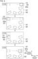
- the controller 40 moves the hand 15 in the first horizontal direction to search for the workpiece 52 (S102). At this time, as shown in FIG. 4 , the hand 15 is moved with such an orientation that the attraction pad 22 is positioned ahead of the detection surface 32a. To be positioned ahead means to be positioned downstream in the direction of movement. Accordingly, at the time when the sensor 32 detects the workpiece 52, the attraction pad 22 can be positioned above the workpiece 52.
- the positional relation between the attraction pad 22 and the sensor 32 during the workpiece search may differ from that of the present embodiment.
- the workpiece 52 may be searched for with the sensor 32 positioned ahead.
- the orientation of the hand 15 is adjusted according to the workpiece 52 and, after that, the hand 15 is translated so that the attraction pad 22 is positioned above the workpiece 52.
- the controller 40 moves the hand 15 back to the position at which the search in step S102 was started (S103).
- the workpiece 52 in this path has already been searched for. Therefore, the controller 40 moves the hand 15 back to the original position without changing the orientation of the hand 15.
- the controller 40 moves the hand 15 in the second horizontal direction to search for the workpiece 52 (S104). Before starting to move the hand 15 in the second horizontal direction, the controller 40 rotates the hand 15 to position the attraction pad 22 ahead of the detection surface 32a.
- the controller 40 determines whether the search at the present height is finished (S105). As this moment, the entire container 51 in plan view has not been completely searched. Therefore, the controller 40 performs the processes of step S102 to S104 again. In this manner, by repeating the processes of step S102 to S104, the search at the same height is continued.
- the controller 40 determines whether the container 51 has been searched to the bottom (S106).
- the distance from the initial height to the bottom of the container 51 is registered in advance in the controller 40 or the like.
- the controller 40 moves the hand 15 to the position at which the search was started and lowers it (S107, FIG. 5 ). The controller 40 then repeats the processes of step S102 to S106 again. Then, when it determines that the container 51 has been searched to the bottom, it terminates the process.
- the workpiece 52 is irregularly arranged in the container 51. Therefore, the orientation of the hand 15 with respect to the workpiece 52 at a time when the workpiece 52 is detected may not be always appropriate.
- the controller 40 changes the orientation of the hand 15 to adjust it appropriately with respect to the workpiece 52. That the orientation of the hand 15 with respect to the workpiece 52 is appropriate means that the attraction pad 22 and the workpiece 52 overlaps with each other in plan view and the attraction pad 22 can make surface contact with a plane face of the workpiece 52.
- the detection surface 32a is divided into a left portion and a right portion.
- the right side and the left side when heading in the travel direction are the right portion and the left portion, respectively.
- the controller 40 can determine whether the workpiece 52 has been brought into contact with the left portion or the right portion of the detection surface 32a. At this point, basically, the workpiece 52 and the detection surface 32a make line contact with each other.
- the controller 40 rotates the hand 15 with a height direction as a height direction as a center of rotation. Specifically, a position at which the workpiece 52 and the detection surface 32a contact with each other is set as the center of rotation.
- the hand 15 is rotated in such a direction that the right portion of the detection surface 32a approaches the workpiece 52. Accordingly, with the progress of the rotation of the hand 15, the right portion of the detection surface 32a approaches the workpiece 52 and then the right portion of the detection surface 32a makes contact with the workpiece 52. As a result, the detection surface 32a can be brought into surface contact with the workpiece 52.
- the controller 40 rotates the hand 15 in such a direction that the left portion of the detection surface 32a approaches the workpiece 52. Accordingly, the detection surface 32a can be brought into surface contact with the workpiece 52.
- the controller 40 brings the detection surface 32a into surface contact with the workpiece 52. Then, while maintaining the surface contact, the controller 40 controls the lifting apparatus 21 to lower it and attracts and holds the workpiece 52 by the attraction pad 22.
- the position of the center of rotation is not limited to the position at which they contact with each other.
- the hand 15 may be rotated after being moved backward.
- the direction of rotation is not limited to the above-mentioned directions.
- the hand 15 may be rotated in such a direction that the left end of the detection surface 32a approaches the workpiece 52. In this case, since the positions of the attraction pad 22 and the workpiece 52 can be misaligned, the hand 15 may be translated along the workpiece 52 after the detection surface 32a is brought into surface contact with the workpiece 52.
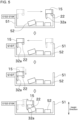
- the detection surface 32a is divided into an upper portion, a central portion, and a lower portion.
- the upper portion is an upper side in the height direction with respect to the central portion and the lower portion is a lower side in the height direction with respect to the central portion.
- the controller 40 can determine whether the workpiece 52 has been brought into contact with the upper portion of the detection 32a, whether with the central portion, and whether with the lower portion.
- the controller 40 controls the lifting apparatus 21 to lower it and attracts and holds the workpiece 52 by the attraction pad 22.
- the controller 40 rotates the hand 15 with a horizontal direction as the center of rotation. Specifically, a position where the workpiece 52 and the detection surface 32a contact with each other is set as the center of rotation. In the present embodiment, the hand 15 is rotated in such a direction that the lower portion of the detection surface 32a approaches the workpiece 52. Accordingly, with the progress of the rotation of the hand 15, the lower portion of the detection surface 32a approaches the workpiece 52 and then the lower portion of the detection surface 32a makes contact with the workpiece 52. In this manner, the detection surface 32a can be brought into surface contact with the workpiece 52. Then, while maintaining the surface contact, the controller 40 controls the lifting apparatus 21 to lower it and attracts and holds the workpiece 52 by the attraction pad 22.
- the controller 40 rotates the hand 15 in such a direction that the upper portion of the detection surface 32a approaches the workpiece 32a. Accordingly, the detection surface 32a can be brought into surface contact with the workpiece 52. Then, while maintaining the surface contact, the controller 40 controls the lifting apparatus 21 to lower it and attracts and holds the workpiece 52 by the attraction pad 22.
- the controller 40 raises the hand 15. The controller 40 then performs the same process as when the workpiece 52 contacts with the lower portion of the detection surface 32a. If there is no possibility of interference between the hand 15 and the workpiece 52, the hand 15 may also be lowered. The controller 40 then performs the same process as when the workpiece 52 contacts with the upper portion of the detection surface 32a.
- the position of the center of rotation is not limited to the position at which they contact with each other.
- the direction of rotation is also not limited to the above-mentioned directions.
- the workpiece 52 may be classified into the upper portion and the lower portion while omitting the center portion.
- the controller 40 may retract the hand 15 before rotating the hand 15 when it determines that the hand 15 and another member, especially the container 51 or the workpiece 52, will interfere each other.
- the position of the container 51 may be registered in advance in the controller 40.
- a detection apparatus that examines the surrounding of the hand 15 may be arranged.
- the detection apparatus is, for example, a radar or a sonar.
- the orientation of the hand 15 with respect to the workpiece 52 in plan view and in side view may not be appropriate.
- the workpiece 52 and the detection surface 32a make point contact with each other.
- the orientation of the hand 15 with respect to the workpiece 52 in plan view may be changed with the method shown in FIG. 7 first and then the orientation of the hand 15 with respect to the workpiece 52 in side view may be changed with the method shown in FIG. 8 .
- the order of the two processes may be swapped.
- the robot system 1 of the present embodiment includes the robot 10, the attraction pad 22, the sensor 32, and the controller 40.
- the robot 10 includes the hand 15 whose orientation is changeable.
- the attraction pad 22 is attached to the hand 15, attracts the workpiece 52, and holds the workpiece 52.
- the sensor 32 is attached to the hand 15, includes the detection surface 32a, and detects contact between the detection surface 32a and the workpiece 52.
- the controller 40 can determine whether the workpiece 52 has been brought into surface contact with the detection surface 32a based on the results of detection made by the sensor 32 and changes the orientation of the hand 15, until the workpiece 52 makes surface contact with the detection surface 32a, and then makes the attraction pad 22 hold the workpiece 52.
- the hand 15 By bringing the workpiece 52 into surface contact with the detection surface 32a, the hand 15 can be adjusted to a predetermined orientation with respect to the workpiece 52. Therefore, the workpiece 52 can be properly attracted and held by using the attraction pad 22.
- the controller 40 when the controller 40 determines that the workpiece 52 is not in surface contact with the detection surface 32a, the controller 40 changes the orientation of the hand 15 until the workpiece 52 makes surface contact with the detection surface 32a.
- the detection surface 32a can be surely brought into surface contact with the workpiece 52.
- the controller 40 changes the orientation of the hand 15 by rotating the hand 15 with a horizontal direction as the center of rotation.
- the orientation of the hand 15 in plan view can be adjusted according to the workpiece 52.
- the detection surface 32a includes the upper portion and the lower portion which is located lower than the upper portion.
- the controller 40 determines that the workpiece 52 has been brought into contact with the lower portion of the detection surface 32a
- the controller 40 rotates the hand 15 in such a direction that the upper portion of the detection surface 32a approaches the workpiece 52.
- the controller 40 determines that the workpiece 52 has been brought into contact with the upper portion of the detection surface 32a
- the controller 40 rotates the hand 15 in such a direction that the lower portion of the detection surface 32a approaches the workpiece 52.
- the hand 15 can be rotated in such a direction that the orientation of the hand 15 in side view becomes appropriate.
- the detection surface 32a includes the central portion which is located between the upper portion and the lower portion.
- the hand 15 can be rotated in an appropriate direction while preventing the interference between the hand 15 and the workpiece 52.
- the controller 40 changes the orientation of the hand 15 by rotating the hand 15 with a vertical direction as the center of rotation.
- the orientation of the hand 15 in side view can be adjusted according to the workpiece 52.
- the controller 40 searches for the workpiece 52 by translating the hand 15 in a horizontal direction and, when the sensor 32 detects the workpiece 52, the controller 40 changes the orientation of the hand 15 until the workpiece 52 makes surface contact with the detection surface 32a.
- the workpiece 52 can be held.
- the controller 40 searches for the workpiece 52 with the attraction pad 22 and the sensor 32 aligned in the direction of movement and with the attraction pad 22 positioned downstream of the sensor 32 in the direction of movement.
- the workpiece 52 will be positioned under the attraction pad 22 when the detection surface 32a is brought into surface contact with the workpiece 52.
- the controller 40 changes the orientation of the hand 15, until the workpiece 52 makes surface contact with the detection surface 32a, and then makes the attraction pad 22 hold the workpiece 52 while maintaining the surface contact between the workpiece 52 and the detection surface 32a.
- the attraction pad 22 can hold the workpiece 52 with the appropriate orientation of the hand 15 with respect to the workpiece 52 maintained.
- the container 51 is arranged horizontally.
- the container may be arranged in a tilted manner. Accordingly, since the workpieces 52 can be gathered at a lower positions, the hand 15 can be less likely to interfere with the workpiece 52.
- the direction of tilt may be, for example, such a direction that the end closer to the robot 10 becomes lower than the end further from the robot 10. Accordingly, the workpieces 52 can be collected closer to other workpieces 52.
- circuitry or processing circuitry which includes general purpose processors, special purpose processors, integrated circuits, ASICs ("Application Specific Integrated Circuits"), conventional circuitry and/or combinations thereof which are configured or programmed to perform the disclosed functionality.
- Processors are considered processing circuitry or circuitry as they include transistors and other circuitry therein.
- the circuitry, units, or means are hardware that carry out or are programmed to perform the recited functionality.
- the hardware may be any hardware disclosed herein or otherwise known which is programmed or configured to carry out the recited functionality.
- the hardware is a processor which may be considered a type of circuitry
- the circuitry, means, or units are a combination of hardware and software, the software being used to configure the hardware and/or processor.
Landscapes
- Engineering & Computer Science (AREA)
- Robotics (AREA)
- Mechanical Engineering (AREA)
- Human Computer Interaction (AREA)
- Health & Medical Sciences (AREA)
- General Health & Medical Sciences (AREA)
- Orthopedic Medicine & Surgery (AREA)
- Manipulator (AREA)
Applications Claiming Priority (2)
| Application Number | Priority Date | Filing Date | Title |
|---|---|---|---|
| JP2021213617A JP2023097483A (ja) | 2021-12-28 | 2021-12-28 | ロボットシステム |
| PCT/JP2022/043850 WO2023127373A1 (ja) | 2021-12-28 | 2022-11-29 | ロボットシステム |
Publications (2)
| Publication Number | Publication Date |
|---|---|
| EP4458530A1 true EP4458530A1 (de) | 2024-11-06 |
| EP4458530A4 EP4458530A4 (de) | 2025-12-24 |
Family
ID=86998889
Family Applications (1)
| Application Number | Title | Priority Date | Filing Date |
|---|---|---|---|
| EP22915604.7A Pending EP4458530A4 (de) | 2021-12-28 | 2022-11-29 | Robotersystem |
Country Status (5)
| Country | Link |
|---|---|
| US (1) | US20250091200A1 (de) |
| EP (1) | EP4458530A4 (de) |
| JP (1) | JP2023097483A (de) |
| CN (1) | CN118488886A (de) |
| WO (1) | WO2023127373A1 (de) |
Family Cites Families (5)
| Publication number | Priority date | Publication date | Assignee | Title |
|---|---|---|---|---|
| JPH08243961A (ja) * | 1995-03-06 | 1996-09-24 | Toyoda Mach Works Ltd | ワーク取り出し装置 |
| WO2016142981A1 (ja) * | 2015-03-06 | 2016-09-15 | 株式会社日立製作所 | 作業ロボット及びグリッパ |
| WO2018105121A1 (ja) * | 2016-12-09 | 2018-06-14 | トーヨーカネツソリューションズ株式会社 | 物品探りあて把持装置 |
| JP7286272B2 (ja) * | 2018-06-21 | 2023-06-05 | キヤノン株式会社 | 情報処理装置、情報処理方法及びプログラム |
| JP7409076B2 (ja) | 2019-12-26 | 2024-01-09 | 三菱電機株式会社 | ピッキング装置 |
-
2021
- 2021-12-28 JP JP2021213617A patent/JP2023097483A/ja active Pending
-
2022
- 2022-11-29 WO PCT/JP2022/043850 patent/WO2023127373A1/ja not_active Ceased
- 2022-11-29 EP EP22915604.7A patent/EP4458530A4/de active Pending
- 2022-11-29 US US18/724,503 patent/US20250091200A1/en active Pending
- 2022-11-29 CN CN202280086233.0A patent/CN118488886A/zh active Pending
Also Published As
| Publication number | Publication date |
|---|---|
| WO2023127373A1 (ja) | 2023-07-06 |
| JP2023097483A (ja) | 2023-07-10 |
| CN118488886A (zh) | 2024-08-13 |
| EP4458530A4 (de) | 2025-12-24 |
| US20250091200A1 (en) | 2025-03-20 |
Similar Documents
| Publication | Publication Date | Title |
|---|---|---|
| JP7548516B2 (ja) | 自動パッケージスキャンおよび登録メカニズムを備えたロボットシステム、ならびにその動作方法 | |
| EP3457241A1 (de) | Greifvorrichtung und fördervorrichtung | |
| CN103659822B (zh) | 机器人设备 | |
| US9868215B2 (en) | Object pick-up system and method for picking up stacked objects | |
| CN114554909A (zh) | 检测甚薄对象或特征的机器人紧抓 | |
| KR20210136067A (ko) | 자율적인 미지의 물체의 픽 앤드 플레이스 | |
| US11440197B2 (en) | Robot system and imaging method | |
| CN113661138B (zh) | 机器人手、机器人以及机器人系统 | |
| JP2014161965A (ja) | 物品取り出し装置 | |
| CN115008451A (zh) | 用于执行抓持区域检测的方法和计算系统 | |
| JP7264387B2 (ja) | 開閉式物体用のロボットグリッパアセンブリ及び物体をピッキングするための方法 | |
| JP2014054715A (ja) | 選択条件に基づいてロボットの保持位置姿勢を決定する物品取出装置 | |
| CN106985161A (zh) | 物品抓取系统和方法 | |
| WO2019240273A1 (ja) | 情報処理装置、情報処理装置を備える荷降しシステム、及びコンピュータ可読記憶媒体 | |
| CN114043482A (zh) | 一种基于视觉识别操控的机械臂 | |
| EP4458530A1 (de) | Robotersystem | |
| JP4390758B2 (ja) | ワーク取出し装置 | |
| CN110871443B (zh) | 物品取出系统 | |
| CN118338993A (zh) | 基板运送机器人的控制装置以及关节马达的控制方法 | |
| JP7286524B2 (ja) | ピッキングロボット、ピッキング方法及びプログラム | |
| JP7264241B2 (ja) | センサー体、及び吸着装置 | |
| WO2019171822A1 (ja) | 制御システム及び制御システムにおける方法 | |
| CN108555895B (zh) | 拿取方法、拿取结构和智能机械臂 | |
| CN115805588A (zh) | 工件保持装置、工件保持方法、计算机可读介质及控制装置 | |
| CN119451786A (zh) | 工件取出装置、工件取出方法以及控制装置 |
Legal Events
| Date | Code | Title | Description |
|---|---|---|---|
| STAA | Information on the status of an ep patent application or granted ep patent |
Free format text: STATUS: THE INTERNATIONAL PUBLICATION HAS BEEN MADE |
|
| PUAI | Public reference made under article 153(3) epc to a published international application that has entered the european phase |
Free format text: ORIGINAL CODE: 0009012 |
|
| STAA | Information on the status of an ep patent application or granted ep patent |
Free format text: STATUS: REQUEST FOR EXAMINATION WAS MADE |
|
| 17P | Request for examination filed |
Effective date: 20240627 |
|
| AK | Designated contracting states |
Kind code of ref document: A1 Designated state(s): AL AT BE BG CH CY CZ DE DK EE ES FI FR GB GR HR HU IE IS IT LI LT LU LV MC ME MK MT NL NO PL PT RO RS SE SI SK SM TR |
|
| DAV | Request for validation of the european patent (deleted) | ||
| DAX | Request for extension of the european patent (deleted) | ||
| A4 | Supplementary search report drawn up and despatched |
Effective date: 20251121 |
|
| RIC1 | Information provided on ipc code assigned before grant |
Ipc: B25J 15/06 20060101AFI20251117BHEP Ipc: B25J 9/16 20060101ALI20251117BHEP Ipc: B25J 13/08 20060101ALI20251117BHEP |