EP4458499A2 - Verfahren zur behandlung eines schneidwerkzeugs und ein schneidwerkzeug - Google Patents
Verfahren zur behandlung eines schneidwerkzeugs und ein schneidwerkzeug Download PDFInfo
- Publication number
- EP4458499A2 EP4458499A2 EP24195197.9A EP24195197A EP4458499A2 EP 4458499 A2 EP4458499 A2 EP 4458499A2 EP 24195197 A EP24195197 A EP 24195197A EP 4458499 A2 EP4458499 A2 EP 4458499A2
- Authority
- EP
- European Patent Office
- Prior art keywords
- cutting tool
- cemented carbide
- cutting
- coating
- tool according
- Prior art date
- Legal status (The legal status is an assumption and is not a legal conclusion. Google has not performed a legal analysis and makes no representation as to the accuracy of the status listed.)
- Pending
Links
Images
Classifications
-
- B—PERFORMING OPERATIONS; TRANSPORTING
- B23—MACHINE TOOLS; METAL-WORKING NOT OTHERWISE PROVIDED FOR
- B23B—TURNING; BORING
- B23B27/00—Tools for turning or boring machines; Tools of a similar kind in general; Accessories therefor
- B23B27/14—Cutting tools of which the bits or tips or cutting inserts are of special material
- B23B27/16—Cutting tools of which the bits or tips or cutting inserts are of special material with exchangeable cutting bits or cutting inserts, e.g. able to be clamped
-
- B—PERFORMING OPERATIONS; TRANSPORTING
- B23—MACHINE TOOLS; METAL-WORKING NOT OTHERWISE PROVIDED FOR
- B23B—TURNING; BORING
- B23B27/00—Tools for turning or boring machines; Tools of a similar kind in general; Accessories therefor
- B23B27/14—Cutting tools of which the bits or tips or cutting inserts are of special material
-
- B—PERFORMING OPERATIONS; TRANSPORTING
- B23—MACHINE TOOLS; METAL-WORKING NOT OTHERWISE PROVIDED FOR
- B23P—METAL-WORKING NOT OTHERWISE PROVIDED FOR; COMBINED OPERATIONS; UNIVERSAL MACHINE TOOLS
- B23P15/00—Making specific metal objects by operations not covered by a single other subclass or a group in this subclass
- B23P15/28—Making specific metal objects by operations not covered by a single other subclass or a group in this subclass cutting tools
-
- B—PERFORMING OPERATIONS; TRANSPORTING
- B23—MACHINE TOOLS; METAL-WORKING NOT OTHERWISE PROVIDED FOR
- B23P—METAL-WORKING NOT OTHERWISE PROVIDED FOR; COMBINED OPERATIONS; UNIVERSAL MACHINE TOOLS
- B23P9/00—Treating or finishing surfaces mechanically, with or without calibrating, primarily to resist wear or impact, e.g. smoothing or roughening turbine blades or bearings; Features of such surfaces not otherwise provided for, their treatment being unspecified
- B23P9/04—Treating or finishing by hammering or applying repeated pressure
-
- B—PERFORMING OPERATIONS; TRANSPORTING
- B24—GRINDING; POLISHING
- B24C—ABRASIVE OR RELATED BLASTING WITH PARTICULATE MATERIAL
- B24C1/00—Methods for use of abrasive blasting for producing particular effects; Use of auxiliary equipment in connection with such methods
- B24C1/02—Methods for use of abrasive blasting for producing particular effects; Use of auxiliary equipment in connection with such methods for sharpening or cleaning cutting tools, e.g. files
-
- B—PERFORMING OPERATIONS; TRANSPORTING
- B24—GRINDING; POLISHING
- B24C—ABRASIVE OR RELATED BLASTING WITH PARTICULATE MATERIAL
- B24C1/00—Methods for use of abrasive blasting for producing particular effects; Use of auxiliary equipment in connection with such methods
- B24C1/10—Methods for use of abrasive blasting for producing particular effects; Use of auxiliary equipment in connection with such methods for compacting surfaces, e.g. shot-peening
-
- C—CHEMISTRY; METALLURGY
- C21—METALLURGY OF IRON
- C21D—MODIFYING THE PHYSICAL STRUCTURE OF FERROUS METALS; GENERAL DEVICES FOR HEAT TREATMENT OF FERROUS OR NON-FERROUS METALS OR ALLOYS; MAKING METAL MALLEABLE, e.g. BY DECARBURISATION OR TEMPERING
- C21D7/00—Modifying the physical properties of iron or steel by deformation
- C21D7/02—Modifying the physical properties of iron or steel by deformation by cold working
- C21D7/04—Modifying the physical properties of iron or steel by deformation by cold working of the surface
- C21D7/06—Modifying the physical properties of iron or steel by deformation by cold working of the surface by shot-peening or the like
-
- C—CHEMISTRY; METALLURGY
- C22—METALLURGY; FERROUS OR NON-FERROUS ALLOYS; TREATMENT OF ALLOYS OR NON-FERROUS METALS
- C22C—ALLOYS
- C22C29/00—Alloys based on carbides, oxides, nitrides, borides, or silicides, e.g. cermets, or other metal compounds, e.g. oxynitrides, sulfides
- C22C29/02—Alloys based on carbides, oxides, nitrides, borides, or silicides, e.g. cermets, or other metal compounds, e.g. oxynitrides, sulfides based on carbides or carbonitrides
- C22C29/06—Alloys based on carbides, oxides, nitrides, borides, or silicides, e.g. cermets, or other metal compounds, e.g. oxynitrides, sulfides based on carbides or carbonitrides based on carbides, but not containing other metal compounds
- C22C29/08—Alloys based on carbides, oxides, nitrides, borides, or silicides, e.g. cermets, or other metal compounds, e.g. oxynitrides, sulfides based on carbides or carbonitrides based on carbides, but not containing other metal compounds based on tungsten carbide
-
- C—CHEMISTRY; METALLURGY
- C23—COATING METALLIC MATERIAL; COATING MATERIAL WITH METALLIC MATERIAL; CHEMICAL SURFACE TREATMENT; DIFFUSION TREATMENT OF METALLIC MATERIAL; COATING BY VACUUM EVAPORATION, BY SPUTTERING, BY ION IMPLANTATION OR BY CHEMICAL VAPOUR DEPOSITION, IN GENERAL; INHIBITING CORROSION OF METALLIC MATERIAL OR INCRUSTATION IN GENERAL
- C23C—COATING METALLIC MATERIAL; COATING MATERIAL WITH METALLIC MATERIAL; SURFACE TREATMENT OF METALLIC MATERIAL BY DIFFUSION INTO THE SURFACE, BY CHEMICAL CONVERSION OR SUBSTITUTION; COATING BY VACUUM EVAPORATION, BY SPUTTERING, BY ION IMPLANTATION OR BY CHEMICAL VAPOUR DEPOSITION, IN GENERAL
- C23C14/00—Coating by vacuum evaporation, by sputtering or by ion implantation of the coating forming material
-
- B—PERFORMING OPERATIONS; TRANSPORTING
- B23—MACHINE TOOLS; METAL-WORKING NOT OTHERWISE PROVIDED FOR
- B23B—TURNING; BORING
- B23B2200/00—Details of cutting inserts
- B23B2200/24—Cross section of the cutting edge
- B23B2200/245—Cross section of the cutting edge rounded
-
- B—PERFORMING OPERATIONS; TRANSPORTING
- B23—MACHINE TOOLS; METAL-WORKING NOT OTHERWISE PROVIDED FOR
- B23B—TURNING; BORING
- B23B2228/00—Properties of materials of tools or workpieces, materials of tools or workpieces applied in a specific manner
- B23B2228/04—Properties of materials of tools or workpieces, materials of tools or workpieces applied in a specific manner applied by chemical vapour deposition [CVD]
-
- B—PERFORMING OPERATIONS; TRANSPORTING
- B23—MACHINE TOOLS; METAL-WORKING NOT OTHERWISE PROVIDED FOR
- B23B—TURNING; BORING
- B23B2228/00—Properties of materials of tools or workpieces, materials of tools or workpieces applied in a specific manner
- B23B2228/08—Properties of materials of tools or workpieces, materials of tools or workpieces applied in a specific manner applied by physical vapour deposition [PVD]
-
- B—PERFORMING OPERATIONS; TRANSPORTING
- B23—MACHINE TOOLS; METAL-WORKING NOT OTHERWISE PROVIDED FOR
- B23B—TURNING; BORING
- B23B2228/00—Properties of materials of tools or workpieces, materials of tools or workpieces applied in a specific manner
- B23B2228/10—Coatings
- B23B2228/105—Coatings with specified thickness
Definitions
- the present invention relates to a method of treating a cutting tool comprising a cemented carbide or cermet substrate wherein the cutting tool is subjected to shot peening at an elevated temperature.
- the present invention also relates to a cutting tool that has been subjected to shot peening at an elevated temperature.
- Cutting tools for metal cutting applications are commonly composed of a substrate of cermet or cemented carbide and the substrate is often coated with a wear resistant coating to increase the life time and performance of the cutting tool.
- a wear resistant coating to increase the life time and performance of the cutting tool.
- the present invention relates to a method of treating a cutting tool comprising a cemented carbide or cermet substrate wherein the cutting tool is subjected to shot peening at a temperature of or above 100°C, preferably at a temperature of or above 200°C, more preferably at a temperature of between 200°C and 450°C.
- the portion of the substrate that is subjected to shot peening is at said temperature. It has unexpectedly been found that treating a cutting tool to shot peening when it is heated increases its lifetime in cutting.
- the cutting tool is subjected to shot peening at a temperature of between 150-250°C, preferably at a temperature of between 175-225°C.
- the cutting tool is subjected to shot peening at a temperature of between 300-600°C, preferably at a temperature of between 350-550°C, more preferably of between 450-550°C.
- the shot peening of the present invention is performed at an elevated temperature, and this temperature is herein defined as the temperature that the material (the portion of the cutting tool) that is shot peened is at during the shot peening.
- This temperature is herein defined as the temperature that the material (the portion of the cutting tool) that is shot peened is at during the shot peening.
- Several methods can be used to create the elevated temperature of the cutting tool portion, such as induction heating, resistance heating, pre-heating on a hot surface/oven, laser heating etc.
- the cutting tool can alternatively be heated in a separate step prior to the shot peening step.
- the cutting tool comprises a rake face, a flank face and a cutting edge there between, and wherein said shot peening is performed at least on the rake face.
- Rake face peening is advantageous in that it is at the rake face that the working material hits the cutting tool during the cutting operation and that the mechanisms during peening that is influencing the substrate is therefore applied at a relevant area or volume of the substrate. It is further advantageous to apply the shot peening at the rake face since for many cutting tool geometries this imply treating several cutting edges at the same time.
- an ER of at least a part of said cutting edge is between 10 ⁇ m and 50 ⁇ m, preferably between 20 ⁇ m and 40 ⁇ m. It has surprisingly been shown that the cutting tools made according to present method is performing well on cutting tools with this ER.
- the metallic binder phase content in the cemented carbide or cermet is 1-30 vol%, preferably 3-25 vol%.
- the binder phase content is to be high enough to provide a tough behaviour of the cutting tool.
- the metallic binder phase content is preferably not higher than 30 vol%, preferably not higher than 25 vol%. A too high content of binder phase reduces the hardness and wear resistance of the cutting tool.
- the metallic binder phase is an alloy comprising at least 80 wt% of one or more metallic elements selected from Co, Ni and Fe.
- the metallic binder phase is an alloy comprising one or more metallic elements selected from Co, Ni, Fe, Al, Cr, Mn, Ru, W, Mo, Re, Ti, Ta, Nb, Zr, Hf, Cu and Si, preferably selected from Co, Ni, Fe, Al, Cr, Ti and Ta, most preferably selected from Co, Ni, Fe, Al and Cr.
- the cutting tool is provided with a coating.
- the coating can be a colour layer or a wear resistant coating.
- the thickness of the coating is 2-20 ⁇ m, preferably 5-10 ⁇ m.
- the shot peening is performed with a peening media comprising beads of ZrO 2 , steel or cemented carbide, preferably beads of ZrO 2 .
- the shot peening is performed with a peening media of an average diameter of 70-150 ⁇ m. If the beads are too large the risk of damaging the cutting edge is increased. If the beads are too small the energy and impact transferred from the media to the substrate is less pronounced.
- the coating is a CVD coating or a PVD coating, preferably said coating comprising one or more layers selected from TiN, TiCN, TiC, TiAIN, Al 2 O 3 and ZrCN.
- the coating is preferably a CVD coating comprising a TiCN layer and a Al 2 O 3 layer.
- the shot peening is performed on heated cutting tools
- the method comprises a step prior to the shot peening wherein said cutting tools are heated.
- the method further comprises a step of shot blasting at least a portion of the cutting tool.
- the portion includes at least a section of the cutting edge or an area close to the cutting edge.
- the step of shot blasting is performed subsequent to the shot peening.
- the heat during the shot peening can reduce some positive effect from the shot blasting, such as residual stress induction in a coating, so by choosing to do the shot peening before the shot blasting both positive effects can be maintained.
- the shot blasting and the shot peening are performed on the same portions of the cutting tool. This is advantageous for example during a production in large scale due to a more effective loading of the cutting tools.
- the present invention also relates to a cutting tool for a metal cutting application treated with the method of the present invention.
- the shot peening process can be applied to any cutting tool comprising a cemented carbide substrate with a Co binder phase where the cemented carbide substrate comprises Cr.
- the cemented carbide comprises at least 50 wt% WC, possibly other hard constituents common in the art of making cemented carbides, and between 3 to 20 wt% of a Co binder phase.
- the Co is the main constituent in the binder apart from elements that is dissolved in the Co binder during sintering e.g. Cr and W and C originating from the WC. Depending on what other types of hard constituents that are present, also other elements can be dissolved in the binder.
- the amount of Co in the cemented carbide is suitably between 3 to 20 wt%, preferably between 3 to 12 wt%.
- the other hard constituents is e.g. grain growth inhibitors, gamma phase formers etc.
- Common additives are carbides, nitrides or carbonitrides of Ti, Ta, Nb, Zr and V.
- the Co binder phase comprises Cr in an amount so that the Cr/Co weight ratio is between 0.03 to 0.35, preferably 0.07 to 0.20.
- the cemented carbide comprises M 7 C 3 carbides, and possibly also M 3 C 2 carbides, where M is Cr and possibly one or more of W, Co and any other elements added to the cemented carbide.
- M 7 C 3 carbides should be clearly visible in a SEM (scanning electron microscope) image using backscattering at a magnification enough to detect particles of a size of 100 nm.
- the cemented carbide comprises M 7 C 3 carbides in an amount given by the ratio vol% M 7 C 3 carbides/vol% Co.
- the ratio vol% M 7 C 3 carbides/vol% Co is between 0.01 to 0.5 preferably between 0.03 to 0.25.
- the vol% of M 7 C 3 carbides and the Co binder can be measured by EBSD or image analysis using a suitable software e.g. Image J.
- the method of treating a cutting tool comprise a cemented carbide substrate comprising a metallic binder phase wherein the cemented carbide have a substoichiometric carbon content, SCC, of -0.13 wt% ⁇ SCC ⁇ 0 wt%, or -0.30 wt% ⁇ SCC ⁇ -0.16 wt%, and wherein the cutting tool is subjected to a shot peening process at a temperature of or above 100°C, preferably, preferably at a temperature of or above 200°C, more preferably at a temperature of between 200°C and 450°C.
- the portion of the substrate that is subjected to shot peening is at said temperature. It has unexpectedly been found that treating a cutting tool to shot peening when it is heated increases its lifetime in cutting.
- the shot peening process can be applied to any cutting tool comprising a cemented carbide substrate comprising a metallic binder phase wherein the cemented carbide has a substoichiometric carbon content, SCC, of -0.13 wt% ⁇ SCC ⁇ 0 wt%, or -0.30 wt% ⁇ SCC ⁇ -0.16 wt%.
- SCC substoichiometric carbon content
- cemented carbide is herein meant a material that comprises at least 50wt% WC, possibly other hard constituents common in the art of making cemented carbides and between 3 to 20 wt% of a metallic binder phase.
- the metallic binder phase is a binder phase where the main element(s) is selected from one or more of Fe, Co and Ni, preferably Co, in an amount of 3 to 20 wt% of the cemented carbide, or between 5 to 12 wt% of the cemented carbide.
- the binder is mainly composed of one or more of Ni, Co and Fe, except from other elements that is dissolved in the binder during sintering e.g. and W and C originating from the WC. Depending on what other types of hard constituents that are present, also other elements can be dissolved in the binder.
- the other hard constituents common in the art is e.g. grain growth inhibitors, gamma phase formers etc.
- Common additives are carbides, nitrides or carbonitrides of Ti, Ta, Nb, Zr, V and Cr.
- the cemented carbide substrate according to one embodiment of the present invention has a substoichiometric carbon content (SCC) within certain ranges.
- SCC substoichiometric carbon content
- Substoichiometric carbon is a measure of the carbon content in relation to the stoichiometric value of carbon.
- the substoichiometric value is a suitable value to use since it is not dependent on other parameters like binder phase content, other carbides etc.
- substoichiometric carbon is the total carbon content determined by chemical analysis minus the calculated stoichiometric carbon content based on WC and possible other carbides present in the sintered cemented carbide.
- the stoichiometric carbon content is estimated on a sintered cemented carbide, e.g. consisting of Co and WC, it can either be done based on the amount of added WC raw material, assuming that the atomic ratio W:C is 1:1, or, from measurements on the sintered material, and then from the measured tungsten content calculate the stoichiometric carbon content assuming that the atomic ratio W:C is 1:1. If other constituents are added e.g. grain growth inhibitors, gamma phase formers etc. as has been described previously, those are also assumed to be stoichiometric.
- One way to determine the substoichiometric carbon content (SCC) in a WC-Co substrate is to first measure the total carbon content by using a LECO WC-600 instrument, for this analysis, the sample was crushed prior to the analysis. The accuracy of the values is ⁇ 0.01 wt%. The Co content is then measured with XRF (X-ray fluorescence) using a Malvern Panalytical Axios Max Advanced instrument. By subtracting the cobalt and carbon amounts from the total weight of the sample, the W content is achieved which is used to calculated the stoichiometric carbon content, assuming the WC has a 1:1 ratio.
- SCC substoichiometric carbon content
- the stoichiometric carbon content for a particular cemented carbide is 5.60 wt%, and the same cemented carbide would be made, but with a carbon content of 5.30 wt%, the substoichiometric carbon would be -0.30 wt%.
- the solubility of W in the binder phase is directly related to the carbon content.
- the amount of W in the binder increases with decreasing carbon content until the limit for eta phase formation is reached. If the carbon content would decrease even lower, the solubility of W in the binder will not increase further.
- the carbon content has been kept low but above the limit for eta phase formation.
- the cemented carbide has a substoichiometric carbon content -0.13 wt% ⁇ SCC ⁇ 0 wt%, preferably -0.13 wt% ⁇ SCC ⁇ -0.05 wt%, more preferably -0.12 wt% ⁇ SCC ⁇ -0.10 wt%.
- the cemented carbide is free from at least large agglomerates of eta phase, alternatively free from eta phase in any form.
- the cemented carbide substrate comprises eta phase and have a substoichiometric carbon of 0.30 wt% ⁇ SCC ⁇ -0.16 wt%, preferably -0.28 wt% ⁇ SCC ⁇ -0.17 wt%. If the carbon content is higher than the upper limit in this embodiment, i.e. above -0.16 but still in the eta phase forming region, the formed eta phase will be unevenly distributed like in large agglomerates leading to a decrease in toughness of the cemented carbide.
- the cemented carbide according to this embodiment of the present invention should have an evenly distributed eta phase, by that is herein meant that the cemented carbide is free from large agglomerates.
- the amount of eta phase is between 2 to 10 vol%, preferably between 4 and 8 vol% and more preferably between 4 to 6 vol%.
- the cemented carbide comprises eta phase comprising Me 12 C and/or Me 6 C carbides where Me is one or more metals selected from W, Mo and the binder phase metals.
- the cemented carbide according to this embodiment has such a low carbon content so that eta phase is formed. This will result in a cemented carbide having both a high W content in the binder and eta phase.
- the eta phase formed is, however, not present as large agglomerates.
- eta phase has been considered as unwanted in cemented carbide due to that it has traditionally been present in large agglomerates of eta phase grains which are brittle and detrimental to the cemented carbide properties.
- the cemented carbide shows good properties.
- the eta phase is present in the microstructure as a fine dispersed phase.
- Common carbides of the eta phase are W 6 Co 6 C, WsCosC, W 6 Ni 6 C, W 3 Ni 3 C, W 6 Fe 6 C, W 3 Fe 3 C.
- the eta phase comprises both Me 12 C and MeeC.
- the cemented carbide has a substoichiometric carbon content -0.13 wt% ⁇ SCC ⁇ 0 wt%, preferably -0.13 wt% ⁇ SCC ⁇ -0.05 wt%, more preferably -0.12 wt% ⁇ SCC ⁇ -0.10 wt%.
- the cemented carbide is free from at least large agglomerates of eta phase, alternatively free from eta phase in any form.
- the present invention also relates to a cutting tool comprising a cemented carbide or a cermet substrate, wherein the cutting tool (1) comprises a rake face (2), a flank face (3) and a cutting edge there between, and wherein the Vickers hardness as measured on the rake face is at least 25 HV100 higher, preferably 30 HV100 higher, more preferably 40 HV100 higher, than the Vickers hardness as measured in the bulk, wherein the hardness is an average of 4 parallel measurements.
- the hardness measured in the bulk is a hardness measurement performed at a cross section of the cutting tool. In the cutting tool of the present invention the hardness is lower in the bulk area as compared to in the surface area.
- an increased hardness in the surface area of the cutting tool is advantageous in that the wear resistance of the cemented carbide or cermet is increased. Futher, a coating applied on the substrate can withstand longer and thereby increase the life time of the cutting tool.
- the cutting tool comprises a coating, and wherein the thickness of the coating in the area of the hardness measurement is 3-12 ⁇ m and preferably less than 6 ⁇ m.
- the grain size of the hard constituents in the substrate is evenly distributed such that no gradient in grain size distribution exists.
- the binder phase content in the surface area of the substrate is higher than or the equal to the binder phase content in the bulk area of the cutting tool.
- the composition of the cemented carbide or the cermet in the surface area corresponds to the composition in the bulk area.
- the present invention also relates to a cutting tool comprising a rake face (2), a flank face (3) and a cutting edge there between, and wherein the residual stress as measured on the rake face is RS(original) and wherein the residual stress as measured after a heat treatment for 10 minutes at atmospheric pressure at 400°C is RS(heat treated), and wherein the relation RS(heat treated)/RS(original) is ⁇ 92%, preferably ⁇ 95%, more preferably ⁇ 97%.
- the residual stress in the surface area is compressive after the shot peening process.
- the relation RS(heat treated)/RS(original) is ⁇ 1.
- a heat treatment at 400 °C clearly shows that the effect from the hot shot peening remains in the substrate even after a heat treatment. This is advantageous since an increased residual stress level in the surface area of the substrate can counteract the formation of cracks, and thereby increase the life time of the cutting tool.
- Cutting tools in use are exposed to heat since metal cutting creates heat. Cooling is often applied, but in many applications the heat is utilised, softening the chip during its formation, since the cutting forces can be kept relatively low.
- Shot peening influences the residual stress in the substrate such that compressive stresses can be measured, for example by XRD, sin 2 y-method, and studying the reflection from the 211 peak of WC.
- Hot shot peening has surprisingly shown to influence the residual stress in the substrate even further. It was realized that hot shot peening introduced residual stress that could withstand also a subsequent heat treatment. This is a promising property that is advantageous in cutting tools.
- the cutting tool comprises a cemented carbide substrate, wherein the cutting tool (1) comprises a rake face (2), a flank face (3) and a cutting edge there between, and wherein the Vickers hardness as measured on the rake face is at least 25 HV100 higher, preferably 30 HV100 higher, more preferably 40 HV100 higher, than the Vickers hardness as measured in the bulk, wherein the hardness is an average of 4 parallel measurements, said cutting tool further comprises a surface coating with thickness is 3-12 ⁇ m, said cemented carbide has 3-20 wt% binder phase comprising Co, and wherein the cemented carbide comprises Cr such that a Cr/Co weight ratio is 0.03-0.35.
- this coating is a CVD coating, preferably a CVD coating including a layer of TiCN and a layer of Al 2 O 3 .
- the cutting tool comprising a cemented substrate, wherein the cutting tool (1) comprises a rake face (2), a flank face (3) and a cutting edge there between, and wherein the residual stress as measured on the rake face is RS(original) and wherein the residual stress as measured after a heat treatment for 10 minutes at atmospheric pressure at 400°C is RS(heat treated), and wherein the relation RS(heat treated)/RS(original) is ⁇ 92%, preferably ⁇ 95%, more preferably ⁇ 97%, said cutting tool is provided with a CVD coating with thickness 3-12 ⁇ m, the substrate comprises at least 50 wt% WC, and between 3 to 20 wt% of a binder phase comprising Co, preferably comprising 7-10 wt% Co, optionally comprising TaC and NbC, preferably the cutting tool is provided with a CVD coating including a layer of TiCN and a layer of Al 2 O 3 .
- Cemented carbide and cermet are materials comprising hard constituents distributed in a continuous metallic binder phase. This kind of material has properties combining a high hardness from the hard constituents with a high toughness from the metallic binder phase and are suitable as substrate materials for metal cutting tools.
- cemented carbide is herein meant a material that comprises at least 50wt% WC, possibly other hard constituents common in the art of making cemented carbides and a metallic binder phase preferably selected from one or more of Fe, Co and Ni.
- cermet is herein meant a material comprising a hard constituent and metallic binder phase where the hard constituent is one or more of titanium carbonitride, titanium carbide and titanium nitride.
- the metallic binder phase in cermet is preferably selected from one or more of Fe, Co and Ni, preferably Co.
- Other hard constituents common in the art of cermets are selected from carbides, nitrides or carbonitrides of Ti, Ta, Nb, Zr, V and Cr.
- the cermet material comprises no free hexagonal WC. Cermet materials based on titanium carbonitride are the most common cermet materials of today.
- the metallic binder of the cermet or the cemented carbide can comprise other elements that are dissolved in the metallic binder during sintering, such as W and C originating from the WC. Depending on what other types of hard constituents that are present, also other elements can be dissolved in the binder.
- cutting tool is herein meant a cutting tool for metal cutting applications such as an insert, an end mill or a drill.
- the application areas can be turning, milling or drilling.
- ER is a value of the edge rounding intended to indicate the sharpness of the edge. Larger values of ER represent a rougher shape of the cutting edge while a smaller value of ER represent a sharp cutting edge.
- ER is herein defined as a value as calculated according to the following:
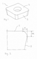
- the value "ER" is equal to the distance between the intersection point between the first and the second plane and the point of contact between the first plane and the cutting tool, close to the edge, see Fig. 2 .
- Shot blasting is herein denoted a process using abrasive grains wherein material typically is removed from the treated surface by abrasive wear. Shot blasting is well known in the field of cutting tools and is for example known to introduce residual stresses in a coating on a cutting tool.
- Hot peening is herein meant that the surface of a cutting tool is bombarded with a media comprising particles, so called beads, that are non-abrasive and that typically have a round shape.
- the media can be beads of a hard material such as an oxide, steel or cemented carbide.
- the innermost part (centre) of the cutting tool and for this disclosure is the zone having the lowest hardness.
- surface area is herein meant the outer portion of the substrate which is influenced by the shot peening process disclosed herein.
- Fig. 1 is a general view of a cutting tool insert 1, provided with a rake face 2 and a flank face 3. A cutting edge is provided therebetween.
- Fig. 2 is a general view of a cross section of a cutting edge wherein the ER is indicated and also the width of the cutting edge, "w", is shown schematically.
- the present invention relates to a method of treating a cutting tool 1 comprising a cemented carbide or cermet substrate wherein the cutting tool is subjected to shot peening at a temperature of or above 100°C, preferably at a temperature of or above 200°C, more preferably at a temperature of between 200°C and 450°C.
- the portion of the substrate that is subjected to shot peening is at said temperature. It has unexpectedly been found that treating a cutting tool to shot peening when it is heated increases its lifetime in cutting.
- the upper limit for the temperature where the shot peening is performed is preferably below the sintering temperature for the given cemented carbide or cermet, more preferably below 1200°C.
- the shot peening of the present invention is performed at an elevated temperature, and this temperature is herein defined as the temperature that the material (the portion of the cutting tool) that is shot peened is at during the shot peening.
- This temperature is herein defined as the temperature that the material (the portion of the cutting tool) that is shot peened is at during the shot peening.
- Several methods can be used to create the elevated temperature of the cutting tool portion, such as induction heating, resistance heating, pre-heating on a hot surface/oven, laser heating etc.
- the cutting tool can alternatively be heated in a separate step prior to the shot peening step.
- the temperature is suitably measured on the substrate by any method suitable for measuring temperature.
- an infrared temperature measurement device is used.
- the cutting tool 1 comprises a rake face 2, a flank face 3 and a cutting edge there between, and wherein said shot peening is performed at least on the rake face 2.
- Rake face peening is advantageous in that it is at the rake face 2 that the working material hits the cutting tool during the cutting operation and that the mechanisms during peening that is influencing the substrate is therefore applied at a relevant area or volume of the substrate. It is further advantageous to apply the shot peening at the rake face 2 since for many cutting tool geometries this imply treating several cutting edges at the same time.
- an ER of at least a part of said cutting edge is between 10 ⁇ m and 50 ⁇ m, preferably between 20 ⁇ m and 40 ⁇ m. It has surprisingly been shown that the present method is performing well on cutting tools 1 with this ER.
- the metallic binder phase content in the cemented carbide or cermet is 1-30 vol%, preferably 3-25 vol%.
- the binder phase content is to be high enough to provide a tough behaviour of the cutting edge.
- the metallic binder phase content is preferably not higher than 30 vol%, preferably not higher than 25 vol%. A too high content of binder phase reduces the hardness and wear resistance of the cutting tool.
- the metallic binder phase is an alloy comprising at least 80 wt% of one or more metallic elements selected from Co, Ni and Fe.
- the metallic binder phase is an alloy comprising one or more metallic elements selected from Co, Ni, Fe, Al, Cr, Ru, W, Mo, Mn, Re, Ti, Ta, Nb, Zr, Hf, Cu, Si.
- the cutting tool is provided with a coating.
- the coating can be a colour layer or a wear resistant coating.
- the thickness of the coating is 1.5-25 ⁇ m, preferably 2-20 ⁇ m, more preferably 2-10 ⁇ m.
- the shot peening is preferably performed in a dry process using air with the beads in it.
- the beads can be made of any material known in the art of shot peening, such as ceramic beads, cemented carbide beads or metallic beads.
- the shot peening is performed with a peening media comprising beads of ZrO 2 , steel or cemented carbide.
- the shot peening is performed with a peening media of an average diameter of 70-150 ⁇ m.
- the impact or energy from the beads during the shot peening should not be too high since this would increase the risk of damaging the surface and the cutting edge of the cutting tool.
- the impact or energy from the beads should neither be too low since then the technical effect would not be achieved. If the beads are too large the risk of damaging the cutting edge is increased. If the beads are too small the energy and impact transferred from the media to the substrate is less pronounced.
- a suitable size of the beads is related to the material of the beads and is to be selected by the skilled person.
- the coating is a CVD coating or a PVD coating, preferably said coating comprising one or more layers selected from TiN, TiCN, TiC, TiAIN, Al 2 O 3 and ZrCN.
- the coated cutting tool subjected to the shot peening process according to the present invention can be provided with any coating common in the art of cutting tools, suitably a PVD or CVD coating, preferably a CVD coating.
- the coating is a CVD coating comprising an inner TiCN layer and an outer ⁇ -Al 2 O 3 layer.
- the cemented carbide substrate is provided with a wear resistant PVD coating, suitably being a nitride, oxide, carbide or mixtures thereof of one or more of the elements selected from Al, Si and groups 4, 5 and 6 in the periodic table.
- a wear resistant PVD coating suitably being a nitride, oxide, carbide or mixtures thereof of one or more of the elements selected from Al, Si and groups 4, 5 and 6 in the periodic table.
- the shot peening is performed on heated cutting tools
- the method comprises a step prior to the shot peening wherein said cutting tools are heated.
- the method further comprises a step of shot blasting at least a portion of the cutting tool.
- the portion includes at least a section of the cutting edge or an area close to the cutting edge.
- the step of shot blasting is performed subsequent to the shot peening.
- the heat during the shot peening can reduce some positive effect from the shot blasting, such as residual stress induction in a coating, so by selecting to do the shot peening before the shot blasting both positive effects can be maintained.
- the shot blasting and the shot peening are performed on the same portions of the cutting tool. This is advantageous for example during a production in large scale due to a more effective loading of the cutting tools.
- the peening is performed in a shot direction that is perpendicular to the surface of the cutting tool.
- a perpendicular shot peening is advantageous in that the depth of the impacted substrate is the largest when the heated shot peening is in this direction.
- the cutting tool 1 is an insert, preferably a milling insert.
- the cemented carbide has a binder phase of Co, preferably 3-20 wt% Co in the cemented carbide, and wherein the cemented carbide comprises Cr, preferably with a Cr/Co weight ratio of 0.03-0.35, more preferably a Cr/Co weight ratio of 0.07-0.20.
- the cemented carbide comprises M 7 C 3 carbides.
- the cemented carbide has a substoichiometric carbon content, SCC, of -0.13 wt% ⁇ SCC ⁇ 0 wt%, or -0.30 wt%% ⁇ SCC ⁇ -0.16wt%.
- the cemented carbide has a substoichiometric carbon content, SCC, of -0.28 wt% ⁇ SCC ⁇ -0.17 wt%, and further comprises eta phase.
- the shot peening process according to the present invention can also be combined with other process steps known in the art of making cutting tools such e.g. brushing, polishing, wet blasting, dry blasting etc.
- the present invention also relates to a cutting tool 1 treated with the method of the present invention.
- Cutting tools of cemented carbide were prepared by forming substrates from raw materials according to table 1.
- the substrates were manufactured according to conventional methods including milling, spray drying, pressing and sintering.
- Cutting tools of the Insert type R390-11T308M-PM and R390-11T308M-MM were formed and used in the milling tests.
- Also cutting tools of Insert type SNUN 19 04 16 were formed and these were used in the hardness and the residual stress measurements. Tungsten metal was added to substrate 3A and 3B in order to adjust the carbon content.
- the amount of eta phase in substrates 1A, 3A and 3B were determined by image analysis using the software Image J using the setup "Automatic".
- the images used for the analysis was LOM images with a magnification of 1000X and 2000X, two measurements were done at each magnification and the value presented below is an average value of these. The value is an average from a total of four image analyses performed on two images, 2 measurements on each image.
- the substrate 3A contained 4 vol% eta phase
- substrates 1A and 3B contained no eta phase.
- the substoichiometric carbon content (SCC) was calculated for substrates 1A, 3A and 3B. and are presented in Table 1. None of the substrate contained free graphite. Except for the substrate 3A, none of the other substrate contained eta phase in the bulk area of the substrate.
- Substrates 1A, 1B, 2A, 2B, 2C, 2D, 3A, and 3B were coated in the same coating process, depositing the layers TiN/TiCN/ ⁇ -Al 2 O 3 /TiN with CVD.
- the total coating thickness was about 6.6 ⁇ m.
- Substrate 1C was coated in a coating process, depositing the layers TiN/TiCN/ ⁇ -Al 2 O 3 /TiN with CVD.
- the total coating thickness was about 4.2 ⁇ m.
- the shot peening of the samples later tested in Example 2 was performed in a IEPCO Micropeen Peenmatic 750 GSD equipment.
- a blasting media of ZrO 2 ceramic beads with a spherical shape and an average diameter of about 100 ⁇ m was used, media IEPCO MS/Z 350 B.
- the grain size of the ZrOz ceramic beads is 70-125 ⁇ m.
- the shot gun pressure was set to 5 bar, the working time was set to 20 seconds, the nozzle diameter was 8 mm and the stand-off distance was 100 mm.
- the peening was applied perpendicular to the rake face of the cutting tools. In the case of heated shot peening the cutting tools were heated at a resistance heater prior to the shot peening and the temperature of the cutting tools were measured with a temperature sensor.
- the shot peening of the samples later tested in Examples 3 and 4 was performed in an AUER Manual Blasting Cabinet ST 700 PS equipment.
- a blasting media of ZrO 2 ceramic beads with a spherical shape and an average diameter of about 100 ⁇ m was used, media Microblast ® B120.
- the grain size of the ZrO 2 ceramic beads is 63-125 ⁇ m.
- the shot gun pressure was set to 2 bar, the working time was set to 12 seconds, the nozzle diameter was 8 mm and the stand-off distance was 100 mm.
- the peening was applied perpendicular to the rake face of the cutting tools.
- the cutting tools were heated with an induction coil heater prior to the shot peening and the temperature of the cutting tools were measured with a temperature sensor.
- the induction heater was a Rimac induction heater, 1.5 kW.
- the shot blasting was performed with Al 2 O 3 abrasive grains with a grain size of F220.
- the concentration of blasting media in water was 20 vol% and the pump pressure during blasting was 1.8 bar.
- the blasting pressure was 2.0 bar, the time of blasting per area was about 5 seconds and the direction of the blasting was perpendicular to the rake face of the cutting tools.
- the distance between the shot gun and the samples (cutting tools) was about 130 mm.
- the cutting tools 1C were instead edge line brushed before the shot peening.
- coated cutting tools according to the above that were only shot blasted or only edge brushed, i.e. not shot peened, were prepared and are hereinafter called Reference 1, Reference 2 and Reference 3.
- the cutting edges of the of the cutting tools after these post-treatments are about ER 40 ⁇ m.
- the tool life criterion was set to chipping of at least 0.5 mm of the edge line. Tool life is presented as the average number of cut entrances in order to achieve these criteria. The average tool life is presented in Table 2 and the tool life is the average number of cuts and it is an average of 8 parallel cutting test. Table 2.
- Example 2 Name of sample Substrate Shot peening Average tool life Invention 1A 1A at 200°C 25 Comparative 1A 1A at 25°C 19 Reference 1A 1A no shot peening 9 Invention 2A 2A at 200°C 85 Comparative 2A 2A at 25°C 32 Reference 2A 2A no shot peening 10 Invention 3A 3A at 200°C 83 Comparative 3A 3A at 25°C 61 Reference 3A 3A no shot peening 8
- the tool life criterion was set to chipping of at least 0.5 mm of the edge line. Tool life is presented as the average number of cuts in order to achieve this criteria. The presented average tool life is presented in Table 3 and the tool life is the average number of cuts of 8 parallel cutting test. Table 3.
- Example 3 Name of sample Substrate Shot peening at temperature [°C] Average tool life Comparative 1B 1B 25°C 12.2 Invention 1B 1B 300°C 16.6 Comparative 2A 2A 25°C 7.8 Invention 2A 2A 300°C 12.5 Comparative 2B 2B 25°C 5.4 Invention 2B 2B 300°C 14.2 Comparative 2C 2C 25°C 7.0 Invention 2C 2C 300°C 11.2 Comparative 2D 2D 25°C 11.0 Invention 2D 2D 300°C 19.3 Comparative 3A 3A 25°C 10.7 Invention 3A 3A 300°C 17.1 Comparative 3B 3B 25°C 16.2 Invention 3B 3B 300°C 30
- edge line toughness inserts were prepared, and in this case the shot peeing was performed at 2 bar and for 12 seconds. The inserts were then tested in a milling operation at the following parameters:
- the tool life criterion was set to chipping of at least 0.5 mm of the edge line. Tool life is presented as the average number of cut entrances in order to achieve these criteria. The presented average number of cuts is an average of 16 parallel cutting test and the average tool life is presented in Table 4. Table 4. Summary of cutting test results of Example 4 Name of sample Substrate No.
- Samples were polished using standard methods so that the TiCN layer was exposed on the rake face of the cutting tool.
- a bulk sample was prepared by cutting the insert perpendicular to the rake face using a diamond wheel and subsequently polishing using 9 ⁇ m diamond dispersed in oil on paper and then 1 ⁇ m diamond dispersed in oil. Hardness of the polished samples were then measured using a programmable hardness tester, KB30S by KB pronouncetechnik GmbH. The measurements were calibrated against HV100 using test blocks issued by Euro Products Calibration Laboratory, UK. Hardness was measured according to ISO EN6507.
- HV measurements were performed by programming the hardness tester to perform indentations at certain positions. Indentations are then performed using the specified load after which each indentation is automatically revisited.
- the computer auto adjusts light, auto focuses and then measures the size of each indentation, a photo is saved and the user inspects all the photos of the indentations for focus and other matters that might disturb the result.
- Four parallel HV100 indentations were made with a distance from each other (center-center) of about 1.5 mm and the presented result is an average value.
- X-ray diffraction was used to determine residual stresses in the aforementioned samples through the so-called sin 2 ⁇ - method.
- the shift of lattice spacings d (and hence the strains) are measured as a function of sample tilt angles ⁇ .
- the residual stresses are obtained from the linear slope of the strain vs sin 2 ⁇ curve. Residual stresses are converted from strain values by using X-ray elastic constants.
- the (2 11) reflection of WC located at 117.32° 2 ⁇ was used for strain measurements.
- the residual stress measurements were performed in 1 to 4 angular directions, ⁇ : 0°, 90°, 180°, 270° and for each ⁇ -direction 10 equidistant ⁇ -angles (0° - 50°) were measured, measurement time 400 s.
- a collimator with 1.0 mm diameter was used in all measurements.
- the resulting residual stresses were obtained from strain data by using X-ray elastic constants for WC, Bragg peak (211).
- the samples were mounted with adhesive tape to the sample holder.
- the XRD data were analyzed with software DIFFRAC EVA (Bruker) and High Score Plus (Malvern Panalytical).
- Software LEPTOS 7 (Bruker) was used in the residual stress analysis.
- the samples were heat treated at 400°C for 10 minutes at atmospheric pressure in an oven and in a flow of Ar gas.
Landscapes
- Engineering & Computer Science (AREA)
- Mechanical Engineering (AREA)
- Chemical & Material Sciences (AREA)
- Materials Engineering (AREA)
- Metallurgy (AREA)
- Organic Chemistry (AREA)
- Crystallography & Structural Chemistry (AREA)
- Chemical Kinetics & Catalysis (AREA)
- Cutting Tools, Boring Holders, And Turrets (AREA)
Applications Claiming Priority (5)
| Application Number | Priority Date | Filing Date | Title |
|---|---|---|---|
| EP18180803 | 2018-06-29 | ||
| EP18180763 | 2018-06-29 | ||
| EP18180801 | 2018-06-29 | ||
| PCT/EP2019/067455 WO2020002664A1 (en) | 2018-06-29 | 2019-06-28 | Method of treating a cutting tool, and a cutting tool |
| EP19733080.6A EP3814051B1 (de) | 2018-06-29 | 2019-06-28 | Verfahren zur behandlung eines schneidwerkzeugs und ein schneidwerkzeug |
Related Parent Applications (1)
| Application Number | Title | Priority Date | Filing Date |
|---|---|---|---|
| EP19733080.6A Division EP3814051B1 (de) | 2018-06-29 | 2019-06-28 | Verfahren zur behandlung eines schneidwerkzeugs und ein schneidwerkzeug |
Publications (2)
| Publication Number | Publication Date |
|---|---|
| EP4458499A2 true EP4458499A2 (de) | 2024-11-06 |
| EP4458499A3 EP4458499A3 (de) | 2025-06-25 |
Family
ID=67003529
Family Applications (2)
| Application Number | Title | Priority Date | Filing Date |
|---|---|---|---|
| EP24195197.9A Pending EP4458499A3 (de) | 2018-06-29 | 2019-06-28 | Verfahren zur behandlung eines schneidwerkzeugs und ein schneidwerkzeug |
| EP19733080.6A Active EP3814051B1 (de) | 2018-06-29 | 2019-06-28 | Verfahren zur behandlung eines schneidwerkzeugs und ein schneidwerkzeug |
Family Applications After (1)
| Application Number | Title | Priority Date | Filing Date |
|---|---|---|---|
| EP19733080.6A Active EP3814051B1 (de) | 2018-06-29 | 2019-06-28 | Verfahren zur behandlung eines schneidwerkzeugs und ein schneidwerkzeug |
Country Status (6)
| Country | Link |
|---|---|
| US (2) | US12420340B2 (de) |
| EP (2) | EP4458499A3 (de) |
| JP (1) | JP2021529676A (de) |
| CN (1) | CN112313037A (de) |
| BR (1) | BR112020026714B1 (de) |
| WO (1) | WO2020002664A1 (de) |
Families Citing this family (8)
| Publication number | Priority date | Publication date | Assignee | Title |
|---|---|---|---|---|
| EP4458499A3 (de) * | 2018-06-29 | 2025-06-25 | AB Sandvik Coromant | Verfahren zur behandlung eines schneidwerkzeugs und ein schneidwerkzeug |
| US20220176472A1 (en) * | 2018-08-02 | 2022-06-09 | Us Synthetic Corporation | Cutting tool with pcd inserts, systems incorporating same and related methods |
| EP3835018A1 (de) * | 2019-12-12 | 2021-06-16 | Ceratizit Luxembourg Sàrl | Schneidelement und verwendung davon |
| GB2590936B (en) * | 2020-01-07 | 2024-03-06 | Vapormatt Ltd | Treatment machine and method of improving a cutting edge |
| WO2022004523A1 (ja) * | 2020-06-30 | 2022-01-06 | 京セラ株式会社 | 被覆工具の製造方法 |
| CN112853188A (zh) * | 2020-12-31 | 2021-05-28 | 株洲硬质合金集团有限公司 | 一种硬质合金及其制备方法和应用 |
| CN113322468B (zh) * | 2021-05-25 | 2023-03-28 | 合肥学院 | 一种提高钛锆基合金耐磨性的表面强化方法 |
| EP4098770A1 (de) * | 2021-06-02 | 2022-12-07 | Pramet Tools, S.R.O. | Beschichtetes schneidwerkzeug |
Family Cites Families (44)
| Publication number | Priority date | Publication date | Assignee | Title |
|---|---|---|---|---|
| US3573023A (en) * | 1968-09-24 | 1971-03-30 | Ingersoll Rand Co | Methods for improving hardness and strength of ceramic materials |
| US4674365A (en) * | 1983-07-27 | 1987-06-23 | Spectra Products Corporation | Method for extending the life of a cutting tool |
| JPS61264105A (ja) | 1985-05-17 | 1986-11-22 | Toyota Motor Corp | 高強度焼結部材の製造方法 |
| JP3049165B2 (ja) * | 1993-02-15 | 2000-06-05 | 株式会社不二製作所 | 粉末合金の表面層の処理法 |
| US5597272A (en) * | 1994-04-27 | 1997-01-28 | Sumitomo Electric Industries, Ltd. | Coated hard alloy tool |
| JP3689925B2 (ja) * | 1995-01-10 | 2005-08-31 | 住友電気工業株式会社 | 被覆硬質材料及びその製造方法 |
| JP3419154B2 (ja) * | 1995-06-27 | 2003-06-23 | 住友電気工業株式会社 | 切削工具部材及びその製造方法 |
| US6544360B1 (en) * | 1999-06-08 | 2003-04-08 | Nhk Spring Co., Ltd. | Highly strengthened spring and process for producing the same |
| JP3984128B2 (ja) * | 2002-09-02 | 2007-10-03 | 住友電工ハードメタル株式会社 | 切削工具 |
| JPWO2004085685A1 (ja) * | 2003-03-26 | 2006-06-29 | 中央発條株式会社 | 高強度ばねの製造方法 |
| SE527906C2 (sv) * | 2004-06-24 | 2006-07-04 | Sandvik Intellectual Property | Belagt hårdmetallskär speciellt avsett för svarvning av rostfritt stål |
| US7244519B2 (en) * | 2004-08-20 | 2007-07-17 | Tdy Industries, Inc. | PVD coated ruthenium featured cutting tools |
| ES2524326T3 (es) * | 2004-08-26 | 2014-12-05 | Daido Tokushuko Kabushiki Kaisha | Resorte de alta resistencia y método para la fabricación del mismo |
| US8012611B2 (en) * | 2004-10-29 | 2011-09-06 | Sumitomo Electric Hardmetal Corp. | Surface-coated cutting tool |
| US7972714B2 (en) * | 2004-12-14 | 2011-07-05 | Sumitomo Electric Hardmetal Corp. | Coated cutting tool |
| JP2006181645A (ja) * | 2004-12-24 | 2006-07-13 | Sumitomo Electric Hardmetal Corp | 表面被覆切削工具 |
| KR20070114719A (ko) * | 2005-03-29 | 2007-12-04 | 스미또모 덴꼬오 하드메탈 가부시끼가이샤 | 날끝 교환형 절삭 팁 및 그 제조 방법 |
| JP4779611B2 (ja) * | 2005-12-02 | 2011-09-28 | 三菱マテリアル株式会社 | 表面被覆切削インサートの製造方法 |
| JP2007284751A (ja) * | 2006-04-18 | 2007-11-01 | Hitachi Tool Engineering Ltd | 微粒超硬合金 |
| DE102006046263B3 (de) * | 2006-09-28 | 2008-04-03 | Fraunhofer-Gesellschaft zur Förderung der angewandten Forschung e.V. | Verfahren zur Erhöhung der Bruchzähigkeit der Randschicht einer Hartmetallschneide eines Bohrers |
| JP2008207279A (ja) * | 2007-02-27 | 2008-09-11 | Sanyo Special Steel Co Ltd | 金型の表面改質方法および金型 |
| GB0903343D0 (en) * | 2009-02-27 | 2009-04-22 | Element Six Holding Gmbh | Hard-metal body with graded microstructure |
| JP5393280B2 (ja) * | 2009-06-17 | 2014-01-22 | 日本発條株式会社 | 車両懸架用コイルばねと、その製造方法 |
| JP5510637B2 (ja) * | 2009-10-21 | 2014-06-04 | 三菱マテリアル株式会社 | 炭窒化チタン基サーメット製切削インサートおよびその製造方法 |
| WO2011122554A1 (ja) * | 2010-03-29 | 2011-10-06 | 京セラ株式会社 | 切削工具 |
| JP5124793B2 (ja) * | 2010-07-16 | 2013-01-23 | 住友電工ハードメタル株式会社 | 表面被覆切削工具 |
| US9566649B2 (en) * | 2011-09-22 | 2017-02-14 | Tungaloy Corporation | Coated cutting tool |
| JP5858363B2 (ja) * | 2012-05-24 | 2016-02-10 | 住友電工ハードメタル株式会社 | 切削工具用の基材およびそれを含む表面被覆切削工具 |
| DE102012107129A1 (de) * | 2012-08-03 | 2014-02-06 | Walter Ag | TiAIN-beschichtetes Werkzeug |
| GB201309798D0 (en) | 2013-05-31 | 2013-07-17 | Element Six Abrasives Sa | Superhard constructions & methods of making same |
| CN103358234B (zh) * | 2013-07-19 | 2015-09-30 | 山东海华汽车部件有限公司 | 一种簧片余热应力喷丸工艺 |
| JP5994948B2 (ja) * | 2013-11-08 | 2016-09-21 | 株式会社タンガロイ | 被覆切削工具 |
| GB201323169D0 (en) * | 2013-12-31 | 2014-02-12 | Element Six Abrasives Sa | Superhard constructions & methods of making same |
| WO2017108610A1 (en) * | 2015-12-21 | 2017-06-29 | Sandvik Intellectual Property Ab | Cutting tool |
| US10385415B2 (en) * | 2016-04-28 | 2019-08-20 | GM Global Technology Operations LLC | Zinc-coated hot formed high strength steel part with through-thickness gradient microstructure |
| US10273575B2 (en) | 2016-08-31 | 2019-04-30 | Kennametal Inc. | Composite refractory coatings and applications thereof |
| CA3036752C (en) * | 2016-09-28 | 2024-06-18 | Sandvik Intellectual Property Ab | A rock drill insert |
| JP6210346B1 (ja) * | 2016-11-02 | 2017-10-11 | 株式会社タンガロイ | 被覆切削工具 |
| JP6210347B1 (ja) * | 2016-11-04 | 2017-10-11 | 株式会社タンガロイ | 被覆切削工具 |
| JP6708261B2 (ja) * | 2016-11-14 | 2020-06-10 | 株式会社タンガロイ | 被覆切削工具 |
| EP4458499A3 (de) * | 2018-06-29 | 2025-06-25 | AB Sandvik Coromant | Verfahren zur behandlung eines schneidwerkzeugs und ein schneidwerkzeug |
| KR200490191Y1 (ko) | 2019-04-18 | 2019-10-08 | 이승훈 | 친환경 우산 빗물 제거기 |
| EP3838448A1 (de) * | 2019-12-20 | 2021-06-23 | Sandvik Mining and Construction Tools AB | Verfahren zur behandlung eines bergbaueinsatzes |
| EP3872222B1 (de) * | 2020-02-28 | 2022-12-28 | AB Sandvik Coromant | Beschichtetes schneidwerkzeug |
-
2019
- 2019-06-28 EP EP24195197.9A patent/EP4458499A3/de active Pending
- 2019-06-28 WO PCT/EP2019/067455 patent/WO2020002664A1/en not_active Ceased
- 2019-06-28 CN CN201980042789.8A patent/CN112313037A/zh active Pending
- 2019-06-28 US US17/252,994 patent/US12420340B2/en active Active
- 2019-06-28 EP EP19733080.6A patent/EP3814051B1/de active Active
- 2019-06-28 JP JP2020573133A patent/JP2021529676A/ja active Pending
- 2019-06-28 BR BR112020026714-7A patent/BR112020026714B1/pt active IP Right Grant
-
2025
- 2025-04-23 US US19/187,525 patent/US20250249515A1/en active Pending
Non-Patent Citations (1)
| Title |
|---|
| WANG ET AL.: "Effect of shot peening on the residual stresses and microstructure of tungsten cemented carbide", MATERIALS AND DESIGN, vol. 95, 2016, pages 159 - 164, XP029437401, DOI: 10.1016/j.matdes.2016.01.101 |
Also Published As
| Publication number | Publication date |
|---|---|
| EP3814051A1 (de) | 2021-05-05 |
| CN112313037A (zh) | 2021-02-02 |
| KR20210023861A (ko) | 2021-03-04 |
| US20250249515A1 (en) | 2025-08-07 |
| JP2021529676A (ja) | 2021-11-04 |
| US20210114116A1 (en) | 2021-04-22 |
| BR112020026714A2 (pt) | 2021-03-23 |
| BR112020026714B1 (pt) | 2024-01-30 |
| EP4458499A3 (de) | 2025-06-25 |
| WO2020002664A1 (en) | 2020-01-02 |
| EP3814051B1 (de) | 2024-09-18 |
| US12420340B2 (en) | 2025-09-23 |
Similar Documents
| Publication | Publication Date | Title |
|---|---|---|
| EP3814051B1 (de) | Verfahren zur behandlung eines schneidwerkzeugs und ein schneidwerkzeug | |
| EP2594352B1 (de) | Oberflächenbeschichtetes schneidewerkzeug | |
| EP2332678B1 (de) | Gesintertes hartmetall und schneidewerkzeug | |
| EP1997938A2 (de) | Beschichtetes Schneidewerkzeug | |
| US12370605B2 (en) | Cutting tool | |
| EP4076799B1 (de) | Schneidwerkzeug und verfahren zu seiner herstellung | |
| EP3421642B1 (de) | Beschichtetes schneidwerkzeug | |
| KR102896264B1 (ko) | 절삭 공구의 처리 방법 및 절삭 공구 | |
| US20230037096A1 (en) | Cutting tool | |
| EP4389321B1 (de) | Beschichtetes schneidwerkzeug | |
| JP7724413B2 (ja) | 被覆切削工具 |
Legal Events
| Date | Code | Title | Description |
|---|---|---|---|
| PUAI | Public reference made under article 153(3) epc to a published international application that has entered the european phase |
Free format text: ORIGINAL CODE: 0009012 |
|
| STAA | Information on the status of an ep patent application or granted ep patent |
Free format text: STATUS: THE APPLICATION HAS BEEN PUBLISHED |
|
| AC | Divisional application: reference to earlier application |
Ref document number: 3814051 Country of ref document: EP Kind code of ref document: P |
|
| AK | Designated contracting states |
Kind code of ref document: A2 Designated state(s): AL AT BE BG CH CY CZ DE DK EE ES FI FR GB GR HR HU IE IS IT LI LT LU LV MC MK MT NL NO PL PT RO RS SE SI SK SM TR |
|
| REG | Reference to a national code |
Ref country code: DE Ref legal event code: R079 Free format text: PREVIOUS MAIN CLASS: B23B0027140000 Ipc: B24C0001020000 |
|
| PUAL | Search report despatched |
Free format text: ORIGINAL CODE: 0009013 |
|
| AK | Designated contracting states |
Kind code of ref document: A3 Designated state(s): AL AT BE BG CH CY CZ DE DK EE ES FI FR GB GR HR HU IE IS IT LI LT LU LV MC MK MT NL NO PL PT RO RS SE SI SK SM TR |
|
| RIC1 | Information provided on ipc code assigned before grant |
Ipc: C23C 14/00 20060101ALI20250520BHEP Ipc: C22C 29/08 20060101ALI20250520BHEP Ipc: B23P 15/28 20060101ALI20250520BHEP Ipc: B23P 9/04 20060101ALI20250520BHEP Ipc: B23B 27/14 20060101ALI20250520BHEP Ipc: B24C 1/10 20060101ALI20250520BHEP Ipc: B24C 1/02 20060101AFI20250520BHEP |