EP4458484A1 - Verfahren zum biegen und bearbeiten von werkstücken an einer werkzeugmaschine sowie werkzeugmaschine zum bearbeiten und biegen von werkstücken - Google Patents
Verfahren zum biegen und bearbeiten von werkstücken an einer werkzeugmaschine sowie werkzeugmaschine zum bearbeiten und biegen von werkstücken Download PDFInfo
- Publication number
- EP4458484A1 EP4458484A1 EP23171049.2A EP23171049A EP4458484A1 EP 4458484 A1 EP4458484 A1 EP 4458484A1 EP 23171049 A EP23171049 A EP 23171049A EP 4458484 A1 EP4458484 A1 EP 4458484A1
- Authority
- EP
- European Patent Office
- Prior art keywords
- bending
- workpiece
- tool
- working unit
- machine tool
- Prior art date
- Legal status (The legal status is an assumption and is not a legal conclusion. Google has not performed a legal analysis and makes no representation as to the accuracy of the status listed.)
- Pending
Links
Images


Classifications
-
- B—PERFORMING OPERATIONS; TRANSPORTING
- B21—MECHANICAL METAL-WORKING WITHOUT ESSENTIALLY REMOVING MATERIAL; PUNCHING METAL
- B21D—WORKING OR PROCESSING OF SHEET METAL OR METAL TUBES, RODS OR PROFILES WITHOUT ESSENTIALLY REMOVING MATERIAL; PUNCHING METAL
- B21D7/00—Bending rods, profiles, or tubes
- B21D7/02—Bending rods, profiles, or tubes over a stationary forming member; by use of a swinging forming member or abutment
- B21D7/024—Bending rods, profiles, or tubes over a stationary forming member; by use of a swinging forming member or abutment by a swinging forming member
-
- B—PERFORMING OPERATIONS; TRANSPORTING
- B21—MECHANICAL METAL-WORKING WITHOUT ESSENTIALLY REMOVING MATERIAL; PUNCHING METAL
- B21D—WORKING OR PROCESSING OF SHEET METAL OR METAL TUBES, RODS OR PROFILES WITHOUT ESSENTIALLY REMOVING MATERIAL; PUNCHING METAL
- B21D7/00—Bending rods, profiles, or tubes
- B21D7/04—Bending rods, profiles, or tubes over a movably-arranged forming menber
-
- B—PERFORMING OPERATIONS; TRANSPORTING
- B21—MECHANICAL METAL-WORKING WITHOUT ESSENTIALLY REMOVING MATERIAL; PUNCHING METAL
- B21D—WORKING OR PROCESSING OF SHEET METAL OR METAL TUBES, RODS OR PROFILES WITHOUT ESSENTIALLY REMOVING MATERIAL; PUNCHING METAL
- B21D7/00—Bending rods, profiles, or tubes
- B21D7/06—Bending rods, profiles, or tubes in press brakes or between rams and anvils or abutments; Pliers with forming dies
-
- B—PERFORMING OPERATIONS; TRANSPORTING
- B21—MECHANICAL METAL-WORKING WITHOUT ESSENTIALLY REMOVING MATERIAL; PUNCHING METAL
- B21D—WORKING OR PROCESSING OF SHEET METAL OR METAL TUBES, RODS OR PROFILES WITHOUT ESSENTIALLY REMOVING MATERIAL; PUNCHING METAL
- B21D11/00—Bending not restricted to forms of material mentioned in only one of groups B21D5/00, B21D7/00, B21D9/00; Bending not provided for in groups B21D5/00 - B21D9/00; Twisting
- B21D11/08—Bending by altering the thickness of part of the cross-section of the work
-
- B—PERFORMING OPERATIONS; TRANSPORTING
- B21—MECHANICAL METAL-WORKING WITHOUT ESSENTIALLY REMOVING MATERIAL; PUNCHING METAL
- B21D—WORKING OR PROCESSING OF SHEET METAL OR METAL TUBES, RODS OR PROFILES WITHOUT ESSENTIALLY REMOVING MATERIAL; PUNCHING METAL
- B21D37/00—Tools as parts of machines covered by this subclass
- B21D37/04—Movable or exchangeable mountings for tools
-
- B—PERFORMING OPERATIONS; TRANSPORTING
- B21—MECHANICAL METAL-WORKING WITHOUT ESSENTIALLY REMOVING MATERIAL; PUNCHING METAL
- B21D—WORKING OR PROCESSING OF SHEET METAL OR METAL TUBES, RODS OR PROFILES WITHOUT ESSENTIALLY REMOVING MATERIAL; PUNCHING METAL
- B21D7/00—Bending rods, profiles, or tubes
- B21D7/12—Bending rods, profiles, or tubes with program control
-
- B—PERFORMING OPERATIONS; TRANSPORTING
- B21—MECHANICAL METAL-WORKING WITHOUT ESSENTIALLY REMOVING MATERIAL; PUNCHING METAL
- B21D—WORKING OR PROCESSING OF SHEET METAL OR METAL TUBES, RODS OR PROFILES WITHOUT ESSENTIALLY REMOVING MATERIAL; PUNCHING METAL
- B21D7/00—Bending rods, profiles, or tubes
- B21D7/14—Bending rods, profiles, or tubes combined with measuring of bends or lengths
-
- B—PERFORMING OPERATIONS; TRANSPORTING
- B23—MACHINE TOOLS; METAL-WORKING NOT OTHERWISE PROVIDED FOR
- B23Q—DETAILS, COMPONENTS, OR ACCESSORIES FOR MACHINE TOOLS, e.g. ARRANGEMENTS FOR COPYING OR CONTROLLING; MACHINE TOOLS IN GENERAL CHARACTERISED BY THE CONSTRUCTION OF PARTICULAR DETAILS OR COMPONENTS; COMBINATIONS OR ASSOCIATIONS OF METAL-WORKING MACHINES, NOT DIRECTED TO A PARTICULAR RESULT
- B23Q39/00—Metal-working machines incorporating a plurality of sub-assemblies, each capable of performing a metal-working operation
- B23Q39/02—Metal-working machines incorporating a plurality of sub-assemblies, each capable of performing a metal-working operation the sub-assemblies being capable of being brought to act at a single operating station
- B23Q39/021—Metal-working machines incorporating a plurality of sub-assemblies, each capable of performing a metal-working operation the sub-assemblies being capable of being brought to act at a single operating station with a plurality of toolheads per workholder, whereby the toolhead is a main spindle, a multispindle, a revolver or the like
- B23Q39/025—Metal-working machines incorporating a plurality of sub-assemblies, each capable of performing a metal-working operation the sub-assemblies being capable of being brought to act at a single operating station with a plurality of toolheads per workholder, whereby the toolhead is a main spindle, a multispindle, a revolver or the like with different working directions of toolheads on same workholder
- B23Q39/026—Metal-working machines incorporating a plurality of sub-assemblies, each capable of performing a metal-working operation the sub-assemblies being capable of being brought to act at a single operating station with a plurality of toolheads per workholder, whereby the toolhead is a main spindle, a multispindle, a revolver or the like with different working directions of toolheads on same workholder simultaneous working of toolheads
-
- B—PERFORMING OPERATIONS; TRANSPORTING
- B23—MACHINE TOOLS; METAL-WORKING NOT OTHERWISE PROVIDED FOR
- B23Q—DETAILS, COMPONENTS, OR ACCESSORIES FOR MACHINE TOOLS, e.g. ARRANGEMENTS FOR COPYING OR CONTROLLING; MACHINE TOOLS IN GENERAL CHARACTERISED BY THE CONSTRUCTION OF PARTICULAR DETAILS OR COMPONENTS; COMBINATIONS OR ASSOCIATIONS OF METAL-WORKING MACHINES, NOT DIRECTED TO A PARTICULAR RESULT
- B23Q39/00—Metal-working machines incorporating a plurality of sub-assemblies, each capable of performing a metal-working operation
- B23Q39/04—Metal-working machines incorporating a plurality of sub-assemblies, each capable of performing a metal-working operation the sub-assemblies being arranged to operate simultaneously at different stations, e.g. with an annular work-table moved in steps
- B23Q39/042—Metal-working machines incorporating a plurality of sub-assemblies, each capable of performing a metal-working operation the sub-assemblies being arranged to operate simultaneously at different stations, e.g. with an annular work-table moved in steps with circular arrangement of the sub-assemblies
- B23Q39/044—Metal-working machines incorporating a plurality of sub-assemblies, each capable of performing a metal-working operation the sub-assemblies being arranged to operate simultaneously at different stations, e.g. with an annular work-table moved in steps with circular arrangement of the sub-assemblies having at least one tool station cooperating with each work holder, e.g. multi-spindle lathes
-
- B—PERFORMING OPERATIONS; TRANSPORTING
- B23—MACHINE TOOLS; METAL-WORKING NOT OTHERWISE PROVIDED FOR
- B23Q—DETAILS, COMPONENTS, OR ACCESSORIES FOR MACHINE TOOLS, e.g. ARRANGEMENTS FOR COPYING OR CONTROLLING; MACHINE TOOLS IN GENERAL CHARACTERISED BY THE CONSTRUCTION OF PARTICULAR DETAILS OR COMPONENTS; COMBINATIONS OR ASSOCIATIONS OF METAL-WORKING MACHINES, NOT DIRECTED TO A PARTICULAR RESULT
- B23Q39/00—Metal-working machines incorporating a plurality of sub-assemblies, each capable of performing a metal-working operation
- B23Q2039/004—Machines with tool turrets
-
- B—PERFORMING OPERATIONS; TRANSPORTING
- B23—MACHINE TOOLS; METAL-WORKING NOT OTHERWISE PROVIDED FOR
- B23Q—DETAILS, COMPONENTS, OR ACCESSORIES FOR MACHINE TOOLS, e.g. ARRANGEMENTS FOR COPYING OR CONTROLLING; MACHINE TOOLS IN GENERAL CHARACTERISED BY THE CONSTRUCTION OF PARTICULAR DETAILS OR COMPONENTS; COMBINATIONS OR ASSOCIATIONS OF METAL-WORKING MACHINES, NOT DIRECTED TO A PARTICULAR RESULT
- B23Q39/00—Metal-working machines incorporating a plurality of sub-assemblies, each capable of performing a metal-working operation
- B23Q2039/008—Machines of the lathe type
Definitions
- the present application relates to a machine tool, in particular a turning or a milling machine, with which it is possible to both, machine and bend workpieces.
- Machine tools such as for example a turning or milling machines or lathes for machining a workpiece typically comprises a machine frame that is provided with at least one rotatably mounted work spindle for receiving workpieces and machining said workpieces using respective tool.
- Various configurations of working units can be implemented for machining of workpieces.
- For bending operations commonly specific bending machines are used. Accordingly, the bending machines are usually designed for bending operations and machine tools are designed for machining and these machines are commonly provided separately from each other. Therefore, for complex products which require both, bending and machining steps with several iterations of machining and bending operations, the production of a workpiece may be inefficient.
- JP 2020 032528 A which describes a machine tool which comprises a machine frame having an upper tool carrier support part, a lower tool carrier support part, and a spindle carrier part arranged between the upper tool carrier support part and the lower tool carrier support part; a spindle carrier arranged on or at a height of the spindle carrier part of the machine frame, the spindle carrier supporting a main spindle which receives a work-piece and is horizontally arranged; and one or more tool carriers each of which is supported on a tool carrier assembly arranged in an either of the upper tool carrier support part and the lower tool carrier support part of the machine frame.
- a lower side surface of the lower tool carrier support part has an overhung inclination.
- the content of this application is herewith incorporated by reference in its entirety.
- a bending machine is described in e.g. JP 2005 161331A which describes a bending machine.
- the bending machine is provided with a bending die, a fixing tool to fix the workpiece to the bending die, a pressure die to press the work against the bending die, and a restraining tool.
- the prior art focuses either on machining or on bending operations/process performed by a respective machine.
- it is often required to relocate the workpiece from a machine tool to a bending machine for performing respective machining or bending operations (in particular using specific tube bending machines).
- This becomes even more complex if a sequence of several machining and bending operations on the workpiece are required. Consequently, manufacturing time and complexity are increased.
- a machine tool in particular a numerically controlled turning, milling, turn-mill machine or working machine, comprising for example a machine frame having preferably at least one linear movable tool carrier slide configured to carry a working unit, at least a first work spindle provided to receive a workpiece, a first working unit mounted onto the tool carrier slide, wherein the first working unit is preferably configured to be rotatable around a B-axis and the first working unit is further preferably configured to be movable linearly in or along a X-Z plane (i.e. along the X-direction and/or along the Z-direction), said X-Z plane being perpendicular to the B-axis.
- a machine frame having preferably at least one linear movable tool carrier slide configured to carry a working unit, at least a first work spindle provided to receive a workpiece, a first working unit mounted onto the tool carrier slide, wherein the first working unit is preferably configured to be rotatable around a B-axis and the first
- Said B-axis may be arranged to allow a rotation of the working unit of the machine tool or e.g. tool turret or a milling head that enables the work unit or head to perform work from various angles on the side or end of a part held in a main or subspindle (or auxiliary spindle).
- the first working unit may have a (preferably integrated) bending tool and for performing a bending operation the first working unit may be configured to bend the workpiece received by the first work spindle by rotating around the B-axis and/or moving linearly along the X-Z plane.
- The, X-Y-Z coordinate system that is referred to herein, is preferably defined such that the Z-axis is a horizontal axis parallel or substantially parallel to a spindle axis (main spindle axis and/or auxiliary spindle axis) of the first work spindle, the Y-axis is a horizontal axis perpendicular to the Z-axis and the X-axis is the vertical axis perpendicular to the Y-Z plane.
- the B-axis and Y-axis are parallel to each other.
- a preferred bending operation is achieved by controlling a first working unit to rotate around the B axis and to move in the X-axis direction.
- a second working unit which is arranged opposite to the first working unit is thereby configured to move (e.g. linearly) in the Z axis direction (and most preferrable also the first work spindle may be configured to move in the Z axis direction) for achieving said bending motion, which is necessary for providing the bending operation.
- the machine tool may also be configured to rotate a first working unit around a B-axis and to move (e.g. linearly) a second working unit and/or the first working spindle in the Z-direction and preferably also in the X direction for achieving said bending motion, which is necessary for providing the bending operation.
- the machine tool may be configured for dual operation and therefore to perform bending and machining of at least one workpiece of the first work spindle at least successively and preferably in parallel.
- Parallel operation may include bending and machining the same workpiece at the same time.
- machining one workpiece and bending the other workpiece may also be allowed in order to achieve a parallel operation, i.e. at the same time. Unclamping the workpiece for machining after bending operation is therefore not necessary.
- the configuration allowing multi operation without unclamping the workpiece may also be referred to as dual operation in the clamped state of the workpiece. This feature enables more efficient manufacturing of the workpiece and also reduces the time required for manufacturing of the final workpiece.
- the machine tool may have a bending tool which includes at least a pressure die mounted on (or integrated into) the first working unit and wherein preferably the pressure die is mounted at a tool reception portion of the first working unit.
- the pressure die may be configured to move with the workpiece (which may be a tube or tubular workpiece) and may determine the point of bend.
- the workpiece may also be a workpiece having no hollow space on the inside, namely a full-body or solid-body, such as for example a cylinder or block.
- the machine tool may have a bending die which is connected to the machine frame and/or mounted on a second working unit of another movable tool carrier slide for additional support during bending of the workpiece, wherein the another movable tool carrier slide is configured to adjust the position of the bending die along its axis.
- the flexibility of the bending operation of the workpieces is further improved by using e.g. two working units which operate together to bend the workpiece.
- the bending die is a tool which allows workpieces to be bent around it and to define the resulting shape of the bent workpiece. Parameters of the bent workpiece and the bending machine may determine the type of bending die.
- the bending tools may be a tube bending die including detachable upper and lower bending rolls, an integrated clamp, and a pressure die.
- the bending rolls may have an elliptic curved shape.
- the integrated clamp may be arranged on sides of the upper and lower rolls.
- the press die may be formed into an elliptic curved shape.
- each tool carrier slide may be configured to independently move the respective working unit (i.e. the working unit attached onto the respective tool carrier slide) in one or more linear directions at least in the X-Z plane.
- working unit describes different types of working units as the first working unit, the second working unit, the third working unit etc.
- Each of the working units may be mounted/installed onto its own tool carrier slide which is a part of or attached to the machine frame.
- the invention is not limited to a configuration wherein only one working unit is mounted onto one tool carrier slide.
- Various modifications can be implemented based on the purpose of the machine tool, e.g., several working units can be mounted onto one tool carrier slide to achieve more compact structure of the machine tool and save space or one working unit can be mounted onto several tool carrier slides to enable more complex manufacturing operations by enabling higher level of control over the working unit.
- a more efficient way of manufacturing workpieces by applying bending and machining operations using the same machine tool can be achieved.
- the machine tool is configured to bend a workpiece, which is a pipe or tubular workpiece, with a bending die including one or a plurality of pipe-receiving profiles spaced along its axis and of different radii about this axis.
- a bending die including one or a plurality of pipe-receiving profiles spaced along its axis and of different radii about this axis.
- the machine tool can be modified to bend workpieces of different shapes, such as rectangular tubes, finned tubes, flat materials, solid rods.
- structural and operational constraints of the working tool can be set by characteristics of the workpieces to be bent.
- a more efficient way of manufacturing workpieces by applying bending and machining operations using the same machine tool can be achieved.
- the bending operation of the first working unit is configured to generate a bending force and/or torque to bend the workpiece held in the first work spindle rotating the first working unit around the B-axis and, preferably at the same time, move (most preferrable linearly and continuously with the rotation movement) the first working unit at least along a Z-axis, the Z-axis being a horizontal axis preferably parallel to the spindle axis of the first work spindle.
- efficiency and speed of the bending operation is increased.
- the movement can be performed until the desired (i.e. final) bending shape of the workpiece is achieved.
- a probe for geometrical measurement (and preferably in a further development, also for measuring a dynamic behavior of the workpiece during machining or bending operation) is contacting the workpiece during and/or after the bending operation to feedback the geometric parameter of the workpiece and thereby achieve a highly accurate result of the bending operation.
- the parameter output in dependence of the measurement of the probe can therefore be used as an input parameter for controlling the bending force and/or bending distance so that the working unit having the bending tool (and particularly the pressure die) can be controlled accordingly.
- Said probe is preferably mounted at one of the working units, and the machine tool includes a control system configured to adjust a bending angle by performing a bending operation in dependence of the measured parameter such as the inclination angle or a radius.
- the machine tool has the workpiece which is a pipe held in the clamping chuck of the first work spindle and the first working unit is configured to move the pressure die in a direction transverse to the pipe axis and a horizontal slide block or the bending die is slidably mounted (e.g. on the machine frame) for movement in a horizontal direction.
- the configuration of the machine tool is simplified without any noticeable loss in an efficiency of the bending operations.
- a more efficient way of manufacturing workpieces by applying bending and machining operations using the same machine tool can be achieved.
- the bending die may be mounted on the second working unit and a position of the bending die is adjusted by the second working unit linearly in X-Z direction.
- the second working unit can be further optimized to be linearly movable in X-Y-Z directions.
- the bending tool has a clamping portion which is configured to clamp the workpiece before bending of the workpiece and the clamping portion is fixed to the machine frame or mounted on the second working unit which is mounted onto another tool carrier slide.
- Various modifications of the clamped portion can preferably be introduced, e.g., a clamped portion having two adjacent parts wherein first part is mounted on the second working unit and second part is mounted on the machine frame.
- the machine tool may be further configured such that a clamping portion of the bending tool is configured to clamp the workpiece before bending of the workpiece and the clamping portion may be fixed to the machine frame or may be mounted on the second working unit which is mounted onto another tool carrier slide.
- the first working unit is a tool turret (or turret unit) and preferably the pressure die is mounted at one of a plurality of tool receiving openings (or tool holder interface) of the tool turret.
- the first working unit may also be a working head and the pressure die may be mounted at the tool receiving opening of the working head for providing support to the pressure die during bending of the workpiece.
- the pressure die may be adjusted for gripping, advancing and/or rotating the workpiece to be bent.
- the machine tool preferably comprises a second work spindle, wherein the first work spindle is a counter spindle and the second work spindle is a main spindle of the machine tool.
- a third working unit is also provided, wherein the third working unit is configured to machine the workpiece received by the main spindle.
- the spindles can have fixed positions attached to the machine tool and/or the spindles can be attached to the tool carrier slides. This enables additional flexibility in arrangement of the spindles in relation to each other. As a result, the time for manufacturing of the workpiece can be further reduced and a more efficient way of manufacturing workpieces by applying bending and machining operations using the same machine tool can be achieved.
- the spindle's position may be understood in a broad manner, e.g., the first work spindle can be the main spindle and the second work spindle can be the counter spindle.
- the working unit designed to bend the workpiece can be adjusted to any of said spindles. In some embodiments, only one working unit for bending the workpieces may be used to bend the workpieces, which are held by the first or second working spindle.
- the workpiece is clamped by a collet system of the at least one work spindle to fix the workpiece for the bending operation.
- a collet system of the at least one work spindle to fix the workpiece for the bending operation.
- Another advantage of integrating the bending tool in the machine tool is that the bending tool can be further simplified, since the workpiece is clamped by the spindle. Therefore, additional units for fixating the position of the workpiece before the bending operation are not required and the structure of the bending tool can be simplified. Thus, a more efficient way of manufacturing workpieces by applying bending and machining operations using the same machine tool can be achieved.
- the machine tool can have a swiss-type configuration.
- the workpiece in a general swiss type configuration the workpiece can be moved along the z-axis while the tools can be maintained stationary, wherein the workpieces stock is held by a collet that is recessed behind a guide bushing.
- the machine tool comprises a probe for measurement of a (geometric) parameter of the bent workpiece, in particular for measuring an inclination angle.
- the probe may be provided, wherein preferably said probe is mounted at one of the working units, and wherein the machine tool includes a control system configured to adjust a bending angle by performing abending operation in dependence of the measured parameter such as the inclination angle or a radius.
- the machine tool may comprise the bending die and/or pressure die which has at least two different pipe-receiving profiles for bending the same workpiece with different curvatures.
- the machine tool may comprise the bending die and/or pressure die which has at least two different pipe-receiving profiles for bending the same workpiece with different curvatures.
- more complex bending operations can be realized for the same workpiece.
- a method for bending and machining a workpiece using the same machine tool comprising at least one of the following steps receiving the workpiece by at least one work spindle of the machine tool, machining the workpiece received by the work spindle by the working unit which is mounted onto the linear movable tool carrier slide, wherein machining includes at least one of drilling, working, grinding, or turning. Bending the workpiece is achieved by applying a bending pressure from the first working unit onto the workpiece.
- the method for bending and machining a workpiece further comprises machining the workpiece received by a second work spindle by the second or third working unit, and transferring the workpiece from the second work spindle to the first work spindle before the bending of the workpiece.
- machining the workpiece received by a second work spindle by the second or third working unit and transferring the workpiece from the second work spindle to the first work spindle before the bending of the workpiece.
- the method for bending and machining a workpiece further comprises additional machining of the workpiece by the first working unit after bending of the workpiece.
- additional machining of the workpiece by the first working unit after bending of the workpiece.
- the method for bending and machining a workpiece further comprises measuring one or more parameters, in particular an inclination or a radius, of the workpiece after bending the workpiece, and performing an additional bending operation on the workpiece based on the measured one or more parameters.
- one or more parameters in particular an inclination or a radius
- a tool turret of the machine tool may comprise a turret body having at least one connecting spot for replaceably mounting a tool holder to the tool turret and a transmission shaft (i.e. rotating and axially moving/sliding shaft) arranged at the connecting spot.
- the transmission shaft may be configured to transmit a drive torque from a spindle shaft to the mounted tool holder.
- a tool holder for a tool turret of a machine tool in particular a lathe, may be configured to mount a tool at the tool turret for machining operations.
- a tool turret of a machine tool in particular a lathe, wherein the tool holder is configured to mount a tool at a tool holder interface of the tool turret for machining operations.
- This tool holder interface may also be configured to accept the described bending tools such as the bending die and/or the pressure die.
- the tool turret may be a turret unit which may comprise a turret main body configured to be mounted to a carrier support of the machine tool (and or a tool carrier support or assembly), and a turret head mounted to the turret main body and including a turret disk.
- the turret disk may be configured to be rotatable, by a first driving means, around a disk axis which is an axis of rotation of the turret disk. Said axis may preferably be the axis of symmetry of the preferably symmetric turret disk.
- the turret unit may include a second driving means for pivoting the turret head around a turret axis.
- the second driving means is a motor such as a direct drive motor, having a rotor arranged radially outside of the stator and the second driving means may be integrated in the turret main body.
- a second driving means may be integrated in the turret main body such that a cylindrical inner part (preferably most inner cylindrical part) of the turret main body forms the stator of the second driving means and/or a cylindrical outer part of the turret main body forms the rotor of the second driving means.
- the turret main body may have a cylindrical shape wherein the ratio of the length of the cylinder to the outer diameter thereof may preferably be in the range of 0,5 to 1,7 and more preferably about 1,2 for which significant vibration reduction can been achieved, which may be relevant for an efficient bending operation.
- the turret main body may include an inner cylinder part and an outer cylinder part wherein the outer cylinder part is provided to at least partially enclose the inner cylindrical part.
- the inner cylindrical part may include mounting surfaces for mounting the turret unit to the tool carrier assembly wherein on the inner surface of the outer cylinder part magnets of the rotor of the second driving means are attached.
- the second driving means may be configured to directly (gearless) drive the turret head to pivot around the turret axis. Moreover, the second driving means and a base of the turret head may provide a synchronized driving assembly.
- the turret head may be mounted directly to the rotor of the second driving means.
- the turret main body may have a symmetric structure so that the turret unit can be used for left and right sides of the lathe or machine tool.
- the turret main body may be symmetric in view of the longitudinal axis thereof.
- the turret unit may be a tool turret, and the form of such a tool turret may implement a disk turret which, to enable each tool to be moved into an operating position, can be turned in a controlled manner about a turret axis extending parallel to the workpiece spindle axis, at least in a lathe without a B-axis or in a lathe with a B-axis in the starting position of the tool turret.
- the turret head can be rotated by at least 100 degrees, more preferably 110 degrees around the turret axis.
- Both the pressure die and the bending die may have at least one guiding path for bending of a workpiece, in particular a pipe or tubular workpiece.
- the bending die may have at least two guiding paths with different radii for bending the same workpiece under different angles.
- the bending tool can be adapted wherein the bending die comprises profiles for receiving a rectangular-section or oval-section pipes oriented respectively parallel or perpendicular to its longer sides.
- the pressure die is configured as a follower-type pressure die, configured to travel along the workpiece duringthe bending operation to reduce drag on the workpiece at the point of bend.
- the machine tool according to the invention provides a compact design of the machine tool which allows for more efficient operations as bending and machining of workpieces through the integration of the bending tool into the machine tool.
- a more efficient way of manufacturing workpieces by applying bending and machining operations using the same machine tool can be achieved.
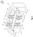
- Fig. 1 exemplary shows an arrangement of work spindles and working units according to an exemplary embodiment of the invention.
- a machine tool 100 includes a first work spindle 200a and a second work spindle 200b being arranged opposite to each other as well as a first working unit 201a (see figure 2 ) and a second working unit 201b (see figure 2 ).
- the first work spindle 200a depicted on the right side of Fig. 1 may be a counter spindle and the second work spindle 200b depicted on the left side of Fig. 1 may be a main spindle.
- the two work spindles 200a, 200b represent two independent work spindles, each provided to receive a workpiece to be machined or to be bent by one of the working units.
- the bold arrows near the depicted work spindles 200a, 200b and near the working units 201a, 201b indicate the movement direction of said elements so that said elements may be linearly moved throughout the entire machining area.
- the associated coordinate system is shown at the top of Fig. 1 , wherein the Z-axis is a horizontal axis preferably parallel to the spindle axis of the first work spindle.
- the first working tool 201a is disposed above the first spindle 200a and the second working tool is disposed below the first spindle 200a, as shown in e.g. figure 2a or 2b .
- the working units are mounted onto tool carrier slides 152.
- the machine tool 100 with the arrangement of spindles and working units depicted in Fig. 1 includes a machine frame 110 supporting four tool carrier assemblies 150a - 150d.
- the respective directions along which each tool carrier assembly 150a - 150d can be linearly moved are the X-, Z-axis and, optionally also the Y-axis, directions which are indicated by doubled arrows in said figure.
- at least one working unit, here the first working unit 201a is mounted at one of the tool carriers 150a -or150c which allow a rotation around a B-axis (not shown figure 1 ). This means that the respectively mounted working unit can be rotated about an Y-axis.
- the first working unit 201a is mounted onto the (first) tool carrier assembly 150a and more particularly onto the tool carrier support slide 152, which are arranged on an upper tool carrier support portion 113 of the machine frame 110.
- the second working unit 201b is mounted onto a tool carrier assembly 150b and more particularly onto the tool carrier support slide 152, which are arranged on a lower tool carrier support portion 114 of the machine frame 110, wherein preferably a third and a fourth tool carrier assemblies 150c, 150d are provided which are arranged on the lower and upper tool carrier support portions 113, 114 to oppose each other and in a proximity of the second work spindle 200b.
- the machine tool has a configuration with at least two spindles, however a presence of a second work spindle 200b is optional, since in the required operations for the invention, which include bending and machining of the workpiece, may also be realized by using only the first work spindle 200a depicted in Figure 1 . Nevertheless, in the following examples the machine tool 100 has two spindles and four working units in order to further increase the production efficiency for multi-operation manufacturing of workpieces. However, a various modification of the structure of the machine tool can be implemented: a plurality of spindles can be implemented into the machine tool and a singule or a plurality of working units can be installed.
- the depicted machine frame 110 includes the upper tool carrier support portion 113 and a lower tool carrier support portion 114, both of which horizontally extending between the two machine stand portions 111a and 111b.
- the upper side surface of the upper tool carrier support portion 113 of the machine frame 110 is arranged at an inclined slope, and the lower side surface of the lower tool carrier support portion 114 of the machine frame 110 is arranged at an overhanging inclined slope.
- the upper tool carrier support portion 113 of the machine frame 110 has horizontally extending guides 113a. Accordingly, for slidably supporting the tool carrier assemblies 150c, 150d on the lower side of the machine frame 110 in a machining area of the machine tool 100, the lower tool carrier support portion 114 of the machine frame 110 has horizontally extending guides 114a.
- each tool carrier assembly 150a - 150d includes a carrier support slide 151 which is configured to be slidably mounted to the guides 113a or 114a of the upper and lower tool carrier support portions 113 or 114 of the machine frame 110. Accordingly, when mounted on top of the upper tool carrier support portion 113 on the guides 113a, the carrier support slide 151 is configured to be moved horizontally on and along the guides 113a in the Z-axis direction. On the other hand, when mounted in a hanging state at the overhanging lower tool carrier support portion 114 at the guides 114a, the carrier support slide 151 is configured to be moved horizontally along the guides 113a in the Z-axis direction.
- a tool support slide 152 is slidably mounted to the carrier support slide 151.
- the tool carrier slide 152 is configured to be moved vertically on and along vertical guides arranged on a front face of the carrier support slide 151 in the X-axis direction.
- a horizontally arranged tool carrier quill (not depicted) extending from the front side of the tool carrier slide 152 in a Y-axis direction into the machining area of the machine tool 100 may be provided, to mount a working unit (tool/machining unit 201a etc.) at the front-side end portion of the tool carrier quill.
- the tool carrier quill can be mounted to the tool carrier slide 152 so as to controllably move horizontally in a Y-axis towards the front of the machine tool 100.
- the tool carrier quill may be configured to further include a rotatably driven B-axis so as to control a rotational movement of the working unit mounted to the tool carrier assembly 150a - 150d around the horizontally arranged longitudinal axis of the tool carrier quill, i.e. about a rotational axis extending in the Y-axis direction.
- the work spindles 200a, 200b and working units 201a, 201b may all be mounted to respective tool carrier assemblies 150a - 150d of the machine tool 100.
- the degree of freedom in terms of the linear and rotational movement of the work spindles 200a, 200b and working units 201a, 201b can thereby be further optimized.
- a more efficient way of manufacturing workpieces by applying bending and machining operations using the same machine tool can be achieved.
- the tool carrier slide 152 of the tool carrier assembly 150a can be moved vertically downward in the X-axis direction on the vertical guides of the carrier support slide 151, e.g., until it reaches its lowest position.
- the tool carrier slide 152 of the fourth tool carrier assembly 150d can be moved upward in the X-axis direction on the vertical guides of the carrier support slide 151, e.g., until it reaches its highest position. In this way, it is possible to arrange the main spindle and the counter spindle coaxially and opposite each other.
- the main and counter spindles may additionally be rotated about the respective B-axes of the first and fourth tool carrier assemblies 150a, 150d, to achieve the required position.
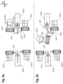
- a schematic perspective view in X-Z plane of a machine tool with the arrangement of spindles and working units mounted onto the machine tool as shown in Figure 1 is shown in figures 2a and 2b .
- the working units are positioned at the movable tool carrier slides 152 of Figure 1 .
- the first working spindle 200a is designed to receive the workpiece 203, which is for example a tubular workpiece.
- a preferrable positioning of the working units are as follows: the first working unit 201a is positioned vertically above the first work spindle 200a along X-axis and can be linearly moved in X-Z plane by the tool carrier assembly and, in addition, the first working unit 201a can be rotated around B-axis in the connection point between the first working unit and the tool carrier assembly as demonstrated in Figure 2a .
- the first working unit 201a is a tool turret.
- the tool turret has a turret body having at least one connecting spot for replaceably mounting a tool holder (or directly a tool) to the tool turret.
- the tool turret is designed as a disk turret which, to enable each tool to be moved into an operating position, can be turned in a controlled manner about a turret axis extending parallel to the workpiece spindle axis, at least in a lathe without a B-axis or in a lathe with a B-axis in the starting position of the tool turret.
- the turret head can be rotated by at least 100 degrees, more preferably 110 degrees around the turret axis.
- the other working units 201b to 201c are also such type of tool turrets so that they may be interchanged, as shown in figure 2a and 2b .
- the second working unit 201b is positioned vertically below the first work spindle 200a, wherein the second working unit 201b is linearly movable, at least, in the Z-direction and more preferably in the X-Z plane.
- the first and the second working units are used to bend the workpiece 203 received by the working spindle by a bending tool.
- the bending tool includes a pressure die 301, a bending die 302 and a clamping portion 303 as shown in Figure 2a which is used to bend the workpiece 203, wherein different parts of the bending tool are arranged/mounted on different units of the machine tool.
- the pressure die 301 is mounted on the first working unit 201a, preferably at a tool reception portion the first working unit 201a.
- the bending die 302 is mounted on the second working unit 201b, or preferably on a tool reception portion of the second working unit 201b.
- the first and second working units are tool turrets, which may hold a plurality of elements for machining the workpiece 203. Accordingly, a bending operation can be included directly in a sequence of machining steps of a manufacturing process on a machine tool, in particular a lathe.
- the clamping portion 303 which is designed to clamp and/or fix the workpiece 203 in addition to the spindle.
- the workpiece is clamped and/or fixed by the clamping portion during the bending operation.
- the clamping portion 303 of the bending tool can be fixed directly to the machine frame 110 or can be mounted on the second working unit 201b, for example in a tool receiving portion thereof (or connecting spot).
- one part of the clamping portion 303 e.g. upper clamping portion
- another part of the clamping portion 303 e.g. lower clamping portion
- the clamping portion 303 can fix the position of the workpiece 203.
- the clamping portion is located between the first work spindle 200a and the pressure die 301, the bending die 302.
- the workpiece 203 received by the first work spindle 200a is fixed by the clamping portion 303 before and in particular during the bending operation.
- the first working unit 201a is configured to generate a bending force or to apply torque via the bending die face of the pressure die which is in contact with the workpiece to therefore bend the fixed workpiece 203 held in the first work spindle 200a. Bending is achieved by rotating the first working unit 201a around the B-axis.
- the first working unit 201a can additionally be moved linearly at least along Z-axis or in X-Z plane for enhancing the bending operation at the time of rotating the first working unit around B-axis.
- the pressure die 301 is carried or mounted in a in a connecting spot (or tool receiving interface) of the disc of the tool turret 201a, wherein the tool turret is movable in order to advance the pressure die 301 into bending engagement with a length of the workpiece, in particular a metal tubing supported by the clamping portion 303 and received in the first working spindle 200a.
- the clamping portion has two parts which are arranged circumferentially of the clamped workpiece.
- the bending die 302 is carried in a connecting spot (or tool receiving interface) of the working unit 201b.
- Said bending die 302 preferably has a convexly curved, typically semi circularly shaped bending die face which cooperate with complementary die faces of the pressure die to define a channel of e.g. generally circular (or elliptical or rectangular) cross section having a diametric size closely matching the size of the workpiece (or tubular workpiece) being bent by the machine tool.
- the motion for bending the supported workpiece can be performed by the tool turret 201a in order to apply the necessary pressure onto the workpiece.
- the tool turret 201a may be controlled to move along the Z-axis direction and at the same time rotate around the B-axis in order to bend the end portion of the workpiece 203, as shown in figure 2b , downwardly, i.e. into the desired bending position.
- the bending die 302 may be static or can also be advancing along a line extending parallel to the Z-axis and pushes into the supported workpiece. This combination of bending die and pressure die cooperates to bend the workpiece through a selected angle, in accordance with the advancement stroke length of the pressure die and/or the movement of the bending die.
- the workpiece is pressed by the pressure die 301 of the first working unit 201a against the bending die 302, which works as a counter part for bending the workpiece 203 to a predetermined radius as demonstrated in Figure 2b .
- the further manufacturing operations can be performed on the workpiece 203.
- the workpiece can be further bended in e.g. a different plane by unfixing the workpiece 203 of the clamping portion 303, rotating the workpiece 203 by the first work spindle 200a, fixing the workpiece 203 with the clamping portion 303 and performing another bending operation.
- the bended part can also be machined by tools mounted at one of the working units.
- the machine tool 100 may further comprise a second work spindle 200b (e.g. the main spindle), which is shown on the left side of the Figures 2a and 2b with the workpiece 203, wherein third and fourth working units 201c and 201d are configured to machine the workpiece 203 received by the main spindle.
- the spindles can have fixed positions attached to the machine frame or in an alternative embodiment the spindles can be attached to the tool carrier slides.
- the third and fourth working units 201c and 201d are located vertically above and vertically below the second working spindle 200b similar to a position of the working units 201a and 201b to the first working spindle 200a. These additional working units can be implemented for machining the workpiece received by the second work spindle 200b before transporting the workpiece to the first work spindle 200a for further bending operations.
- Transport of the workpiece can be achieved, for example, by moving the main spindle together with the workpiece along the z-axis direction to the auxiliary spindle (first working spindle 200a) and inserting the workpiece into the opening of the auxiliary spindle such that the auxiliary spindle can clamp the workpiece and the main spindle can release the workpiece and move back to the initial position (which is shown in figure 2a ).
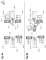
- FIGS 3a and 3b A further development is shown in Figures 3a and 3b .
- This development differs from the embodiment in figure 2a and 2b in view of the different bending tool.
- the bending tool according as shown in figures 3a and 3b does not require the clamping portion 303 since the clamping force of the auxiliary spindle (first work spindle 200a) is increased to achieve a tight clamping force and to fix the workpiece for the bending operation.
- the workpiece 203 is received by the first work spindle 200a, and the first work spindle 200a can be used to fix the workpiece instead of the clamping portion 303.
- the workpiece 203 can be fixed/clamped by a collet system of the work spindle, e.g., the first work spindle 200a in Figure 3a and 3b .
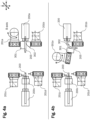
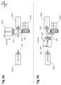
- FIG. 4a and 4b Another embodiment based on a modification of the developments in figures 2a and 2b or figures 3a and 3b is suggested in figure 4a and 4b .
- the machine tool is optimized to work in a swiss type configuration, wherein the workpiece is moved along the z-axis, wherein the workpiece-stock is held by a collet that is recessed behind a guide bush.
- a first workpiece can therefore be machined by the working unit 201c and/or 201d, while being clamped into the main spindle 200c.
- another workpiece can be bent by the first working unit 201a while being clamped into the auxiliary spindle 200a.
- said workpiece can be released and another machined workpiece can be received by the auxiliary spindle for the next bending process.
- a continuous process can be achieved where a workpiece is processed by machining operations when clamped into the main spindle, and after being moved to and clamped into the auxiliary spindle, bending of said workpiece can be performed so that it is possible to perform bending and machining of the workpiece with the same machine tool including autonomous changing the clamping of the workpiece. Moreover, while the bending operation for one workpiece is performed, another workpiece can already be machined.
- the first working unit 201a is a milling head and the pressure die 301 of the bending tool is mounted (or attached) to tool receiving section of the milling head.
- the workpiece 203 is thereby fixed by the collet system of the first work spindle 200a.
- the milling head is rotated around the B-axis and moved in the XZ plane. Accordingly, in particular on a lathe with milling units, the turret can be substituted by a fixed support.
- the bending tool can be implemented into the configuration of the machine tool 100.
- the bending tool thereby comprises the pressure die 301 and the bending die 302, wherein both the pressure die 301 and the bending die 302 have at least one guiding path for bending a workpiece, in particular a pipe or tubular workpiece, the bending die 302, in a more preferrable development, has at least two guiding paths with different radii for bending the same workpiece 203 under different angles, as shown in figure 6b (this bending die may be referred to as multi-shape bending die).
- the pressure die 301 can be received in a tool receiving portion of the tool turret 201a.
- the multi-shape bending die 302 can be mounted in a tool receiving portion of an adjacent tool turret.
- the bending die 302 is moved along the Y-axis direction, as shown in figure 6b , for example by moving the tool turret in which the bending die is mounted, accordingly.
- a preferrable bending process using the multi-shape bending die 302 mounted in the machine tool allows a bending process with two or more different bending shapes or radii (each having a respective bending die face, i.e. the bending die has a first bending die face and a second bending die face, each face having a different shape such as a different radius).
- a particular advantage can be achieved when the multi-shape bending die is used for bending a workpiece using the machine tool, such that, after a first bending operation (using the first bending die face) and when it is determined (automatically and therefore for example by using a movable probe of the machine tool) that the shape of the workpiece after the first bending process does not fulfil a predetermined criteria (such as a desired shape or radius) a second bending operation can be performed with the same bending die which is switched such that the second bending die face is used for the bending operation and contacting the workpiece at the time of the bending operation.
- the same bending tool can be configured to perform different bending operations so that even bending in different planes with different radii is possible because the spindle having the workpiece can be rotated after the first bending operation.
- the bending die has two separate and different bending surfaces (bending die faces having different radius R1 and R2 and different path lengths defined by the path-angles a1 and a2), which are spaced apart in the Y-direction.
- bending die faces Preferably one of the bending die faces can be used to correct a shape of a bent workpiece, bent by the other bending die face.
- a workpiece is shown which has been bent by using the machine tool, wherein the bending inclination is achieved in different planes.
- the bending inclination is achieved in different planes.
- a workpiece held in the work spindle 200a i.e. rotating the spindle
- a following bending step a bending inclination in a different plane can be achieved.
- a highly flexible and efficient manufacturing process can therefore be achieved.
- the flexibility can be even further enhanced, when in such a process also a multi-shape bending die with different shapes is used.
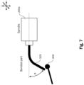
- the probe can be a probe configured to be touched by an object to be detected such as a workpiece, and a sensor sensing displacement of the probe and outputting a detection signal when the probe is displaced by the object to be touched can be provided.
- a bending inclination of the bent workpiece may be measured.
- the probe has a touch surface (touching part) to be touched by the object to be detected, and has a first shaft configured to swing in the touching direction of the object when the object touches the touch surface, and a second shaft connected to the first shaft and configured to be displaced in an axial direction thereof by swing of the first shaft.
- the sensor is configured to sense displacement of the first and/or second shaft and may output a detection signal. Therefore, measuring geometric tolerances using the machine tool and automatically compensating for spatial errors in the machining area can be achieved.
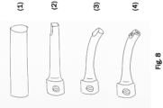
- step (1) the raw material is shown, which may be the initial shape of the workpiece, which preferably is a cylindrical and/or hollow workpiece. Said workpiece is clamped into the working spindle.
- machining of the workpiece clamped into one of the working spindles 200a or 200b can be performed.
- a diameter or edge of the workpiece is shaped using milling or turning operations of the machine tool, in particular using a tool or a tool turret or milling head.
- a step (3) it is possible in a step (3) to bend the workpiece in order to achieve a desired bended shape of the workpiece.
- the workpiece can remain clamped in the working spindle so that it is not necessary to re-clamp the workpiece after the machining step in order to perform the bending step.
- the workpiece can be clamped into the opposing working spindle.
- the workpiece can be machined after the bending step again.
- the bending step causes a shift of geometric relations of the e.g. surface elements and shape of the workpiece, it is sometimes necessary to perform final machining steps only on the fully bent workpiece.
- steps (2) to (4) may also be performed in a different order.
- a more efficient way of manufacturing workpieces by applying bending and machining operations using the same machine tool can be achieved.
Landscapes
- Engineering & Computer Science (AREA)
- Mechanical Engineering (AREA)
- Bending Of Plates, Rods, And Pipes (AREA)
- Turning (AREA)
Priority Applications (4)
| Application Number | Priority Date | Filing Date | Title |
|---|---|---|---|
| EP23171049.2A EP4458484A1 (de) | 2023-05-02 | 2023-05-02 | Verfahren zum biegen und bearbeiten von werkstücken an einer werkzeugmaschine sowie werkzeugmaschine zum bearbeiten und biegen von werkstücken |
| US18/646,950 US20240367210A1 (en) | 2023-05-02 | 2024-04-26 | Method for bending and machining workpieces on a machine tool, and machine tool for machining and bending workpieces |
| CN202410540251.2A CN118893114A (zh) | 2023-05-02 | 2024-04-30 | 在机床上折弯和加工工件的方法以及用于加工和折弯工件的机床 |
| JP2024073627A JP2024160976A (ja) | 2023-05-02 | 2024-04-30 | 工作機械上でワークピースに曲げ加工および機械加工を行うための方法、ならびにワークピースに機械加工および曲げ加工を行うための工作機械 |
Applications Claiming Priority (1)
| Application Number | Priority Date | Filing Date | Title |
|---|---|---|---|
| EP23171049.2A EP4458484A1 (de) | 2023-05-02 | 2023-05-02 | Verfahren zum biegen und bearbeiten von werkstücken an einer werkzeugmaschine sowie werkzeugmaschine zum bearbeiten und biegen von werkstücken |
Publications (1)
| Publication Number | Publication Date |
|---|---|
| EP4458484A1 true EP4458484A1 (de) | 2024-11-06 |
Family
ID=86328414
Family Applications (1)
| Application Number | Title | Priority Date | Filing Date |
|---|---|---|---|
| EP23171049.2A Pending EP4458484A1 (de) | 2023-05-02 | 2023-05-02 | Verfahren zum biegen und bearbeiten von werkstücken an einer werkzeugmaschine sowie werkzeugmaschine zum bearbeiten und biegen von werkstücken |
Country Status (4)
| Country | Link |
|---|---|
| US (1) | US20240367210A1 (de) |
| EP (1) | EP4458484A1 (de) |
| JP (1) | JP2024160976A (de) |
| CN (1) | CN118893114A (de) |
Families Citing this family (1)
| Publication number | Priority date | Publication date | Assignee | Title |
|---|---|---|---|---|
| EP3871834A1 (de) * | 2020-02-28 | 2021-09-01 | Gildemeister Italiana S.r.l. | Werkzeugmaschine, insbesondere drehmaschine mit hilfsspindel |
Citations (6)
| Publication number | Priority date | Publication date | Assignee | Title |
|---|---|---|---|---|
| JP2005161331A (ja) | 2003-11-28 | 2005-06-23 | Toyota Motor Corp | 曲げ加工装置と曲げ加工方法 |
| US20120016511A1 (en) * | 2009-04-08 | 2012-01-19 | Kabushiki Kaisha Opton | Bending device |
| DE102015208350B3 (de) * | 2015-05-06 | 2016-08-25 | Wafios Aktiengesellschaft | Verfahren zur Herstellung von Formteilen und Umformmaschine zur Durchführung des Verfahrens |
| JP2020032528A (ja) | 2018-08-29 | 2020-03-05 | ギルドメイスター イタリアーナ ソシエタ ペル アチオニ | 工作機械、特に旋盤 |
| WO2023004155A2 (en) * | 2021-07-22 | 2023-01-26 | Scofast Llc | System and method to perform dissimilar operations in a single machine |
| US20230078509A1 (en) * | 2020-02-28 | 2023-03-16 | Gildemeister Italiana S.R.L. | Machine tool, in particular lathe with auxiliary spindle |
-
2023
- 2023-05-02 EP EP23171049.2A patent/EP4458484A1/de active Pending
-
2024
- 2024-04-26 US US18/646,950 patent/US20240367210A1/en active Pending
- 2024-04-30 JP JP2024073627A patent/JP2024160976A/ja active Pending
- 2024-04-30 CN CN202410540251.2A patent/CN118893114A/zh active Pending
Patent Citations (6)
| Publication number | Priority date | Publication date | Assignee | Title |
|---|---|---|---|---|
| JP2005161331A (ja) | 2003-11-28 | 2005-06-23 | Toyota Motor Corp | 曲げ加工装置と曲げ加工方法 |
| US20120016511A1 (en) * | 2009-04-08 | 2012-01-19 | Kabushiki Kaisha Opton | Bending device |
| DE102015208350B3 (de) * | 2015-05-06 | 2016-08-25 | Wafios Aktiengesellschaft | Verfahren zur Herstellung von Formteilen und Umformmaschine zur Durchführung des Verfahrens |
| JP2020032528A (ja) | 2018-08-29 | 2020-03-05 | ギルドメイスター イタリアーナ ソシエタ ペル アチオニ | 工作機械、特に旋盤 |
| US20230078509A1 (en) * | 2020-02-28 | 2023-03-16 | Gildemeister Italiana S.R.L. | Machine tool, in particular lathe with auxiliary spindle |
| WO2023004155A2 (en) * | 2021-07-22 | 2023-01-26 | Scofast Llc | System and method to perform dissimilar operations in a single machine |
Also Published As
| Publication number | Publication date |
|---|---|
| CN118893114A (zh) | 2024-11-05 |
| US20240367210A1 (en) | 2024-11-07 |
| JP2024160976A (ja) | 2024-11-15 |
Similar Documents
| Publication | Publication Date | Title |
|---|---|---|
| US6874213B2 (en) | Machine tool and method for machining a rod-shaped workpiece | |
| EP2505304B1 (de) | Vorrichtung zum Auswechseln eines Werkzeugs und Arbeitsmaschine damit | |
| US8464618B2 (en) | Numerically controlled lathe with guide bush, and method of processing workpiece by using the numerically controlled lathe | |
| EP1485231B1 (de) | Werkzeugmaschine | |
| US6836941B2 (en) | Machine tool for machining a rod-shaped workpiece | |
| US8573100B2 (en) | Loading magazine with moveable channel system for loading and unloading automatic lathes | |
| US20140298961A1 (en) | Machine tool | |
| JP2005125482A (ja) | 旋盤 | |
| JP7789005B2 (ja) | 工作機械、特に補助スピンドルを備えた旋盤 | |
| JP2008540145A (ja) | 別々のキャリッジに2つのクランプ点を備えた工作機械 | |
| US20240367210A1 (en) | Method for bending and machining workpieces on a machine tool, and machine tool for machining and bending workpieces | |
| JP3892482B2 (ja) | 多スピンドル回転機械 | |
| JP4271402B2 (ja) | 細物ワーク加工用の2主軸対向旋盤 | |
| KR100454184B1 (ko) | 선회가능한 스핀들 유니트를 갖춘 nc 공작기계 | |
| US20070084319A1 (en) | Lathe | |
| JP3979722B2 (ja) | 旋盤用補助ガイド装置及び補助ガイド装置を備えた自動旋盤 | |
| JP2004261935A (ja) | ワークの振れ止め装置を備えた旋盤 | |
| JP4496134B2 (ja) | 旋盤 | |
| EP4431230A1 (de) | Werkzeugmaschine, insbesondere drehmaschine, und verfahren zum bearbeiten von werkstücken mit einer werkzeugmaschine | |
| CN211805570U (zh) | 一种曲线进给机构 | |
| CN111347350B (zh) | 一种曲线进给机构 | |
| KR20200106658A (ko) | 보링 바의 툴 교환 장치 및 이를 이용한 보링 바의 툴 교환 방법 | |
| CN120857995A (zh) | 用于在多轴车床上加工工件的装置和方法 | |
| CN214642235U (zh) | 型材多工位数控加工中心 | |
| CN119057484A (zh) | 一种车铣复合加工方法 |
Legal Events
| Date | Code | Title | Description |
|---|---|---|---|
| PUAI | Public reference made under article 153(3) epc to a published international application that has entered the european phase |
Free format text: ORIGINAL CODE: 0009012 |
|
| STAA | Information on the status of an ep patent application or granted ep patent |
Free format text: STATUS: THE APPLICATION HAS BEEN PUBLISHED |
|
| AK | Designated contracting states |
Kind code of ref document: A1 Designated state(s): AL AT BE BG CH CY CZ DE DK EE ES FI FR GB GR HR HU IE IS IT LI LT LU LV MC ME MK MT NL NO PL PT RO RS SE SI SK SM TR |
|
| STAA | Information on the status of an ep patent application or granted ep patent |
Free format text: STATUS: REQUEST FOR EXAMINATION WAS MADE |
|
| 17P | Request for examination filed |
Effective date: 20250411 |