EP4458391A2 - System und verfahren zur steuerung der leistung eines pneumatisch abgedichteten trokars - Google Patents
System und verfahren zur steuerung der leistung eines pneumatisch abgedichteten trokars Download PDFInfo
- Publication number
- EP4458391A2 EP4458391A2 EP24194382.8A EP24194382A EP4458391A2 EP 4458391 A2 EP4458391 A2 EP 4458391A2 EP 24194382 A EP24194382 A EP 24194382A EP 4458391 A2 EP4458391 A2 EP 4458391A2
- Authority
- EP
- European Patent Office
- Prior art keywords
- pump
- controller
- motor
- positive pressure
- sealed trocar
- Prior art date
- Legal status (The legal status is an assumption and is not a legal conclusion. Google has not performed a legal analysis and makes no representation as to the accuracy of the status listed.)
- Pending
Links
Images


Classifications
-
- A—HUMAN NECESSITIES
- A61—MEDICAL OR VETERINARY SCIENCE; HYGIENE
- A61B—DIAGNOSIS; SURGERY; IDENTIFICATION
- A61B17/00—Surgical instruments, devices or methods
- A61B17/34—Trocars; Puncturing needles
- A61B17/3417—Details of tips or shafts, e.g. grooves, expandable, bendable; Multiple coaxial sliding cannulas, e.g. for dilating
- A61B17/3421—Cannulas
- A61B17/3423—Access ports, e.g. toroid shape introducers for instruments or hands
-
- A—HUMAN NECESSITIES
- A61—MEDICAL OR VETERINARY SCIENCE; HYGIENE
- A61B—DIAGNOSIS; SURGERY; IDENTIFICATION
- A61B17/00—Surgical instruments, devices or methods
- A61B17/34—Trocars; Puncturing needles
- A61B17/3474—Insufflating needles, e.g. Veress needles
-
- A—HUMAN NECESSITIES
- A61—MEDICAL OR VETERINARY SCIENCE; HYGIENE
- A61M—DEVICES FOR INTRODUCING MEDIA INTO, OR ONTO, THE BODY; DEVICES FOR TRANSDUCING BODY MEDIA OR FOR TAKING MEDIA FROM THE BODY; DEVICES FOR PRODUCING OR ENDING SLEEP OR STUPOR
- A61M13/00—Insufflators for therapeutic or disinfectant purposes, i.e. devices for blowing a gas, powder or vapour into the body
- A61M13/003—Blowing gases other than for carrying powders, e.g. for inflating, dilating or rinsing
-
- A—HUMAN NECESSITIES
- A61—MEDICAL OR VETERINARY SCIENCE; HYGIENE
- A61M—DEVICES FOR INTRODUCING MEDIA INTO, OR ONTO, THE BODY; DEVICES FOR TRANSDUCING BODY MEDIA OR FOR TAKING MEDIA FROM THE BODY; DEVICES FOR PRODUCING OR ENDING SLEEP OR STUPOR
- A61M13/00—Insufflators for therapeutic or disinfectant purposes, i.e. devices for blowing a gas, powder or vapour into the body
- A61M13/003—Blowing gases other than for carrying powders, e.g. for inflating, dilating or rinsing
- A61M13/006—Blowing gases other than for carrying powders, e.g. for inflating, dilating or rinsing with gas recirculation
-
- A—HUMAN NECESSITIES
- A61—MEDICAL OR VETERINARY SCIENCE; HYGIENE
- A61B—DIAGNOSIS; SURGERY; IDENTIFICATION
- A61B17/00—Surgical instruments, devices or methods
- A61B2017/00017—Electrical control of surgical instruments
- A61B2017/00137—Details of operation mode
- A61B2017/00154—Details of operation mode pulsed
- A61B2017/00172—Pulse trains, bursts, intermittent continuous operation
-
- A—HUMAN NECESSITIES
- A61—MEDICAL OR VETERINARY SCIENCE; HYGIENE
- A61B—DIAGNOSIS; SURGERY; IDENTIFICATION
- A61B17/00—Surgical instruments, devices or methods
- A61B2017/00535—Surgical instruments, devices or methods pneumatically or hydraulically operated
- A61B2017/00544—Surgical instruments, devices or methods pneumatically or hydraulically operated pneumatically
-
- A—HUMAN NECESSITIES
- A61—MEDICAL OR VETERINARY SCIENCE; HYGIENE
- A61B—DIAGNOSIS; SURGERY; IDENTIFICATION
- A61B17/00—Surgical instruments, devices or methods
- A61B2017/00681—Aspects not otherwise provided for
- A61B2017/00734—Aspects not otherwise provided for battery operated
-
- A—HUMAN NECESSITIES
- A61—MEDICAL OR VETERINARY SCIENCE; HYGIENE
- A61B—DIAGNOSIS; SURGERY; IDENTIFICATION
- A61B17/00—Surgical instruments, devices or methods
- A61B17/34—Trocars; Puncturing needles
- A61B17/3417—Details of tips or shafts, e.g. grooves, expandable, bendable; Multiple coaxial sliding cannulas, e.g. for dilating
- A61B2017/3419—Sealing means between cannula and body
-
- A—HUMAN NECESSITIES
- A61—MEDICAL OR VETERINARY SCIENCE; HYGIENE
- A61M—DEVICES FOR INTRODUCING MEDIA INTO, OR ONTO, THE BODY; DEVICES FOR TRANSDUCING BODY MEDIA OR FOR TAKING MEDIA FROM THE BODY; DEVICES FOR PRODUCING OR ENDING SLEEP OR STUPOR
- A61M2205/00—General characteristics of the apparatus
- A61M2205/33—Controlling, regulating or measuring
- A61M2205/3331—Pressure; Flow
- A61M2205/3334—Measuring or controlling the flow rate
-
- A—HUMAN NECESSITIES
- A61—MEDICAL OR VETERINARY SCIENCE; HYGIENE
- A61M—DEVICES FOR INTRODUCING MEDIA INTO, OR ONTO, THE BODY; DEVICES FOR TRANSDUCING BODY MEDIA OR FOR TAKING MEDIA FROM THE BODY; DEVICES FOR PRODUCING OR ENDING SLEEP OR STUPOR
- A61M2205/00—General characteristics of the apparatus
- A61M2205/33—Controlling, regulating or measuring
- A61M2205/3331—Pressure; Flow
- A61M2205/3344—Measuring or controlling pressure at the body treatment site
-
- A—HUMAN NECESSITIES
- A61—MEDICAL OR VETERINARY SCIENCE; HYGIENE
- A61M—DEVICES FOR INTRODUCING MEDIA INTO, OR ONTO, THE BODY; DEVICES FOR TRANSDUCING BODY MEDIA OR FOR TAKING MEDIA FROM THE BODY; DEVICES FOR PRODUCING OR ENDING SLEEP OR STUPOR
- A61M2205/00—General characteristics of the apparatus
- A61M2205/50—General characteristics of the apparatus with microprocessors or computers
Definitions
- the subject disclosure relates to gas delivery systems for use with surgical access devices, and more particularly, to a system and method for controlling the performance of a pneumatically sealed trocar used in endoscopic or laparoscopic surgical procedures.
- Pneumatically sealed trocars such as those disclosed for example in commonly assigned U.S. Patent No. 7,854,724 and U.S. Patent No. 8,795,223 can be operated via an electro-mechanical control system.
- control systems are disclosed for example in commonly assigned U.S. Patent No. 8,715,219 , U.S. Patent No. 8,961,451 , and U.S. Patent No. 9,295,490 .
- These systems function to create and maintain a pneumatic or gaseous seal within the trocar that creates a defined pressure gradient for minimally-invasive laparoscopic or endoscopic surgeries.
- the pneumatic power required to seal a pneumatically-sealed trocar is also dependent on the magnitude of the pressure gradient maintained by the pneumatic seal. For example, a surgical team might choose to insufflate a patient to 15 mmHg, requiring the pneumatic seal in a pneumatically-sealed trocar to maintain a gradient between 15 mmHg and ambient pressure (0 mmHg).
- the power required to maintain this seal is larger than the power required to maintain a gradient between 10 mmHg and 0 mmHg, for example.
- an electro-mechanical control system operating a pneumatically sealed trocar should be able to modulate power supplied to that trocar in real-time to respond to those disturbances and maintain the seal and pressure gradient as specified.
- the control system disclosed in U.S. Patent No. 8,715,219 includes an electro-mechanical control valve that modulates pneumatic power supplied to the trocar.
- a pump typically driven by AC or alternating current
- the pneumatic power that is supplied to the pneumatically-sealed trocar is modulated by an embedded control system that adjusts the electro-mechanical valve.
- the AC driven pump in that system embodiment supplies a constant power output, and the position of the electro-mechanical valve controls the percentage of that power that reaches the pneumatically-sealed trocar and the percentage that is recycled back to the vacuum intake of the pump.
- the subject invention is directed to a new and useful system for controlling the performance range of a pneumatically sealed trocar during an endoscopic or laparoscopic surgical procedure.
- the system includes a controller for delivering variable DC voltage to a DC motor, a DC motor operatively connected to the controller for driving a pump operatively connected to a pneumatically sealed trocar, a pump driven by the DC motor for circulating pressurized gas through the pneumatically sealed trocar, and a sensor for sensing pressure and/or flow parameters between the pump and the trocar to provide a feedback control signal to the controller so that the controller can vary the voltage delivered to the DC motor to affect the output pressure and flow of the pump.
- the system further includes an AC input voltage source and an AC-DC converter for supplying DC voltage to the controller.
- the system includes a controller for delivering variable DC voltage to at least one DC motor, at least one DC motor operatively connected to the controller for driving at least one pump operatively connected to a pneumatically sealed trocar, at least one pump driven by the DC motor for circulating pressurized gas through the pneumatically sealed trocar, and at least one sensor for sensing pressure and/or flow parameters between the at least one pump and the pneumatically sealed trocar to provide at least one feedback control signal to the controller so that the controller can vary the voltage delivered to the at least one DC motor to affect the output pressure and flow of the at least one pump during an endoscopic or laparoscopic surgical procedure.
- the at least one sensor includes a first sensor for sensing positive pressure and flow parameters between the at least one pump and an inlet port of the pneumatically sealed trocar to provide a first feedback control signal to the controller and a second sensor for sensing negative pressure and/or flow parameters between the at least one pump and an outlet port of the pneumatically sealed trocar to provide a second feedback control signal to the controller.
- the at least one DC motor includes at least a first DC motor for driving at least one positive pressure pump connected to the pneumatically sealed trocar and at least a second DC motor for driving at least one negative pressure pump connected to the pneumatically sealed trocar.
- the at least one sensor includes a first sensor for sensing positive pressure and/or flow parameters between the positive pressure pump and an inlet port of the pneumatically sealed trocar to provide a first feedback control signal to the controller and a second sensor for sensing negative pressure and/or flow parameters between the negative pressure pump and the outlet port of the pneumatically sealed trocar to provide a second feedback control signal to the controller.
- the at least one pump includes at least first and second pumps that are arranged in parallel and are driven by the at least one DC motor. It is envisioned that controller could be adapted and configured to control the first and second pumps at the same or different output levels to meet different system requirements.
- the at least one DC motor and the AC-to-DC converter are replaced by at least one brushless stepper motor, at least one motor driver, and a pulse generator, which function together as a type of DC controller, though technically the performance output is not controlled solely by modulating supplied DC voltage.
- the mechanical and pneumatic outputs of the components in this embodiment are controlled precisely by electrical signal modulation, as in the DC motor embodiments described previously.
- electrical pulses controlled from a pulse generator are varied and supplied to a motor driver that drives a brushless stepper motor.
- electrical pulses of varying strength and length may be used to control precise rotation of the stepper motor by movements of a magnetic field generated by magnets in the motor. This will allow for precision control of motor behavior as well as accurate and repeatable start/stop behavior.
- the subject invention is also directed to a new and unique method for controlling the performance range of a pneumatically sealed trocar.
- the method includes the steps of providing a pump for circulating pressurized gas through a pneumatically sealed trocar, driving the pump by way of a DC motor, and controlling the voltage delivered to the DC motor based upon sensed parameters of gas flowing between the pump and the pneumatically sealed trocar to affect the output pressure and flow of the pump during a laparoscopic surgical procedure.
- the method also preferably includes the step of sensing pressure and/or flow parameters of the gas flowing between the pump and the pneumatically sealed trocar.
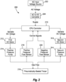
- Fig. 1 a system for controlling the performance range of a pneumatically sealed trocar during an endoscopic or laparoscopic surgical procedure, which is constructed in accordance with a preferred embodiment of the subject invention and designated generally by reference numeral 100.
- the system 100 includes a controller 110 for delivering variable DC voltage to a DC motor 112.
- the DC motor 112 is operatively connected to the controller 110 for driving a positive pressure pump 114 that is operatively connected to a pneumatically sealed trocar 116.
- the pump 114 is driven by the DC motor 112 to circulate pressurized gas through the pneumatically sealed trocar 116.
- a first sensor 118 is provided for sensing positive pressure and/or flow parameters between the pump 114 and an inlet port of the pneumatically sealed trocar 116 to provide a first feedback control signal to the controller 110.
- a second sensor 120 is provided for sensing negative pressure and/or flow parameters between the pump 114 and an outlet port of the pneumatically sealed trocar 116 to provide a second feedback control signal to the controller 110.
- the first and second feedback control signals enable the controller 110 to vary the voltage delivered to the DC motor 112 to affect the output pressure and/or flow of the pump 114.
- the system 100 further includes an AC input voltage source 122 and an AC-DC converter 124 for supplying DC voltage to the controller 110.
- System 200 differs from system 100 in that it includes a first DC motor 212 for driving a positive pressure pump 214 connected to a pneumatically sealed trocar 216 and a second DC motor 312 for driving a negative pressure pump 314 connected to the pneumatically sealed trocar 216.
- the system 200 further includes a first sensor 218 for sensing positive pressure and/or flow parameters between the positive pressure pump 214 and an inlet port of the pneumatically sealed trocar 216 to provide a first feedback control signal to a controller 210 and a second sensor 220 for sensing negative pressure and/or return flow parameters between the negative pressure pump 314 and the outlet port of the pneumatically sealed trocar 216 to provide a second feedback control signal to the controller 210.
- the system 200 further includes an AC input voltage source 222 and an AC-DC converter 224 for supplying DC voltage to the controller 210.
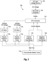
- the system 100 includes two positive pressure pumps 114a and 114b, driven by respective DC motors 112a and 112b. These pumps and motors are arranged or otherwise stacked in parallel to increase the pneumatic power capabilities of the system 100, and provide additional control options to improve system efficiency. Moreover, by placing two DC driven pumps in parallel, twice the pneumatic output can be supplied. In this instance, the controller or CPU 110 controls the performance output of one or both of the pumps, depending upon the system demands.
- the first pump 114a could always be controlled to 100% of its output (i.e., 50 L/min), while the output of the second pump 114b could be variably controlled to between 0-50 L/min, in order to achieve the system requirement.
- both DC driven pumps 114a, 114b could be controlled to the same output level.
- both pumps 114a, 114b would be controlled to a 40 L/min output.
- the two pumps 114a, 114b could be controlled to different levels.
- pump 114a could be controlled to 45 L/min and pump 114b could be controlled to 35 L/min.
- a larger DC power supply would be required (e.g., 24V to supply two 12V motors) and the CPU 110 will be responsible for dividing and regulating the voltage supplied between the two motors 112a, 112b as specified, which in turn, will control the output of their respective pumps 114a, 114b. While this embodiment of Fig. 3 has been shown and described as having two DC driven positive pressure pumps stacked together in a parallel relationship, it is envisioned that more than two pumps or similar or varying capacity can be arranged in this manner to further increase and diversify the operational capabilities of the control system disclosed herein.
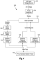
- FIG. 4 there is illustrated another version of the control system 100 shown in Fig. 1 .
- the DC motor 112 and the AC-to-DC converter 124 shown in Fig. 1 are replaced by a brushless stepper motor 130, a motor driver 132, and a pulse generator 134.
- a brushless stepper motor 130 a motor driver 132
- a pulse generator 134 a pulse generator 134.
- Those skilled in the art might classify this embodiment as a type of DC controller, though technically the performance output is not controlled solely by modulating supplied DC voltage. Nevertheless, those skilled in the art will appreciate the similarities of this embodiment of the invention to other types of DC-controlled systems.
- the mechanical and pneumatic outputs of the components in this embodiment are controlled precisely by electrical signal modulation, as in the DC motor embodiments described previously.
- electrical pulses controlled from pulse generator 134 are varied and supplied to motor driver 132 that drives the brushless stepper motor 130. More particularly, electrical pulses of varying strength and length are used to control precise rotation of the stepper motor 130 by precise movements of a magnetic field generated by magnets in the motor. This allows for precision control of motor behavior as well as accurate and repeatable start/stop behavior.
- gear-like geometry of a stepper motor also enables a control system that verifies the number of "steps" of the gear as part of its embedded controls, which may allow for simpler design of the feedback loop to control pneumatic performance of the system by alleviating the need for at least one separate sensor (such as sensor 118 or 120).
- Fig. 4 has been shown and described as having one motor driver 132, one stepper motor 130 and one positive pressure pump 114, it is envisioned and well within the subject disclosure, that groupings of these three components (132, 130, 114) can be arranged in a parallel relationship as shown for example in Fig. 5 , to further increase and diversify the operational capabilities of the control system 100 disclosed herein. More particularly, as shown in Fig. 5 , the controller 110 can be configured to deliver variable pulse signals supplied by pulse generator 134 to a first grouping of components including motor driver 132a, stepper motor 130a and positive pressure pump 114a, as well as a second parallel grouping of components including motor driver 132b, stepper motor 130b and positive pressure pump 114b. It is envisioned that controller 110 would be configures to deliver the same or different strength or duration variable pulses to the parallel sets of components to meet system requirements.
- the required components may include, but are not limited to, a power supply converter or battery, a potentiometer (which varies circuit resistance to control voltage supplied to the DC component), a computer board (e.g., PC or the like), a permanent magnet motor, and others.
- the power supply converter or battery is used to supply the DC component with direct current (DC) rather than supplying alternating current (AC), which is supplied normally by power outlets and grids. Controlling the voltage supplied to the DC component will vary its performance output. For example, a 12V DC motor will output more power when supplied with 10V than it would when supplied with 6V. This control is frequently achieved via a loop controller in which a sensor measuring performance output (or some related metric) communicates with the computer board, which is programmed with a response. The computer board will trigger a change to the variable power supplied to the motor when the data from the sensor requires such change.
- DC direct current
- AC alternating current
- the method and apparatus of the subject invention modulates pneumatic power supplied to a pneumatically-sealed trocar in real-time via control of the pneumatic output of a DC driven pump.
- the control loop is designed around three main components: a CPU control board 110, a motor 112 that drives the pump 114, and a sensor 118.
- the system 100 consists of a transformer 124 that converts the AC current from the wall (outlet supply) to DC.
- the available power supply must meet or exceed the rating of the powered component (for example, DC power supply must be 12V to fully power a 12V motor).
- the CPU modulates how much voltage is supplied to the motor 112.
- Varying the voltage to the motor 112 will directly affect the pressure and flow output of the pump 114, which is recorded by sensor 118 that loops back to the CPU 110, informing the CPU of the system performance and guiding how to respond to continue control and modulation of the system 100 as required.
- the CPU 110 could modulate voltage supply to the motor 112 to vary and control vacuum pressure and gas flow using data from the negative pressure sensor 120.
- the CPU 110 could control a component like a potentiometer to modulate DC voltage supplied to the motor 112.
- potentiometers can add an additional component to the design and waste heat and energy from efficiency loss.
- a preferred embodiment could use pulse width modulation (PWM) to control voltage supply to the motor 112.
- PWM pulse width modulation
- This control method modulates pulses of the same magnitude voltage over variable time periods to produce an "effective" level of voltage supply. For example, PWM control of a 12V power supply would control longer duration pulses to create an "average" supply of 10V, whereas PWM control of that same 12V power supply would control shorter duration pulses to create an "average” supply of 4V.
- These pulses are modulated by timed control of transistors which can be turned on and off by the CPU 110.
- An alternate embodiment could independently control pressure and vacuum supplied to a pneumatically-sealed trocar via two independent DC pumps, as shown in Fig. 2 .
- This embodiment involves controlling one pump 214 to provide positive pressure and flow to the pneumatically-sealed trocar 216 and a separate pump 314 to provide a balancing negative pressure and return flow away from the trocar 216.
- This embodiment would allow for separate, real-time, independent control over the pressure flow and return/vacuum flow which could allow for a new paradigm of granular performance control.
- both pumps would be open to ambient and their performance would not be affected or limited by a single, closed-loop pneumatic circuit.
- the CPU 210 could call for a 0.1 L/min increase to the pressure pump 214 or a 0.1 L/min decrease to the suction pump 314 to balance performance, whereas previously it was impossible to create an imbalance between those two flow rates.
- This embodiment would require the pressure pump 214 to be open to ambient for its intake, and the vacuum/suction pump 314 to be open to ambient for exhaust. It is envisioned that the open intake to the pressure pump 214 and the open exhaust from the vacuum pump 314 would be filtered through a suitable filtration device or element.
- a DC-based control system is more energy efficient than an AC-based system.
- An AC pump needs to be oversized in order to fully encompass the operating range of the electro-mechanical control system. The nature of AC components is that they are always fully “on”, meaning that full power is required whenever the device is run.
- the pump(s) need only be powered to the exact level that is required. For example, if a system has an operating range up to 100 L/min, but a use scenario only requires an output of 20 L/min, the AC-based embodiment requires the single AC pump to be outputting 100 L/min (with 80 L/min diverted away), while the DC-based embodiment could power the DC pump only to a level that outputs 20 L/min. Not only is this arrangement more energy efficient, it reduces heat and sound generated by the moving mechanical components. As a result, it may be possible to reduce or eliminate insulating components in the design.
- a DC pump enables a single, global design as the power transformer merely needs to transform input voltage to 12 V to power the motor. This gives advantages in inventory control and economies of scale when manufacturing, which will lower the cost of goods. It can also eliminate the need for developing, qualifying, and documenting multiple versions of each device for different power grids.
Landscapes
- Health & Medical Sciences (AREA)
- Life Sciences & Earth Sciences (AREA)
- Surgery (AREA)
- General Health & Medical Sciences (AREA)
- Veterinary Medicine (AREA)
- Engineering & Computer Science (AREA)
- Biomedical Technology (AREA)
- Animal Behavior & Ethology (AREA)
- Heart & Thoracic Surgery (AREA)
- Public Health (AREA)
- Pathology (AREA)
- Nuclear Medicine, Radiotherapy & Molecular Imaging (AREA)
- Medical Informatics (AREA)
- Molecular Biology (AREA)
- Anesthesiology (AREA)
- Hematology (AREA)
- Surgical Instruments (AREA)
- External Artificial Organs (AREA)
Applications Claiming Priority (3)
| Application Number | Priority Date | Filing Date | Title |
|---|---|---|---|
| US15/817,897 US10702306B2 (en) | 2017-11-20 | 2017-11-20 | System and method for controlling the performance of a pneumatically sealed trocar |
| PCT/US2018/056704 WO2019099151A1 (en) | 2017-11-20 | 2018-10-19 | System and method for controlling performance of a pneumatically sealed trocar |
| EP18877595.1A EP3713506B1 (de) | 2017-11-20 | 2018-10-19 | System zur steuerung der leistung eines pneumatisch abgedichteten trokars |
Related Parent Applications (2)
| Application Number | Title | Priority Date | Filing Date |
|---|---|---|---|
| EP18877595.1A Division EP3713506B1 (de) | 2017-11-20 | 2018-10-19 | System zur steuerung der leistung eines pneumatisch abgedichteten trokars |
| EP18877595.1A Division-Into EP3713506B1 (de) | 2017-11-20 | 2018-10-19 | System zur steuerung der leistung eines pneumatisch abgedichteten trokars |
Publications (2)
| Publication Number | Publication Date |
|---|---|
| EP4458391A2 true EP4458391A2 (de) | 2024-11-06 |
| EP4458391A3 EP4458391A3 (de) | 2025-01-08 |
Family
ID=66534776
Family Applications (2)
| Application Number | Title | Priority Date | Filing Date |
|---|---|---|---|
| EP18877595.1A Active EP3713506B1 (de) | 2017-11-20 | 2018-10-19 | System zur steuerung der leistung eines pneumatisch abgedichteten trokars |
| EP24194382.8A Pending EP4458391A3 (de) | 2017-11-20 | 2018-10-19 | System und verfahren zur steuerung der leistung eines pneumatisch abgedichteten trokars |
Family Applications Before (1)
| Application Number | Title | Priority Date | Filing Date |
|---|---|---|---|
| EP18877595.1A Active EP3713506B1 (de) | 2017-11-20 | 2018-10-19 | System zur steuerung der leistung eines pneumatisch abgedichteten trokars |
Country Status (9)
| Country | Link |
|---|---|
| US (2) | US10702306B2 (de) |
| EP (2) | EP3713506B1 (de) |
| JP (2) | JP7039696B2 (de) |
| KR (2) | KR102737879B1 (de) |
| CN (1) | CN111655180A (de) |
| AU (2) | AU2018369033B2 (de) |
| CA (2) | CA3082531C (de) |
| ES (1) | ES2996107T3 (de) |
| WO (1) | WO2019099151A1 (de) |
Families Citing this family (9)
| Publication number | Priority date | Publication date | Assignee | Title |
|---|---|---|---|---|
| JP6076469B2 (ja) * | 2012-05-09 | 2017-02-08 | イーオン サージカル リミテッド | 腹腔鏡ポート |
| US10695511B2 (en) * | 2017-09-07 | 2020-06-30 | Conmed Corporation | Method for calibrating performance range of a pneumatically sealed trocar |
| US12076479B2 (en) | 2021-01-22 | 2024-09-03 | Conmed Corporation | Low pressure insufflation manifold assembly for surgical gas delivery system |
| US12403271B2 (en) | 2021-01-22 | 2025-09-02 | Conmed Corporation | Vane compressor for surgical gas delivery system with gas sealed insufflation and recirculation |
| US12070546B2 (en) | 2021-01-22 | 2024-08-27 | Conmed Corporation | Gas heater for surgical gas delivery system with gas sealed insufflation and recirculation |
| US12053572B2 (en) | 2021-01-22 | 2024-08-06 | Conmed Corporation | Surgical gas delivery system and method for gas sealed insufflation and recirculation using proportional valves |
| US11850354B2 (en) | 2021-01-22 | 2023-12-26 | Conmed Corporation | Gaseous sealing manifold assembly for surgical gas delivery system |
| US12397123B2 (en) | 2021-01-22 | 2025-08-26 | Conmed Corporation | Surgical gas delivery system and method for gas sealed insufflation and recirculation with UVC sterilization |
| WO2025010187A1 (en) | 2023-07-05 | 2025-01-09 | Conmed Corporation | Manifold assembly for multi-modal surgical gas delivery system |
Citations (4)
| Publication number | Priority date | Publication date | Assignee | Title |
|---|---|---|---|---|
| US7854724B2 (en) | 2003-04-08 | 2010-12-21 | Surgiquest, Inc. | Trocar assembly with pneumatic sealing |
| US8715219B2 (en) | 2008-10-10 | 2014-05-06 | Surgiquest, Inc. | System and method for improved gas recirculation in surgical trocars with pneumatic sealing |
| US8795223B2 (en) | 2011-03-08 | 2014-08-05 | Surgiquest, Inc. | Trocar assembly with pneumatic sealing |
| US8961451B2 (en) | 2006-12-18 | 2015-02-24 | Surgiquest, Inc. | System for surgical insufflation and gas recirculation |
Family Cites Families (27)
| Publication number | Priority date | Publication date | Assignee | Title |
|---|---|---|---|---|
| US4770168A (en) * | 1985-12-16 | 1988-09-13 | Tibor Rusz | Electrically controllable anesthesia vaporizer |
| DE3933856A1 (de) * | 1989-10-07 | 1991-04-18 | Wiest Peter P | Vorrichtung zum spuelen und absaugen von koerperhoehlen |
| EP0692265B1 (de) | 1991-08-21 | 2000-05-24 | Smith & Nephew, Inc. | Flüssigkeitsbehandlungssystem |
| US5242404A (en) * | 1992-02-12 | 1993-09-07 | American Cyanamid Company | Aspiration control system |
| JPH05337127A (ja) * | 1992-06-04 | 1993-12-21 | Olympus Optical Co Ltd | トラカール刺入装置 |
| US5403277A (en) | 1993-01-12 | 1995-04-04 | Minnesota Mining And Manufacturing Company | Irrigation system with tubing cassette |
| US5586974A (en) * | 1995-04-25 | 1996-12-24 | Olympus America, Inc. | Continuously adjustable high flow insufflator valve |
| US5830180A (en) | 1996-07-17 | 1998-11-03 | Aquarius Medical Corporation | Fluid management system for arthroscopic surgery |
| US6695823B1 (en) * | 1999-04-09 | 2004-02-24 | Kci Licensing, Inc. | Wound therapy device |
| WO2000061206A1 (en) | 1999-04-09 | 2000-10-19 | Kci Licensing, Inc. | Wound therapy device |
| JP2007075396A (ja) | 2005-09-15 | 2007-03-29 | Pentax Corp | 医療用送気装置 |
| US7981073B2 (en) * | 2006-03-30 | 2011-07-19 | Moellstam Anders | Method and device for irrigation of body cavities |
| US8500692B2 (en) | 2007-12-21 | 2013-08-06 | Medingo Ltd. | Devices and methods for powering a medical device |
| JP2010135013A (ja) * | 2008-12-05 | 2010-06-17 | Toshiba Storage Device Corp | ヘッドの評価方法、ヘッドの評価装置および情報記憶装置 |
| JP5312006B2 (ja) | 2008-12-18 | 2013-10-09 | パーパス株式会社 | 熱源機及びその制御方法 |
| CA2655017A1 (en) | 2009-02-20 | 2010-08-20 | Abdeltif Essalik | Non-invasive biomedical detection and monitoring systems |
| US9610412B2 (en) | 2010-03-02 | 2017-04-04 | Covidien Lp | Internally pressurized medical devices |
| WO2012044410A2 (en) * | 2010-09-20 | 2012-04-05 | Surgiquest, Inc. | Multi-flow filtration system |
| CN103429134B (zh) * | 2011-12-28 | 2015-12-09 | 奥林巴斯株式会社 | 体腔内压调整装置以及内窥镜系统 |
| JP5211336B2 (ja) | 2012-02-16 | 2013-06-12 | 株式会社メトラン | ポンプユニット、呼吸補助装置 |
| US9649125B2 (en) | 2013-10-15 | 2017-05-16 | Hermes Innovations Llc | Laparoscopic device |
| SE537628C2 (sv) * | 2013-11-08 | 2015-08-18 | Bonvisi Ab | Anordning för irrigation och insufflation med blodtrycksberoende tryckstyrning |
| JP6570846B2 (ja) | 2015-03-09 | 2019-09-04 | アコマ医科工業株式会社 | 定量ポンプの駆動方法、定量ポンプの駆動装置、気化器および麻酔装置 |
| JP6438836B2 (ja) * | 2015-05-11 | 2018-12-19 | オリンパス株式会社 | 気腹システム |
| EP3316946B1 (de) * | 2015-07-02 | 2021-03-10 | Northgate Technologies Inc. | Gasrückführungssystem |
| JP6788740B2 (ja) * | 2016-11-14 | 2020-11-25 | コンメッド コーポレーション | 体腔への連続的なガス流の継続的圧力監視を有するマルチモード外科用ガス送達システム |
| US11065035B2 (en) * | 2018-12-14 | 2021-07-20 | Conmed Corporation | Multi-modal surgical gas circulation system for controlling a network of gas sealed access devices |
-
2017
- 2017-11-20 US US15/817,897 patent/US10702306B2/en active Active
-
2018
- 2018-10-19 EP EP18877595.1A patent/EP3713506B1/de active Active
- 2018-10-19 WO PCT/US2018/056704 patent/WO2019099151A1/en not_active Ceased
- 2018-10-19 JP JP2020527736A patent/JP7039696B2/ja active Active
- 2018-10-19 ES ES18877595T patent/ES2996107T3/es active Active
- 2018-10-19 CN CN201880087099.XA patent/CN111655180A/zh active Pending
- 2018-10-19 CA CA3082531A patent/CA3082531C/en active Active
- 2018-10-19 CA CA3191967A patent/CA3191967C/en active Active
- 2018-10-19 KR KR1020237016996A patent/KR102737879B1/ko active Active
- 2018-10-19 EP EP24194382.8A patent/EP4458391A3/de active Pending
- 2018-10-19 KR KR1020207017094A patent/KR102535857B1/ko active Active
- 2018-10-19 AU AU2018369033A patent/AU2018369033B2/en active Active
-
2020
- 2020-06-04 US US16/892,551 patent/US11399868B2/en active Active
-
2021
- 2021-04-22 AU AU2021202470A patent/AU2021202470B2/en active Active
-
2022
- 2022-03-09 JP JP2022036128A patent/JP7321315B2/ja active Active
Patent Citations (5)
| Publication number | Priority date | Publication date | Assignee | Title |
|---|---|---|---|---|
| US7854724B2 (en) | 2003-04-08 | 2010-12-21 | Surgiquest, Inc. | Trocar assembly with pneumatic sealing |
| US8961451B2 (en) | 2006-12-18 | 2015-02-24 | Surgiquest, Inc. | System for surgical insufflation and gas recirculation |
| US9295490B2 (en) | 2006-12-18 | 2016-03-29 | Surgiquest, Inc. | System for surgical insufflation and gas recirculation |
| US8715219B2 (en) | 2008-10-10 | 2014-05-06 | Surgiquest, Inc. | System and method for improved gas recirculation in surgical trocars with pneumatic sealing |
| US8795223B2 (en) | 2011-03-08 | 2014-08-05 | Surgiquest, Inc. | Trocar assembly with pneumatic sealing |
Also Published As
| Publication number | Publication date |
|---|---|
| AU2021202470B2 (en) | 2023-12-07 |
| KR20200075022A (ko) | 2020-06-25 |
| US10702306B2 (en) | 2020-07-07 |
| KR20230074632A (ko) | 2023-05-30 |
| JP7039696B2 (ja) | 2022-03-22 |
| JP7321315B2 (ja) | 2023-08-04 |
| JP2021503338A (ja) | 2021-02-12 |
| AU2018369033A1 (en) | 2020-06-18 |
| US20200289157A1 (en) | 2020-09-17 |
| EP3713506B1 (de) | 2024-09-18 |
| KR102535857B1 (ko) | 2023-05-23 |
| KR102737879B1 (ko) | 2024-12-04 |
| AU2018369033B2 (en) | 2021-02-04 |
| AU2021202470A1 (en) | 2021-05-20 |
| CN111655180A (zh) | 2020-09-11 |
| US11399868B2 (en) | 2022-08-02 |
| CA3191967C (en) | 2026-03-10 |
| EP3713506A1 (de) | 2020-09-30 |
| CA3082531C (en) | 2023-05-02 |
| WO2019099151A8 (en) | 2020-07-02 |
| CA3191967A1 (en) | 2019-05-23 |
| CA3082531A1 (en) | 2019-05-23 |
| EP4458391A3 (de) | 2025-01-08 |
| EP3713506A4 (de) | 2021-08-11 |
| US20190150981A1 (en) | 2019-05-23 |
| JP2022081602A (ja) | 2022-05-31 |
| ES2996107T3 (en) | 2025-02-12 |
| WO2019099151A1 (en) | 2019-05-23 |
Similar Documents
| Publication | Publication Date | Title |
|---|---|---|
| AU2021202470B2 (en) | System and method for controlling performance of a pneumatically sealed trocar | |
| JP7649279B2 (ja) | 医療デバイスに供給される無線エネルギーの伝送を制御する装置 | |
| US10799625B2 (en) | Systems and methods for controlling an implantable blood pump | |
| KR101406657B1 (ko) | 모터를 구비한 수술 핸드피스 및 모터 로터 위치의 인덕턴스 감지된 판정에 의거하여 핸드피스 모터를 조절하는 컨트롤러 | |
| EP0700690A2 (de) | Verfahren und Gerät zum Steuern eines Ausatmungskreislaufs eines Beatmungsgeräts | |
| EP3131596A1 (de) | Verfahren und systeme zur steuerung einer blutpumpe | |
| US20140222212A1 (en) | Dynamic simulated motor | |
| EP1796767B1 (de) | Gerät und verfahren zum antreiben eines sensors in einem ventilator | |
| EP3561300B1 (de) | Pulsweitenmodulationsmotorsteuerung einer druckerzeugerpumpe | |
| JP2021164492A (ja) | 気腹装置 | |
| US20140324238A1 (en) | Self powered fluid metering units | |
| ZA200102597B (en) | Compressor drive | |
| EP4007627B1 (de) | Vernebler mit manuell einstellbarer benutzerschnittstelle | |
| Shivankar | Modular Design and Performance Metrics for Air Drives in Emergency Ventilator System |
Legal Events
| Date | Code | Title | Description |
|---|---|---|---|
| PUAI | Public reference made under article 153(3) epc to a published international application that has entered the european phase |
Free format text: ORIGINAL CODE: 0009012 |
|
| STAA | Information on the status of an ep patent application or granted ep patent |
Free format text: STATUS: THE APPLICATION HAS BEEN PUBLISHED |
|
| AC | Divisional application: reference to earlier application |
Ref document number: 3713506 Country of ref document: EP Kind code of ref document: P |
|
| AK | Designated contracting states |
Kind code of ref document: A2 Designated state(s): AL AT BE BG CH CY CZ DE DK EE ES FI FR GB GR HR HU IE IS IT LI LT LU LV MC MK MT NL NO PL PT RO RS SE SI SK SM TR |
|
| REG | Reference to a national code |
Ref country code: DE Ref legal event code: R079 Free format text: PREVIOUS MAIN CLASS: A61M0013000000 Ipc: A61B0017340000 |
|
| PUAL | Search report despatched |
Free format text: ORIGINAL CODE: 0009013 |
|
| P01 | Opt-out of the competence of the unified patent court (upc) registered |
Free format text: CASE NUMBER: APP_60289/2024 Effective date: 20241108 |
|
| AK | Designated contracting states |
Kind code of ref document: A3 Designated state(s): AL AT BE BG CH CY CZ DE DK EE ES FI FR GB GR HR HU IE IS IT LI LT LU LV MC MK MT NL NO PL PT RO RS SE SI SK SM TR |
|
| RIC1 | Information provided on ipc code assigned before grant |
Ipc: A61M 13/00 20060101ALI20241129BHEP Ipc: A61B 17/34 20060101AFI20241129BHEP |
|
| STAA | Information on the status of an ep patent application or granted ep patent |
Free format text: STATUS: REQUEST FOR EXAMINATION WAS MADE |
|
| 17P | Request for examination filed |
Effective date: 20250526 |
|
| STAA | Information on the status of an ep patent application or granted ep patent |
Free format text: STATUS: EXAMINATION IS IN PROGRESS |
|
| 17Q | First examination report despatched |
Effective date: 20260216 |